EP2806245A1 - Protective device against projectiles - Google Patents
Protective device against projectiles Download PDFInfo
- Publication number
- EP2806245A1 EP2806245A1 EP14001632.0A EP14001632A EP2806245A1 EP 2806245 A1 EP2806245 A1 EP 2806245A1 EP 14001632 A EP14001632 A EP 14001632A EP 2806245 A1 EP2806245 A1 EP 2806245A1
- Authority
- EP
- European Patent Office
- Prior art keywords
- arrangement
- row
- bars
- profile bars
- profile
- Prior art date
- Legal status (The legal status is an assumption and is not a legal conclusion. Google has not performed a legal analysis and makes no representation as to the accuracy of the status listed.)
- Granted
Links
Images

Classifications
-
- F—MECHANICAL ENGINEERING; LIGHTING; HEATING; WEAPONS; BLASTING
- F41—WEAPONS
- F41H—ARMOUR; ARMOURED TURRETS; ARMOURED OR ARMED VEHICLES; MEANS OF ATTACK OR DEFENCE, e.g. CAMOUFLAGE, IN GENERAL
- F41H7/00—Armoured or armed vehicles
- F41H7/02—Land vehicles with enclosing armour, e.g. tanks
- F41H7/04—Armour construction
-
- F—MECHANICAL ENGINEERING; LIGHTING; HEATING; WEAPONS; BLASTING
- F41—WEAPONS
- F41H—ARMOUR; ARMOURED TURRETS; ARMOURED OR ARMED VEHICLES; MEANS OF ATTACK OR DEFENCE, e.g. CAMOUFLAGE, IN GENERAL
- F41H5/00—Armour; Armour plates
- F41H5/013—Mounting or securing armour plates
-
- F—MECHANICAL ENGINEERING; LIGHTING; HEATING; WEAPONS; BLASTING
- F41—WEAPONS
- F41H—ARMOUR; ARMOURED TURRETS; ARMOURED OR ARMED VEHICLES; MEANS OF ATTACK OR DEFENCE, e.g. CAMOUFLAGE, IN GENERAL
- F41H5/00—Armour; Armour plates
- F41H5/02—Plate construction
-
- F—MECHANICAL ENGINEERING; LIGHTING; HEATING; WEAPONS; BLASTING
- F41—WEAPONS
- F41H—ARMOUR; ARMOURED TURRETS; ARMOURED OR ARMED VEHICLES; MEANS OF ATTACK OR DEFENCE, e.g. CAMOUFLAGE, IN GENERAL
- F41H5/00—Armour; Armour plates
- F41H5/02—Plate construction
- F41H5/023—Armour plate, or auxiliary armour plate mounted at a distance of the main armour plate, having cavities at its outer impact surface, or holes, for deflecting the projectile
-
- F—MECHANICAL ENGINEERING; LIGHTING; HEATING; WEAPONS; BLASTING
- F41—WEAPONS
- F41H—ARMOUR; ARMOURED TURRETS; ARMOURED OR ARMED VEHICLES; MEANS OF ATTACK OR DEFENCE, e.g. CAMOUFLAGE, IN GENERAL
- F41H5/00—Armour; Armour plates
- F41H5/02—Plate construction
- F41H5/04—Plate construction composed of more than one layer
Definitions
- the invention relates to an arrangement for protecting an object, in particular a motor vehicle such as an armored wheeled or tracked vehicle, against approaching projectiles.
- shaped charges form a thin, very fast projectile
- IED EFPs explosively formed projective (EFP)
- EFPs explosively formed projective (EFP)
- KE ammunition kinetic energy (KE)
- the IED EFPs are particularly problematic, they make the greatest demands on the armor of such vehicles.
- These are explosive charges that use the detonation energy of explosives to deform one or more projectiles of a ductile material, which are purposefully accelerated to speeds of 1500 to 3000 m / s.
- Penetration powers of over 100 mm in armored steel are quite common here.
- Fragmentation charges and even focused fragmentation charges are also common threats today, but these do not achieve the penetration performance of the described EFPs.
- effective protection against the IED EFPs also provides very effective protection against other threats.
- the invention is therefore based on the problem of specifying an adaptable to a motor vehicle protection arrangement that is simple in construction, but at the same time provides the appropriate surface protection.
- the invention provides an arrangement for protecting an object, in particular a motor vehicle against approaching projectiles, consisting of several prismatic in cross-section profile bars, in at least two rows one behind the other and spaced apart, in where the respective mutually parallel profile bars are spaced from each other, are arranged, wherein the profile bars of the front row cover the gaps between the section bars of the rear row.
- the inventive arrangement which can be arranged adaptively on a motor vehicle such as a tank or the like, consists of two staggered successively arranged rows each consisting of a plurality of mutually parallel profiled bars, which are also spaced from each other.
- the two rows are arranged so that they are offset, that is, the profile bars of the front first row cover the gaps between the profile bars of the rear second row.
- the profile bars themselves have a prismatic cross-section.
- they are quadrangular, for example diamond-shaped or square, but also five- or hexagonal cross-sectional shapes are conceivable.
- the arrangement according to the invention allows a targeted disruption or destruction of the approaching projectiles, in particular the EFPs.
- the staggered arrangement of the profile rod rows creates defined free spaces into which the dispersing projectile masses can move by means of interacting momentum forces acting from different directions.
- the mode of action is therefore not based on the strength of the material, but on inertia and the momentum laws in the interaction of projectile and profile bar. Because of the described positioning of the rows respectively the profile bars and the creation of the defined clearances, it happens that the projectiles collide impulsively or impulsively themselves. The faster and more dangerous the projectiles are, the better the interference effect.
- the profile bars in cross section are preferably quadrangular, they may have a square shape or diamond shape. The edges can be angular or slightly rounded.
- the arrangement is such that preferably at least the profile bars of the first row facing away from the vehicle are arranged such that the edges protrude laterally.
- the profile bars of the second row can also be arranged that one edge protrudes laterally, that is, the orientation of the profile bars of both rows is the same.
- the profile bar surfaces are therefore inclined so that an impacting projectile is ultimately deflected to the side and enters a defined space.
- the profile bars of the first and second rows may preferably have a cross section of 2 to 200 cm 2 .
- the profile bars of the two rows may have the same cross-sectional area, but advantageously the profile bars of the first row have a smaller cross-sectional area A 1 than the (A 2 ) of the second row.
- the profile bars of the second row have a smaller cross-sectional area than that of the first row.
- the size of the cross-sectional areas in the two rows may differ, for example by about 10%.
- the cross-sectional area may be smaller by a factor of> 0.5 and ⁇ 1.0, in particular between 0.7 to 0.9, so z. B.
- a 1 0.9 A 2 .
- the distance of a profile bar of the first row from an adjacent profile bar of the second row should be between 3 to 100 mm.
- the distance to be chosen depends on the particular cross-sectional area of the profile bars of the individual rows, as well as their spacing within the individual rows.
- the distance should be such that sufficiently large free spaces result, into which the deflected projectile parts which break down after the first impact can penetrate the arrangement according to the invention, in the course of which they have been fanned out by breaking up the approaching projectile, connected with the corresponding energy reduction ,
- the profile bars are suitably made of metallic material. Since the effect of the invention is not based on the strength of the material, but on inertia and the pulse laws in the interaction of projectile and profile bars, in the inventive arrangement, a cost-effective material such as structural steel instead of armored steel can be used.
- the profile bars themselves can be designed as solid profiles or as hollow profiles, wherein in principle it is possible to fill a possible hollow profile with an additional material, if this is expedient for reasons of energy dissipation.
- An expedient development of the invention provides that between the profile bars of a series, preferably continuing between the profile bars of the other row, inclined Beulbleche are arranged. These integrated Beulbleche additionally act against hollow charge threats. Such shaped charges generate highly dynamic high-load spikes, which are strongly disturbed by the integrated Beulbleche, which serve as additional baffle and deflection surfaces, and thus have a low Resistance to penetration into the base armor of the protected vehicle.
- This Beulbleche can be designed as single-layer sheets or as sandwich components, in particular consisting of a rubber or plastic layer and at least one layer of metallic material.
- the sandwich construction and the resulting deformability is also expedient with regard to the degradation of kinetic energy.
- the metal profiles, and optionally also the bump plates are arranged on a plurality of common mounts which they possibly pass through.
- the profile bars have a length of one or more meters, so that the entire gate-like arrangement extends over a corresponding vehicle length.
- the number of profile bars used in rows is selected.
- corresponding brackets are provided, for example, corresponding sheets or similar support on which the profile bars of the individual rows are arranged. If, for example, holding plates are used, then they can be provided with corresponding recesses which correspond to the cross-sectional shape of the profile bars, through which the profile bars are guided.
- the brackets can be provided on the vehicle side of the house, that is, the arrangement is virtually built on the vehicle side. It is also conceivable, however, to carry out the arrangement quasi as a prefabricated gate and to arrange the profiled bars and optionally also the Beulbleche on corresponding separate brackets, which brackets can then serve as fasteners for attaching the entire arrangement on the motor vehicle to be protected at the same time. If an arrangement is not too long, it can certainly be lifted by two men and transferred. That is, for example, a vehicle side protected by side-by-side of three or four arrangements can be. If the vehicle front is to be protected, it is readily possible to position two arrangements on the front of the vehicle, in which case the fixation via the corresponding holders is again possible.
- the invention further relates to a motor vehicle, for.
- a motor vehicle for.
- a tracked vehicle or other armored vehicle comprising one or more attached to one side or the front or the rear arrangements of the type described above.
- the corresponding brackets that carry the profile bars and possibly the Beulbleche already be provided on the vehicle side fixed , so that only the individual profile bars and optionally Beulbleche be positioned to build the arrangement.
- prefabricated arrangements as complete protective elements on the vehicle side, in which case each arrangement has corresponding holders respectively fastening elements in order to fix them to the vehicle.
- the respective arrangement is expediently arranged at a distance from an armor provided on the motor vehicle. Also over this distance, a certain, necessary for the effectiveness clearance is realized, although a volume growth of the protection against the protected motor vehicle structure due.
- this free space does not have to be a dead volume, but can be used for example as storage space.
- the filling of this space with stowing utensils, which can serve as further "absorption elements", can certainly improve the degree of protection.
- the distance between the second row of the arrangement to the motor vehicle or the base armor of the vehicle should be between 20 to 2000 mm.
- each arrangement virtually as a separate, prefabricated gate-like component.
- corresponding fasteners are then provided, by means of which the arrangement on the vehicle side releasably fastened.
- these brackets can also be designed as corresponding fasteners, for example, by appropriate hooks with which the brackets and thus the arrangements to appropriate Sections can be hung on the vehicle surface, or according to openings for enabling a screw connection and the like are provided.
- the vehicle itself corresponding brackets in which the profile bars and optionally the Beulbleche the arrangement are releasably secured.
- corresponding holders are provided, for example holders in which the individual profile bars are inserted and fixed, or in which they are inserted from the side, etc.
- the holders must Of course, basically be designed so that when driving the profile bars do not solve independently, but are securely fixed.
- brackets are provided on the vehicle side, to allow the configuration to be converted so that the arrangement is rebuilt, for example, from the vehicle side to the vehicle front, corresponding brackets are provided over the vehicle surface at different positions, so that it is readily possible to to take the profile bars and optionally the Beulbleche the brackets on the vehicle side and use, for example, in the front brackets.
- the conversion is carried out simply by the fact that the corresponding arrangements are completely removed from the vehicle and attached to another position on the vehicle again.
- brackets are arranged side by side.
- the vehicle is a six meter long tank, for example, to protect the vehicle side, including the catenary, four assemblies would be used, positioned side by side. If a conversion is to be done and the armored front should be protected, it is easily possible to take two short arrangements on the side and secure the front.
- the given total arrangement length of 2, 3 or 4 m following the example above covers the tank front accordingly.
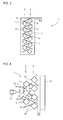
- FIG. 1 shows an inventive arrangement 1, which serves to protect an object such as primarily a motor vehicle, in particular an armored tracked vehicle.
- the arrangement consists of several, in cross-section prism-shaped profile bars, which in two separate rows 2, 3 (see Fig. 2 ) are arranged.
- the profile bars 4 of the first row 2 are superposed and parallel to each other, but spaced from each other.
- the profile bars 5 of the second row 3 are one above the other and parallel to each other extending, but also spaced from each other.
- the two rows 2, 3 are positioned offset in such a way that the profiled bars 4, as seen from the front 6 of the arrangement 1, cover the gaps between two profiled bars 5 of the second row 3 lying behind them. So it looks like, seen from the side, a quasi-closed front.
- the profile bars 4 are shown in cross section square, square in the illustrated example. But they can also be diamond-shaped, or have a cross-sectional shape with even more edges.
- the cross-sectional areas of the profiled bars 4 and 5 may be the same, but they may also differ, in which case preferably the cross-sectional areas of the profiled bars 4 of the first row 2 are smaller than the cross-sectional areas of the profiled bars 5 of the second row 3.
- the distances, seen vertically, between two profile bars 4 and two profile bars 5 may be between 3 to 100 mm, ultimately the concrete selected geometric arrangement of the cross-sectional shape and the cross-sectional area of the individual profile bars depends, since it must be ensured that the profile bars cover the gaps between two profile bars 5.
- the profiled bars 4 and 5 are made of metallic material, they can be solid profiles or hollow profiles, optionally filled (eg with sand or the like). They are preferably made of simple structural steel, so not expensive steel armor. This is because they have a high protective effect, which is not based on outstanding strength properties of the material used, but on a purposeful creation of contours, which serve the fragmentation of an impacting projectile, which then breaks down into a plurality of individual sub-projectiles, which is defined in move created free spaces between the profiled bars 4, 5 and hit there on defined surfaces, so that it comes to a total of a high degree of fragmentation of the impinging projectile, associated with high momentum transfers to the participating profile bars under destruction of kinetic energy of the sub-projectiles such that these sub-projectiles, if at all, only with low penetration power on the underlying armor of the motor vehicle meet and there can do no harm.
- a holder 7 can be seen, in the embodiment shown, see FIG. 1 , two such holders 7 are provided. These have corresponding openings 8, 9, which essentially the Geometry of the profile bars correspond, so that they can be inserted through the opening 8, 9.
- the inserted profile bars 4, 5 can then be welded in their final position on the brackets 7, so that a total of a prefabricated arrangement 1 results, which can be completely installed as such.
- Such an arrangement 1 has for example a length of 1 to 1.5 m, so that it can still be worn. Also allows such a dimension, by juxtaposed attachment of several such arrangement to cover a larger area, for example, a complete side surface of a tank. If the armored front to be protected, it is readily possible, for example, only two such arrangements 1 to install front.
- FIG. 3 shows an inventive arrangement 1, which in the construction of the Figures 1 and 2 equivalent. Also there are two rows 2, 3 consisting of profiled bars 4, 5 are formed, which in turn are received in at least two corresponding holders 7. Again, the inventive row offset is realized.
- Beulbleche 11 are also set here between the corresponding rows, which are optionally used on the two brackets 7 in corresponding receiving slots respectively fixed.
- These Beulblechen 11 may be simple metal sheets, but are also conceivable sandwich structures consisting of a metal layer and an applied plastic or rubber layer or the like.
- These Beulbleche work against additional hollow charge threats.
- Such shaped charges form highly dynamic high-load spikes, which can be greatly disturbed by the integrated Beulbleche.
- these Beulbleche also have against an attack with EFP projectiles, for example, an additional protective function, since they also inevitably act impulsive or energy-dissipating.
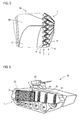
- FIG. 4 shows in the form of a schematic diagram of the operation of the inventive arrangement 1, which is shown here only in principle. Shown is the arrangement 1, which is positioned in front of a base armor 12 of a motor vehicle.
- the distance d between the back plane of the assembly 1 and the base armor 12 should be between 20 mm to 2000 mm, with an appropriate distance determined to be (in mm) at least 10 times the numerical value of the minimum cross-sectional area of a profile bar corresponds, provided that all profile bars 4, 5 have the same cross-sectional area, or the cross-sectional area average value. For example, if a profile bar has a cross-sectional area of 36 cm 2 , the distance d should be 360 mm.
- the profile bars 4, 5 are arranged so that in each case an edge 13, 14 in the direction of the approaching threat, here represented by an approaching projectile 15, is directed.
- the square profile bars 4, 5 are thus aligned so that the two diagonals are horizontal and vertical. That is, the respective bar surfaces 16 and 17 are at an angle not equal to 90 ° to horizontal, they are (assuming vertical alignment of the assembly 1) in the example shown at an angle of 45 ° to the horizontal.
- the projectile 15 for example an EFP projectile, encounters the arrangement 1. It strikes a profiled bar 4 of the first row 2 and meets there in the example shown on the projecting edge 13. This leads to a high degree of fragmentation and formation of many individual sub-projectiles 18, resulting from the inclined surfaces 16 after Be distracted at the top and bottom to the side. They move into the defined free spaces formed between the individual profile bars 4, 5 and meet there either on the quasi-inner surfaces 16 of the section bars 4 of the first row 2 or on edges or surfaces 17 of the section bars 5 of the second row 3.
- Beulbleche 11 While in the upper part of FIG. 4 no Beulbleche 11 are shown in the lower part of FIG. 4 exemplarily two Beulbleche 11 shown. These serve as further impact or deflection surfaces for the subprojectiles 18. That is, that to these Beulblechen 11, which are deformed upon impact of the subprojectiles 18, the subprojectiles 18 are braked, even there energy is destroyed.
- FIG. 4 shows the impact of an EFD projectile that can be effectively destroyed and thus reduced in its naturaldringungswin
- the inventive arrangement is also effective against shaped charges or against KE arrow ammunition.
- shaped charges in particular the integration of Beulbleche is appropriate.
- the protective function is also in terms of KE arrow ammunition, again, the effect against these thin, long projectiles based on an asymmetric cross-sectional load. Because the approaching long projectile experiences high shear and bending forces on impact, which break the projectile, so that it also comes here to a fragmentation.
- FIG. 5 shows a schematic diagram of an embodiment of a motor vehicle 19 according to the invention, which is only partially shown here. Shown is the lateral base armor 20 (corresponding to the basic armor 12 off FIG. 4 ) with chainwork 21 located in front of it.
- the arrangement 1 according to the invention shown is placed in front of the basic armor and pulled over the chain mechanism 21.
- the arrangement 1 is as in FIG. 3 shown executed, that is consisting of two rows 2, 3 of profiled bars 4, 5, which are arranged in vertical rows parallel to each other superimposed in the respective rows 2, 3, wherein the rows 2, 3 are positioned offset. Also provided here are the Beulbleche 11, which extend between the section bars 4 respectively 5, extending into the region of the respective other row, are arranged.
- arrangement 1 may be a prefabricated arrangement in the sense of FIGS. 1 to 3 act, in which therefore the profiled bars 4, 5 and possibly the Beulbleche 11 are firmly connected to the brackets 7, so that the entire assembly 1 can be attached as a one-piece component to the vehicle.
- the profiled bars 4, 5 and possibly the Beulbleche 11 are firmly connected to the brackets 7, so that the entire assembly 1 can be attached as a one-piece component to the vehicle.
- three or four such arrangements 1 are positioned side by side. If the vehicle height changes, that is, if the vehicle height decreases toward the front, it is conceivable to design such a prefabricated arrangement correspondingly also for this geometry.
- FIG. 6 shows a motor vehicle 19 according to the invention, in which on a vehicle side already an inventive arrangement 1, which extends over a part of the vehicle side, is shown. In the front side area, no arrangement is shown, but only a plurality of the vehicle either releasably mounted or fixed brackets 22 are shown, whose function ultimately corresponds to the brackets 7, with the difference that on them the profile bars 4, 5 and optionally the Beulbleche 11 not firmly and permanently mounted.
- the brackets 22 also have corresponding openings 23, 24, which serve to receive the profile bars 4, 5 and which are of course formed according to the geometric arrangement or orientation of the profile bars 4, 5 in a row and with the inventive row offset.
- the profiled bars 4, 5 are then inserted into these, if required, and fixed by means of suitable holding means (eg pins, locking pins, clamps, etc.), as is the case with the already installed arrangement 1.
- suitable holding means eg pins, locking pins, clamps, etc.
- brackets 22 are shown only on the side of the vehicle 19, it is of course conceivable to provide corresponding brackets in the area of the vehicle front and the rear of the vehicle, so that there is the possibility, there also corresponding profile bars 4, 5 to install.
- the illustrated brackets 22 are merely exemplary in nature. Of course, the specific geometry or design of such a holder may also be different. It only has to be able to securely hold the corresponding profile bars 4, 5 and possibly the bump plates 11 in the spatial arrangement provided according to the invention, so that the corresponding profile bar rows can be formed with the row offset according to the invention. Also, in principle, the attachment of an arrangement or positioning vehicle-side brackets is not limited to the two sides and the front-rear section. Rather, an arrangement on corresponding top or roof surfaces is conceivable to provide effective protection against approaching projectiles from above.
Abstract
Anordnung zum Schutz eines Objekts, insbesondere eines Kraftfahrzeugs, gegen anfliegende Projektile, bestehend aus mehreren im Querschnitt prismenförmigen Profilstäben (4, 5), die in wenigstens zwei hintereinander liegenden und voneinander beabstandeten Reihen (2, 3), in denen die jeweiligen parallel zueinander verlaufenden Profilstäbe (4, 5) voneinander beabstandet sind, angeordnet sind, wobei die Profilstäbe (4) der vorderen Reihe (2) die Lücken zwischen den Profilstäben (5) der hinteren Reihe (3) überdecken.Arrangement for protecting an object, in particular a motor vehicle, against approaching projectiles, comprising a plurality of profile bars (4, 5) prismatic in cross-section, arranged in at least two consecutive and spaced apart rows (2, 3) in which the respective mutually parallel Profile bars (4, 5) are spaced from each other, are arranged, wherein the profile bars (4) of the front row (2) cover the gaps between the profile bars (5) of the rear row (3).
Description
Die Erfindung betrifft eine Anordnung zum Schutz eines Objekts, insbesondere eines Kraftfahrzeugs wie eines gepanzerten Rad- oder Kettenfahrzeugs, gegen anfliegende Projektile.The invention relates to an arrangement for protecting an object, in particular a motor vehicle such as an armored wheeled or tracked vehicle, against approaching projectiles.
Insbesondere militärische Fahrzeuge, beispielsweise Kampf-, Schützen- und Transportpanzer, benötigen heutzutage einen möglichst polyvalenten und flexiblen Schutz gegen anfliegende Projektile. Ziel ist es, unter Verwendung einer entsprechenden additiven Anordnung das Kraftfahrzeug gegen unterschiedliche Bedrohungsszenarien zu schützen. Einerseits ist die Bedrohung in der asymmetrischen Kriegsführung von allen Seiten möglich, womit ein möglichst guter Rundumschutz nötig ist, andererseits sollten die Fahrzeuge auch in klassischen Bedrohungsszenarien möglichst gut geschützt sein, wobei die Duellfähigkeit und damit ein starker Schutz im Bereich der Kraftfahrzeugfront wichtig ist. Zweckmäßig ist eine Schutzanordnung, die, wenn möglich, beides realisiert.In particular, military vehicles, such as combat, rifle and transport tanks, today require the most polyvalent and flexible protection against approaching projectiles. The aim is to protect the vehicle against different threat scenarios using a corresponding additive arrangement. On the one hand, the threat in asymmetric warfare is possible from all sides, which requires the best possible all-round protection, on the other hand, the vehicles should be protected as well as possible in classic threat scenarios, the Duellfähigkeit and thus a strong protection in the field of motor vehicle front is important. It is expedient to have a protective arrangement which, if possible, realizes both.
Ein weiteres Problem besteht darin, dass sich die anfliegenden Projektile deutlich unterschiedlich sein können. So bilden Hohlladungen ein dünnes, sehr schnelles Projektil aus, während IED-EFPs (= improvised explosive device (IED), explosively formed projective (EFP)), große, schwere Projektile bilden, während KE-Munition (kinetische Energie (KE)) sehr dünne, lange und harte Projektile darstellen.Another problem is that the approaching projectiles can be significantly different. For example, shaped charges form a thin, very fast projectile, while IED EFPs (explosively formed projective (EFP)) form large, heavy projectiles, while KE ammunition (kinetic energy (KE)) is very represent thin, long and hard projectiles.
Besonderer Wert wird auf den seitlichen Schutz des Kraftfahrzeugs gelegt, da hier große Flächen geschützt werden müssen, zumal gerade im Falle einer asymmetrischen Kriegsführung viele verschiedene Bedrohungen aus seitlicher Richtung vorhanden sind.Special emphasis is placed on the lateral protection of the motor vehicle, since here large areas must be protected, especially as in the case of asymmetric warfare many different threats from the side are available.
Im Rahmen der unterschiedlichen Projektile sind insbesondere die IED-EFPs besonders problematisch, sie stellen die größten Anforderungen an die Panzerung derartiger Kraftfahrzeuge. Es handelt sich dabei um Sprengladungen, welche die Detonationsenergie von Sprengstoffen nutzen, um ein oder mehrere Geschosse aus einem duktilen Material zu verformen, die auf Geschwindigkeiten von 1500 bis 3000 m/s zielgerichtet beschleunigt werden. Hierbei sind Durchdringungsleistungen von über 100 mm in Panzerstahl durchaus üblich. Splitterladungen sowie sogar fokussierte Splitterladungen sind heute ebenfalls weit verbreitete Bedrohungen, diese erreichen jedoch nicht die Durchdringungsleistung der beschriebenen EFPs. Wird folglich ein wirkungsvoller Schutz gegen die IED-EFPs erreicht, ist folglich auch gleichzeitig ein sehr wirkungsvoller Schutz gegen andere Bedrohungen gegeben.Among the different projectiles, the IED EFPs are particularly problematic, they make the greatest demands on the armor of such vehicles. These are explosive charges that use the detonation energy of explosives to deform one or more projectiles of a ductile material, which are purposefully accelerated to speeds of 1500 to 3000 m / s. Penetration powers of over 100 mm in armored steel are quite common here. Fragmentation charges and even focused fragmentation charges are also common threats today, but these do not achieve the penetration performance of the described EFPs. As a result, effective protection against the IED EFPs also provides very effective protection against other threats.
Aus
Der Erfindung liegt damit das Problem zugrunde, eine an ein Kraftfahrzeug adaptierbare Schutzanordnung anzugeben, die im Aufbau einfach ist, gleichzeitig aber den entsprechenden Flächenschutz bietet.The invention is therefore based on the problem of specifying an adaptable to a motor vehicle protection arrangement that is simple in construction, but at the same time provides the appropriate surface protection.
Zur Lösung dieses Problems ist erfindungsgemäß eine Anordnung zum Schutz eines Objekts, insbesondere eines Kraftfahrzeugs gegen anfliegende Projektile vorgesehen, bestehend aus mehreren im Querschnitt prismenförmigen Profilstäben, die in wenigstens zwei hintereinanderliegenden und voneinander beabstandeten Reihen, in denen die jeweiligen parallel zueinander verlaufenden Profilstäbe voneinander beabstandet sind, angeordnet sind, wobei die Profilstäbe der vorderen Reihe die Lücken zwischen den Profilstäben der hinteren Reihe überdecken.To solve this problem, the invention provides an arrangement for protecting an object, in particular a motor vehicle against approaching projectiles, consisting of several prismatic in cross-section profile bars, in at least two rows one behind the other and spaced apart, in where the respective mutually parallel profile bars are spaced from each other, are arranged, wherein the profile bars of the front row cover the gaps between the section bars of the rear row.
Die erfindungsgemäße Anordnung, die adaptiv an einem Kraftfahrzeug wie einem Panzer oder dergleichen angeordnet werden kann, besteht aus zwei gestaffelt hintereinander angeordneten Reihen jeweils bestehend aus mehreren parallel zueinander verlaufenden Profilsstäben, die ebenfalls voneinander beabstandet sind. Die beiden Reihen sind so angeordnet, dass sie versetzt liegen, das heißt, dass die Profilstäbe der vorderen ersten Reihe die Lücken der zwischen den Profilstäben der hinteren zweiten Reihe überdecken. Es ergibt sich also, gesehen von der Seite, eine geschlossene Fläche, die jedoch geometrisch unterteilt respektive strukturiert ist. Die Profilstäbe selbst weisen einen prismenförmigen Querschnitt auf. Bevorzugt sind sie viereckig, beispielsweise rautenförmig oder quadratisch, wobei aber auch fünf- oder sechseckige Querschnittsformen denkbar sind.The inventive arrangement, which can be arranged adaptively on a motor vehicle such as a tank or the like, consists of two staggered successively arranged rows each consisting of a plurality of mutually parallel profiled bars, which are also spaced from each other. The two rows are arranged so that they are offset, that is, the profile bars of the front first row cover the gaps between the profile bars of the rear second row. Thus, as seen from the side, it results in a closed surface, which, however, is divided or structured geometrically. The profile bars themselves have a prismatic cross-section. Preferably, they are quadrangular, for example diamond-shaped or square, but also five- or hexagonal cross-sectional shapes are conceivable.
Die erfindungsgemäße Anordnung lässt eine gezielte Störung respektive Zerstörung der anfliegenden Projektile, insbesondere der EFPs zu. Durch die versetzte Anordnung der Profilstabreihen entstehen definierte Freiräume, in die die sich zerlegenden Projektilmassen durch wechselwirkende und aus verschiedenen Richtungen wirkende Impulskräfte bewegen können. Die Wirkungsweise beruht hier folglich nicht auf der Festigkeit des Materials, sondern auf Massenträgheit und den Impulsgesetzen in der Interaktion von Projektil und Profilstab. Denn infolge der beschriebenen Positionierung der Reihen respektive der Profilstäbe und der Schaffung der definierten Freiräume kommt es dazu, dass sich die Projektile aufprall- respektive impulsbedingt selbst zerlegen. Je schneller und damit gefährlicher die Projektile sind, umso besser ist die Störwirkung. Neben Schutz gegen EFPs ist auch ein Schutz gegen Splitterladung gegeben, da Splitterladungen deutlich geringere Durchdringungsleistungen besitzen als EFPs, wie auch Schutz gegen Pfeilgeschosse gegeben ist. Diese werden durch asymmetrische Querschnittsbelastungen zerbrochen und in einzelne Bruchstücke aufgetrennt, die sich wiederum in die Freiräume bewegen können. Wie beschrieben sind die Profilstäbe im Querschnitt bevorzugt viereckig, sie können eine quadratische Form oder Rautenform besitzen. Die Kanten können eckig oder leicht abgerundet sein.The arrangement according to the invention allows a targeted disruption or destruction of the approaching projectiles, in particular the EFPs. The staggered arrangement of the profile rod rows creates defined free spaces into which the dispersing projectile masses can move by means of interacting momentum forces acting from different directions. The mode of action is therefore not based on the strength of the material, but on inertia and the momentum laws in the interaction of projectile and profile bar. Because of the described positioning of the rows respectively the profile bars and the creation of the defined clearances, it happens that the projectiles collide impulsively or impulsively themselves. The faster and more dangerous the projectiles are, the better the interference effect. In addition to protection against EFPs, there is also protection against fragmentation, since fragment charges have significantly lower penetration powers than EFPs, as is protection against shotguns. These are broken by asymmetric cross-sectional stresses and separated into individual fragments, which in turn can move into the open spaces. As described, the profile bars in cross section are preferably quadrangular, they may have a square shape or diamond shape. The edges can be angular or slightly rounded.
Die Anordnung ist dabei derart, dass vorzugsweise zumindest die Profilstäbe der ersten, vom Fahrzeug abgewandten Reihe derart angeordnet sind, dass die Kanten seitlich vorstehen. Auch die Profilstäbe der zweiten Reihe können so angeordnet sein, dass eine Kante seitlich vorsteht, das heißt, dass die Ausrichtung der Profilstäbe beider Reihen gleich ist. Die Profilstabflächen stehen folglich schräg, so dass ein auftreffendes Projektil letztlich zur Seite hin abgelenkt ist und in einen definierten Freiraum eintritt.The arrangement is such that preferably at least the profile bars of the first row facing away from the vehicle are arranged such that the edges protrude laterally. The profile bars of the second row can also be arranged that one edge protrudes laterally, that is, the orientation of the profile bars of both rows is the same. The profile bar surfaces are therefore inclined so that an impacting projectile is ultimately deflected to the side and enters a defined space.
Die Profilstäbe der ersten und zweiten Reihe können vorzugsweise einen Querschnitt von 2 bis 200 cm2 aufweisen. Dabei können die Profilstäbe der beiden Reihen die gleiche Querschnittsfläche aufweisen, zweckmäßig bevorzugt jedoch weisen die Profilstäbe der ersten Reihe eine kleinere Querschnittsfläche A1 als die (A2) der zweiten Reihe auf. Es ist aber auch möglich, dass die Profilstäbe der zweiten Reihe eine kleinere Querschnittsfläche als die der ersten Reihe aufweisen. Verallgemeinernd kann man sagen, dass die Größe der Querschnittsflächen in den beiden Reihen voneinander abweichen kann, beispielsweise um ca. 10 %. Die Querschnittfläche kann um einen Faktor > 0,5 und < 1,0, insbesondere zwischen 0,7 bis 0,9 kleiner sein, also z. B. A1 = 0,9 A2.The profile bars of the first and second rows may preferably have a cross section of 2 to 200 cm 2 . In this case, the profile bars of the two rows may have the same cross-sectional area, but advantageously the profile bars of the first row have a smaller cross-sectional area A 1 than the (A 2 ) of the second row. But it is also possible that the profile bars of the second row have a smaller cross-sectional area than that of the first row. In general, one can say that the size of the cross-sectional areas in the two rows may differ, for example by about 10%. The cross-sectional area may be smaller by a factor of> 0.5 and <1.0, in particular between 0.7 to 0.9, so z. B. A 1 = 0.9 A 2 .
Der Abstand eines Profilsstabs der ersten Reihe von einem benachbarten Profilstab der zweiten Reihe sollte zwischen 3 bis 100 mm betragen. Der konkret zu wählende Abstand hängt natürlich von der jeweiligen Querschnittsfläche der Profilstäbe der einzelnen Reihen ab, wie auch deren Abstand innerhalb der einzelnen Reihen. Der Abstand sollte so sein, dass sich hinreichend große Freiräume ergeben, in die die abgelenkten, sich zerlegenden Projektilteile nach dem ersten Aufprall auf die erfindungsgemäße Anordnung, im Rahmen dessen sie durch Zerlegung des anfliegenden Projektils aufgefächert wurden, verbunden mit dem entsprechenden Energieabbau, eindringen können.The distance of a profile bar of the first row from an adjacent profile bar of the second row should be between 3 to 100 mm. Of course, the distance to be chosen depends on the particular cross-sectional area of the profile bars of the individual rows, as well as their spacing within the individual rows. The distance should be such that sufficiently large free spaces result, into which the deflected projectile parts which break down after the first impact can penetrate the arrangement according to the invention, in the course of which they have been fanned out by breaking up the approaching projectile, connected with the corresponding energy reduction ,
Die Profilstäbe sind zweckmäßigerweise aus metallischem Material. Da die erfindungsgemäße Wirkungsweise nicht auf der Festigkeit des Materials, sondern auf Massenträgheit und den Impulsgesetzen im Rahmen der Interaktion von Projektil und Profilstäben beruht, kann bei der erfindungsgemäßen Anordnung ein kostengünstiges Material wie beispielsweise Baustahl anstelle von Panzerstahl verwendet werden.The profile bars are suitably made of metallic material. Since the effect of the invention is not based on the strength of the material, but on inertia and the pulse laws in the interaction of projectile and profile bars, in the inventive arrangement, a cost-effective material such as structural steel instead of armored steel can be used.
Die Profilstäbe selbst können als Vollprofile oder als Hohlprofile ausgeführt sein, wobei grundsätzlich die Möglichkeit besteht, ein etwaiges Hohlprofil auch mit einem zusätzlichen Material zu füllen, wenn dies aus Gründen der Energiedissipation zweckmäßig ist.The profile bars themselves can be designed as solid profiles or as hollow profiles, wherein in principle it is possible to fill a possible hollow profile with an additional material, if this is expedient for reasons of energy dissipation.
Eine zweckmäßige Weiterbildung der Erfindung sieht vor, dass zwischen den Profilstäben einer Reihe, sich vorzugsweise zwischen die Profilstäbe der anderen Reihe fortsetzend, schräg verlaufende Beulbleche angeordnet sind. Diese integrierten Beulbleche wirken zusätzlich gegen Hohlladungsbedrohungen. Solche Hohlladungen erzeugen hochdynamische Hochladungsstachel, welche durch die integrierten Beulbleche, die als zusätzliche Prall- und Ablenkflächen dienen, stark gestört werden und dadurch eine nur geringe Resteindringungsfähigkeit in die Grundpanzerung des geschützten Fahrzeugs besitzen.An expedient development of the invention provides that between the profile bars of a series, preferably continuing between the profile bars of the other row, inclined Beulbleche are arranged. These integrated Beulbleche additionally act against hollow charge threats. Such shaped charges generate highly dynamic high-load spikes, which are strongly disturbed by the integrated Beulbleche, which serve as additional baffle and deflection surfaces, and thus have a low Resistance to penetration into the base armor of the protected vehicle.
Diese Beulbleche können als einlagige Bleche oder als Sandwichbauteile, insbesondere bestehend aus einer Gummi- oder Kunststofflage und wenigstens einer Lage aus metallischem Material ausgeführt sein. Der Sandwichaufbau und die daraus resultierende Verformbarkeit ist hinsichtlich des Abbaus kinetischer Energie ebenfalls zweckmäßig.This Beulbleche can be designed as single-layer sheets or as sandwich components, in particular consisting of a rubber or plastic layer and at least one layer of metallic material. The sandwich construction and the resulting deformability is also expedient with regard to the degradation of kinetic energy.
Erfindungsgemäß sind die Metallprofile, und gegebenenfalls auch die Beulbleche, an mehreren gemeinsamen Halterungen, die sie gegebenenfalls durchsetzen, angeordnet. Die Profilstäbe weisen eine Länge von einem oder mehreren Metern auf, so dass sich die gesamte gatterartige Anordnung über eine entsprechende Fahrzeuglänge erstreckt. Je nachdem, wie hoch der zu schützende Fahrzeugbereich ist, wird die Anzahl der reihenmäßig verwendeten Profilstäbe gewählt. Um die Profilstäbe auf einfache Weise in ihrer Relativposition zueinander zu fixieren, sind entsprechende Halterungen vorgesehen, beispielsweise entsprechende Bleche oder ähnliche Träger, an denen die Profilstäbe der einzelnen Reihen angeordnet sind. Kommen beispielsweise Haltebleche zum Einsatz, so können diese mit entsprechenden Ausnehmungen, die der Querschnittsform der Profilstäbe entsprechen, versehen sein, durch welche die Profilstäbe geführt werden.According to the invention, the metal profiles, and optionally also the bump plates, are arranged on a plurality of common mounts which they possibly pass through. The profile bars have a length of one or more meters, so that the entire gate-like arrangement extends over a corresponding vehicle length. Depending on how high the vehicle area to be protected is, the number of profile bars used in rows is selected. To fix the profile bars in a simple manner in their relative position to each other, corresponding brackets are provided, for example, corresponding sheets or similar support on which the profile bars of the individual rows are arranged. If, for example, holding plates are used, then they can be provided with corresponding recesses which correspond to the cross-sectional shape of the profile bars, through which the profile bars are guided.
Dabei können die Halterungen von Haus aus fahrzeugseitig vorgesehen sein, das heißt, dass die Anordnung quasi fahrzeugseitig aufgebaut wird. Denkbar ist es aber auch, die Anordnung quasi als vorgefertigtes Gatter auszuführen und die Profilstäbe und gegebenenfalls auch die Beulbleche an entsprechenden separaten Halterungen anzuordnen, wobei diese Halterungen dann gleichzeitig als Befestigungselemente zur Anbringung der gesamten Anordnung am zu schützenden Kraftfahrzeug dienen können. Ist eine Anordnung nicht allzu lang, kann sie durchaus auch von zwei Mann gehoben werden und versetzt werden. Das heißt, dass beispielsweise eine Fahrzeugseite durch Nebeneinandersetzen von drei oder vier Anordnungen geschützt werden kann. Soll die Fahrzeugfront geschützt werden, ist es ohne weiteres möglich, zwei Anordnungen an der Fahrzeugfront zu positionieren, wobei dort wiederum die Fixierung über die entsprechenden Halterungen möglich ist.The brackets can be provided on the vehicle side of the house, that is, the arrangement is virtually built on the vehicle side. It is also conceivable, however, to carry out the arrangement quasi as a prefabricated gate and to arrange the profiled bars and optionally also the Beulbleche on corresponding separate brackets, which brackets can then serve as fasteners for attaching the entire arrangement on the motor vehicle to be protected at the same time. If an arrangement is not too long, it can certainly be lifted by two men and transferred. That is, for example, a vehicle side protected by side-by-side of three or four arrangements can be. If the vehicle front is to be protected, it is readily possible to position two arrangements on the front of the vehicle, in which case the fixation via the corresponding holders is again possible.
Sind die Profilstäbe in fahrzeugseitig fest vorgesehenen Halterungen eingesetzt, so ist ein Umrüsten selbstverständlich ebenfalls sehr einfach möglich. Dies setzt jedoch voraus, dass bei einem Versetzen der Anordnung von der Seite zur Fahrzeugfront natürlich auch frontseitig entsprechende Halterungen vorgesehen sind.If the profile bars are used in vehicle-mounted brackets firmly, of course, a conversion is also very easily possible. However, this presupposes that, of course, if the arrangement is offset from the side to the front of the vehicle, corresponding brackets are also provided on the front side.
Neben der Anordnung selbst betrifft die Erfindung ferner ein Kraftfahrzeug, z. B. ein Kettenfahrzeug oder ein anderes gepanzertes Fahrzeug, umfassend eine oder mehrere an einer Seite oder der Front oder dem Heck angebrachte Anordnungen der zuvor beschriebenen Art. Dabei können die entsprechenden Halterungen, die die Profilstäbe und gegebenenfalls die Beulbleche tragen, bereits fahrzeugseitig fest vorgesehen sein, so dass zum Aufbau der Anordnung lediglich die einzelnen Profilstäbe und gegebenenfalls Beulbleche positioniert werden. Denkbar ist es aber auch, vorgefertigte Anordnungen als komplette Schutzelemente fahrzeugseitig zu positionieren, wobei dann jede Anordnung über entsprechende Halterungen respektive Befestigungselemente verfügt, um sie am Fahrzeug zu fixieren.In addition to the arrangement itself, the invention further relates to a motor vehicle, for. As a tracked vehicle or other armored vehicle, comprising one or more attached to one side or the front or the rear arrangements of the type described above. In this case, the corresponding brackets that carry the profile bars and possibly the Beulbleche already be provided on the vehicle side fixed , so that only the individual profile bars and optionally Beulbleche be positioned to build the arrangement. It is also conceivable, however, to position prefabricated arrangements as complete protective elements on the vehicle side, in which case each arrangement has corresponding holders respectively fastening elements in order to fix them to the vehicle.
Zweckmäßigerweise ist die jeweilige Anordnung zu einer am Kraftfahrzeug vorgesehenen Panzerung beabstandet angeordnet. Auch über diesen Abstand wird ein gewisser, für die Effektivität notwendiger Freiraum realisiert, der zwar einen Volumenaufwuchs des Schutzes gegenüber der zu schützenden Kraftfahrzeugstruktur bedingt. Dieser Freiraum muss jedoch kein Totvolumen sein, sondern kann zum Beispiel als Stauraum genutzt werden. Das Anfüllen dieses Freiraums mit verstauenden Utensilien, die als weitere "Absorptionselemente" dienen können, kann den Schutzgrad durchaus noch verbessern.The respective arrangement is expediently arranged at a distance from an armor provided on the motor vehicle. Also over this distance, a certain, necessary for the effectiveness clearance is realized, although a volume growth of the protection against the protected motor vehicle structure due. However, this free space does not have to be a dead volume, but can be used for example as storage space. The filling of this space with stowing utensils, which can serve as further "absorption elements", can certainly improve the degree of protection.
Der Abstand der zweiten Reihe der Anordnung zum Kraftfahrzeug respektive der Grundpanzerung des Fahrzeugs sollte zwischen 20 bis 2000 mm betragen. Das heißt, dass die Anordnung entweder sehr nah an der Grundpanzerung des Kraftfahrzeugs angeordnet werden kann, sie kann aber auch in deutlichem Abstand dazu angeordnet werden, wozu dann natürlich entsprechende Abstandshalter oder dergleichen bei Bedarf zu verwenden sind. Der Abstand sollte wenn möglich so bemessen sein, dass er ungefähr dem zehnfachen des Wertes der kleinsten oder durchschnittlichsten Querschnittsfläche der verwendeten Profilstäbe entspricht. Kommen also Profilstäbe mit beispielsweise 25 cm2 zum Einsatz, so sollte der Abstand der Anordnung zur Grundpanzerung 250 mm betragen.The distance between the second row of the arrangement to the motor vehicle or the base armor of the vehicle should be between 20 to 2000 mm. This means that the arrangement can be arranged either very close to the base armor of the motor vehicle, but it can also be arranged at a considerable distance to what then, of course, corresponding spacers or the like are to be used if necessary. If possible, the distance should be such that it corresponds approximately to ten times the value of the smallest or the average cross-sectional area of the profiled bars used. So come profile bars For example, with 25 cm 2 used, so the distance of the arrangement to the basic armor should be 250 mm.
Wie bereits zur zuvor beschriebenen Anordnung ausgeführt, besteht die Möglichkeit, jede Anordnung quasi als separates, vorgefertigtes gatterartiges Bauteil auszuführen. An der oder jeder Anordnung sind dann entsprechende Befestigungselemente vorgesehen, mittels denen die Anordnung fahrzeugseitig lösbar befestigbar ist. Sind anordnungsseitig entsprechende Halterungen in Form von Halteblechen oder ähnlichem, an denen die Profilstäbe und gegebenenfalls die Beulbleche angeordnet sind, vorgesehen, so können diese Halterungen gleichzeitig als entsprechende Befestigungselemente ausgeführt sein, beispielsweise indem entsprechende Einhängehaken, mit denen die Halterungen und damit die Anordnungen an entsprechenden Abschnitten an der Fahrzeugfläche eingehängt werden können, oder entsprechend Durchbrechungen zur Ermöglichung einer Verschraubung und ähnliches vorgesehen sind.As already stated for the previously described arrangement, it is possible to design each arrangement virtually as a separate, prefabricated gate-like component. At the or each arrangement corresponding fasteners are then provided, by means of which the arrangement on the vehicle side releasably fastened. Are the arrangement side corresponding brackets in the form of holding plates or the like, where the profile bars and optionally the Beulbleche are arranged, provided, these brackets can also be designed as corresponding fasteners, for example, by appropriate hooks with which the brackets and thus the arrangements to appropriate Sections can be hung on the vehicle surface, or according to openings for enabling a screw connection and the like are provided.
Alternativ ist es aber auch denkbar, am Fahrzeug selbst entsprechende Halterungen vorzusehen, in denen die Profilstäbe und gegebenenfalls die Beulbleche der Anordnung lösbar befestigt sind. Das heißt, dass im Bereich der Flächen, vor welchen die Anordnung zu positionieren ist, entsprechende Halterungen vorgesehen sind, beispielsweise Halterungen, in die die einzelnen Profilstäbe eingelegt und fixiert werden, oder in die sie von der Seite her eingeschoben werden etc. Die Halterungen müssen natürlich grundsätzlich so konzipiert sein, dass beim Fahren die Profilstäbe sich nicht selbstständig lösen, sondern sicher fixiert sind.Alternatively, it is also conceivable to provide the vehicle itself corresponding brackets in which the profile bars and optionally the Beulbleche the arrangement are releasably secured. This means that in the area of the surfaces in front of which the arrangement is to be positioned, corresponding holders are provided, for example holders in which the individual profile bars are inserted and fixed, or in which they are inserted from the side, etc. The holders must Of course, basically be designed so that when driving the profile bars do not solve independently, but are securely fixed.
Um in dem Fall, dass fahrzeugseitig die Halterungen vorgesehen sind, eine Umrüstung der Gestalt zu ermöglichen, dass die Anordnung beispielsweise von der Fahrzeugseite zur Fahrzeugfront umgebaut wird, sind über die Fahrzeugfläche an unterschiedlichen Positionen entsprechende Halterungen vorgesehen, so dass es ohne weiteres möglich ist, die Profilstäbe und gegebenenfalls die Beulbleche den Halterungen an der Fahrzeugseite zu entnehmen und beispielsweise in die frontseitigen Halterungen einzusetzen. Im Falle der Verwendung vorgefertigter gatterartiger Anordnungen erfolgt die Umrüstung einfach dadurch, dass die entsprechenden Anordnungen komplett vom Fahrzeug abgenommen und an anderer Position am Fahrzeug wieder befestigt werden.In order, in the event that the brackets are provided on the vehicle side, to allow the configuration to be converted so that the arrangement is rebuilt, for example, from the vehicle side to the vehicle front, corresponding brackets are provided over the vehicle surface at different positions, so that it is readily possible to to take the profile bars and optionally the Beulbleche the brackets on the vehicle side and use, for example, in the front brackets. In the case of the use of prefabricated gate-like arrangements, the conversion is carried out simply by the fact that the corresponding arrangements are completely removed from the vehicle and attached to another position on the vehicle again.
Insbesondere im letztgenannten Fall ist es zweckmäßig, die Anordnungen entsprechend kurz auszuführen, beispielsweise mit einer Länge von 1, 1,5 oder 2 m. In diesem Fall sind dann zum Schützen einer Seite eines Fahrzeugs mehrere solcher Halterungen nebeneinander anzuordnen. Handelt es sich bei dem Fahrzeug beispielsweise um einen Panzer mit einer Länge von 6 m, so wären zum Schutz der Fahrzeugseite einschließlich des Kettenwerks beispielsweise vier Anordnungen zu verwenden, die nebeneinander positioniert werden. Soll eine Umrüstung erfolgen und soll die Panzerfront geschützt werden, so ist es ohne weiteres möglich, zwei kurze Anordnungen an der Seite zu entnehmen und frontseitig zu befestigen. Die dann gegebene gesamte Anordnungslänge von, obigem Beispiel folgend, 2, 3 oder 4 m deckt die Panzerfront entsprechend ab.In particular, in the latter case, it is expedient to carry out the arrangements according to short, for example, with a length of 1, 1.5 or 2 m. In this case, then to protect one side of a vehicle several such brackets are arranged side by side. For example, if the vehicle is a six meter long tank, for example, to protect the vehicle side, including the catenary, four assemblies would be used, positioned side by side. If a conversion is to be done and the armored front should be protected, it is easily possible to take two short arrangements on the side and secure the front. The given total arrangement length of 2, 3 or 4 m following the example above covers the tank front accordingly.
Weitere Vorteile, Merkmale und Einzelheiten der Erfindung ergeben sich aus dem in folgendem Ausführungsbeispiel sowie anhand der Zeichnungen. Dabei zeigen:
Figur 1- eine Vorderseitenansicht einer erfindungsgemäßen Anordnung,
Figur 2- eine Seitenansicht der Anordnung aus
Figur 1 , Figur 3- eine Seitenansicht einer Anordnung einer zweiten Ausführungsform,
Figur 4- eine Prinzipdarstellung der Funktionsweise einer erfindungsgemäßen Anordnung,
Figur 5- ein Beispiel der Montage einer erfindungsgemäßen Anordnung an einem Kettenfahrzeug, und
Figur 6- eine Prinzipdarstellung eines erfindungsgemäßen Kraftfahrzeugs mit einer erfindungsgemäßen Anordnung.
- FIG. 1
- a front view of an arrangement according to the invention,
- FIG. 2
- a side view of the arrangement
FIG. 1 . - FIG. 3
- a side view of an arrangement of a second embodiment,
- FIG. 4
- a schematic diagram of the operation of an inventive arrangement,
- FIG. 5
- an example of mounting an inventive arrangement on a tracked vehicle, and
- FIG. 6
- a schematic diagram of a motor vehicle according to the invention with an inventive arrangement.
Die Profilstäbe 4 sind ersichtlich im Querschnitt viereckig, im gezeigten Ausgangsbeispiel quadratisch. Sie können aber auch rautenförmig sein, oder eine Querschnittsform mit noch mehr Kanten besitzen. Die Querschnittsflächen der Profilstäbe 4 und 5 können gleich sein, sie können sich aber auch unterscheiden, wobei dann bevorzugt die Querschnittsflächen der Profilstäbe 4 der ersten Reihe 2 kleiner sind als die Querschnittsflächen der Profilstäbe 5 der zweiten Reihe 3.The profile bars 4 are shown in cross section square, square in the illustrated example. But they can also be diamond-shaped, or have a cross-sectional shape with even more edges. The cross-sectional areas of the profiled
Die Abstände, vertikal gesehen, zwischen zwei Profilstäben 4 respektive zwei Profilstäben 5 können zwischen 3 bis 100 mm betragen, wobei letztlich die konkret gewählte geometrische Anordnung von der Querschnittsform und der Querschnittsfläche der einzelnen Profilstäbe abhängt, da ja sichergestellt sein muss, dass die Profilstäbe 4 die Lücken zwischen zwei Profilstäben 5 überdecken.The distances, seen vertically, between two
Die Profilstäbe 4 und 5 sind aus metallischem Material, es kann sich um Vollprofile oder Hohlprofile, gegebenenfalls gefüllt (z. B. mit Sand oder ähnlichem) handeln. Sie sind bevorzugt aus einfachem Baustahl, also nicht aus teurem Panzerstahl. Dies deshalb, als sie eine hohe Schutzwirkung besitzen, die nicht auf herausragenden Festigkeitseigenschaften des verwendeten Materials beruht, sondern auf einer gezielten Schaffung von Konturen, die der Aufsplitterung eines auftreffenden Projektils dienen, das sich sodann in eine Vielzahl einzelner Teilprojektile zerlegt, die sich in definiert geschaffene Freiräume zwischen den Profilstäben 4, 5 bewegen und dort wieder an definierten Flächen aufschlagen, so dass es insgesamt zu einer hochgradigen Zersplitterung des auftreffenden Projektils kommt, verbunden mit hohen Impulsübertragungen auf die beteiligten Profilstäbe unter Vernichtung kinetischer Energie der Teilprojektile derart, dass diese Teilprojektile, wenn überhaupt, nur mit geringer Durchdringungsleistung auf die dahinterstehende Panzerung des Kraftfahrzeugs treffen und dort keinen Schaden anrichten können.The profiled bars 4 and 5 are made of metallic material, they can be solid profiles or hollow profiles, optionally filled (eg with sand or the like). They are preferably made of simple structural steel, so not expensive steel armor. This is because they have a high protective effect, which is not based on outstanding strength properties of the material used, but on a purposeful creation of contours, which serve the fragmentation of an impacting projectile, which then breaks down into a plurality of individual sub-projectiles, which is defined in move created free spaces between the profiled
In der Seitenansicht gemäß
Um eine einfache Anbringung zu ermöglichen sind im gezeigten Beispiel lediglich prinziphaft Befestigungselemente 10, hier Haken, an den Halterungen 7 dargestellt, mit denen die Anordnung 1 in entsprechende Einhängeabschnitte, die kraftfahrzeugseitig vorgesehen sind, eingehängt werden kann, wobei natürlich zusätzliche Mittel zur sicheren Befestigung noch verwendet werden können, um ein Verlieren einer Anordnung bei fahrendem Fahrzeug zu vermeiden.To allow easy attachment are in the example shown
Ersichtlich sind hier zusätzlich Beulbleche 11 zwischen die entsprechenden Reihen gesetzt, die gegebenenfalls an den beiden Halterungen 7 in entsprechenden Aufnahmeschlitzen eingesetzt respektive fixiert sind. Bei diesen Beulblechen 11 kann es sich um einfache Metallbleche handeln, denkbar sind aber auch Sandwichstrukturen bestehend einer Metalllage und einer aufgebrachten Kunststoff- oder Gummilage oder ähnlichem. Diese Beulbleche wirken gegen zusätzliche Hohlladungsbedrohungen. Solche Hohlladungen bilden hoch dynamische Hochladungsstachel, die durch die integrierten Beulbleche stark gestört werden können. Natürlich haben diese Beulbleche auch gegenüber einem Beschuss mit beispielsweise EFP-Projektilen eine zusätzliche Schutzfunktion, da sie zwangsläufig ebenfalls impuls- respektive energievernichtend wirken.Obviously Beulbleche 11 are also set here between the corresponding rows, which are optionally used on the two
Wie
Es sei angenommen, dass das Projektil 15, beispielsweise ein EFP-Projektil, auf die Anordnung 1 trifft. Es schlägt an einem Profilstab 4 der ersten Reihe 2 auf und trifft dort im gezeigten Beispiel auf die vorspringende Kante 13. Dies führt dazu, dass zu einer hochgradigen Zersplitterung und Bildung von vielen einzelnen Teilprojektilen 18 kommt, die resultierend aus den schräg verlaufenden Flächen 16 nach oben und unten zur Seite hin abgelenkt werden. Sie bewegen sich in die definiert ausgebildeten Freiräume zwischen den einzelnen Profilstäben 4, 5 und treffen dort entweder auf die quasi innenliegenden Flächen 16 der Profilstäbe 4 der ersten Reihe 2 oder auf Kanten oder Flächen 17 der Profilstäbe 5 der zweiten Reihe 3. Auch dort kommt es zwangsläufig zu Kollisionen und folglich zu einem Impulsabbau respektive einer Energievernichtung, so dass die Teilprojektile 18 einerseits aufgrund der Zersplitterung, andererseits aufgrund dieser Abbremsung und Energievernichtung eine extrem starke Reduzierung ihrer Durchdringungsfähigkeit erfahren. Die wenigen Teilprojektile 18, die bis auf die Grundpanzerung 12 durchdringen, sind derart abgebremst, dass sie dort keinen Schaden verrichten.It is assumed that the projectile 15, for example an EFP projectile, encounters the
Während im oberen Teil von
Während
Bei der in
Grundsätzlich denkbar ist es aber auch, die Anordnung 1 quasi erst am Kraftfahrzeug, also beispielsweise im Panzer, selbst aufzubauen. Ein solches Beispiel ist in
Die Halterungen 22 weisen ebenfalls entsprechende Durchbrechungen 23, 24 auf, die der Aufnahme der Profilstäbe 4, 5 dienen und die natürlich entsprechend der geometrischen Anordnung respektive Ausrichtung der Profilstäbe 4, 5 in Reihenform und mit dem erfindungsgemäßen Reihenversatz ausgebildet sind. In diese werden nun bei Bedarf die Profilstäbe 4, 5 eingeschoben und über geeignete Haltemittel (z. B. Zapfen, Steckbolzen, Klammern etc.) fixiert, wie dies bei der bereits verbauten Anordnung 1 erfolgt ist. Sind alle Profilstäbe 4, 5 und gegebenenfalls die Beulbleche 11 gesetzt, ist die Anordnung 1 aufgebaut, die Fahrzeugseite ist geschützt.The
Wenngleich hier entsprechende Halterungen 22 nur an der Seite des Fahrzeugs 19 dargestellt sind, ist es selbstverständlich denkbar, entsprechende Halterungen auch im Bereich der Fahrzeugfront und des Fahrzeughecks vorzusehen, so dass die Möglichkeit besteht, auch dort entsprechende Profilstäbe 4, 5 anzubringen.Although here corresponding
Die dargestellten Halterungen 22 sind lediglich exemplarischer Natur. Selbstverständlich kann die konkrete Geometrie oder Ausgestaltung einer solchen Halterung auch anders sein. Sie muss lediglich in der Lage sein, die entsprechenden Profilstäbe 4, 5 und gegebenenfalls die Beulbleche 11 in der erfindungsgemäß vorgesehenen räumlichen Anordnung sicher haltern zu können, so dass die entsprechenden Profilstabreihen mit dem erfindungsgemäßen Reihenversatz ausgebildet werden können. Auch ist grundsätzlich die Anbringung einer Anordnung respektive Positionierung fahrzeugseitiger Halterungen nicht auf die beiden Seiten und die Front-Heckpartie begrenzt. Vielmehr ist auch eine Anordnung auf entsprechenden Oberseiten- oder Dachflächen denkbar, um gegen anfliegende Projektile von oben einen wirksamen Schutz zu bieten.The illustrated
Claims (21)
dadurch gekennzeichnet,
dass die Profilstäbe (4, 5) im Querschnitt viereckig, insbesondere rautenförmig oder quadratisch sind.Arrangement according to claim 1,
characterized,
that the profile bars (4, 5) in cross section are quadrangular, in particular diamond-shaped or square.
dadurch gekennzeichnet,
dass die Kanten (13, 14) der Profilstäbe (4, 5) abgerundet sind.Arrangement according to claim 2,
characterized,
that the edges (13, 14) of the profile bars (4, 5) are rounded.
dadurch gekennzeichnet,
dass zumindest die Profilstäbe (4) der ersten, vom Fahrzeug abgewandten Reihe (2) derart angeordnet sind, dass eine Kante (13) seitlich vorsteht.Arrangement according to one of the preceding claims,
characterized,
in that at least the profiled bars (4) of the first row (2) facing away from the vehicle are arranged such that an edge (13) projects laterally.
dadurch gekennzeichnet,
dass auch die Profilstäbe (5) der zweiten Reihe (3) derart angeordnet sind, dass eine Kante (14) seitlich vorsteht.Arrangement according to claim 4,
characterized,
that the profiled bars (5) of the second row (3) are arranged such that an edge (14) projects laterally.
dadurch gekennzeichnet,
dass die Profilstäbe (4, 5) einen Querschnitt von 2 bis 200 cm2 aufweisen.Arrangement according to one of the preceding claims,
characterized,
that the profile bars (4, 5) have a cross section of 2 to 200 cm 2 .
dadurch gekennzeichnet,
dass die Profilstäbe (4) der ersten Reihe (2) einen kleineren Querschnitt als die Profilstäbe (5) der zweiten Reihe (3) aufweisen.Arrangement according to one of the preceding claims,
characterized,
that the profile rods (4) of the first row (2) have a smaller cross section than the profile bars (5) of the second series (3).
dadurch gekennzeichnet,
dass der Querschnitt der Profilstäbe (4) der ersten Reihe (2) um einen Faktor > 0,5 und < 1,0, insbesondere zwischen 0,7 bis 0,9 kleiner ist.Arrangement according to claim 7,
characterized,
that the cross section of the profile rods (4) of the first row (2) to 0.9 is smaller by a factor of> 0.5 and <1.0, in particular between 0.7.
dadurch gekennzeichnet,
dass der Abstand eines Profilstabs (4) der ersten Reihe (2) von einem benachbarten Profilstab (5) der zweiten Reihe (3) 3 bis 100 mm beträgt.Arrangement according to one of the preceding claims,
characterized,
in that the distance of one profile bar (4) of the first row (2) from an adjacent profile bar (5) of the second row (3) is 3 to 100 mm.
dadurch gekennzeichnet,
dass die Profilstäbe (4, 5) aus metallischem Material sind.Arrangement according to one of the preceding claims,
characterized,
that the profile bars (4, 5) are made of metallic material.
dadurch gekennzeichnet,
dass die Profilstäbe (4, 5) Vollprofile oder Hohlprofile sind.Arrangement according to one of the preceding claims,
characterized,
that the profiled bars (4, 5) solid profiles or hollow profiles.
dadurch gekennzeichnet,
dass zwischen den Profilstäben (4, 5) einer Reihe (2, 3), sich vorzugsweise zwischen die Profilstäbe (4, 5) der anderen Reihe (2, 3) fortsetzend, schräg verlaufende Beulbleche (11) angeordnet sind.Arrangement according to one of the preceding claims,
characterized,
in that between the profiled bars (4, 5) of one row (2, 3), preferably continuing between the profiled bars (4, 5) of the other row (2, 3), inclined bellows (11) are arranged.
dadurch gekennzeichnet,
dass die Beulbleche (11) als einlagige Bleche oder als Sandwichbauteile, insbesondere bestehend aus wenigstens einer Gummi- oder Kunststofflage und wenigstens einer Lage aus metallischem Material, ausgeführt sind.Arrangement according to claim 12,
characterized,
that the Beulbleche (11) are designed as single-layer sheets or as sandwich components, in particular consisting of at least one rubber or plastic layer and at least one layer of metallic material.
dadurch gekennzeichnet,
dass die Profilstäbe (4, 5), und gegebenenfalls auch die Beulbleche (11), an mehreren gemeinsamen Halterungen (7, 22), diese gegebenenfalls durchsetzend, angeordnet sind.Arrangement according to one of the preceding claims,
characterized,
in that the profiled bars (4, 5), and optionally also the bump plates (11), are arranged on a plurality of common holders (7, 22), possibly penetrating them.
dadurch gekennzeichnet,
dass die Halterungen (7) gleichzeitig als Befestigungselemente (10) zur Anbringung der Anordnung (1) am zu schützenden Kraftfahrzeug (19) dienen.Arrangement according to claim 14,
characterized,
that the holders (7) serve as securing elements (10) for mounting the assembly (1) to the protected motor vehicle (19).
dadurch gekennzeichnet,
dass die Anordnung (1) beabstandet zu einer am Kraftfahrzeug (19) vorgesehenen Panzerung (12, 20) angeordnet wird.Motor vehicle according to claim 16,
characterized,
is arranged that the arrangement (1) spaced apart from one on the motor vehicle (19) provided armor (20, 12).
dadurch gekennzeichnet,
dass der Abstand (d) 20 bis 2000 mm beträgt.Motor vehicle according to claim 17,
characterized,
that the distance (d) is 20 to 2000 mm.
dadurch gekennzeichnet,
dass die oder jede Anordnung (1) Befestigungselemente (10) aufweist, mittels denen die Anordnung (1) fahrzeugseitig lösbar befestigt ist.Motor vehicle according to one of claims 16 to 18,
characterized,
in that the or each arrangement (1) has fastening elements (10) by means of which the arrangement (1) is detachably fastened on the vehicle side.
dadurch gekennzeichnet,
dass fahrzeugseitig Halterungen (22) vorgesehen sind, an oder in denen die Profilstäbe (4, 5) und gegebenenfalls die Beulbleche (11) der Anordnung (1) lösbar befestigt sind.Motor vehicle according to one of Claims 16 to 18,
characterized,
that on the vehicle side brackets (22) are provided on or in which the profile bars (4, 5) and optionally the Beulbleche (11) of the arrangement (1) are releasably attached.
dadurch gekennzeichnet,
dass an einer Seite des Kraftfahrzeugs (19) zwei oder mehr Anordnungen (1), die aneinander anschließen, vorgesehen sind.Motor vehicle according to one of claims 16 to 20,
characterized,
in that on one side of the motor vehicle (19) two or more arrangements (1) adjoining one another are provided.
Applications Claiming Priority (1)
| Application Number | Priority Date | Filing Date | Title |
|---|---|---|---|
| DE102013008941.7A DE102013008941A1 (en) | 2013-05-25 | 2013-05-25 | Arrangement for protecting an object, in particular a motor vehicle, against approaching projectiles |
Publications (3)
| Publication Number | Publication Date |
|---|---|
| EP2806245A1 true EP2806245A1 (en) | 2014-11-26 |
| EP2806245B1 EP2806245B1 (en) | 2017-12-20 |
| EP2806245B8 EP2806245B8 (en) | 2018-02-21 |
Family
ID=50687242
Family Applications (1)
| Application Number | Title | Priority Date | Filing Date |
|---|---|---|---|
| EP14001632.0A Revoked EP2806245B8 (en) | 2013-05-25 | 2014-05-08 | Protective device against projectiles |
Country Status (5)
| Country | Link |
|---|---|
| US (1) | US20140373707A1 (en) |
| EP (1) | EP2806245B8 (en) |
| CA (1) | CA2851799A1 (en) |
| DE (1) | DE102013008941A1 (en) |
| IL (1) | IL232092A0 (en) |
Families Citing this family (4)
| Publication number | Priority date | Publication date | Assignee | Title |
|---|---|---|---|---|
| US9194662B1 (en) * | 2013-03-15 | 2015-11-24 | Peter D. Poulsen | Article for dispersing energy of a blast or impact |
| DE102014014468A1 (en) * | 2014-09-26 | 2016-03-31 | Rheinmetall Waffe Munition Gmbh | Military wheeled vehicle with a mine protection arrangement |
| US20160209178A1 (en) * | 2015-01-16 | 2016-07-21 | Falcon Power, LLC | Ballistic armor |
| US10012479B2 (en) * | 2016-02-22 | 2018-07-03 | Michael Boviall | Ballistic barrier |
Citations (7)
| Publication number | Priority date | Publication date | Assignee | Title |
|---|---|---|---|---|
| EP0041271A1 (en) * | 1980-06-02 | 1981-12-09 | Alvin Eugene Gorum | Composite ceramic armor |
| FR2747719A1 (en) * | 1988-06-29 | 1997-10-24 | Francois Conversy | Shelter against direct impact of conventional missile |
| EP0897097A2 (en) * | 1997-08-13 | 1999-02-17 | Gerd Kellner | Sandwich plate for protection from explosive mines |
| DE19825260B4 (en) | 1998-06-05 | 2007-02-08 | Geke Technologie Gmbh | Arrangement for protecting objects against shaped charges |
| US20090031889A1 (en) * | 2007-05-18 | 2009-02-05 | Saul W Venner | Complex Geometry Composite Armor for Military Applications |
| US20110072960A1 (en) * | 2007-11-16 | 2011-03-31 | Composite Technologies | Armor shielding |
| US20110232472A1 (en) * | 2010-03-25 | 2011-09-29 | General Atomics | Bar armor system for protecting against rocket-propelled grenades |
Family Cites Families (25)
| Publication number | Priority date | Publication date | Assignee | Title |
|---|---|---|---|---|
| US2393350A (en) * | 1943-05-21 | 1946-01-22 | George P Wiedman | Bullet protection guard |
| US2392215A (en) | 1944-11-17 | 1946-01-01 | Barber Colman Co | Bulletproof grid |
| US2492294A (en) | 1947-04-08 | 1949-12-27 | Barber Colman Co | Air entrance grid |
| US3137205A (en) * | 1959-02-04 | 1964-06-16 | Bofors Ab | Device for protection against bursting projectiles |
| GB865629A (en) | 1959-02-04 | 1961-04-19 | Bofors Ab | A protective device for reducing the effect of projectiles with bursting charges |
| US3431818A (en) * | 1965-04-26 | 1969-03-11 | Aerojet General Co | Lightweight protective armor plate |
| DE1578345B2 (en) * | 1967-02-11 | 1975-02-13 | Dr.-Ing.H.C. F. Porsche Ag, 7000 Stuttgart | Grating for the bulletproof covering of air inlet and outlet openings of armored vehicles |
| US3765301A (en) * | 1968-06-09 | 1973-10-16 | Us Army | Light weight ribbed composite armor |
| US3765299A (en) * | 1968-09-06 | 1973-10-16 | Us Army | Universal applique armor |
| US4325283A (en) * | 1980-03-19 | 1982-04-20 | Cadillac Gage Company | Armored grille |
| US4727789A (en) * | 1986-06-24 | 1988-03-01 | T & E International, Inc. | Vented suppressive shielding |
| DE3703716A1 (en) * | 1987-02-06 | 1988-08-18 | Hoesch Ag | DEVICE FOR THE SAFE COVERING OF AIR OPENINGS IN SPECIAL VEHICLES |
| US4957034A (en) * | 1989-12-15 | 1990-09-18 | The United States Of America As Represented By The Secretary Of The Army | Candy cane configuration for modular armor unit |
| DE4237798C2 (en) * | 1992-11-03 | 1995-12-07 | Ela Bs Ges Fuer Besondere Sich | Armor |
| US5413027A (en) * | 1993-03-19 | 1995-05-09 | The United States Of America As Represented By The Secretary Of The Army | Reactive armor with radar absorbing structure |
| US5405673A (en) * | 1993-03-30 | 1995-04-11 | Seibert; George M. | Shooting range backstop |
| KR100255413B1 (en) * | 1995-03-15 | 2000-05-01 | 프리트 | Ballistic grill for special purpose vehicles |
| US5880394A (en) * | 1995-03-15 | 1999-03-09 | Fried, Krupp Ag Hoesch-Krupp | Ballistic grill for special purpose vehicles |
| DE19634227C1 (en) * | 1996-08-23 | 1998-01-08 | Krupp Ag Hoesch Krupp | Connection of a frame of a grating for special vehicles, such as armored vehicles, to the profile strips of the grating |
| AU2007357832A1 (en) | 2006-07-31 | 2009-05-22 | Bae Systems Information And Electronic Systems Integration Inc. | Apparatus and method for the protection of a vehicle from rocket-propelled grenades (RPGs) |
| CA2695890A1 (en) * | 2007-07-05 | 2009-01-08 | Bae Systems Land Systems South Africa (Pty) Limited | Armour arrangement |
| CA2696048C (en) | 2008-08-11 | 2016-05-03 | Greenhill Antiballistics Corporation | Composite material |
| GB2483267B (en) * | 2010-09-02 | 2014-10-15 | Bae Systems Plc | Armour assembly |
| SE535388C2 (en) * | 2010-11-17 | 2012-07-17 | Bae Systems Haegglunds Ab | Device for protection against RSV grenades and vehicles with such device |
| US20140123842A1 (en) * | 2012-03-06 | 2014-05-08 | Meggitt (Rockmart) Inc. | Blast shield |
-
2013
- 2013-05-25 DE DE102013008941.7A patent/DE102013008941A1/en not_active Ceased
-
2014
- 2014-04-13 IL IL232092A patent/IL232092A0/en not_active IP Right Cessation
- 2014-05-08 EP EP14001632.0A patent/EP2806245B8/en not_active Revoked
- 2014-05-14 CA CA2851799A patent/CA2851799A1/en not_active Abandoned
- 2014-05-22 US US14/284,891 patent/US20140373707A1/en not_active Abandoned
Patent Citations (7)
| Publication number | Priority date | Publication date | Assignee | Title |
|---|---|---|---|---|
| EP0041271A1 (en) * | 1980-06-02 | 1981-12-09 | Alvin Eugene Gorum | Composite ceramic armor |
| FR2747719A1 (en) * | 1988-06-29 | 1997-10-24 | Francois Conversy | Shelter against direct impact of conventional missile |
| EP0897097A2 (en) * | 1997-08-13 | 1999-02-17 | Gerd Kellner | Sandwich plate for protection from explosive mines |
| DE19825260B4 (en) | 1998-06-05 | 2007-02-08 | Geke Technologie Gmbh | Arrangement for protecting objects against shaped charges |
| US20090031889A1 (en) * | 2007-05-18 | 2009-02-05 | Saul W Venner | Complex Geometry Composite Armor for Military Applications |
| US20110072960A1 (en) * | 2007-11-16 | 2011-03-31 | Composite Technologies | Armor shielding |
| US20110232472A1 (en) * | 2010-03-25 | 2011-09-29 | General Atomics | Bar armor system for protecting against rocket-propelled grenades |
Also Published As
| Publication number | Publication date |
|---|---|
| EP2806245B8 (en) | 2018-02-21 |
| DE102013008941A1 (en) | 2014-11-27 |
| US20140373707A1 (en) | 2014-12-25 |
| EP2806245B1 (en) | 2017-12-20 |
| CA2851799A1 (en) | 2014-11-25 |
| IL232092A0 (en) | 2014-08-31 |
Similar Documents
| Publication | Publication Date | Title |
|---|---|---|
| EP1944565B1 (en) | Device for deflecting hollow charge projectiles | |
| EP1566607B1 (en) | Vehicle floor for land mine protection | |
| EP0897097B1 (en) | Sandwich plate for protection from explosive mines | |
| EP1002213B1 (en) | System for protecting objects against shaped charges | |
| EP2382437B1 (en) | Object protection from hollow charges and method for the production thereof | |
| DE19913845C2 (en) | Device to ensure the availability of military vehicles | |
| EP2806245B1 (en) | Protective device against projectiles | |
| EP2275361A1 (en) | Protective equipment for container, container and assembly of containers | |
| EP2020585B1 (en) | Mobile and preferably removable SLAT- protection for vehicles | |
| EP1499846B1 (en) | Protective device for armored vehicles, particularly for protecting against hollow-charge projectiles | |
| DE112010000809T5 (en) | Damping suspension with the possibility of lifting for an additional reinforcement system | |
| DE102012103036A1 (en) | Housing, especially against detonation protected vehicle housing | |
| EP2275773B1 (en) | Mine protection | |
| EP2661527B1 (en) | Protective system for walls of buildings or containers | |
| EP3128283B1 (en) | Protective element for protection against ballistic missiles, and military vehicle | |
| EP3904600B1 (en) | Mobile vehicle lock for installation on a flat surface | |
| EP2226603A2 (en) | Protection device for protecting an object against projectile forming mines | |
| DE10318492B4 (en) | Device for protecting an object | |
| EP1182421B1 (en) | Protective system for a vehicle against the effects of an explosive device | |
| DE3729211C1 (en) | Reactive armour=plating | |
| DE60223077T2 (en) | mineplough | |
| EP3992569B1 (en) | Protective plate | |
| EP4045868B1 (en) | Underbody of a vehicle with mine protection | |
| DE202012011496U1 (en) | Punch protection | |
| EP2555278B1 (en) | Sheet metal housing |
Legal Events
| Date | Code | Title | Description |
|---|---|---|---|
| PUAI | Public reference made under article 153(3) epc to a published international application that has entered the european phase |
Free format text: ORIGINAL CODE: 0009012 |
|
| 17P | Request for examination filed |
Effective date: 20140508 |
|
| AK | Designated contracting states |
Kind code of ref document: A1 Designated state(s): AL AT BE BG CH CY CZ DE DK EE ES FI FR GB GR HR HU IE IS IT LI LT LU LV MC MK MT NL NO PL PT RO RS SE SI SK SM TR |
|
| AX | Request for extension of the european patent |
Extension state: BA ME |
|
| R17P | Request for examination filed (corrected) |
Effective date: 20150508 |
|
| RBV | Designated contracting states (corrected) |
Designated state(s): AL AT BE BG CH CY CZ DE DK EE ES FI FR GB GR HR HU IE IS IT LI LT LU LV MC MK MT NL NO PL PT RO RS SE SI SK SM TR |
|
| 17Q | First examination report despatched |
Effective date: 20151214 |
|
| STAA | Information on the status of an ep patent application or granted ep patent |
Free format text: STATUS: EXAMINATION IS IN PROGRESS |
|
| RAP1 | Party data changed (applicant data changed or rights of an application transferred) |
Owner name: DIEHL DEFENCE GMBH & CO. KG Owner name: HERDEN-OSTENDORFF, MARCO |
|
| GRAP | Despatch of communication of intention to grant a patent |
Free format text: ORIGINAL CODE: EPIDOSNIGR1 |
|
| STAA | Information on the status of an ep patent application or granted ep patent |
Free format text: STATUS: GRANT OF PATENT IS INTENDED |
|
| RIC1 | Information provided on ipc code assigned before grant |
Ipc: F41H 5/013 20060101AFI20170620BHEP Ipc: F41H 5/04 20060101ALI20170620BHEP Ipc: F41H 7/04 20060101ALI20170620BHEP Ipc: F41H 5/02 20060101ALI20170620BHEP |
|
| INTG | Intention to grant announced |
Effective date: 20170706 |
|
| GRAS | Grant fee paid |
Free format text: ORIGINAL CODE: EPIDOSNIGR3 |
|
| GRAA | (expected) grant |
Free format text: ORIGINAL CODE: 0009210 |
|
| STAA | Information on the status of an ep patent application or granted ep patent |
Free format text: STATUS: THE PATENT HAS BEEN GRANTED |
|
| AK | Designated contracting states |
Kind code of ref document: B1 Designated state(s): AL AT BE BG CH CY CZ DE DK EE ES FI FR GB GR HR HU IE IS IT LI LT LU LV MC MK MT NL NO PL PT RO RS SE SI SK SM TR |
|
| REG | Reference to a national code |
Ref country code: GB Ref legal event code: FG4D Free format text: NOT ENGLISH |
|
| REG | Reference to a national code |
Ref country code: CH Ref legal event code: EP |
|
| REG | Reference to a national code |
Ref country code: IE Ref legal event code: FG4D Free format text: LANGUAGE OF EP DOCUMENT: GERMAN |
|
| REG | Reference to a national code |
Ref country code: AT Ref legal event code: REF Ref document number: 956764 Country of ref document: AT Kind code of ref document: T Effective date: 20180115 |
|
| REG | Reference to a national code |
Ref country code: DE Ref legal event code: R096 Ref document number: 502014006622 Country of ref document: DE |
|
| RIN2 | Information on inventor provided after grant (corrected) |
Inventor name: HERDEN-OSTENDORFF, MARCO Inventor name: SCHLUETER, KLAUS |
|
| REG | Reference to a national code |
Ref country code: SE Ref legal event code: TRGR |
|
| REG | Reference to a national code |
Ref country code: NL Ref legal event code: MP Effective date: 20171220 |
|
| PG25 | Lapsed in a contracting state [announced via postgrant information from national office to epo] |
Ref country code: FI Free format text: LAPSE BECAUSE OF FAILURE TO SUBMIT A TRANSLATION OF THE DESCRIPTION OR TO PAY THE FEE WITHIN THE PRESCRIBED TIME-LIMIT Effective date: 20171220 Ref country code: LT Free format text: LAPSE BECAUSE OF FAILURE TO SUBMIT A TRANSLATION OF THE DESCRIPTION OR TO PAY THE FEE WITHIN THE PRESCRIBED TIME-LIMIT Effective date: 20171220 Ref country code: NO Free format text: LAPSE BECAUSE OF FAILURE TO SUBMIT A TRANSLATION OF THE DESCRIPTION OR TO PAY THE FEE WITHIN THE PRESCRIBED TIME-LIMIT Effective date: 20180320 |
|
| REG | Reference to a national code |
Ref country code: LT Ref legal event code: MG4D |
|
| REG | Reference to a national code |
Ref country code: FR Ref legal event code: PLFP Year of fee payment: 5 |
|
| PG25 | Lapsed in a contracting state [announced via postgrant information from national office to epo] |
Ref country code: GR Free format text: LAPSE BECAUSE OF FAILURE TO SUBMIT A TRANSLATION OF THE DESCRIPTION OR TO PAY THE FEE WITHIN THE PRESCRIBED TIME-LIMIT Effective date: 20180321 Ref country code: LV Free format text: LAPSE BECAUSE OF FAILURE TO SUBMIT A TRANSLATION OF THE DESCRIPTION OR TO PAY THE FEE WITHIN THE PRESCRIBED TIME-LIMIT Effective date: 20171220 Ref country code: BG Free format text: LAPSE BECAUSE OF FAILURE TO SUBMIT A TRANSLATION OF THE DESCRIPTION OR TO PAY THE FEE WITHIN THE PRESCRIBED TIME-LIMIT Effective date: 20180320 Ref country code: RS Free format text: LAPSE BECAUSE OF FAILURE TO SUBMIT A TRANSLATION OF THE DESCRIPTION OR TO PAY THE FEE WITHIN THE PRESCRIBED TIME-LIMIT Effective date: 20171220 Ref country code: HR Free format text: LAPSE BECAUSE OF FAILURE TO SUBMIT A TRANSLATION OF THE DESCRIPTION OR TO PAY THE FEE WITHIN THE PRESCRIBED TIME-LIMIT Effective date: 20171220 |
|
| PG25 | Lapsed in a contracting state [announced via postgrant information from national office to epo] |
Ref country code: NL Free format text: LAPSE BECAUSE OF FAILURE TO SUBMIT A TRANSLATION OF THE DESCRIPTION OR TO PAY THE FEE WITHIN THE PRESCRIBED TIME-LIMIT Effective date: 20171220 |
|
| PG25 | Lapsed in a contracting state [announced via postgrant information from national office to epo] |
Ref country code: SK Free format text: LAPSE BECAUSE OF FAILURE TO SUBMIT A TRANSLATION OF THE DESCRIPTION OR TO PAY THE FEE WITHIN THE PRESCRIBED TIME-LIMIT Effective date: 20171220 Ref country code: CZ Free format text: LAPSE BECAUSE OF FAILURE TO SUBMIT A TRANSLATION OF THE DESCRIPTION OR TO PAY THE FEE WITHIN THE PRESCRIBED TIME-LIMIT Effective date: 20171220 Ref country code: ES Free format text: LAPSE BECAUSE OF FAILURE TO SUBMIT A TRANSLATION OF THE DESCRIPTION OR TO PAY THE FEE WITHIN THE PRESCRIBED TIME-LIMIT Effective date: 20171220 Ref country code: CY Free format text: LAPSE BECAUSE OF FAILURE TO SUBMIT A TRANSLATION OF THE DESCRIPTION OR TO PAY THE FEE WITHIN THE PRESCRIBED TIME-LIMIT Effective date: 20171220 Ref country code: EE Free format text: LAPSE BECAUSE OF FAILURE TO SUBMIT A TRANSLATION OF THE DESCRIPTION OR TO PAY THE FEE WITHIN THE PRESCRIBED TIME-LIMIT Effective date: 20171220 |
|
| PG25 | Lapsed in a contracting state [announced via postgrant information from national office to epo] |
Ref country code: RO Free format text: LAPSE BECAUSE OF FAILURE TO SUBMIT A TRANSLATION OF THE DESCRIPTION OR TO PAY THE FEE WITHIN THE PRESCRIBED TIME-LIMIT Effective date: 20171220 Ref country code: IS Free format text: LAPSE BECAUSE OF FAILURE TO SUBMIT A TRANSLATION OF THE DESCRIPTION OR TO PAY THE FEE WITHIN THE PRESCRIBED TIME-LIMIT Effective date: 20180420 Ref country code: PL Free format text: LAPSE BECAUSE OF FAILURE TO SUBMIT A TRANSLATION OF THE DESCRIPTION OR TO PAY THE FEE WITHIN THE PRESCRIBED TIME-LIMIT Effective date: 20171220 Ref country code: SM Free format text: LAPSE BECAUSE OF FAILURE TO SUBMIT A TRANSLATION OF THE DESCRIPTION OR TO PAY THE FEE WITHIN THE PRESCRIBED TIME-LIMIT Effective date: 20171220 |
|
| REG | Reference to a national code |
Ref country code: DE Ref legal event code: R026 Ref document number: 502014006622 Country of ref document: DE |
|
| PG25 | Lapsed in a contracting state [announced via postgrant information from national office to epo] |
Ref country code: MT Free format text: LAPSE BECAUSE OF FAILURE TO SUBMIT A TRANSLATION OF THE DESCRIPTION OR TO PAY THE FEE WITHIN THE PRESCRIBED TIME-LIMIT Effective date: 20171220 |
|
| PLBI | Opposition filed |
Free format text: ORIGINAL CODE: 0009260 |
|
| PLAX | Notice of opposition and request to file observation + time limit sent |
Free format text: ORIGINAL CODE: EPIDOSNOBS2 |
|
| 26 | Opposition filed |
Opponent name: RHEINMETALL WAFFE MUNITION GMBH Effective date: 20180920 |
|
| PG25 | Lapsed in a contracting state [announced via postgrant information from national office to epo] |
Ref country code: DK Free format text: LAPSE BECAUSE OF FAILURE TO SUBMIT A TRANSLATION OF THE DESCRIPTION OR TO PAY THE FEE WITHIN THE PRESCRIBED TIME-LIMIT Effective date: 20171220 |
|
| REG | Reference to a national code |
Ref country code: BE Ref legal event code: MM Effective date: 20180531 |
|
| PG25 | Lapsed in a contracting state [announced via postgrant information from national office to epo] |
Ref country code: MC Free format text: LAPSE BECAUSE OF FAILURE TO SUBMIT A TRANSLATION OF THE DESCRIPTION OR TO PAY THE FEE WITHIN THE PRESCRIBED TIME-LIMIT Effective date: 20171220 |
|
| PLBB | Reply of patent proprietor to notice(s) of opposition received |
Free format text: ORIGINAL CODE: EPIDOSNOBS3 |
|
| REG | Reference to a national code |
Ref country code: IE Ref legal event code: MM4A |
|
| PG25 | Lapsed in a contracting state [announced via postgrant information from national office to epo] |
Ref country code: SI Free format text: LAPSE BECAUSE OF FAILURE TO SUBMIT A TRANSLATION OF THE DESCRIPTION OR TO PAY THE FEE WITHIN THE PRESCRIBED TIME-LIMIT Effective date: 20171220 |
|
| PG25 | Lapsed in a contracting state [announced via postgrant information from national office to epo] |
Ref country code: LU Free format text: LAPSE BECAUSE OF NON-PAYMENT OF DUE FEES Effective date: 20180508 |
|
| PG25 | Lapsed in a contracting state [announced via postgrant information from national office to epo] |
Ref country code: IE Free format text: LAPSE BECAUSE OF NON-PAYMENT OF DUE FEES Effective date: 20180508 |
|
| PG25 | Lapsed in a contracting state [announced via postgrant information from national office to epo] |
Ref country code: BE Free format text: LAPSE BECAUSE OF NON-PAYMENT OF DUE FEES Effective date: 20180531 |
|
| PGFP | Annual fee paid to national office [announced via postgrant information from national office to epo] |
Ref country code: IT Payment date: 20190527 Year of fee payment: 6 |
|
| PGFP | Annual fee paid to national office [announced via postgrant information from national office to epo] |
Ref country code: FR Payment date: 20190523 Year of fee payment: 6 Ref country code: SE Payment date: 20190521 Year of fee payment: 6 |
|
| PGFP | Annual fee paid to national office [announced via postgrant information from national office to epo] |
Ref country code: CH Payment date: 20190521 Year of fee payment: 6 |
|
| PGFP | Annual fee paid to national office [announced via postgrant information from national office to epo] |
Ref country code: DE Payment date: 20190717 Year of fee payment: 6 Ref country code: GB Payment date: 20190521 Year of fee payment: 6 |
|
| REG | Reference to a national code |
Ref country code: DE Ref legal event code: R064 Ref document number: 502014006622 Country of ref document: DE Ref country code: DE Ref legal event code: R103 Ref document number: 502014006622 Country of ref document: DE |
|
| RDAF | Communication despatched that patent is revoked |
Free format text: ORIGINAL CODE: EPIDOSNREV1 |
|
| PG25 | Lapsed in a contracting state [announced via postgrant information from national office to epo] |
Ref country code: TR Free format text: LAPSE BECAUSE OF FAILURE TO SUBMIT A TRANSLATION OF THE DESCRIPTION OR TO PAY THE FEE WITHIN THE PRESCRIBED TIME-LIMIT Effective date: 20171220 |
|
| PG25 | Lapsed in a contracting state [announced via postgrant information from national office to epo] |
Ref country code: HU Free format text: LAPSE BECAUSE OF FAILURE TO SUBMIT A TRANSLATION OF THE DESCRIPTION OR TO PAY THE FEE WITHIN THE PRESCRIBED TIME-LIMIT; INVALID AB INITIO Effective date: 20140508 Ref country code: PT Free format text: LAPSE BECAUSE OF FAILURE TO SUBMIT A TRANSLATION OF THE DESCRIPTION OR TO PAY THE FEE WITHIN THE PRESCRIBED TIME-LIMIT Effective date: 20171220 |
|
| PG25 | Lapsed in a contracting state [announced via postgrant information from national office to epo] |
Ref country code: MK Free format text: LAPSE BECAUSE OF NON-PAYMENT OF DUE FEES Effective date: 20171220 |
|
| RDAG | Patent revoked |
Free format text: ORIGINAL CODE: 0009271 |
|
| STAA | Information on the status of an ep patent application or granted ep patent |
Free format text: STATUS: PATENT REVOKED |
|
| PG25 | Lapsed in a contracting state [announced via postgrant information from national office to epo] |
Ref country code: AL Free format text: LAPSE BECAUSE OF FAILURE TO SUBMIT A TRANSLATION OF THE DESCRIPTION OR TO PAY THE FEE WITHIN THE PRESCRIBED TIME-LIMIT Effective date: 20171220 |
|
| REG | Reference to a national code |
Ref country code: CH Ref legal event code: PL |
|
| REG | Reference to a national code |
Ref country code: FI Ref legal event code: MGE |
|
| 27W | Patent revoked |
Effective date: 20191218 |
|
| GBPR | Gb: patent revoked under art. 102 of the ep convention designating the uk as contracting state |
Effective date: 20191218 |
|
| REG | Reference to a national code |
Ref country code: AT Ref legal event code: MM01 Ref document number: 956764 Country of ref document: AT Kind code of ref document: T Effective date: 20190508 |
|
| REG | Reference to a national code |
Ref country code: SE Ref legal event code: ECNC |
|
| REG | Reference to a national code |
Ref country code: AT Ref legal event code: MA03 Ref document number: 956764 Country of ref document: AT Kind code of ref document: T Effective date: 20191218 |