EP2805902B1 - Pneumatisches Transportsystem für Granulatmaterial und Steuerverfahren eines solchen Systems - Google Patents
Pneumatisches Transportsystem für Granulatmaterial und Steuerverfahren eines solchen Systems Download PDFInfo
- Publication number
- EP2805902B1 EP2805902B1 EP14167582.7A EP14167582A EP2805902B1 EP 2805902 B1 EP2805902 B1 EP 2805902B1 EP 14167582 A EP14167582 A EP 14167582A EP 2805902 B1 EP2805902 B1 EP 2805902B1
- Authority
- EP
- European Patent Office
- Prior art keywords
- granular material
- tank
- loading device
- collection tank
- sensor
- Prior art date
- Legal status (The legal status is an assumption and is not a legal conclusion. Google has not performed a legal analysis and makes no representation as to the accuracy of the status listed.)
- Active
Links
Images

Classifications
-
- B—PERFORMING OPERATIONS; TRANSPORTING
- B65—CONVEYING; PACKING; STORING; HANDLING THIN OR FILAMENTARY MATERIAL
- B65G—TRANSPORT OR STORAGE DEVICES, e.g. CONVEYORS FOR LOADING OR TIPPING, SHOP CONVEYOR SYSTEMS OR PNEUMATIC TUBE CONVEYORS
- B65G43/00—Control devices, e.g. for safety, warning or fault-correcting
- B65G43/08—Control devices operated by article or material being fed, conveyed or discharged
-
- B—PERFORMING OPERATIONS; TRANSPORTING
- B65—CONVEYING; PACKING; STORING; HANDLING THIN OR FILAMENTARY MATERIAL
- B65G—TRANSPORT OR STORAGE DEVICES, e.g. CONVEYORS FOR LOADING OR TIPPING, SHOP CONVEYOR SYSTEMS OR PNEUMATIC TUBE CONVEYORS
- B65G53/00—Conveying materials in bulk through troughs, pipes or tubes by floating the materials or by flow of gas, liquid or foam
- B65G53/04—Conveying materials in bulk pneumatically through pipes or tubes; Air slides
- B65G53/24—Gas suction systems
-
- B—PERFORMING OPERATIONS; TRANSPORTING
- B65—CONVEYING; PACKING; STORING; HANDLING THIN OR FILAMENTARY MATERIAL
- B65G—TRANSPORT OR STORAGE DEVICES, e.g. CONVEYORS FOR LOADING OR TIPPING, SHOP CONVEYOR SYSTEMS OR PNEUMATIC TUBE CONVEYORS
- B65G53/00—Conveying materials in bulk through troughs, pipes or tubes by floating the materials or by flow of gas, liquid or foam
- B65G53/04—Conveying materials in bulk pneumatically through pipes or tubes; Air slides
-
- B—PERFORMING OPERATIONS; TRANSPORTING
- B65—CONVEYING; PACKING; STORING; HANDLING THIN OR FILAMENTARY MATERIAL
- B65G—TRANSPORT OR STORAGE DEVICES, e.g. CONVEYORS FOR LOADING OR TIPPING, SHOP CONVEYOR SYSTEMS OR PNEUMATIC TUBE CONVEYORS
- B65G53/00—Conveying materials in bulk through troughs, pipes or tubes by floating the materials or by flow of gas, liquid or foam
- B65G53/34—Details
- B65G53/66—Use of indicator or control devices, e.g. for controlling gas pressure, for controlling proportions of material and gas, for indicating or preventing jamming of material
Definitions
- the object of the present invention is a transport system of granular material and a control method of such system.
- the system is intended for processing granular plastic material.
- the granular material is transported from a storage container to one or more processing machines, usually consisting of injection or thermoforming presses, by means of a conveying or pneumatic transport system, preferably operating under vacuum.
- a vacuum pneumatic transport system comprises at least one loading device of the granular material directly associated with a processing machine, a duct which connects a storage container of the granular plastic material to the above-mentioned loading device and at least one vacuum source.
- the handling of the granular material from the storage container to the loading device is carried out thanks to the vacuum generated in the duct of the above-mentioned vacuum source, for example a blower or a vacuum compressor.
- the loading device is referred to as "feeder” when the vacuum source is integrated into the loading device itself.
- This solution is adopted in the case of pneumatic transport systems of the "local” type, that is systems which associate to each machine a single storage container of granular material, located at a short distance.
- the loading device is referred to as “receiver”, when the vacuum source is separated therefrom.
- pneumatic transport systems of the "centralized” type that is system which may allow to fluidically connect at different times the same machine (with the loading device thereof) to different storage containers even located at distances of 100 meters.
- the granular material is drawn from the storage container to later reach - transported by the air drawn along the above-mentioned (referred to as suction or conveying) duct - the collection tank of the loading device, from which - once the loading of the tank is complete - it is put into the processing machine.
- the transport air is drawn by the loading device to be conveyed towards the vacuum source (in the case of the receiver) or directly ejected outwards (in the case of the feeder).
- a filter adapted for filtering the air which has just separated from most of the granular material, before it reaches the vacuum source.
- the filter is integrated into the loading device, be it a feeder or a receiver.
- the control of the transport system is essentially aimed at adjusting the filling of the collection tank of the loading device and, that is, the quantity of granular material to be fed to the processing machine.
- the filled level of the collection tank (and therefore the quantity of loaded material) is estimated and thus controlled optimising the filling time of the tank.
- the filling step coincides with the suction step.
- the filling step comprises a suction or filling step (i.e. withdrawal step of the material directly from the storage container) and a duct cleaning step.
- the conveying ducts may have lengths of even 100 meters
- the suction duct is cleaned, to avoid not only the formation of clogs of material, but also any contaminations between different materials, if different materials are fed to the same machine going from one cycle to the other.
- the granular material collected along the duct is sent to the tank and adds to that already conveyed therein during the suction step.
- the duration of the filling cycle is normally set by the operator such that the sum of the suction and duct cleaning times corresponds to the total time for the optimized filling of the receiver. This is performed so as to avoid that the suction duct of the material is clogged with granules because of an excessive loading or vice versa that the receiver is not fully loaded, thus decreasing the efficiency. If a cleaning step is not provided, the duration of the filling cycle is normally set so that the sum of the suction times corresponds to the total time for the optimised filling of the receiver.
- the problem is further complicated by the variability of the conditions surrounding the pneumatic transport system.
- the parameters set up by the operator for the optimisation of the transport system have to be changed again by trial and error.
- optical level devices are already known that are arranged inside the collection tank of the receiver/feeder to detect the reaching of a predetermined filled level.
- Such optical devices allow to significantly reduce the times ad quantities of materials required in the step of system start-up, but do not allow to adjust the filling times when operating variations occur, for example connected to variations of hourly production.
- optical level sensors arranged in a fixed position.
- optical devices are significantly affected by the quantity of powder transported, by the colour of the granules, and are also subjected to fouling events. Globally, these are not particularly reliable.
- weighing devices consisting for example of loading cells, that are arranged at the base of the receiver and determine a filled level of the container based on the detected weight of loaded material.
- loading devices are particularly reliable, especially when the quantities to detect are of a few kilograms. In fact, these are very susceptible to vibrations.
- a pneumatic transport system of material is continuously subjected to vibrations. Suffice it to mention the vibrations induced during the various loading cycles of the granular material. Inside the piping and especially in the receivers/feeders, because of the vacuum and the impact of the granular material on the inner surface of the receivers/feeders, there may occur even very strong vibrations which actually prevent a correct and reliable measurement of the quantity of material loaded in the tank.
- EP2003075A1 discloses a pneumatic transport system of granular material according to the preamble of claim 1.
- the object of the present invention is to eliminate the drawbacks of the prior art described above, by providing a pneumatic transport system of granular material and a control method of such system, which allow to automatically adjust the filling of the tank of one or more loading devices in an efficient manner upon changing of the operating conditions.
- a further object of the present invention is to provide a pneumatic transport system of granular material and a control method of such system, which allows to significantly reduce the operating costs with respect to conventional systems.
- a further object of the present invention is to provide a pneumatic transport system of granular material, which is simple and inexpensive to make.
- the present invention relates to both a transport system of granular material and a control method of such a type of system.
- the granular material is a plastic material.
- the terms "granular” or “granules” are meant to generally include materials of any shape, not only in the form of granules or powder, but also in the form of flakes, scales, small tabs or plates produced, for example, by the grinding-crushing of plastic material in the form of a slab, sheet, foil, film or the like.
- the pneumatic transport system 1 is destined for conveying granular material from one or more storage containers T to one or more processing machines M within the scope of a more complex processing system.
- the pneumatic transport system 1 comprises:
- At least one loading device 10 of the granular material to be associated to a processing machine M to feed it with granular material, said device being provided with a collection tank 20 of the granular material;
- At least one conveying duct 100 of granular material which fluidically connects the collection tank to at least one storage container T of granular material to transfer such material from the container to such tank;
- the pneumatic transport system 1 is of the under vacuum type.
- the means for generating the flow comprise one or more vacuum generation devices, such as for example a blower or a vacuum compressor.
- the means for generating the flow also comprise valve means (which will be described hereinafter) suitably arranged to allow the creation or the interruption of vacuum along the ducts.
- the means for generating vacuum may comprise one or more vacuum breaker valves 35, as will be described hereinafter.
- Embodiments wherein the system in under pressure may also be provided.
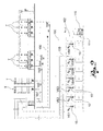
- the transport system 1 may be both of the "local” type, that is constructed to connect one single processing machine to one single storage container, and of the centralised “type", that is constructed to connect two or more processing machines to two or more storage containers, as illustrated in particular in Figure 2 .
- the loading device 10 may consist of both a feeder and a receiver.
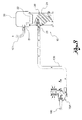
- the processing system comprises a storage container T of granular material G to be transferred to a processing machine M.
- the pneumatic transport system 1 comprises a fluidifying lance 2 which draws in the granular material G, consisting, for example, of a substantially rigid pipe, aimed at catching granules of material and mixing them with air.
- the lance 2 is in a fluid communication with an end of a conveying duct 100, which may be of both the rigid and the flexible type and whose end penetrates an intermediate portion of a tightly sealed loading device 10 (in this specific case, a receiver) and defines a discharge outlet.
- a collection tank 20 of the granular material is installed inside the loading device 10, at a lower level than that of the discharge outlet.
- the tank 20 consists of a dosing hopper provided with a lower discharge outlet which may be opened and closed by a bottom supported by a projecting arm in order to oscillate around a horizontal axis.
- the swivel equipment made up of the bottom 24 and the support arm 25, is provided with a counterweight 26 which encloses a magnet and an electro-magnetic alignment sensor 27.
- the bottom automatically closes the discharge outlet of the hopper 20, thanks to the presence of the counterweight 26 and of vacuum.
- the magnet enclosed in the counterweight aligns to the magnetic sensor 27 generating an electrical signal, which is sent to an electronic control unit.
- the transport air of the granular material G coming from the container T separates from the granular material falling within the tank 20 and is drawn, optionally through a first filter 28, from an outlet 29 which is made in the upper portion or head 30 of the receiver 10 and is in fluid communication with an end of a duct 101.
- the other end of the duct 101 leads to a cyclone filtering assembly 31.
- a further flexible duct 102 departs which is connected to a vacuum source 110, typically at the suction outlet of a vacuum pump or a blower, which provides for the ejection of the air drawn through the ducts 100, 101 and 102 directly in the ambient air, for example by a duct 103.
- the discharge outlet of the hopper 20 opens - by the effect of the lack of vacuum and the weight of the granular material contained therein - allowing the granular material to be discharged in an underlying feeding hopper 34 of the machine M.
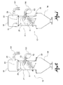
- FIG. 2 A example of processing system with a centralized transport system under vacuum is illustrated in Figure 2 .
- processing machines M1-Mn each provided with its own loading device 10 (consisting of a receiver), and a plurality of storage containers T of material (for example silos), which may contain different granular materials.
- the various receivers 10 are in fluid communication with the filtering assembly 111 by means of a common duct 102, in jargon referred to as "vacuum line".
- Each receiver is in fluid communication with the different storage containers by means of a conveying duct 100.
- the system is provided with a switching apparatus of the conveying lines so that it is possible to connect the conveying line of a receiver to different storage containers alternatively.
- the receivers 10 are each provided with an on-off valve 35 (referred to as vacuum breaker) located inside the respective head 10.
- the vacuum breaker valve 35 is part of the above-mentioned means for generating vacuum, and as such may be piloted in combination with or as an alternative to the vacuum source 110 (blower or pump) to activate or suspend the flow of material towards the loading device 10.
- the vacuum breaker valve 35 may be piloted by a respective electro-pneumatic valve VE1,..,VEn in turn controlled by a suitable electronic control unit (not illustrated in the Figures) aimed at managing each area of the system, in particular providing for the actuation of one receiver first and then the other depending on the operating requirements.
- the conveying line 100 is affected by a predetermined amount of air and of granular material and at the end of each cycle it is completely discharged of granular material, thanks to the presence of an intercepting device, referred to as "duct cleaning valve", Vp1,..,Vpn, provided for each receiver, so that when the suction unit 110 stops or the vacuum breaker valve 25 is actuated for the receiver of interest, the conveying line 100 is emptied.
- Figure 3 shown a typical cleaning valve referred to as VP1 inserted in the conveying duct 100 of a respective receiver 10.
- VP1 typical cleaning valve
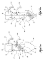
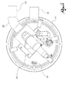
- the pneumatic transport system 1 comprises for each loading device (be it a receiver or a feeder) at least one sensor 51, 52 to detect the vibrations induced by the material which is being loaded into the loading device 10.
- such at least one sensor 51, 52 is arranged at the loading device 10.
- the sensor 51, 52 may also be arranged in the proximity of the loading device 10, provided that the sensor is capable of detecting the vibrations induced on the loading device by the granular material which is being loaded into the device itself.
- Such sensor 51, 52 generates time signals of the vibrations which - as will be further explained hereinafter by describing the method according to the present invention - may be correlated to the mass of granular material which is being progressively loaded into the collection tank 20.
- such sensor 51, 52 generates time signals of the vibrations which may be correlated to the volumes of the collection tank 20 being progressively filled with granular material.
- the transport system 1 comprises at least one electronic control unit (not illustrated in the annexed
- the electronic control unit progressively estimates over time the filled level of the collection tank 20 of the loading device, correlating to the above-mentioned signals the mass of granular material G loaded in the tank 20 by means of a modal analysis of the same signals, as will be further explained in the following description.
- the electronic control unit estimates progressively over time the filled level of the collection tank 20 of the loading device, correlating to the above-mentioned signals the volume of the collection tank 20 being progressively filled with the granular material depending on variations of frequency and/or amplitude of such signals.
- the electronic control unit controls the flow generating means 110, 35 to activate or suspend the flow of material towards the loading device depending on the estimated filled level of the tank so as to optimise the filling time of the tank.
- the electronic control unit optimises the filling time of the tank 20 dividing it into one or more loading steps of the granular material, wherein the material conveyed to the tank is taken directly from the storage container T, and one or more cleaning steps of the conveyor duct 100, wherein the material conveyed to the tank is composed of any residues remaining in the conveying duct.
- the electronic control unit may store - for each filling cycle - the total filling time of the collection tank, the time of the loading step and/or the time of the cleaning step, so as to create a set of statistical parameters.
- the control unit may therefore generate an alarm signal whenever one or more of the filling time, the loading time and/or the cleaning time in a specific cycle do not fall within the above-mentioned statistical parameters.
- the above-mentioned at least one sensor 51, 52 may be arranged in any position, provided that it is at or in the proximity of the loading device 10, with the above described clarification.
- the senor 51, 52 is arranged on the outside, and not on the inside, of the collection tank to prevent it from being directly hit by the granular material. This may reduce its measurement accuracy.
- the above-mentioned at least one sensor 51, 52 may be connected to a containment wall 21 of the collection tank 20 of the loading device, for example on the lateral wall (in particular being cylindrical in shape).
- the sensor may also be directly installed in the electronic control board of the loading device.
- the loading device 10 is provided with an upper lid 22 closing the collection tank.
- Such lid separates the collection tank from the upper portion of the loading device (known in the jargon as upper head and indicated as 30 in the figures).
- such lid may carry a filter 28.
- the above-mentioned at least one sensor 51, 52 may be connected to the lid 22.
- the sensor 51 is arranged on the side of the lid 22 facing the head 30, that is inside the volume defined by the head 30.
- the loading device 10 is provided with a tubular element 23 which allows the connection with the conveying duct 100.
- such connector element 23 passes through a wall of the collection tank 20 and is attached thereto.
- the above-mentioned at least one sensor 52 may be connected to such tubular connector element 23, preferably as close as possible to the wall of the tank.
- the transport system 1 may also comprise for the single loading device two or more sensors 51 and 52 for detecting vibrations, arranged at different positions in the proximity of and/or at the loading device.
- the use of two or more sensors allows reducing the error margin, correlating multiple signals.
- the above-mentioned at least one sensor 51 or 52 may be an accelerometer.
- the accelerometer may be of any suitable type.
- it may be of the capacitive type, which takes advantage, as a principle, of the variation of electrical capacity of a condenser upon variation of the distance between the armatures thereof.
- the mass constitutes an armature, while the other is obtained on a fixed structure of the device, in the immediate vicinity of the mass.
- the above-mentioned at least one sensor 51 or 52 may be a velocimeter.
- the above-mentioned at least one sensor 51 or 52 may be a transducer of an electromechanical type, preferably a microphone.
- control method comprises a step a) of providing:
- the method further comprises the following operating steps:
- time signals are correlated to the mass of granular material being progressively loaded.
- the assembly given by the loading device and the mass of granular material being progressively loaded inside the device has one or more proper frequencies.
- the frequency and amplitude of such time signals of the vibrations generated by the sensor vary upon variation of the mass of loaded granular material.
- the mass of material being progressively loaded is estimated based on the time variations of the amplitude and/or frequency of said signals.
- the filled level may be calculated from the estimated value of the mass of loaded granular material.
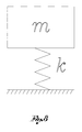
- Figure 8 shows a simple mathematical model consisting of a mass m connected to a spring with elastic constant k.
- the illustrated system if stressed, starts oscillating with a well-precise frequency especially connected to the values of mass and elastic constant of the spring.
- Real objects although more complex than the simple system illustrated herein, have similar behaviours to that just described. More specifically, they are characterised by a set of proper frequencies, each provided with the relative damping and its proper modal form.
- the inner force acts on the structure of the loading device, caused by the impact of the granular material, it provides energy to one of these frequencies.
- the senor 51, 52 is an accelerometer.
- the amplitude of the signal and the frequency of the signal vary.
- a specific algorithm implemented for example by the already mentioned electronic control unit
- the method may comprise a cleaning step f) of the conveying duct 100.
- this step (described hereinabove) an air flow directed towards the tank 20 is generated inside the duct to free it from any residues of material.
- cleaning step f) is carried out after the loading step d).
- the filling time is optimised in the above-mentioned step e) of the method as a sum of the times of the loading step b) and the cleaning step f) of the duct.
- the method comprises a step g) of storing - for each filling cycle - the total filling time of the collection tank, the time of the loading step and/or the time of the cleaning step.
- a step g) of storing - for each filling cycle - the total filling time of the collection tank, the time of the loading step and/or the time of the cleaning step is possible to create a set of statistical parameters.
- the method may provide for a step h) of generating an alarm signal whenever one or more of the filling time, the loading time and/or the cleaning time in a specific cycle do not fall within the above-mentioned statistical parameters.
- the present invention allows to control and adjust in an automated and efficient way - upon variation of the operating conditions - a pneumatic transport system. Thanks to the invention it is in fact possible to control and adjust in an automated way the filling of the collection tank of one or more loading devices, avoiding any manual operation by the operators.
- the filled level of the tank may be monitored in real time. This enables a greater optimisation of the system operation. It is in fact possible to operate on the system almost immediately upon occurrence of any variation of the operating conditions.
- the invention it is possible to significantly reduce the operating costs as compared to the conventional systems.
- the start-up steps of a system - which normally require a set of tests carried out manually by the operators - may be carried out in an automated way by the system, in a shorter time, with less waste of material. Globally, also the system downtime is reduced.
- the system according to the invention is capable of autonomously learning, without any operation by the operator, during both the start-up and normal operation.
- the system may further store a set of statistical parameters related to the actual filling time of all the receivers of the pneumatic transport system. In this way, if a filling cycle has loading and/or duct cleaning times which fall outside the statistical values stored in the control unit, the system will notify an ongoing anomaly for any problems along the transport duct or of lack of material, for example by means of an alarm.
- the invention does not require substantial modifications to the transport system. It may therefore be considered as simple and inexpensive to manufacture. The invention is therefore suitable for retrofitting interventions to pre-existing systems.
Landscapes
- Engineering & Computer Science (AREA)
- Mechanical Engineering (AREA)
- Filling Or Emptying Of Bunkers, Hoppers, And Tanks (AREA)
- Air Transport Of Granular Materials (AREA)
- Sampling And Sample Adjustment (AREA)
Claims (16)
- Pneumatisches Transportsystem für Granulatmaterial bzw. körniges Material, das dazu bestimmt ist, körniges Material von einem oder mehreren Lagerbehälter (T) zu einer oder mehreren Bearbeitungsmaschinen (M) zu fördern, das Folgendes umfasst:- mindestens eine Ladevorrichtung (10) für das körnige Material, die einer Bearbeitungsmaschine (M) zuzuordnen ist, um sie mit körnigem Material zu versorgen, wobei die genannte Vorrichtung mit einem Sammeltank (20) für das körnige Material ausgestattet wird;- mindestens einen Förderkanal (100) für körniges Material, der den Sammeltank mit mindestens einem Lagerbehälter (T) für körniges Material fluidisch miteinander verbindet, um solch ein Material vom Behälter in einen derartigen Tank zu transferieren; und- Mittel (110, 35), um innerhalb des Förderkanals (100) eine Strömung aus körnigem Material vom Lagerbehälter (T) zum Sammeltank (20) der Ladevorrichtung zu erzeugen,dadurch gekennzeichnet, dass es für jede Ladevorrichtung mindestens einen Sensor (51, 52) umfasst, um die Vibrationen zu erfassen, die durch das Material hervorgerufen werden, das innerhalb der Ladevorrichtung (10) geladen wird, wobei der genannte mindestens eine Sensor (51, 52) in der Nähe oder im Bereich der Ladevorrichtung positioniert wird und Zeitsignale der Vibrationen erzeugt, die mit der Masse von körnigem Material korreliert werden können, das allmählich in den Sammeltank (20) geladen wird, oder mit dem Volumen des zunehmend mit dem genannten körnigen Material gefüllten Sammeltanks (20) korreliert werden können, wobei das genannte System mindestens eine elektronische Steuereinheit umfasst, die mit dem genannten mindestens einen Sensor (51, 52) verbunden wird, um die Zeitsignale der Vibrationen zu empfangen, die er erzeugt, wobei die genannte elektronische Steuereinheit über die Zeit den Füllstand des Sammeltanks nach und nach schätzt, wobei sie mit den genannten Signalen die Masse des in den Tank geladenen körnigen Materials korreliert mittels einer Modalanalyse der genannten Signale oder indem sie mit Variationen in der Frequenz und/oder in der Amplitude der genannten Signale das Volumen des sich zunehmend mit körnigem Material füllenden Sammeltanks (20) korreliert, wobei die genannte elektronische Steuereinheit die strömungserzeugenden Mittel (110, 35) steuert, um den Materialstrom hin zur Ladevorrichtung entsprechend dem geschätzten Füllstand des Tanks zu aktivieren oder auszusetzen, um die Füllzeit des Tanks zu optimieren.
- System nach Anspruch 1, wobei die genannte elektronische Steuereinheit die Füllzeit des Tanks (20) optimiert, indem diese in eine oder mehrere Ladephasen des körnigen Materials aufgeteilt wird, in denen das zum Tank geförderte Material direkt vom Lagerbehälter (T) genommen wird, und in eine oder mehrere Reinigungsphasen des Förderkanals (100) aufgeteilt wird, in denen das zum Tank geförderte Material aus möglichen Rückständen zusammengesetzt ist, die im Förderkanal verblieben sind.
- System nach Anspruch 1 oder 2, wobei die genannte elektronische Steuereinheit die Füllzeit des Sammeltanks für jeden Füllzyklus speichert, wobei eine Reihe von statistischen Parametern erzeugt werden, wobei die genannte Steuereinheit ein Alarmsignal erzeugt, falls die Füllzeit in einem spezifischen Zyklus nicht innerhalb der zuvor genannten statistischen Parameter fällt.
- System nach einem oder mehreren der Ansprüche von 1 bis 3, wobei der genannte mindestens eine Sensor (51, 52) mit einer Eingrenzungswand (21) des Sammeltanks der Ladevorrichtung verbunden ist.
- System nach einem oder mehreren der Ansprüche von 1 bis 3, wobei die genannte mindestens eine Ladevorrichtung (10) mit einem oberen Deckel (22) ausgestattet ist, der den Sammeltank verschließt, wobei der genannte mindestens eine Sensor (51, 52) mit dem genannten Deckel (22) verbunden ist.
- System nach einem oder mehreren der Ansprüche von 1 bis 3, wobei die genannte mindestens eine Ladevorrichtung (10) mit einem rohrförmigen Element (23) der Verbindung mit dem genannten Förderkanal (100), wobei das genannte Verbindungselement (23) eine Wand des genannten Sammeltanks durchquert und an dieser befestigt ist, wobei der genannte mindestens eine Sensor (51, 52) mit dem genannten rohrförmigen Element (23) verbunden ist.
- System nach einem oder mehreren der vorhergehenden Ansprüche, das zwei oder mehrere Sensoren (51, 52) zur Erfassung von Vibrationen umfasst, die in unterschiedlichen Stellen, in der Nähe und/oder im Bereich der Ladevorrichtung positioniert sind.
- System nach einem oder mehreren der vorhergehenden Ansprüche, wobei der genannte mindestens eine Sensor (51, 52) ein Beschleunigungsmesser ist.
- System nach einem oder mehreren der Ansprüche von 1 bis 7, wobei der genannte mindestens eine Sensor (51, 52) ein Geschwindigkeitsmesser ist.
- System nach einem oder mehreren der Ansprüche von 1 bis 7, wobei der genannte mindestens eine Sensor (51, 52) ein Wandler elektromechanischer Art ist, vorzugsweise ein Mikrofon.
- Ein Steuerverfahren eines pneumatischen Transportsystems für körniges Material, das die folgenden Arbeitsschritte umfasst:a) vorbereiten: - mindestens eine Vorrichtung (10) zum Laden des körnigen Materials für eine Bearbeitungsmaschine (M), wobei die genannte Vorrichtung mit einem Sammeltank (20) für das körnige Material ausgestattet wird; - mindestens einen Förderkanal (100) für körniges Material, der den Sammeltank mit mindestens einem Behälter (T) zur Lagerung von körnigem Material fluidisch miteinander verbindet; und - Mittel (110, 35), um innerhalb des Förderkanals (100) eine Strömung aus körnigem Material vom Lagerbehälter (T) zum Sammeltank (20) der Ladevorrichtung zu erzeugen;b) laden des Tanks (20) mit dem genannten Material, was eine Strömung aus körnigem Material vom Behälter (T) zum Tank (20) erzeugt;c) erfassen mittels eines Sensors (51, 52) der Vibrationen, die innerhalb der Ladevorrichtung (10) durch das körnige Material hervorgerufen werden, das in solch einer Vorrichtung geladen wird, wobei Zeitsignale erzeugt werden; undd) schätzen, stetig über die Zeit, des Füllstandes des Sammeltanks (20), wobei mit den genannten Zeitsignalen der Vibrationen die Masse des in den Tank geladenen körnigen Materials korreliert wird, mittels einer Modalanalyse der genannten Signale, oder das Volumen des sich zunehmend mit dem genannten körnigen Material füllenden Sammeltanks (20) korreliert wird, auf der Grundlage von Variationen in der Frequenz und/oder in der Amplitude der genannten Signale; unde) steuern des strömungserzeugenden Mittels (110, 35), um den Materialstrom hin zur Ladevorrichtung (10) entsprechend dem geschätzten Füllstand des Tanks (20) zu aktivieren oder auszusetzen, um die Füllzeit des Tanks zu optimieren.
- Verfahren nach Anspruch 11, wobei die durch die Ladevorrichtung und durch die Masse an körnigem Material, die nach und nach in die Vorrichtung geladen wird, vorgegebene Zusammenstellung eine oder mehrere spezifische Frequenzen aufweist, wobei die Frequenz und die Amplitude der genannten, durch die Sensoren erzeugten, Vibrations-Zeitsignale mit der Variation der Masse des geladenen körnigen Materials variieren, wobei im Schritt d) der Schätzung des Füllstandes, die Masse an nach und nach geladenem Material geschätzt wird auf der Grundlage von Zeitvariationen der Amplitude und/oder Frequenz der genannten Signale, wobei das Volumen des Sammeltanks und die Dichte des körnigen Materials bekannt sind, wobei der Füllstand aus dem Schätzwert der Masse an geladenem Material berechenbar ist.
- Verfahren nach Anspruch 11 oder 12, umfassend einen Schritt f) der Förderkanal (100) - Säuberung, wobei eine Luftströmung in Richtung Tank (20) im Kanal erzeugt wird, um ihn von möglichen Material-Rückständen zu befreien.
- Verfahren nach Anspruch 13, wobei der genannte Säuberungs-Schritt f) nach dem Lade-Schritt b) vorgenommen wird, wobei die Füllzeit als Summe der Zeiten des Lade-Schritts b) und des Säuberungs-Schritts f) des Förderkanals im genannten Schritt e) optimiert wird.
- Verfahren nach einem oder mehreren der Ansprüche von 11 bis 14, umfassend einen Schritt g) der Speicherung der Sammeltank-Füllzeit für jeden Füllzyklus, wobei eine Reihe von statistischen Parametern erzeugt werden.
- Verfahren nach Anspruch 15, umfassend einen Schritt h) der Erzeugung eines Alarmsignals, falls die Füllzeit in einem spezifischen Zyklus nicht innerhalb der zuvor genannten statistischen Parameter fällt.
Applications Claiming Priority (1)
| Application Number | Priority Date | Filing Date | Title |
|---|---|---|---|
| IT000142A ITPD20130142A1 (it) | 2013-05-22 | 2013-05-22 | Sistema di trasporto pneumatico di materiale granulare e metodo di controlllo di tale sistema |
Publications (2)
| Publication Number | Publication Date |
|---|---|
| EP2805902A1 EP2805902A1 (de) | 2014-11-26 |
| EP2805902B1 true EP2805902B1 (de) | 2016-01-13 |
Family
ID=48832980
Family Applications (1)
| Application Number | Title | Priority Date | Filing Date |
|---|---|---|---|
| EP14167582.7A Active EP2805902B1 (de) | 2013-05-22 | 2014-05-08 | Pneumatisches Transportsystem für Granulatmaterial und Steuerverfahren eines solchen Systems |
Country Status (6)
| Country | Link |
|---|---|
| US (1) | US9637320B2 (de) |
| EP (1) | EP2805902B1 (de) |
| JP (1) | JP6454085B2 (de) |
| KR (1) | KR102172370B1 (de) |
| CN (1) | CN104176506B (de) |
| IT (1) | ITPD20130142A1 (de) |
Families Citing this family (45)
| Publication number | Priority date | Publication date | Assignee | Title |
|---|---|---|---|---|
| US9731914B2 (en) * | 2008-11-06 | 2017-08-15 | Michael J. Rasner | Pneumatic convey system with constant velocity pickup |
| RU2502661C1 (ru) * | 2012-08-27 | 2013-12-27 | Закрытое Акционерное Общество "Твин Трейдинг Компани" | Способ вакуумно-пневматического транспортирования сыпучих материалов с высокой массовой концентрацией |
| RU2535821C1 (ru) * | 2013-10-31 | 2014-12-20 | Закрытое Акционерное Общество "Твин Трейдинг Компани" | Вакуумно-пневматическое устройство для транспортирования сыпучих материалов с высокой массовой концентрацией |
| US9937651B2 (en) | 2014-02-20 | 2018-04-10 | Novatec, Inc. | Resin delivery apparatus and method with plural air flow limiters |
| US10175701B2 (en) | 2014-02-20 | 2019-01-08 | Stephen B. Maguire | Air flow regulator with detector and method for regulating air flow |
| US10144598B2 (en) | 2014-02-20 | 2018-12-04 | Novatec, Inc. | Variable frequency drive combined with flow limiter set for limiting flow to selected level above design choice |
| US10179708B2 (en) | 2014-02-20 | 2019-01-15 | Maguire Products, Inc. | Granular material delivery system with air flow limiter |
| US10414083B2 (en) | 2014-02-20 | 2019-09-17 | Novatec, Inc. | Multiple sensor resin delivery optimizing vacuum pump operation |
| US10280015B2 (en) | 2014-02-20 | 2019-05-07 | Stephen B. Maguire | Method for adjustably restricting air flow and apparatus therefor |
| US10131506B2 (en) | 2014-12-09 | 2018-11-20 | Maguire Products, Inc. | Selective matrix conveyance apparatus and methods for granular resin material |
| US10179696B2 (en) | 2015-01-27 | 2019-01-15 | Novatec, Inc. | Variable opening slide gate for regulating material flow into airstream |
| EP3256383A4 (de) * | 2015-02-12 | 2018-10-03 | IPEG, Inc. | Automatisierte vakuumbetätigte steuerung |
| US10138076B2 (en) | 2015-02-25 | 2018-11-27 | Stephen B. Maguire | Method for resin delivery including metering introduction of external air to maintain desired vacuum level |
| MX2017011998A (es) * | 2015-03-19 | 2018-06-07 | Ipeg Inc | Metodo de prueba de diferencial de presion para transporte neumatico. |
| US10507605B2 (en) | 2015-05-14 | 2019-12-17 | Wittmann Battenfeld Canada Inc. | Method and system of vacuum loading |
| JP2017024882A (ja) * | 2015-07-27 | 2017-02-02 | 株式会社松井製作所 | 粉粒体材料の供給装置 |
| DE102016007061A1 (de) * | 2016-06-03 | 2017-12-07 | Walter Kramer | Förderanlage für Schüttgut, insbesondere Kunststoffgranulat, und Verfahren zum Fördern von Schüttgut, insbesondere Kunststoffgranulat |
| NO343343B1 (en) * | 2016-11-21 | 2019-02-04 | Norsk Hydro As | Apparatus and method for feeding doses of fluidisable materials |
| US10759595B2 (en) * | 2017-03-03 | 2020-09-01 | The Modern Group, Ltd. | Roll-off transport barrel with gravity, vacuum, and pneumatic loading and unloading |
| EP3406547B1 (de) * | 2017-05-23 | 2020-08-05 | Piab Ab | Filterüberwachung in pneumatischen transportsystemen |
| EP3530599A1 (de) * | 2018-02-27 | 2019-08-28 | Piab Ab | Vakuumförderanlage |
| CA3038323A1 (en) * | 2018-03-28 | 2019-09-28 | Ipeg, Inc. | System and method using telemetry to configure control systems for pneumatic conveying systems |
| MX2019003718A (es) * | 2018-03-28 | 2019-09-30 | Ipeg Inc | Sistema y metodo que utiliza telemetria para caracterizar, mantener y analizar sistemas de transporte neumatico. |
| JP6541863B1 (ja) * | 2018-11-29 | 2019-07-10 | 株式会社ソディック | 食品材料粉体の供給装置 |
| DE102019001471A1 (de) | 2019-02-27 | 2020-08-27 | Walter Kramer | Saugfördersystem für Schüttgut, insbesondere Kunststoffgranulat |
| KR102736658B1 (ko) * | 2019-03-06 | 2024-12-02 | 에스케이온 주식회사 | 진공 컨베이어를 이용한 분체 자동 이송 시스템 |
| US10994945B2 (en) | 2019-09-18 | 2021-05-04 | Plastrac Inc. | Granular metering system |
| KR102063424B1 (ko) * | 2019-10-11 | 2020-01-07 | 지성배 | 분말 수집장치 |
| US11365071B2 (en) * | 2020-04-28 | 2022-06-21 | IPEG, Inc | Automatic tuning system for pneumatic material conveying systems |
| JP7100405B1 (ja) * | 2020-11-03 | 2022-07-13 | 株式会社ツカサ | 粉体供給装置 |
| FI130331B (fi) * | 2021-03-08 | 2023-06-21 | Maricap Oy | Menetelmä materiaalin siirtämiseksi ja materiaalinsiirtojärjestely |
| US12193627B2 (en) | 2021-07-08 | 2025-01-14 | Industrial Vacuum Transfer Services Usa, Llc | High volume industrial vacuum assemblies and methods |
| US12137864B2 (en) | 2021-07-08 | 2024-11-12 | Industrial Vacuum Transfer Services Usa, Llc | Assemblies and methods for material extraction |
| US12485459B2 (en) | 2021-07-08 | 2025-12-02 | Industrial Vacuum Transfer Services Usa, Llc | Systems, assemblies, and methods for pyrophoric material extraction |
| US12091264B2 (en) | 2021-07-08 | 2024-09-17 | Industrial Vacuum Transfer Services Usa, Llc | Assemblies, apparatuses, systems, and methods for material extraction and conveyance |
| WO2023283632A1 (en) * | 2021-07-08 | 2023-01-12 | Industrial Vacuum Transfer Services Usa, Llc | High volume industrial vacuum assemblies and methods |
| US12510077B2 (en) | 2021-07-08 | 2025-12-30 | Industrial Vacuum Transfer Services Usa, Llc | Air compressor having vacuum and associated methods for loading and extracting materials |
| US12098068B2 (en) | 2021-07-08 | 2024-09-24 | Industrial Vacuum Transfer Services Usa, Llc | Systems, methods, and devices for industrial tower waste extraction |
| US12103791B2 (en) | 2021-07-08 | 2024-10-01 | Industrial Vacuum Transfer Services Usa, Llc | Assemblies and methods for material extraction from retention collections |
| US12246932B2 (en) | 2021-07-08 | 2025-03-11 | Industrial Vacuum Transfer Services Usa, Llc | Methods for loading and extracting product in elevated tower |
| CN216736366U (zh) * | 2021-09-28 | 2022-06-14 | 宁德时代新能源科技股份有限公司 | 一种吸枪及吸料装置 |
| CN114194833B (zh) * | 2021-12-08 | 2023-08-22 | 晋江力绿食品有限公司 | 海苔膨化食品生产用真空送料系统 |
| CN115465687B (zh) * | 2022-09-16 | 2025-11-04 | 南华大学 | 放射性粉末物料汇集总成 |
| IT202300018756A1 (it) * | 2023-09-13 | 2025-03-13 | Grafenix S R L | Apparecchiatura e metodo per trasferire particelle volatili di materiale solido tra due contenitori. |
| CN117465919B (zh) * | 2023-12-26 | 2024-02-23 | 睢宁县泰宁建材有限公司 | 一种粉末状物料输送智能监测控制方法 |
Family Cites Families (29)
| Publication number | Priority date | Publication date | Assignee | Title |
|---|---|---|---|---|
| FR1187944A (fr) * | 1958-02-18 | 1959-09-17 | Bailey Controle | Dispositif de détection de l'arrêt d'un courant de matières solides s'écoulant à travers une canalisation |
| JPS4820589B1 (de) * | 1970-03-12 | 1973-06-22 | ||
| US3937521A (en) * | 1970-12-16 | 1976-02-10 | Consolidated Engineering Company | Self-purging pneumatic conveying apparatus and varied means of operation |
| US4252001A (en) * | 1977-01-21 | 1981-02-24 | Musschoot A | Method and apparatus for cooling foundry sand |
| US4221507A (en) * | 1977-11-04 | 1980-09-09 | Atlas Powder Company | Microbubble feeding apparatus and method |
| US4718795A (en) * | 1982-02-18 | 1988-01-12 | Acf Industries, Incorporated | Unloading outlet assembly |
| US4844663A (en) * | 1987-09-18 | 1989-07-04 | Shell Oil Company | Feed line-ultrasonic activated gas injection |
| US4907892A (en) * | 1989-02-02 | 1990-03-13 | Fuller Company | Method and apparatus for filling, blending and withdrawing solid particulate material from a vessel |
| US5378089A (en) * | 1993-03-01 | 1995-01-03 | Law; R. Thomas | Apparatus for automatically feeding hot melt tanks |
| US5558472A (en) * | 1993-10-07 | 1996-09-24 | Sumitomo Chemical Company, Limited | Method and apparatus for transporting particles |
| JP3732614B2 (ja) * | 1996-06-06 | 2006-01-05 | 大和製衡株式会社 | 定量秤 |
| JPH1183594A (ja) * | 1997-09-04 | 1999-03-26 | Ono Sokki Co Ltd | 測定装置 |
| CH692854A5 (de) * | 1997-11-21 | 2002-11-29 | Gericke Ag | Verfahren zum Betrieb einer Pfropfenförderanlage sowie Pfropfenförderanlage zur Durchführung des Verfahrens. |
| GB2334958B (en) * | 1998-02-25 | 2001-11-07 | Porpoise Viscometers Ltd | Melt flow index determination in polymer process control |
| DE19912277A1 (de) * | 1999-03-18 | 2000-09-21 | Mann & Hummel Protec Gmbh | Einrichtung zum Fördern von Kunststoffgranulat |
| DE10039564B4 (de) * | 2000-08-12 | 2009-11-05 | Mann + Hummel Protec Gmbh | Vorrichtung zum Fördern von Schüttgut |
| WO2005058707A2 (en) * | 2003-12-15 | 2005-06-30 | Polymer Group, Inc. | Unitized fibrous construct dispensing system |
| EP1780154B1 (de) * | 2005-11-01 | 2009-07-01 | Sun Chemical B.V. | Verfahren und Vorrichtung zur Vakuumförderung von Schüttgut |
| GB0523338D0 (en) * | 2005-11-16 | 2005-12-28 | Inbulk Technologies Ltd | Vacuum conveying velocity control device |
| WO2007139106A1 (ja) * | 2006-05-31 | 2007-12-06 | Sintokogio, Ltd. | 加圧タンク、粉体の輸送管への送込み装置およびその送込み方法、並びに粉体の輸送管への送込み間隔の決定方法 |
| ITVR20070083A1 (it) * | 2007-06-12 | 2008-12-13 | Moretto Spa | Impianto per il trasporto pneumatico a velocita' controllata di materiale granulare e procedimento di controllo della velocita' di convogliamento |
| FI20085146A7 (fi) * | 2007-12-21 | 2009-06-22 | Maricap Oy | Menetelmä ja laitteisto pneumaattisessa materiaalinsiirtojärjestelmässä |
| KR101116365B1 (ko) * | 2009-08-12 | 2012-03-09 | 한국전력공사 | 정전유도형 이젝터 마찰대전기를 이용한 석탄회 중 미연탄소의 정전분리장치 |
| US9045072B2 (en) * | 2009-11-02 | 2015-06-02 | Super Products Llc | Debris level indicator in vacuum loaded mobile tanks |
| US8893723B2 (en) * | 2010-01-07 | 2014-11-25 | Hauni Maschinenbau Ag | Method and device for removing foreign particles from a tobacco stream |
| US20140042060A1 (en) * | 2012-08-09 | 2014-02-13 | Gary L. Stevenson | Hydrocarbon reclamation method and assembly |
| RU2502661C1 (ru) * | 2012-08-27 | 2013-12-27 | Закрытое Акционерное Общество "Твин Трейдинг Компани" | Способ вакуумно-пневматического транспортирования сыпучих материалов с высокой массовой концентрацией |
| DE102013010048A1 (de) * | 2013-06-17 | 2014-12-18 | Haver & Boecker Ohg | Packmaschine und Verfahren |
| JP2015175950A (ja) * | 2014-03-14 | 2015-10-05 | 株式会社リコー | 貯留設備及びトナー製造装置 |
-
2013
- 2013-05-22 IT IT000142A patent/ITPD20130142A1/it unknown
-
2014
- 2014-05-08 EP EP14167582.7A patent/EP2805902B1/de active Active
- 2014-05-16 US US14/280,078 patent/US9637320B2/en active Active
- 2014-05-19 JP JP2014103679A patent/JP6454085B2/ja not_active Expired - Fee Related
- 2014-05-22 KR KR1020140061666A patent/KR102172370B1/ko not_active Expired - Fee Related
- 2014-05-22 CN CN201410219163.9A patent/CN104176506B/zh not_active Expired - Fee Related
Also Published As
| Publication number | Publication date |
|---|---|
| KR20140137323A (ko) | 2014-12-02 |
| JP6454085B2 (ja) | 2019-01-16 |
| CN104176506A (zh) | 2014-12-03 |
| US20140348597A1 (en) | 2014-11-27 |
| CN104176506B (zh) | 2017-12-12 |
| EP2805902A1 (de) | 2014-11-26 |
| JP2014227302A (ja) | 2014-12-08 |
| KR102172370B1 (ko) | 2020-11-02 |
| US9637320B2 (en) | 2017-05-02 |
| ITPD20130142A1 (it) | 2014-11-23 |
Similar Documents
| Publication | Publication Date | Title |
|---|---|---|
| EP2805902B1 (de) | Pneumatisches Transportsystem für Granulatmaterial und Steuerverfahren eines solchen Systems | |
| US20230002087A1 (en) | Slide measuring system for filling pouches and associated method | |
| US9266628B2 (en) | Device and method for metering a bulk material | |
| CN104039653A (zh) | 用于灌装袋的包装机以及方法 | |
| US10661921B2 (en) | Apparatus and method for filling an open container | |
| CN102564539A (zh) | 称重剔除机 | |
| CN106742124B (zh) | 一种碳酸钙粉吨袋包装系统及包装方法 | |
| CN105857656B (zh) | 全自动袋式包装柔性生产线 | |
| US20160334264A1 (en) | Apparatus and Method for Conveying Flowable Materials, In Particular Bulk Materials | |
| CN108583950A (zh) | 定量包装控制系统及控制方法 | |
| CN101508388B (zh) | 粒状高分子树脂在线秤重计量给料系统及给料方法 | |
| CN103979124A (zh) | 一种无间歇高速数粒仪 | |
| CN103935741B (zh) | 一种可控出料装置系统及方法 | |
| JP2007126290A (ja) | コンベア配送システム | |
| CN101687554B (zh) | 包装机 | |
| US11953360B1 (en) | Flow measuring and metering device for flowable granular solids | |
| CN206417227U (zh) | 一种能顺利出料的定量颗粒分装机 | |
| CN103043446B (zh) | 气力输送系统的输气间隔确定方法及系统 | |
| CN204433094U (zh) | 饲料装袋机 | |
| US20040071928A1 (en) | Device for bagging bulk material | |
| CN210133703U (zh) | 一种粒状高分子树脂精准计量给料系统 | |
| CN208119881U (zh) | 一种可控量出料的出料装置 | |
| CN213168620U (zh) | 收尘灰自动装袋装置 | |
| CN219187970U (zh) | 一种数粒机强效联动在线除尘装置 | |
| CN205633108U (zh) | 一种砂浆粉料的包装机 |
Legal Events
| Date | Code | Title | Description |
|---|---|---|---|
| PUAI | Public reference made under article 153(3) epc to a published international application that has entered the european phase |
Free format text: ORIGINAL CODE: 0009012 |
|
| 17P | Request for examination filed |
Effective date: 20140508 |
|
| AK | Designated contracting states |
Kind code of ref document: A1 Designated state(s): AL AT BE BG CH CY CZ DE DK EE ES FI FR GB GR HR HU IE IS IT LI LT LU LV MC MK MT NL NO PL PT RO RS SE SI SK SM TR |
|
| AX | Request for extension of the european patent |
Extension state: BA ME |
|
| R17P | Request for examination filed (corrected) |
Effective date: 20150521 |
|
| RBV | Designated contracting states (corrected) |
Designated state(s): AL AT BE BG CH CY CZ DE DK EE ES FI FR GB GR HR HU IE IS IT LI LT LU LV MC MK MT NL NO PL PT RO RS SE SI SK SM TR |
|
| GRAP | Despatch of communication of intention to grant a patent |
Free format text: ORIGINAL CODE: EPIDOSNIGR1 |
|
| INTG | Intention to grant announced |
Effective date: 20150731 |
|
| RAP1 | Party data changed (applicant data changed or rights of an application transferred) |
Owner name: MORETTO S.P.A. |
|
| RIN1 | Information on inventor provided before grant (corrected) |
Inventor name: MORETTO, RENATO |
|
| GRAS | Grant fee paid |
Free format text: ORIGINAL CODE: EPIDOSNIGR3 |
|
| GRAA | (expected) grant |
Free format text: ORIGINAL CODE: 0009210 |
|
| AK | Designated contracting states |
Kind code of ref document: B1 Designated state(s): AL AT BE BG CH CY CZ DE DK EE ES FI FR GB GR HR HU IE IS IT LI LT LU LV MC MK MT NL NO PL PT RO RS SE SI SK SM TR |
|
| REG | Reference to a national code |
Ref country code: GB Ref legal event code: FG4D |
|
| REG | Reference to a national code |
Ref country code: CH Ref legal event code: EP |
|
| REG | Reference to a national code |
Ref country code: IE Ref legal event code: FG4D |
|
| REG | Reference to a national code |
Ref country code: AT Ref legal event code: REF Ref document number: 770354 Country of ref document: AT Kind code of ref document: T Effective date: 20160215 |
|
| REG | Reference to a national code |
Ref country code: DE Ref legal event code: R096 Ref document number: 602014000726 Country of ref document: DE |
|
| REG | Reference to a national code |
Ref country code: CH Ref legal event code: NV Representative=s name: JACOBACCI AND PARTNERS SA, CH |
|
| REG | Reference to a national code |
Ref country code: LT Ref legal event code: MG4D |
|
| REG | Reference to a national code |
Ref country code: NL Ref legal event code: MP Effective date: 20160113 |
|
| REG | Reference to a national code |
Ref country code: FR Ref legal event code: PLFP Year of fee payment: 3 |
|
| PG25 | Lapsed in a contracting state [announced via postgrant information from national office to epo] |
Ref country code: NL Free format text: LAPSE BECAUSE OF FAILURE TO SUBMIT A TRANSLATION OF THE DESCRIPTION OR TO PAY THE FEE WITHIN THE PRESCRIBED TIME-LIMIT Effective date: 20160113 |
|
| PG25 | Lapsed in a contracting state [announced via postgrant information from national office to epo] |
Ref country code: HR Free format text: LAPSE BECAUSE OF FAILURE TO SUBMIT A TRANSLATION OF THE DESCRIPTION OR TO PAY THE FEE WITHIN THE PRESCRIBED TIME-LIMIT Effective date: 20160113 Ref country code: GR Free format text: LAPSE BECAUSE OF FAILURE TO SUBMIT A TRANSLATION OF THE DESCRIPTION OR TO PAY THE FEE WITHIN THE PRESCRIBED TIME-LIMIT Effective date: 20160414 Ref country code: NO Free format text: LAPSE BECAUSE OF FAILURE TO SUBMIT A TRANSLATION OF THE DESCRIPTION OR TO PAY THE FEE WITHIN THE PRESCRIBED TIME-LIMIT Effective date: 20160413 Ref country code: ES Free format text: LAPSE BECAUSE OF FAILURE TO SUBMIT A TRANSLATION OF THE DESCRIPTION OR TO PAY THE FEE WITHIN THE PRESCRIBED TIME-LIMIT Effective date: 20160113 Ref country code: FI Free format text: LAPSE BECAUSE OF FAILURE TO SUBMIT A TRANSLATION OF THE DESCRIPTION OR TO PAY THE FEE WITHIN THE PRESCRIBED TIME-LIMIT Effective date: 20160113 |
|
| PG25 | Lapsed in a contracting state [announced via postgrant information from national office to epo] |
Ref country code: IS Free format text: LAPSE BECAUSE OF FAILURE TO SUBMIT A TRANSLATION OF THE DESCRIPTION OR TO PAY THE FEE WITHIN THE PRESCRIBED TIME-LIMIT Effective date: 20160513 Ref country code: BE Free format text: LAPSE BECAUSE OF NON-PAYMENT OF DUE FEES Effective date: 20160531 Ref country code: RS Free format text: LAPSE BECAUSE OF FAILURE TO SUBMIT A TRANSLATION OF THE DESCRIPTION OR TO PAY THE FEE WITHIN THE PRESCRIBED TIME-LIMIT Effective date: 20160113 Ref country code: LT Free format text: LAPSE BECAUSE OF FAILURE TO SUBMIT A TRANSLATION OF THE DESCRIPTION OR TO PAY THE FEE WITHIN THE PRESCRIBED TIME-LIMIT Effective date: 20160113 Ref country code: PT Free format text: LAPSE BECAUSE OF FAILURE TO SUBMIT A TRANSLATION OF THE DESCRIPTION OR TO PAY THE FEE WITHIN THE PRESCRIBED TIME-LIMIT Effective date: 20160513 Ref country code: PL Free format text: LAPSE BECAUSE OF FAILURE TO SUBMIT A TRANSLATION OF THE DESCRIPTION OR TO PAY THE FEE WITHIN THE PRESCRIBED TIME-LIMIT Effective date: 20160113 Ref country code: LV Free format text: LAPSE BECAUSE OF FAILURE TO SUBMIT A TRANSLATION OF THE DESCRIPTION OR TO PAY THE FEE WITHIN THE PRESCRIBED TIME-LIMIT Effective date: 20160113 Ref country code: SE Free format text: LAPSE BECAUSE OF FAILURE TO SUBMIT A TRANSLATION OF THE DESCRIPTION OR TO PAY THE FEE WITHIN THE PRESCRIBED TIME-LIMIT Effective date: 20160113 |
|
| REG | Reference to a national code |
Ref country code: DE Ref legal event code: R097 Ref document number: 602014000726 Country of ref document: DE |
|
| PG25 | Lapsed in a contracting state [announced via postgrant information from national office to epo] |
Ref country code: EE Free format text: LAPSE BECAUSE OF FAILURE TO SUBMIT A TRANSLATION OF THE DESCRIPTION OR TO PAY THE FEE WITHIN THE PRESCRIBED TIME-LIMIT Effective date: 20160113 Ref country code: DK Free format text: LAPSE BECAUSE OF FAILURE TO SUBMIT A TRANSLATION OF THE DESCRIPTION OR TO PAY THE FEE WITHIN THE PRESCRIBED TIME-LIMIT Effective date: 20160113 |
|
| PLBE | No opposition filed within time limit |
Free format text: ORIGINAL CODE: 0009261 |
|
| STAA | Information on the status of an ep patent application or granted ep patent |
Free format text: STATUS: NO OPPOSITION FILED WITHIN TIME LIMIT |
|
| PG25 | Lapsed in a contracting state [announced via postgrant information from national office to epo] |
Ref country code: SK Free format text: LAPSE BECAUSE OF FAILURE TO SUBMIT A TRANSLATION OF THE DESCRIPTION OR TO PAY THE FEE WITHIN THE PRESCRIBED TIME-LIMIT Effective date: 20160113 Ref country code: RO Free format text: LAPSE BECAUSE OF FAILURE TO SUBMIT A TRANSLATION OF THE DESCRIPTION OR TO PAY THE FEE WITHIN THE PRESCRIBED TIME-LIMIT Effective date: 20160113 Ref country code: CZ Free format text: LAPSE BECAUSE OF FAILURE TO SUBMIT A TRANSLATION OF THE DESCRIPTION OR TO PAY THE FEE WITHIN THE PRESCRIBED TIME-LIMIT Effective date: 20160113 Ref country code: SM Free format text: LAPSE BECAUSE OF FAILURE TO SUBMIT A TRANSLATION OF THE DESCRIPTION OR TO PAY THE FEE WITHIN THE PRESCRIBED TIME-LIMIT Effective date: 20160113 |
|
| 26N | No opposition filed |
Effective date: 20161014 |
|
| PG25 | Lapsed in a contracting state [announced via postgrant information from national office to epo] |
Ref country code: BE Free format text: LAPSE BECAUSE OF FAILURE TO SUBMIT A TRANSLATION OF THE DESCRIPTION OR TO PAY THE FEE WITHIN THE PRESCRIBED TIME-LIMIT Effective date: 20160113 Ref country code: LU Free format text: LAPSE BECAUSE OF FAILURE TO SUBMIT A TRANSLATION OF THE DESCRIPTION OR TO PAY THE FEE WITHIN THE PRESCRIBED TIME-LIMIT Effective date: 20160508 |
|
| REG | Reference to a national code |
Ref country code: IE Ref legal event code: MM4A |
|
| PG25 | Lapsed in a contracting state [announced via postgrant information from national office to epo] |
Ref country code: BG Free format text: LAPSE BECAUSE OF FAILURE TO SUBMIT A TRANSLATION OF THE DESCRIPTION OR TO PAY THE FEE WITHIN THE PRESCRIBED TIME-LIMIT Effective date: 20160413 Ref country code: SI Free format text: LAPSE BECAUSE OF FAILURE TO SUBMIT A TRANSLATION OF THE DESCRIPTION OR TO PAY THE FEE WITHIN THE PRESCRIBED TIME-LIMIT Effective date: 20160113 |
|
| REG | Reference to a national code |
Ref country code: FR Ref legal event code: PLFP Year of fee payment: 4 |
|
| PG25 | Lapsed in a contracting state [announced via postgrant information from national office to epo] |
Ref country code: IE Free format text: LAPSE BECAUSE OF NON-PAYMENT OF DUE FEES Effective date: 20160508 |
|
| REG | Reference to a national code |
Ref country code: AT Ref legal event code: UEP Ref document number: 770354 Country of ref document: AT Kind code of ref document: T Effective date: 20160113 |
|
| PG25 | Lapsed in a contracting state [announced via postgrant information from national office to epo] |
Ref country code: HU Free format text: LAPSE BECAUSE OF FAILURE TO SUBMIT A TRANSLATION OF THE DESCRIPTION OR TO PAY THE FEE WITHIN THE PRESCRIBED TIME-LIMIT; INVALID AB INITIO Effective date: 20140508 |
|
| REG | Reference to a national code |
Ref country code: FR Ref legal event code: PLFP Year of fee payment: 5 |
|
| PG25 | Lapsed in a contracting state [announced via postgrant information from national office to epo] |
Ref country code: MK Free format text: LAPSE BECAUSE OF FAILURE TO SUBMIT A TRANSLATION OF THE DESCRIPTION OR TO PAY THE FEE WITHIN THE PRESCRIBED TIME-LIMIT Effective date: 20160113 Ref country code: CY Free format text: LAPSE BECAUSE OF FAILURE TO SUBMIT A TRANSLATION OF THE DESCRIPTION OR TO PAY THE FEE WITHIN THE PRESCRIBED TIME-LIMIT Effective date: 20160113 Ref country code: MT Free format text: LAPSE BECAUSE OF NON-PAYMENT OF DUE FEES Effective date: 20160531 Ref country code: MC Free format text: LAPSE BECAUSE OF FAILURE TO SUBMIT A TRANSLATION OF THE DESCRIPTION OR TO PAY THE FEE WITHIN THE PRESCRIBED TIME-LIMIT Effective date: 20160113 |
|
| PGFP | Annual fee paid to national office [announced via postgrant information from national office to epo] |
Ref country code: CH Payment date: 20180523 Year of fee payment: 5 |
|
| PG25 | Lapsed in a contracting state [announced via postgrant information from national office to epo] |
Ref country code: TR Free format text: LAPSE BECAUSE OF FAILURE TO SUBMIT A TRANSLATION OF THE DESCRIPTION OR TO PAY THE FEE WITHIN THE PRESCRIBED TIME-LIMIT Effective date: 20160113 Ref country code: AL Free format text: LAPSE BECAUSE OF FAILURE TO SUBMIT A TRANSLATION OF THE DESCRIPTION OR TO PAY THE FEE WITHIN THE PRESCRIBED TIME-LIMIT Effective date: 20160113 |
|
| PGFP | Annual fee paid to national office [announced via postgrant information from national office to epo] |
Ref country code: GB Payment date: 20180518 Year of fee payment: 5 |
|
| REG | Reference to a national code |
Ref country code: CH Ref legal event code: PL |
|
| GBPC | Gb: european patent ceased through non-payment of renewal fee |
Effective date: 20190508 |
|
| PG25 | Lapsed in a contracting state [announced via postgrant information from national office to epo] |
Ref country code: CH Free format text: LAPSE BECAUSE OF NON-PAYMENT OF DUE FEES Effective date: 20190531 Ref country code: LI Free format text: LAPSE BECAUSE OF NON-PAYMENT OF DUE FEES Effective date: 20190531 |
|
| PG25 | Lapsed in a contracting state [announced via postgrant information from national office to epo] |
Ref country code: GB Free format text: LAPSE BECAUSE OF NON-PAYMENT OF DUE FEES Effective date: 20190508 |
|
| PGFP | Annual fee paid to national office [announced via postgrant information from national office to epo] |
Ref country code: FR Payment date: 20200530 Year of fee payment: 7 |
|
| PGFP | Annual fee paid to national office [announced via postgrant information from national office to epo] |
Ref country code: AT Payment date: 20200522 Year of fee payment: 7 |
|
| REG | Reference to a national code |
Ref country code: AT Ref legal event code: MM01 Ref document number: 770354 Country of ref document: AT Kind code of ref document: T Effective date: 20210508 |
|
| PG25 | Lapsed in a contracting state [announced via postgrant information from national office to epo] |
Ref country code: AT Free format text: LAPSE BECAUSE OF NON-PAYMENT OF DUE FEES Effective date: 20210508 |
|
| PG25 | Lapsed in a contracting state [announced via postgrant information from national office to epo] |
Ref country code: FR Free format text: LAPSE BECAUSE OF NON-PAYMENT OF DUE FEES Effective date: 20210531 |
|
| PGFP | Annual fee paid to national office [announced via postgrant information from national office to epo] |
Ref country code: DE Payment date: 20250523 Year of fee payment: 12 |
|
| PGFP | Annual fee paid to national office [announced via postgrant information from national office to epo] |
Ref country code: IT Payment date: 20250505 Year of fee payment: 12 |