EP2804734B2 - Gitterverlustreduktion bei pflasterherstellung - Google Patents
Gitterverlustreduktion bei pflasterherstellung Download PDFInfo
- Publication number
- EP2804734B2 EP2804734B2 EP13700903.1A EP13700903A EP2804734B2 EP 2804734 B2 EP2804734 B2 EP 2804734B2 EP 13700903 A EP13700903 A EP 13700903A EP 2804734 B2 EP2804734 B2 EP 2804734B2
- Authority
- EP
- European Patent Office
- Prior art keywords
- active substance
- carrier film
- film web
- web
- areas
- Prior art date
- Legal status (The legal status is an assumption and is not a legal conclusion. Google has not performed a legal analysis and makes no representation as to the accuracy of the status listed.)
- Active
Links
Images


Classifications
-
- A—HUMAN NECESSITIES
- A61—MEDICAL OR VETERINARY SCIENCE; HYGIENE
- A61K—PREPARATIONS FOR MEDICAL, DENTAL OR TOILETRY PURPOSES
- A61K9/00—Medicinal preparations characterised by special physical form
- A61K9/70—Web, sheet or filament bases ; Films; Fibres of the matrix type containing drug
- A61K9/7023—Transdermal patches and similar drug-containing composite devices, e.g. cataplasms
- A61K9/703—Transdermal patches and similar drug-containing composite devices, e.g. cataplasms characterised by shape or structure; Details concerning release liner or backing; Refillable patches; User-activated patches
- A61K9/7092—Transdermal patches having multiple drug layers or reservoirs, e.g. for obtaining a specific release pattern, or for combining different drugs
-
- A—HUMAN NECESSITIES
- A61—MEDICAL OR VETERINARY SCIENCE; HYGIENE
- A61K—PREPARATIONS FOR MEDICAL, DENTAL OR TOILETRY PURPOSES
- A61K9/00—Medicinal preparations characterised by special physical form
- A61K9/70—Web, sheet or filament bases ; Films; Fibres of the matrix type containing drug
- A61K9/7023—Transdermal patches and similar drug-containing composite devices, e.g. cataplasms
- A61K9/703—Transdermal patches and similar drug-containing composite devices, e.g. cataplasms characterised by shape or structure; Details concerning release liner or backing; Refillable patches; User-activated patches
- A61K9/7038—Transdermal patches of the drug-in-adhesive type, i.e. comprising drug in the skin-adhesive layer
-
- B—PERFORMING OPERATIONS; TRANSPORTING
- B23—MACHINE TOOLS; METAL-WORKING NOT OTHERWISE PROVIDED FOR
- B23D—PLANING; SLOTTING; SHEARING; BROACHING; SAWING; FILING; SCRAPING; LIKE OPERATIONS FOR WORKING METAL BY REMOVING MATERIAL, NOT OTHERWISE PROVIDED FOR
- B23D19/00—Shearing machines or shearing devices cutting by rotary discs
- B23D19/04—Shearing machines or shearing devices cutting by rotary discs having rotary shearing discs arranged in co-operating pairs
- B23D19/06—Shearing machines or shearing devices cutting by rotary discs having rotary shearing discs arranged in co-operating pairs with several spaced pairs of shearing discs working simultaneously, e.g. for trimming or making strips
- B23D19/065—Shearing machines or shearing devices cutting by rotary discs having rotary shearing discs arranged in co-operating pairs with several spaced pairs of shearing discs working simultaneously, e.g. for trimming or making strips for cutting along lines not parallel to the longitudinal direction of the material, e.g. oblique or zig-zag cutting
Definitions
- the present invention relates to methods for producing systems for the transdermal or permucosal administration of active substances and in particular of transdermal therapeutic systems (TTS) whose active substance depots have a shape deviating from a rectangular design.
- TTS transdermal therapeutic systems
- Transdermal therapeutic systems usually comprise an active ingredient depot that is completely covered on one side by a drug-impermeable backing layer and on the opposite application side by a protective film.
- the protective film which is often made up of several parts, is removed before the system is applied in order to enable it to be attached to the patient's skin.
- a coating containing active ingredients is first applied to a carrier film web (cf. DE 10 2008 059 054 A1 ).
- the coating has a different structure depending on the type of active ingredient depot to be produced from it.
- Two basic types of transdermal therapeutic systems are currently known, matrix systems and reservoir systems.
- matrix systems the active ingredient is contained in a polymer matrix, which is usually made of a self-adhesive pressure-sensitive polymer ("pressure sensitive adhesive", PSA).
- PSA self-adhesive pressure-sensitive polymer
- the active ingredient release is controlled exclusively by the concentration gradient to the skin.
- the active ingredient is contained in a liquid, semi-solid or solid reservoir, whereby a membrane is usually used to regulate the active ingredient release, which is usually located on the application side of the active ingredient depot facing the protective film.
- WO0062763 shows transdermal systems that have a carrier film web and have a pressure-sensitive adhesive coating containing active ingredients and have circular active ingredient depot areas - the definition in No. 155 shows that these can even be depressions for the absorption of more active ingredients (see Figure 5g).
- Example 1 discloses a mixture of polyol with 25 mg/g scopolamine and polyisocyanate, whereby this mixture was filled into circular depots. The circular transdermal patches were then punched out with an area of 5 cm 2 .
- the areas used to form the individual active ingredient depots are separated in the single or multi-layer active ingredient-containing coating, for which a continuous or discontinuous contour punching process is usually used.
- the web width of the carrier film used for production generally exceeds the dimensions of the individual area required per active ingredient depot by several times, so that several active ingredient depot areas are arranged next to one another in the transverse direction of the carrier film web in order to make better use of the active ingredient-containing coating.
- active ingredient depots with a rectangular base area almost 100% use of the active ingredient-containing coating can be achieved, apart from any edge zones of the coating layer.
- the active ingredient depots to be isolated or the area required for the process flow per active ingredient depot do not have rectangular floor plans, the outlines cannot be arranged adjacent to one another, which creates areas that cannot be used as active ingredient depots in the subsequent product. If, for example, active ingredient depots with circular bases are arranged next to one another so that their outer edges touch, the loss, ie the portion of the active ingredient-containing coating not used as an active ingredient depot, is almost 22 percent, not taking edge zones into account.
- the unused part of the active ingredient coating forms a coherent area called a grid and can therefore be easily removed from the carrier film web in the further process.
- a grid loss i.e. a portion of the area of the active ingredient coating not used by the active ingredient depots, of 39% is obtained. which, in the case of very expensive active ingredients, can result in extremely serious additional costs.
- the present invention is based on the fact that corresponding active ingredient depot areas are arranged in parallel rows on a carrier film web coated with the active ingredient in such a way that the proportion of the surface of the coated carrier film web that is not used as an active ingredient depot area, not taking into account the edge zones of the coated carrier film web, is less than 39% of the total area of the coated carrier film web.
- Edge zones are defined as those areas of the coated carrier film web that are located in the direction of the web outside, i.e. towards the edges, of a line that is tangent to the active ingredient depot areas, which forms the respective outer row of active ingredient depot areas. These two edge zones of the coated carrier film web are therefore not taken into account when calculating the total area of the coated carrier film web.
- the two or more rows of active substance depot areas on the coated carrier film web are preferably arranged in parallel rows.
- the present invention proposes in another embodiment that the active substance depot areas be defined in such a way that the rows in the web direction cannot be separated from one another by means of a straight line without this line falling below a distance d/2 from the active substance depot areas, where d is defined as the minimum distance between two active substance depot areas necessary for grating.
- the minimum distance d between the active ingredient deposits required for the removal of the grid depends on various factors and can easily be determined by the specialist for each individual case.
- the required width depends in particular on the material of the active ingredient-containing coating. The more tear-resistant this material is, the smaller the width of the "bridges" remaining in the punch grid can be without the grid tearing when the grid is removed, i.e. when the punch grid is pulled off. Other factors are the strength of the adhesion of the active ingredient-containing coating to the carrier film web, as well as the processing speed and the design of the Grating device. In addition, the size of the active ingredient depot areas has an influence on the stability of the punched grid waste. Ultimately, all of these factors as well as the resulting minimum width d of the grid bridges can be determined by a specialist, for example through simple practical tests.
- minimum distances d between two active substance depot surfaces of 10 mm, 9 mm, 8 mm, 7 mm, 6 mm, 5 mm, 4 mm, 3 mm, 2 mm or 1 mm have proven to be effective.
- the present invention is based on the fact that corresponding active substance depot areas are arranged in parallel rows on a carrier film web coated with the active substance, such that adjacent rows overlap in such a way that unused areas of a row are at least partially taken up by active substance depot areas of an adjacent row.
- corresponding carrier film webs cannot be cut into straight, strip-shaped partial webs as is otherwise usual, since this would cut active substance depot areas and the active substance depots thus obtained would become unusable.
- the inventive method according to claim 1 is provided.
- the method according to the invention has the advantage that the cutting of the coated carrier film web in the direction of the web into two or more partial webs does not take place in a straight line, but rather, for example, in a wave-like manner such that none of the active substance depot areas are cut when the coated carrier film web is cut.
- This enables optimum use of the surface of the coated carrier film web without cutting through active substance depot areas when the carrier film web is separated into individual partial webs, so that all the remaining Active ingredient depot areas can actually be used as active ingredient depots.
- the partial webs thus obtained which contain the active ingredient depot areas arranged in a row, can then either be cut separately into individual areas, each of which contains only one active ingredient depot, or the active ingredient depots can be individually detached from the partial webs and further processed.
- the partial webs obtained from a coated carrier film web can be further processed in parallel.
- the partial webs obtained using the method according to the invention described above still have the disadvantage that the individual active ingredient depot areas of parallel partial webs are offset in the direction of the web.
- the active ingredient depots on adjacent partial webs are not located exactly at the same point in the direction of the web, so that further mechanical processing is made more difficult.
- the method according to the invention can then comprise, as a further step, changing the position of the partial webs relative to one another, so that none of the partial webs engages laterally with one of the other partial webs.
- the partial webs are spaced apart from one another by this method step, so that they can be further processed more easily and, in particular, a displacement of the partial webs in the web direction relative to one another is made possible.
- the The method according to the invention comprises an additional step of shifting the partial webs relative to one another in the web direction such that the parallel partial webs can be severed in a direction 90° to the web direction in straight lines such that individual sections are obtained which each contain only one active ingredient depot area, and wherein none of the active ingredient depot areas are cut during the severing. Shifting the partial webs makes it possible to subsequently further process the individual active ingredient depots located next to one another on parallel partial webs in parallel in a straight line. This facilitates further processing, for example in a continuous processing device.
- the web direction is generally the direction of the longer side edge of the coated carrier film web.
- corresponding carrier film webs have a relatively small width and a length that exceeds their width by several times.
- the web direction then runs in the direction of the length of the carrier film web.
- the active ingredient depot areas are not cut in the direction of the coated carrier film web or transversely to it. This means that when the coated carrier film web or even just the active ingredient-containing coating is cut through, none of the active ingredient depot areas are cut through. In other words, dividing lines may run at most tangentially along an active ingredient depot area, but not through such an area.
- the active substance depot surfaces are arranged such that the arrangement does not have a four-fold axis of rotation, preferably such that the arrangement symmetry elements of the group p6m.
- the method according to the invention is designed such that the proportion of the surface of the coated carrier film web that is not used as an active ingredient depot area, excluding the edge zones, is less than 38%, 37%, 36%, 35%, 34%, 33%, 32%, 31%, 30%, 29%, 28%, 27%, 26%, 25%, 24%, 23%, 22% or even 21% of the total area of the coated carrier film web.
- the active ingredient depot areas can be defined by die-cutting the coated carrier films.
- the active ingredient depot areas can be defined in a coated carrier film web by die-cutting first and the other process steps, i.e. cutting the carrier film web into partial webs, etc., to be carried out afterwards.
- the active ingredient depot areas it is also possible for the active ingredient depot areas to be defined only abstractly on the coated carrier film web and for the active ingredient depots to be actually formed, for example by die-cutting the active ingredient depot areas, only after the coated carrier film web has been cut into two or more partial webs or at an even later point in time after other process steps have been carried out.
- the area of the coated carrier film web not defined as the active substance depot area can be removed, for example by so-called screening.
- the method is carried out in such a way that instead of defining the active substance depot areas on the coated carrier film web, an arrangement of non-overlapping cell regions is determined on the active substance-containing coating, wherein the cell regions define the maximum extent of the active substance depot areas, but the active substance depot areas can also be smaller so that they only take up part of the cell regions.
- the method is characterized in that the arrangement of the non-overlapping cell regions is selected such that the step of shifting the individual partial webs relative to one another in the web direction without the preceding step of changing the position of the partial webs relative to one another so that none of the partial webs engages laterally in another partial web is not possible without overlapping adjacent partial webs.
- Embodiments of such a production include a method which includes steps for providing a carrier film web with an active substance-containing coating adhesively bonded thereto, for determining an arrangement of non-overlapping cell regions on the active substance-containing coating, for severing the coated carrier film web into two or more partial webs in such a way that each of the dividing lines exclusively separates cell regions arranged directly adjacent to one another transversely to the web direction of the carrier film, for changing (S5) the position of the partial webs relative to one another in such a way that none of the partial webs engages laterally in one of the other partial webs, and for shifting (S6) the individual partial webs relative to one another in the web direction of the carrier film in such a way that cell regions which are closest adjacent to one another transversely to the web direction are in The path direction must not be offset, the arrangement of the non-overlapping cell regions being selected such that step (S6) without a preceding step (S5) is not possible without overlaps of adjacent partial paths.
- the arrangement of the non-overlapping cell regions on the active substance-containing coating is determined such that the sum of the individual transverse dimensions of two cell regions arranged next to each other in the transverse direction of the carrier film is greater than the total transverse dimension of the two cell regions.
- the arrangement of the overlapping cell regions is selected such that this arrangement does not have a fourfold pivot point, in particular such that circular active substance depots can be arranged in the cell regions, so that the arrangement of the circular active substance depots has the symmetry elements of the p6m group.
- the arrangement of the non-overlapping cell areas is selected such that circular active substance depots can be arranged in the cell areas such that the portion of the active substance-containing coating not used as an active substance depot, disregarding edge zones, is less than 38%, 37%, 36%, 35%, 34%, 33%, 32%, 31%, 30%, 29%, 28%, 27%, 26%, 25%, 24%, 23%, 22% or even 21% of the total area of the coated carrier film web, wherein the edge zones are as defined above.
- the process enables an interlocking arrangement of the Cell areas in the direction transverse to the longitudinal extension of the as yet unprocessed carrier film and thus an improved use of the coating for the formation of active ingredient depots for use in transdermal therapeutic systems.
- a device which is designed to provide a carrier film web to which an active substance-containing coating is applied in a pressure-sensitive adhesive manner.
- a separating device which is designed to separate the coated carrier film web into two or more partial webs such that each separating line introduced into the carrier film web by the separating device only separates regions which are arranged directly adjacent to one another transversely to the web direction of the carrier film and which are each intended to form an active substance depot for a transdermal therapeutic system.
- a displacement device which is designed to change the position of the partial webs relative to one another such that none of the partial webs engages laterally in one of the other partial webs.
- a compensation device which is designed to displace the individual partial webs relative to one another in the web direction of the carrier film such that adjacent regions of different partial webs which are intended to form active substance depots and which are transverse to the web direction do not exhibit any offset relative to one another in the web direction.
- changing the position of the partial webs relative to one another preferably comprises increasing the distance between the partial webs so that the The transverse extent of two cell regions arranged next to each other on immediately adjacent partial webs is equal to or greater than the sum of the individual transverse extents of these cell regions.
- the production device preferably has a correspondingly designed offsetting device. In preferred embodiments of such offsetting devices, the lateral offsetting of the partial webs is achieved using pivoting frames known in the art.
- a corresponding separation of active substance depots in the coating e.g. by means of form or contour punching, enables the parts of the coating not used as active substance depots to be formed as a coherent and thus easily removable grid.
- advantageous embodiments of the manufacturing device of the disclosure further comprise a contouring device which is designed to cut through the active substance-containing coating along self-contained linear geometries, wherein the contouring device is further designed to place the geometries within areas provided for the formation of active substance depots such that the minimum distance of the geometries to an edge boundary of the areas corresponds to a predetermined value which is, for example, less than 10 mm, smaller than 9 mm, smaller than 8 mm, smaller than 7 mm, smaller than 6 mm, smaller than 5 mm, smaller than 4 mm, smaller than 3 mm, smaller than 2 mm or smaller than 1 mm.
- Further preferred embodiments of the device accordingly have a grating device which is designed to remove the portions of the areas intended for the formation of active substance depots which are not enclosed by the linear geometries.
- coated carrier film web to be severed into partial webs in such a way that the position and extent of the cell regions on the active substance-containing coating are thereby determined, and the division or subdivision of the coating into cell regions is thus advantageously carried out implicitly.
- the position of the partial webs relative to one another is changed simultaneously with the displacement of the individual partial webs relative to one another in the web direction, for example by guiding the partial webs obliquely over paths of different lengths.
- the removal of the parts of the cell regions not enclosed by linear geometries takes place after severing the active substance-containing coating along the linear geometries arranged within the cell regions, and this after changing the position of the partial webs relative to one another and shifting them relative to one another in the web direction.
- the coated carrier film web is severed into partial webs after removing the parts of the cell areas not enclosed by linear geometries, and this after severing the active substance-containing coating along the linear geometries.
- the removal of the portions of the cell regions not enclosed by linear geometries takes place after changing the position of the partial webs relative to one another and shifting these relative to one another in the web direction, and the latter after severing the active substance-containing coating along the linear geometries and severing the coated carrier film web into partial webs.
- the described embodiments allow effective use of the active substance-containing coating, especially in the case of active substance depots that are not rectangular, so that the self-contained linear geometries are circular or elliptical in preferred embodiments of the method.
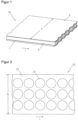
- Figure 1 illustrates the structure of a coated carrier film web 10 for the production of transdermal therapeutic systems. To better illustrate the facts, the illustration is not to scale.
- the coated carrier film web 10, of which Figure 1 only a portion is shown, has a certain width b and a length l that is significantly greater in relation to the width.
- the coated carrier film web 10 consists of at least two layers, the carrier film web 1 and an active substance-containing coating 2 applied thereto. Usually, the side of the active substance-containing coating 2 facing away from the carrier film web 1, as in Figure 1 illustrated example, additionally by a covered by a cover film 3.
- the active substance-containing coating 2 extends over the entire width b of the carrier film web, as shown in Figure 1 shown only over a part of its width, or is applied to the carrier film 1 in the form of several individual webs arranged next to one another. For the purposes of an improved use of the active substance-containing coating 2 as described below, this extends over the entire width b of the carrier film web 1 or at least almost over the entire width b of the carrier film web 1.
- the active substance-containing coating 2 can be constructed in one layer or in several layers and can also comprise a membrane.
- the width of the coated carrier film web 10 depends not only on the particular transdermal therapeutic system to be produced, but also primarily on the characteristics of the apparatus used for production.
- the web widths used are usually several times the widths of the transdermal therapeutic systems to be produced from them.
- the active substance depots 12 in the active substance-containing coating 2 are therefore usually separated in an arrangement comprising several rows.
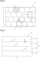
- Such a matrix-shaped arrangement of active substance depots 12 is in Figure 2
- the individual active substance depots 12, of which only one is provided with a reference symbol in the figure to represent all, are arranged in three rows in the arrangement shown.
- the rows extending in the longitudinal direction of the coated carrier film web 10 are arranged next to one another with respect to the width of the film web 10.
- the active substance depots of different rows adjacent to one another are not offset from one another in the longitudinal direction of the carrier film web 10, but are essentially located at the same longitudinal position of the coated carrier film web 10.
- the arrangement of the active ingredient depots 12 corresponds to a field arrangement structured in rows and columns, which is a prerequisite for the batch-wise transfer of all active ingredient depots 12 located at the same length position of the film web 10 to a protective film or for the batch-wise separation of the film web into individual sections as part of a separation of the individual transdermal therapeutic systems.
- Batch-wise treatment of the active ingredient depots is understood here to mean simultaneous treatment of active ingredient depots located next to one another in a column of the field arrangement.
- the active substance depots 12 are spaced apart from one another both in the longitudinal direction of the coated carrier film web 10 and transversely thereto, so that a continuous grid 13 is obtained which can be easily peeled off the carrier film.
- An arrangement with improved utilization of the active substance-containing coating 2 is described in Figure 8 shown.
- the round active substance depots 12 of adjacent rows are arranged offset from one another with respect to the longitudinal direction l of the coated carrier film web 10, with the rows engaging with one another in such a way that the space available between two adjacent active substance depots 12 of a row is also used by an active substance depot 12 of a row arranged immediately adjacent to this row.
- the distance between active substance depots 12 arranged transversely to the longitudinal extent of the carrier film 10, referred to below as row spacing ⁇ s is smaller with the same grid width than with an arrangement according to Figure 2 .
- the longitudinal offset ⁇ l between active ingredient depots 12 of adjacent rows hinders further processing in columns in batches as described above.
- the coated carrier film web 10 is divided into several partial webs, each of the partial webs containing a row of areas intended for active ingredient depots 12.
- the relative position of the partial webs to one another is then changed so that the areas intended for active ingredient depots 12 of different partial webs are arranged next to one another in the transverse direction without longitudinal offset ⁇ l and without interference ⁇ u (see Figure 4 ) are arranged.
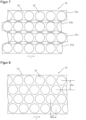
- the active substance-containing coating 2 of width b is subdivided into several, preferably congruent cell areas 11.
- One of the cell areas is in Figure 3 provided with a reference symbol to represent all and shown hatched for better recognition of its geometry.
- the individual cell areas 11 are directly adjacent to one another without intermediate areas and do not overlap.
- the size and shape of a cell area 11 depend on the size and shape of the active ingredient depots 12 to be produced and the space required for removing the punched grid or for a projection of the later part of the release liner, which represents the carrier of the individual active ingredient depots.
- Figure 3 The cell areas 11 shown are designed for circular active substance depots 12, the intended position of which in three of the cell areas 11 is indicated by dashed lines. The determination of the shape and arrangement of the cell areas is preferably carried out with regard to a under given conditions, the areas intended for the formation of the active substance depots on the active substance-containing coating 2 are arranged as densely as possible.
- Figure 3 In the example shown, the cell area shape has been developed for optimal use of the active substance-containing coating 2 while maintaining a minimum distance d (grid web width) between active substance areas 12 that are immediately adjacent to one another.
- active substance depots 12 When producing other forms of active substance depots 12, cell areas with border geometries naturally result, which differ from the Figure 3 shown.
- the active substance-containing coating 2 can be subdivided into an arrangement of different sizes and also differently shaped cell regions 11.
- a space-utilizing shape and arrangement of cell areas 11 can be characterized in such a way that, as in Figure 3 illustrated, the sum of the individual transverse dimensions Q of two cell regions 11 arranged next to one another in the transverse direction of the carrier film 10 is greater than the total transverse dimension gQ of these two cell regions.
- the described determination of an arrangement of non-overlapping cell areas 11 on the active substance-containing coating 2 is purely organizational in nature and is usually not reflected in an actual marking or structuring of the active substance-containing Coating 2. However, it is the basis for, or results indirectly from, the arrangement of the dividing lines along which the coated carrier film web 10 is separated into several partial webs.
- the first step of the method described is therefore an organizational step that is reflected in the manufacturing steps described below, which change the physical design of the coated carrier film web 10, but does not itself constitute such a manufacturing step.
- Figure 4 shows an embodiment of an arrangement of separating lines 14 for separating the coated carrier film web 10 into four partial webs 15a, 15b, 15c and 15d, each of which has exactly one row of Figure 3 shown cell areas 11.
- the dividing lines are the active substance depot or cell area arrangement of Figure 3 correspondingly wave-shaped, with the distance ⁇ u between two consecutive turning points of the wave lines indicating the engagement of two partial webs 15 interlocking at the respective wave line.
- the separation of the carrier film web 10 along the separation lines 14, which forms the second step of the method described above, is carried out using a cutting or punching device (not shown in the figures).
- the separation can be carried out discontinuously with, for example, a contour punch or continuously with, for example, a contour cutting roller.
- This ensures that the individual partial webs do not overlap in the In the subsequent step, the individual partial webs can at best touch at certain points to compensate for the longitudinal offset ⁇ l, but cannot partially cover each other.
- every second of the partial webs can also be transferred to a different plane.
- every second of the partial webs is offset or shifted relative to the others by a distance corresponding to the longitudinal offset ⁇ l.
- a four-row arrangement as in Figure 6 illustrates the edge partial web 15a and the partial web 15c next to it being displaced relative to the other two partial webs 15b and 15d by a distance corresponding to the longitudinal offset ⁇ l in the longitudinal direction l of the carrier film web 10.
- the displacement can be realized in a production plant, for example, by running the partial webs over different lengths.
- the individual partial webs of the active ingredient-containing coating 2 can be laminated onto a new carrier film, preferably onto a protective film.
- Each of the protective films assigned to a partial web can be made up of several parts, which means that it is made up of several partial webs, at least two of which are adjacent to one another or overlap so that they form a closed surface.
- the dividing line between the two protective film parts or their overlapping area is preferably arranged so that it is covered by the areas intended for the formation of the active ingredient depots 12.
- the active substance deposits 12 are separated in the active substance-containing coating partial webs. This is done by cutting through the active substance-containing coating 2 along closed linear geometries, each of these geometries being arranged in a region of the coating 2 assigned to a cell region 11. Since the active substance depots 12 have certain contours or formats, this step is also referred to as contour or format punching.
- the grids 13 are removed from the partial coating webs in a process generally referred to as stripping. If a one-piece protective film was used in the previous lamination of the partial coating webs, this is converted into a multi-piece protective film by cutting lengthwise after stripping, whereby the protective film is thereby separated into several partial webs, each carrying a row of active ingredient depots, and each of these partial webs can be provided with a separating cut or perforation running under the active ingredient depots 12. In a subsequent processing step, the protective film webs are severed in the transverse direction in the areas between the active ingredient depots to obtain individual systems. Further optional processing steps can optionally include covering the active ingredient depots 12 with an active ingredient-impermeable cover or backing film and packaging the individual systems.
- the method described above can also be carried out in a sequence of process steps to improve the use of the active ingredient-containing coating, in which after the (at least The step of dividing the carrier film 10 into individual cell areas 11, which is carried out (in theory), is first of all the format punching for separating the active substance depots 12, as is the case, for example, in Figure 8
- the grid 13 can then be removed from the carrier film 1, whereupon the Figure 9 illustrated separation of the carrier film 10 takes place along the separation lines 14 determined by the cell area arrangement.
- the individual partial webs are spaced laterally (ie transversely to the longitudinal direction l of the carrier film web 10) and the longitudinal offset between immediately adjacent partial webs is compensated, so that, for example, an arrangement of the format-punched partial webs 15a, 15b, 15c and 15d according to the schematic representation of Figure 10
- the punched coating strips are laminated onto a protective film after the longitudinal offset has been compensated, before this is separated by longitudinal cutting or longitudinal punching into the possibly multi-part strips described above.
- the protective film strips are also cut crosswise to separate the systems as described above.
- the partial webs are first shifted relative to one another as in the first embodiment explained above in order to eliminate the engagement ⁇ u and the length offset ⁇ l, before the coating partial webs created in this way are each transferred to a protective film web that may be made up of several parts.
- the active ingredient depots are then formed by contour punching of the laminated coating partial webs, and the parts of the coating partial webs that are not used as active ingredient depots are screened off before the systems are separated by cross-cutting the protective film webs.
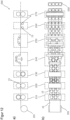
- step S1 A clear representation of the individual steps of a method 100 for better use of the active substance-containing coating 2 according to the second-mentioned process sequence is shown in the flow chart of the Figure 11
- the method 100 begins in step S1 with the subdivision of the carrier film 10 into individual cell regions 11, each of which is assigned to an individual active ingredient depot format 12. It should be pointed out again that this step is purely conceptual in nature and does not involve or have to involve any physical change to the coated carrier film 10.
- step S2 the format punching takes place to form the individual active ingredient depots 12 in the coating layer 2 or, if applicable, in the coating layer 2 provided with a cover film 3.
- step S3 the part 13 of the active ingredient-containing coating layer 2, possibly coated with a cover film 3, that is not used for active ingredient depots 12 is screened off.
- step S4 the carrier film 10 carrying the active ingredient depots 12 is separated along the dividing lines 14 into individual partial webs, for example into partial webs 15a, 15b, 15c and 15d.
- step S5 the engagement of the partial webs is removed and then or simultaneously in step S6 the longitudinal offset between the partial webs is compensated, after which cell areas 11 arranged next to one another transversely to the longitudinal direction of the partial webs are arranged at the same height, i.e. without longitudinal offset to one another.
- step S7 The removal of the engagement ⁇ u or the engagement of the partial webs in one another can be achieved by increasing the distance between the partial webs transversely to the longitudinal extent of the partial webs and by transferring every second partial web to a different plane.
- the active substance depots are later laminated onto separate protective film webs (step S7).
- the removal of the longitudinal offset between the partial webs carrying active substance depots can be achieved by guiding adjacent partial webs over sections of different lengths.
- step S7 the active substance depots 12 of the individual Partial webs are laminated onto one or more protective film webs or one or more other carrier film webs.
- the protective films which may be made up of multiple parts, are cut crosswise to separate the systems, and in step S9 the systems are sent for further processing.
- the method 100 can be carried out in the described sequence of method steps as well as in a sensible sequence of method steps as described above or otherwise deviating therefrom.
- the steps S7 and S8 shown in the process sequence can be omitted.
- the partial webs can be cut directly by cross-cutting after step S6 without the Figure 11
- the desired product can be obtained for further processing in the intermediate step S7 shown. Accordingly, the process steps after step S6 can be freely selected by the person skilled in the art according to the respective requirements and objectives.
- the described manufacturing process enables improved use of a coating containing active substances applied to a carrier film for the production of transdermal therapeutic systems, whereby the device components required to implement the process can be integrated into existing systems for the production of transdermal or comparable systems for transdermal or permucosal drug administration.
- the described manufacturing process can also be easily adapted, for example, for the production of orodispersible tablets (ODT), which are usually round in shape.
- Illustration a shows the devices in a side view and illustration b) in a top view.
- the arrangement of the devices shown relative to each other is in relation to the Figure 11
- the illustrated procedure has been chosen and can vary accordingly if the procedure is chosen differently.
- the devices described below are highlighted in the figure with a dashed frame for better recognition.
- the device 200 of the disclosure comprises a contouring device 210 for separating active substance depots 12 in the coating layer 2, optionally provided with a cover layer 3, by means of format or contour punching, a grating device 220 for removing the part of the coating layer 2, optionally provided with a cover layer 3, which is usually referred to as a grating and is not used as an active substance depot 12 from the carrier film web 1 and a separating device 230 for longitudinally separating the carrier film web 1 into two or more partial webs 15.
- the displacement device 240 can comprise pivoting frames as illustrated, which guide the individual partial webs 15 laterally, ie transversely to their longitudinal or transport direction, a corresponding distance apart.
- a transfer device 240 guide adjacent partial webs 15 over different rollers, which are arranged in such a way that adjacent partial webs 15 are guided to different levels.
- adjacent partial webs 15 are guided over sections of different lengths, the differences in the sections essentially corresponding to the original longitudinal offset ⁇ l of the active substance depots 12 of adjacent partial webs 15.
- the active substance depots 12 are laminated onto a protective film, possibly made up of several parts, as described above.
- the laminating device 260 is designed to feed a number of protective films, possibly consisting of multiple parts, corresponding to the partial webs 15 to the partial webs guided in different planes.
- the device 200 of the disclosure finally has a cross-cutting device 270, which is designed to sever the protective film, possibly previously divided into several webs using a longitudinal cutting device (not shown), transversely to the longitudinal direction in the areas between the active substance depots 12.
- the coated carrier film web 10 is preferably fed to the described devices via a winding roll 201.
- the contouring device 210 is or comprises a punching device with punching blades, which in some cases are firmly (ie unchangeably) connected to the punching device.
- the punching blades of the punching device are mounted in such a way that during format punching in step S2 an arrangement of the active substance depots 12 as described above with optimized use of space results.
- the punching blades can thus be mounted in particular in such a way that the Figure 8
- the arrangement of active substance depots 12 shown has a predetermined row spacing ⁇ s as well as a predetermined longitudinal offset ⁇ l, each of which is greater than zero.
- the row spacing ⁇ s and the longitudinal offset ⁇ l are selected such that the use of the active substance-containing coating is Figure 2
- the improvement is therefore achieved by reducing the proportion of the area of the active substance-containing coating not used by the active substance depots, ie by reducing the lattice loss.
- the contouring device 210 is or comprises a punching roller with fixedly attached punching blades, wherein the punching blades are arranged such that the grid loss is reduced.
- the punching blades are typically arranged such that the arrangement of active substance depots (12) formed by the format punching in step (S2) has a predetermined row spacing ⁇ s and a predetermined longitudinal offset ⁇ l, each of which is greater than zero and each of which is selected such that the grid loss is reduced.
- the punching blades of the punching device can be arranged such that, when the punching device is used during format punching in step (S2), preferably round or oval active substance depots (12) arranged in rows are formed, wherein the rows engage with one another such that the space available between two adjacent active substance depots 12 of a row is also used by an active substance depot 12 of a row arranged immediately adjacent to this row.
Landscapes
- Health & Medical Sciences (AREA)
- Engineering & Computer Science (AREA)
- Bioinformatics & Cheminformatics (AREA)
- Dermatology (AREA)
- Chemical & Material Sciences (AREA)
- Medicinal Chemistry (AREA)
- Pharmacology & Pharmacy (AREA)
- Epidemiology (AREA)
- Life Sciences & Earth Sciences (AREA)
- Animal Behavior & Ethology (AREA)
- General Health & Medical Sciences (AREA)
- Public Health (AREA)
- Veterinary Medicine (AREA)
- Mechanical Engineering (AREA)
- Medicinal Preparation (AREA)
- Acyclic And Carbocyclic Compounds In Medicinal Compositions (AREA)
Priority Applications (6)
| Application Number | Priority Date | Filing Date | Title |
|---|---|---|---|
| EP13700903.1A EP2804734B2 (de) | 2012-01-20 | 2013-01-21 | Gitterverlustreduktion bei pflasterherstellung |
| SI201330200A SI2804734T1 (sl) | 2012-01-20 | 2013-01-21 | Zmanjšana izguba mrežnega materiala pri izdelavi obliža |
| RS20160465A RS54864B1 (sr) | 2012-01-20 | 2013-01-21 | Redukcija gubitka materijala rešetke tokom proizvodnje flastera |
| HRP20160614TT HRP20160614T1 (hr) | 2012-01-20 | 2013-01-21 | Smanjeni gubitak materijala rešetke u proizvodnji flastera |
| CY20161100567T CY1117679T1 (el) | 2012-01-20 | 2016-06-24 | Περιορισμος απωλειας πλεγματος κατα την παραγωγη εμπλαστρων |
| SM201600200T SMT201600200B (it) | 2012-01-20 | 2016-06-24 | Perdita ridotta di griglia nella produzione di cerotti |
Applications Claiming Priority (3)
| Application Number | Priority Date | Filing Date | Title |
|---|---|---|---|
| EP12152009 | 2012-01-20 | ||
| EP13700903.1A EP2804734B2 (de) | 2012-01-20 | 2013-01-21 | Gitterverlustreduktion bei pflasterherstellung |
| PCT/EP2013/051058 WO2013107909A1 (de) | 2012-01-20 | 2013-01-21 | Gitterverlustreduktion |
Publications (3)
| Publication Number | Publication Date |
|---|---|
| EP2804734A1 EP2804734A1 (de) | 2014-11-26 |
| EP2804734B1 EP2804734B1 (de) | 2016-04-13 |
| EP2804734B2 true EP2804734B2 (de) | 2025-01-15 |
Family
ID=47598837
Family Applications (1)
| Application Number | Title | Priority Date | Filing Date |
|---|---|---|---|
| EP13700903.1A Active EP2804734B2 (de) | 2012-01-20 | 2013-01-21 | Gitterverlustreduktion bei pflasterherstellung |
Country Status (14)
| Country | Link |
|---|---|
| US (1) | US10758495B2 (sr) |
| EP (1) | EP2804734B2 (sr) |
| KR (1) | KR102009061B1 (sr) |
| CY (1) | CY1117679T1 (sr) |
| DK (1) | DK2804734T3 (sr) |
| ES (1) | ES2577886T5 (sr) |
| HR (1) | HRP20160614T1 (sr) |
| HU (1) | HUE027744T2 (sr) |
| PL (1) | PL2804734T5 (sr) |
| PT (1) | PT2804734T (sr) |
| RS (1) | RS54864B1 (sr) |
| SI (1) | SI2804734T1 (sr) |
| SM (1) | SMT201600200B (sr) |
| WO (1) | WO2013107909A1 (sr) |
Citations (6)
| Publication number | Priority date | Publication date | Assignee | Title |
|---|---|---|---|---|
| US4164170A (en) † | 1977-02-17 | 1979-08-14 | Rimbo Tekniska Fabrik Rimpac Ab | Method of making bags |
| DE3432331A1 (de) † | 1984-09-03 | 1986-03-13 | Hassia Verpackungsmaschinen GmbH, 6479 Ranstadt | Verpackungsmaschine fuer in huellpackungen einzubringende, doppelfolig verklebte medikamentenpflaster |
| US4681001A (en) † | 1985-07-01 | 1987-07-21 | Km-Engineering Ag | Method of making scroll strip blanks |
| EP0848937A2 (en) † | 1996-12-21 | 1998-06-24 | Sunkyong Industries Co. | Apparatus for manufacturing medicinal pathes for percutaneous administration |
| DE19837764C1 (de) † | 1998-08-20 | 2000-03-16 | Lohmann Therapie Syst Lts | Verfahren zum Herstellen von klebenden Stanzlingen aus einer endlosen Bahn und nach dem Verfahren hergestellter Stanzling |
| DE19946384A1 (de) † | 1999-09-28 | 2001-04-05 | Lohmann Therapie Syst Lts | Verfahren und Vorrichtung zum Spenden haftklebender Laminatabschnitte von einer beweglichen primären auf eine bewegliche sekundäre Trägerbahn |
Family Cites Families (20)
| Publication number | Priority date | Publication date | Assignee | Title |
|---|---|---|---|---|
| US1433138A (en) * | 1921-02-26 | 1922-10-24 | Bliss E W Co | Zigzag cutter |
| US1826889A (en) * | 1926-12-31 | 1931-10-13 | Henry C Koch | Cutter head |
| US2530319A (en) * | 1945-11-16 | 1950-11-14 | Irvin L Young | Paper-cutting machine |
| US3517532A (en) * | 1965-09-27 | 1970-06-30 | Bendix Corp | Apparatus for slitting sheet metal and method of forming circular members therefrom |
| US3762250A (en) * | 1971-06-16 | 1973-10-02 | Du Pont | Method of and apparatus for handling material |
| DE3004220C2 (de) * | 1980-02-06 | 1985-04-04 | Hans 5216 Niederkassel Lehmacher | Vorrichtung für die Herstellung von Kunststofftaschen |
| DE3004244C2 (de) * | 1980-02-06 | 1983-12-15 | Hans 5216 Niederkassel Lehmacher | Vorrichtung für die Herstellung von Kunststofftaschen |
| DE3336231A1 (de) * | 1983-10-05 | 1985-04-25 | Windmöller & Hölscher, 4540 Lengerich | Vorrichtung zum herstellen von kunststofftragetaschen |
| US4846033A (en) * | 1985-07-01 | 1989-07-11 | Km-Engineering Ag | Apparatus for making blanks and strips of blanks |
| DE3728888A1 (de) * | 1987-08-29 | 1989-03-09 | Bentz & Sohn Melitta | Verfahren zur herstellung von zuschnitten aus einem elastischen papier, vorzugsweise einem gekreppten papier, sowie vorrichtung zur durchfuehrung des verfahrens |
| US5405486A (en) * | 1988-03-04 | 1995-04-11 | Noven Pharmaceuticals, Inc. | Apparatus for forming a transdermal drug device |
| US6126507A (en) | 1997-03-13 | 2000-10-03 | Chameleon Products, Inc. | Reversible doll/hat |
| US6336307B1 (en) * | 1997-10-09 | 2002-01-08 | Eki Holding Corporation | Method of packaging a strip of material for use in cutting into sheet elements arranged end to end |
| US6183770B1 (en) | 1999-04-15 | 2001-02-06 | Acutek International | Carrier patch for the delivery of agents to the skin |
| US6994005B2 (en) * | 2002-03-01 | 2006-02-07 | Energy Saving Products And Sales Corp. | Apparatus for slitting, merging, and cutting a continuous paperweb |
| US8608889B2 (en) * | 2005-06-10 | 2013-12-17 | 3M Innovative Properties Company | Method for handling adhesive laminate sections |
| US7331266B2 (en) * | 2005-11-14 | 2008-02-19 | Sdi Corporation | Paper punch with two articulated linkages |
| DE502008001671D1 (de) | 2007-08-21 | 2010-12-09 | Lohmann Therapie Syst Lts | Verfahren zum mehrspurigen konfektionieren transdermaler therapeutischer pflaster |
| DE102008059054A1 (de) | 2008-11-26 | 2010-05-27 | Otto Bock Pur Life Science Gmbh | Polyurethanpflaster für die transdermale Applikation von Wirkstoffen und Verfahren zu dessen Herstellung |
| FR2950044B1 (fr) | 2009-09-11 | 2011-12-09 | Commissariat Energie Atomique | Procede de preparation d'une surface structuree fonctionnelle et surface obtenue par le procede |
-
2013
- 2013-01-21 RS RS20160465A patent/RS54864B1/sr unknown
- 2013-01-21 SI SI201330200A patent/SI2804734T1/sl unknown
- 2013-01-21 EP EP13700903.1A patent/EP2804734B2/de active Active
- 2013-01-21 DK DK13700903.1T patent/DK2804734T3/en active
- 2013-01-21 PT PT137009031T patent/PT2804734T/pt unknown
- 2013-01-21 US US14/372,268 patent/US10758495B2/en active Active
- 2013-01-21 HU HUE13700903A patent/HUE027744T2/en unknown
- 2013-01-21 ES ES13700903T patent/ES2577886T5/es active Active
- 2013-01-21 WO PCT/EP2013/051058 patent/WO2013107909A1/de not_active Ceased
- 2013-01-21 PL PL13700903.1T patent/PL2804734T5/pl unknown
- 2013-01-21 HR HRP20160614TT patent/HRP20160614T1/hr unknown
- 2013-01-21 KR KR1020147018482A patent/KR102009061B1/ko active Active
-
2016
- 2016-06-24 SM SM201600200T patent/SMT201600200B/it unknown
- 2016-06-24 CY CY20161100567T patent/CY1117679T1/el unknown
Patent Citations (6)
| Publication number | Priority date | Publication date | Assignee | Title |
|---|---|---|---|---|
| US4164170A (en) † | 1977-02-17 | 1979-08-14 | Rimbo Tekniska Fabrik Rimpac Ab | Method of making bags |
| DE3432331A1 (de) † | 1984-09-03 | 1986-03-13 | Hassia Verpackungsmaschinen GmbH, 6479 Ranstadt | Verpackungsmaschine fuer in huellpackungen einzubringende, doppelfolig verklebte medikamentenpflaster |
| US4681001A (en) † | 1985-07-01 | 1987-07-21 | Km-Engineering Ag | Method of making scroll strip blanks |
| EP0848937A2 (en) † | 1996-12-21 | 1998-06-24 | Sunkyong Industries Co. | Apparatus for manufacturing medicinal pathes for percutaneous administration |
| DE19837764C1 (de) † | 1998-08-20 | 2000-03-16 | Lohmann Therapie Syst Lts | Verfahren zum Herstellen von klebenden Stanzlingen aus einer endlosen Bahn und nach dem Verfahren hergestellter Stanzling |
| DE19946384A1 (de) † | 1999-09-28 | 2001-04-05 | Lohmann Therapie Syst Lts | Verfahren und Vorrichtung zum Spenden haftklebender Laminatabschnitte von einer beweglichen primären auf eine bewegliche sekundäre Trägerbahn |
Also Published As
| Publication number | Publication date |
|---|---|
| ES2577886T5 (en) | 2025-06-02 |
| DK2804734T3 (en) | 2016-07-04 |
| ES2577886T3 (es) | 2016-07-19 |
| HUE027744T2 (en) | 2016-10-28 |
| US10758495B2 (en) | 2020-09-01 |
| WO2013107909A1 (de) | 2013-07-25 |
| KR20140117383A (ko) | 2014-10-07 |
| PT2804734T (pt) | 2016-07-07 |
| PL2804734T3 (pl) | 2016-09-30 |
| US20140364294A1 (en) | 2014-12-11 |
| HRP20160614T1 (hr) | 2016-07-01 |
| RS54864B1 (sr) | 2016-10-31 |
| EP2804734A1 (de) | 2014-11-26 |
| SMT201600200B (it) | 2016-08-31 |
| PL2804734T5 (pl) | 2025-05-05 |
| CY1117679T1 (el) | 2017-05-17 |
| KR102009061B1 (ko) | 2019-08-08 |
| SI2804734T1 (sl) | 2016-07-29 |
| EP2804734B1 (de) | 2016-04-13 |
Similar Documents
| Publication | Publication Date | Title |
|---|---|---|
| DE19837764C1 (de) | Verfahren zum Herstellen von klebenden Stanzlingen aus einer endlosen Bahn und nach dem Verfahren hergestellter Stanzling | |
| EP0943138B1 (de) | Flächiges selbsthaftendes wirkstoffpflaster | |
| DE102011010601A1 (de) | Verpackungsmaschine zum Herstellen einer Mehrlagenpackung | |
| EP2851168B1 (de) | Vorrichtung zum Ausstanzen von Etiketten mit Gegenstanzband | |
| DE2000833A1 (de) | Zusammenhaengender Verband mit Briefumschlaegen | |
| WO2001022946A2 (de) | Verfahren und vorrichtung zum spenden haftklebender laminatabschnitte | |
| DE29622554U1 (de) | Teilbare Verpackung, insbesondere Zigarettenkartusche | |
| EP2804734B2 (de) | Gitterverlustreduktion bei pflasterherstellung | |
| EP3181311B1 (de) | Vorrichtung zum herauslösen von teilbereichen aus einer materialbahn | |
| EP3626793A1 (de) | Klebeband mit geformter abziehlasche und verfahren zur herstellung eines solchen klebebandes | |
| DE2755648C2 (de) | Vorrichtung zum Durchtrennen einer Bahn aus Papier | |
| EP3030388B1 (de) | Transfer-stanzen | |
| DE102009010045A1 (de) | Verfahren zur Herstellung von Klebestreifen | |
| EP1985550A1 (de) | Verpackungseinheit für Arzneimittel und Verfahren zu deren Herstellung | |
| EP3275820B1 (de) | Vorrichtung zum schneiden einer materialbahn in teilabschnitte | |
| EP2411230B1 (de) | Als zeitung ausgebildetes druckprodukt | |
| DE102019114489A1 (de) | Verfahren zum rotativen Stanzen von Folienmaterialien | |
| DE3937024A1 (de) | Vorrichtung zur herstellung von einlagen fuer versandhuellen | |
| DE2440963C3 (sr) | ||
| DE102005041226B4 (de) | Etikettenband | |
| DE1223244B (de) | Selbstklebeetikett | |
| EP4491358A1 (de) | Vorrichtung und verfahren zum einbringen von fensterausschnitten in ein bahnförmiges rahmenmaterial | |
| DE1546904A1 (de) | Mehrschichtiges Band | |
| EP3702427A1 (de) | Beidseitig mit klebstoff beschichtete folien | |
| DE9311792U1 (de) | Einrichtung zum Perforieren von Substraten |
Legal Events
| Date | Code | Title | Description |
|---|---|---|---|
| PUAI | Public reference made under article 153(3) epc to a published international application that has entered the european phase |
Free format text: ORIGINAL CODE: 0009012 |
|
| 17P | Request for examination filed |
Effective date: 20140403 |
|
| AK | Designated contracting states |
Kind code of ref document: A1 Designated state(s): AL AT BE BG CH CY CZ DE DK EE ES FI FR GB GR HR HU IE IS IT LI LT LU LV MC MK MT NL NO PL PT RO RS SE SI SK SM TR |
|
| RIN1 | Information on inventor provided before grant (corrected) |
Inventor name: PIOTROWSKI, HOLGER Inventor name: GRADER, LUDWIG |
|
| DAX | Request for extension of the european patent (deleted) | ||
| GRAP | Despatch of communication of intention to grant a patent |
Free format text: ORIGINAL CODE: EPIDOSNIGR1 |
|
| INTG | Intention to grant announced |
Effective date: 20150929 |
|
| GRAS | Grant fee paid |
Free format text: ORIGINAL CODE: EPIDOSNIGR3 |
|
| GRAA | (expected) grant |
Free format text: ORIGINAL CODE: 0009210 |
|
| AK | Designated contracting states |
Kind code of ref document: B1 Designated state(s): AL AT BE BG CH CY CZ DE DK EE ES FI FR GB GR HR HU IE IS IT LI LT LU LV MC MK MT NL NO PL PT RO RS SE SI SK SM TR |
|
| REG | Reference to a national code |
Ref country code: GB Ref legal event code: FG4D Free format text: NOT ENGLISH |
|
| REG | Reference to a national code |
Ref country code: AT Ref legal event code: REF Ref document number: 789621 Country of ref document: AT Kind code of ref document: T Effective date: 20160415 Ref country code: CH Ref legal event code: EP |
|
| REG | Reference to a national code |
Ref country code: IE Ref legal event code: FG4D Free format text: LANGUAGE OF EP DOCUMENT: GERMAN |
|
| REG | Reference to a national code |
Ref country code: DE Ref legal event code: R096 Ref document number: 502013002560 Country of ref document: DE |
|
| REG | Reference to a national code |
Ref country code: HR Ref legal event code: TUEP Ref document number: P20160614 Country of ref document: HR |
|
| REG | Reference to a national code |
Ref country code: RO Ref legal event code: EPE |
|
| REG | Reference to a national code |
Ref country code: HR Ref legal event code: T1PR Ref document number: P20160614 Country of ref document: HR |
|
| REG | Reference to a national code |
Ref country code: DK Ref legal event code: T3 Effective date: 20160627 |
|
| REG | Reference to a national code |
Ref country code: PT Ref legal event code: SC4A Ref document number: 2804734 Country of ref document: PT Date of ref document: 20160707 Kind code of ref document: T Free format text: AVAILABILITY OF NATIONAL TRANSLATION Effective date: 20160621 |
|
| REG | Reference to a national code |
Ref country code: NL Ref legal event code: FP |
|
| REG | Reference to a national code |
Ref country code: SE Ref legal event code: TRGR Ref country code: ES Ref legal event code: FG2A Ref document number: 2577886 Country of ref document: ES Kind code of ref document: T3 Effective date: 20160719 |
|
| REG | Reference to a national code |
Ref country code: NO Ref legal event code: T2 Effective date: 20160413 |
|
| REG | Reference to a national code |
Ref country code: EE Ref legal event code: FG4A Ref document number: E012036 Country of ref document: EE Effective date: 20160617 |
|
| REG | Reference to a national code |
Ref country code: GR Ref legal event code: EP Ref document number: 20160401369 Country of ref document: GR Effective date: 20160729 |
|
| REG | Reference to a national code |
Ref country code: HU Ref legal event code: AG4A Ref document number: E027744 Country of ref document: HU |
|
| REG | Reference to a national code |
Ref country code: SK Ref legal event code: T3 Ref document number: E 21363 Country of ref document: SK |
|
| REG | Reference to a national code |
Ref country code: DE Ref legal event code: R026 Ref document number: 502013002560 Country of ref document: DE |
|
| PLBI | Opposition filed |
Free format text: ORIGINAL CODE: 0009260 |
|
| REG | Reference to a national code |
Ref country code: FR Ref legal event code: PLFP Year of fee payment: 5 |
|
| PLAX | Notice of opposition and request to file observation + time limit sent |
Free format text: ORIGINAL CODE: EPIDOSNOBS2 |
|
| 26 | Opposition filed |
Opponent name: LTS LOHMANN THERAPIE SYSTEM GMBH Effective date: 20170113 |
|
| REG | Reference to a national code |
Ref country code: DE Ref legal event code: R082 Ref document number: 502013002560 Country of ref document: DE Representative=s name: LEDERER & KELLER PATENTANWAELTE PARTNERSCHAFT , DE Ref country code: DE Ref legal event code: R081 Ref document number: 502013002560 Country of ref document: DE Owner name: LUYE PHARMA AG, DE Free format text: FORMER OWNER: ACINO AG, 83714 MIESBACH, DE |
|
| REG | Reference to a national code |
Ref country code: CH Ref legal event code: PFA Owner name: LUYE PHARMA AG, DE Free format text: FORMER OWNER: ACINO AG, DE |
|
| REG | Reference to a national code |
Ref country code: NO Ref legal event code: CHAD Owner name: LUVE PHARMA AG, DE |
|
| REG | Reference to a national code |
Ref country code: NL Ref legal event code: HC Owner name: LUYE PHARMA AG; DE Free format text: DETAILS ASSIGNMENT: CHANGE OF OWNER(S), CHANGE OF OWNER(S) NAME; FORMER OWNER NAME: ACINO AG Effective date: 20170314 |
|
| RAP2 | Party data changed (patent owner data changed or rights of a patent transferred) |
Owner name: LUYE PHARMA AG |
|
| REG | Reference to a national code |
Ref country code: HU Ref legal event code: HC9C Owner name: LUYE PHARMA AG, DE Free format text: FORMER OWNER(S): ACINO AG, DE |
|
| REG | Reference to a national code |
Ref country code: EE Ref legal event code: HC1A Ref document number: E012036 Country of ref document: EE |
|
| REG | Reference to a national code |
Ref country code: LU Ref legal event code: HC Owner name: LUYE PHARMA AG; DE Free format text: FORMER OWNER: ACINO AG Effective date: 20170329 |
|
| PLBB | Reply of patent proprietor to notice(s) of opposition received |
Free format text: ORIGINAL CODE: EPIDOSNOBS3 |
|
| REG | Reference to a national code |
Ref country code: SK Ref legal event code: TC4A Ref document number: E 21363 Country of ref document: SK Owner name: LUYE PHARMA AG, MIESBACH, DE Effective date: 20170824 |
|
| REG | Reference to a national code |
Ref country code: HR Ref legal event code: PNAN Ref document number: P20160614 Country of ref document: HR Owner name: LUYE PHARMA AG, DE |
|
| REG | Reference to a national code |
Ref country code: FR Ref legal event code: TP Owner name: LUYE PHARMA AG, DE Effective date: 20171114 |
|
| REG | Reference to a national code |
Ref country code: FR Ref legal event code: PLFP Year of fee payment: 6 |
|
| REG | Reference to a national code |
Ref country code: AT Ref legal event code: HC Ref document number: 789621 Country of ref document: AT Kind code of ref document: T Owner name: LUYE PHARMA AG, DE Effective date: 20180206 |
|
| PLCK | Communication despatched that opposition was rejected |
Free format text: ORIGINAL CODE: EPIDOSNREJ1 |
|
| STAA | Information on the status of an ep patent application or granted ep patent |
Free format text: STATUS: THE PATENT HAS BEEN GRANTED |
|
| APBM | Appeal reference recorded |
Free format text: ORIGINAL CODE: EPIDOSNREFNO |
|
| APBP | Date of receipt of notice of appeal recorded |
Free format text: ORIGINAL CODE: EPIDOSNNOA2O |
|
| APAH | Appeal reference modified |
Free format text: ORIGINAL CODE: EPIDOSCREFNO |
|
| APBQ | Date of receipt of statement of grounds of appeal recorded |
Free format text: ORIGINAL CODE: EPIDOSNNOA3O |
|
| REG | Reference to a national code |
Ref country code: HR Ref legal event code: ODRP Ref document number: P20160614 Country of ref document: HR Payment date: 20190110 Year of fee payment: 7 |
|
| REG | Reference to a national code |
Ref country code: HR Ref legal event code: ODRP Ref document number: P20160614 Country of ref document: HR Payment date: 20200109 Year of fee payment: 8 |
|
| PGFP | Annual fee paid to national office [announced via postgrant information from national office to epo] |
Ref country code: DK Payment date: 20200123 Year of fee payment: 8 Ref country code: RO Payment date: 20200113 Year of fee payment: 8 Ref country code: LT Payment date: 20200107 Year of fee payment: 8 Ref country code: MC Payment date: 20200122 Year of fee payment: 8 Ref country code: FI Payment date: 20200121 Year of fee payment: 8 Ref country code: NO Payment date: 20200123 Year of fee payment: 8 Ref country code: PT Payment date: 20200110 Year of fee payment: 8 Ref country code: HU Payment date: 20200108 Year of fee payment: 8 Ref country code: BG Payment date: 20200127 Year of fee payment: 8 Ref country code: AT Payment date: 20200121 Year of fee payment: 8 Ref country code: EE Payment date: 20200122 Year of fee payment: 8 Ref country code: LV Payment date: 20200124 Year of fee payment: 8 |
|
| PGFP | Annual fee paid to national office [announced via postgrant information from national office to epo] |
Ref country code: RS Payment date: 20200114 Year of fee payment: 8 Ref country code: IS Payment date: 20200122 Year of fee payment: 8 Ref country code: CZ Payment date: 20200110 Year of fee payment: 8 Ref country code: SK Payment date: 20200109 Year of fee payment: 8 Ref country code: HR Payment date: 20200109 Year of fee payment: 8 Ref country code: CY Payment date: 20200115 Year of fee payment: 8 Ref country code: CH Payment date: 20200127 Year of fee payment: 8 Ref country code: SI Payment date: 20200109 Year of fee payment: 8 Ref country code: SM Payment date: 20200122 Year of fee payment: 8 Ref country code: LU Payment date: 20200127 Year of fee payment: 8 |
|
| PGFP | Annual fee paid to national office [announced via postgrant information from national office to epo] |
Ref country code: MT Payment date: 20200123 Year of fee payment: 8 Ref country code: AL Payment date: 20200121 Year of fee payment: 8 Ref country code: MK Payment date: 20200113 Year of fee payment: 8 Ref country code: TR Payment date: 20200116 Year of fee payment: 8 |
|
| REG | Reference to a national code |
Ref country code: HR Ref legal event code: PBON Ref document number: P20160614 Country of ref document: HR Effective date: 20210121 |
|
| REG | Reference to a national code |
Ref country code: FI Ref legal event code: MAE |
|
| REG | Reference to a national code |
Ref country code: EE Ref legal event code: MM4A Ref document number: E012036 Country of ref document: EE Effective date: 20210131 Ref country code: DK Ref legal event code: EBP Effective date: 20210131 |
|
| REG | Reference to a national code |
Ref country code: NO Ref legal event code: MMEP |
|
| PG25 | Lapsed in a contracting state [announced via postgrant information from national office to epo] |
Ref country code: MC Free format text: LAPSE BECAUSE OF NON-PAYMENT OF DUE FEES Effective date: 20210201 |
|
| REG | Reference to a national code |
Ref country code: CH Ref legal event code: PL |
|
| REG | Reference to a national code |
Ref country code: AT Ref legal event code: MM01 Ref document number: 789621 Country of ref document: AT Kind code of ref document: T Effective date: 20210121 |
|
| REG | Reference to a national code |
Ref country code: SK Ref legal event code: MM4A Ref document number: E 21363 Country of ref document: SK Effective date: 20210121 |
|
| PG25 | Lapsed in a contracting state [announced via postgrant information from national office to epo] |
Ref country code: LU Free format text: LAPSE BECAUSE OF NON-PAYMENT OF DUE FEES Effective date: 20210121 |
|
| REG | Reference to a national code |
Ref country code: LT Ref legal event code: MM4D Effective date: 20210121 |
|
| PG25 | Lapsed in a contracting state [announced via postgrant information from national office to epo] |
Ref country code: HR Free format text: LAPSE BECAUSE OF NON-PAYMENT OF DUE FEES Effective date: 20210121 Ref country code: HU Free format text: LAPSE BECAUSE OF NON-PAYMENT OF DUE FEES Effective date: 20210122 Ref country code: BG Free format text: LAPSE BECAUSE OF NON-PAYMENT OF DUE FEES Effective date: 20210731 Ref country code: AT Free format text: LAPSE BECAUSE OF NON-PAYMENT OF DUE FEES Effective date: 20210121 Ref country code: SM Free format text: LAPSE BECAUSE OF NON-PAYMENT OF DUE FEES Effective date: 20210805 Ref country code: CZ Free format text: LAPSE BECAUSE OF NON-PAYMENT OF DUE FEES Effective date: 20210121 Ref country code: EE Free format text: LAPSE BECAUSE OF NON-PAYMENT OF DUE FEES Effective date: 20210131 Ref country code: FI Free format text: LAPSE BECAUSE OF NON-PAYMENT OF DUE FEES Effective date: 20210121 Ref country code: CY Free format text: LAPSE BECAUSE OF NON-PAYMENT OF DUE FEES Effective date: 20210121 |
|
| APBU | Appeal procedure closed |
Free format text: ORIGINAL CODE: EPIDOSNNOA9O |
|
| PG25 | Lapsed in a contracting state [announced via postgrant information from national office to epo] |
Ref country code: SK Free format text: LAPSE BECAUSE OF NON-PAYMENT OF DUE FEES Effective date: 20210121 Ref country code: CH Free format text: LAPSE BECAUSE OF NON-PAYMENT OF DUE FEES Effective date: 20210131 Ref country code: NO Free format text: LAPSE BECAUSE OF NON-PAYMENT OF DUE FEES Effective date: 20210131 Ref country code: PT Free format text: LAPSE BECAUSE OF NON-PAYMENT OF DUE FEES Effective date: 20210721 Ref country code: LV Free format text: LAPSE BECAUSE OF NON-PAYMENT OF DUE FEES Effective date: 20210121 Ref country code: LI Free format text: LAPSE BECAUSE OF NON-PAYMENT OF DUE FEES Effective date: 20210131 Ref country code: RO Free format text: LAPSE BECAUSE OF NON-PAYMENT OF DUE FEES Effective date: 20210121 Ref country code: RS Free format text: LAPSE BECAUSE OF NON-PAYMENT OF DUE FEES Effective date: 20210121 |
|
| REG | Reference to a national code |
Ref country code: SI Ref legal event code: KO00 Effective date: 20211125 |
|
| PG25 | Lapsed in a contracting state [announced via postgrant information from national office to epo] |
Ref country code: DK Free format text: LAPSE BECAUSE OF NON-PAYMENT OF DUE FEES Effective date: 20210131 Ref country code: LT Free format text: LAPSE BECAUSE OF NON-PAYMENT OF DUE FEES Effective date: 20210121 |
|
| PLAB | Opposition data, opponent's data or that of the opponent's representative modified |
Free format text: ORIGINAL CODE: 0009299OPPO |
|
| PG25 | Lapsed in a contracting state [announced via postgrant information from national office to epo] |
Ref country code: SI Free format text: LAPSE BECAUSE OF NON-PAYMENT OF DUE FEES Effective date: 20210122 |
|
| R26 | Opposition filed (corrected) |
Opponent name: LTS LOHMANN THERAPIE SYSTEM GMBH Effective date: 20170113 |
|
| PG25 | Lapsed in a contracting state [announced via postgrant information from national office to epo] |
Ref country code: MT Free format text: LAPSE BECAUSE OF NON-PAYMENT OF DUE FEES Effective date: 20210121 |
|
| PLAY | Examination report in opposition despatched + time limit |
Free format text: ORIGINAL CODE: EPIDOSNORE2 |
|
| PLBC | Reply to examination report in opposition received |
Free format text: ORIGINAL CODE: EPIDOSNORE3 |
|
| PLAP | Information related to despatch of examination report in opposition + time limit deleted |
Free format text: ORIGINAL CODE: EPIDOSDORE2 |
|
| PLAT | Information related to reply to examination report in opposition deleted |
Free format text: ORIGINAL CODE: EPIDOSDORE3 |
|
| PLAY | Examination report in opposition despatched + time limit |
Free format text: ORIGINAL CODE: EPIDOSNORE2 |
|
| PG25 | Lapsed in a contracting state [announced via postgrant information from national office to epo] |
Ref country code: AL Free format text: LAPSE BECAUSE OF NON-PAYMENT OF DUE FEES Effective date: 20210121 |
|
| PLAB | Opposition data, opponent's data or that of the opponent's representative modified |
Free format text: ORIGINAL CODE: 0009299OPPO |
|
| REG | Reference to a national code |
Ref country code: DE Ref legal event code: R082 Ref document number: 502013002560 Country of ref document: DE Representative=s name: KRAUS & LEDERER PARTGMBB, DE |
|
| R26 | Opposition filed (corrected) |
Opponent name: LTS LOHMANN THERAPIE SYSTEM GMBH Effective date: 20170113 |
|
| PG25 | Lapsed in a contracting state [announced via postgrant information from national office to epo] |
Ref country code: TR Free format text: LAPSE BECAUSE OF NON-PAYMENT OF DUE FEES Effective date: 20210121 |
|
| PUAH | Patent maintained in amended form |
Free format text: ORIGINAL CODE: 0009272 |
|
| STAA | Information on the status of an ep patent application or granted ep patent |
Free format text: STATUS: PATENT MAINTAINED AS AMENDED |
|
| 27A | Patent maintained in amended form |
Effective date: 20250115 |
|
| AK | Designated contracting states |
Kind code of ref document: B2 Designated state(s): AL AT BE BG CH CY CZ DE DK EE ES FI FR GB GR HR HU IE IS IT LI LT LU LV MC MK MT NL NO PL PT RO RS SE SI SK SM TR |
|
| REG | Reference to a national code |
Ref country code: DE Ref legal event code: R102 Ref document number: 502013002560 Country of ref document: DE |
|
| PGFP | Annual fee paid to national office [announced via postgrant information from national office to epo] |
Ref country code: NL Payment date: 20250122 Year of fee payment: 13 |
|
| PGFP | Annual fee paid to national office [announced via postgrant information from national office to epo] |
Ref country code: DE Payment date: 20250127 Year of fee payment: 13 |
|
| PGFP | Annual fee paid to national office [announced via postgrant information from national office to epo] |
Ref country code: ES Payment date: 20250214 Year of fee payment: 13 |
|
| PGFP | Annual fee paid to national office [announced via postgrant information from national office to epo] |
Ref country code: IE Payment date: 20250119 Year of fee payment: 13 Ref country code: SE Payment date: 20250122 Year of fee payment: 13 |
|
| REG | Reference to a national code |
Ref country code: NL Ref legal event code: FP |
|
| PGFP | Annual fee paid to national office [announced via postgrant information from national office to epo] |
Ref country code: GR Payment date: 20250120 Year of fee payment: 13 Ref country code: BE Payment date: 20250121 Year of fee payment: 13 |
|
| PGFP | Annual fee paid to national office [announced via postgrant information from national office to epo] |
Ref country code: PL Payment date: 20250114 Year of fee payment: 13 Ref country code: FR Payment date: 20250123 Year of fee payment: 13 |
|
| PGFP | Annual fee paid to national office [announced via postgrant information from national office to epo] |
Ref country code: IT Payment date: 20250131 Year of fee payment: 13 Ref country code: GB Payment date: 20250123 Year of fee payment: 13 |
|
| REG | Reference to a national code |
Ref country code: SE Ref legal event code: RPEO |
|
| REG | Reference to a national code |
Ref country code: GR Ref legal event code: EP Ref document number: 20250400744 Country of ref document: GR Effective date: 20250514 |
|
| REG | Reference to a national code |
Ref country code: ES Ref legal event code: DC2A Ref document number: 2577886 Country of ref document: ES Kind code of ref document: T5 Effective date: 20250602 |
|
| PG25 | Lapsed in a contracting state [announced via postgrant information from national office to epo] |
Ref country code: IS Free format text: LAPSE BECAUSE OF NON-PAYMENT OF DUE FEES Effective date: 20210803 |