EP2803617B1 - Verfahren zum Errichten eines Turms einer Windenergieanlage - Google Patents
Verfahren zum Errichten eines Turms einer Windenergieanlage Download PDFInfo
- Publication number
- EP2803617B1 EP2803617B1 EP14180214.0A EP14180214A EP2803617B1 EP 2803617 B1 EP2803617 B1 EP 2803617B1 EP 14180214 A EP14180214 A EP 14180214A EP 2803617 B1 EP2803617 B1 EP 2803617B1
- Authority
- EP
- European Patent Office
- Prior art keywords
- tower segment
- tower
- centring
- centering
- mandrel
- Prior art date
- Legal status (The legal status is an assumption and is not a legal conclusion. Google has not performed a legal analysis and makes no representation as to the accuracy of the status listed.)
- Active
Links
- 238000000034 method Methods 0.000 title claims description 11
- 239000000463 material Substances 0.000 claims description 5
- 229920003023 plastic Polymers 0.000 claims description 5
- 239000004033 plastic Substances 0.000 claims description 5
- 239000002184 metal Substances 0.000 claims description 3
- 238000010276 construction Methods 0.000 description 5
- 238000005266 casting Methods 0.000 description 4
- 238000004519 manufacturing process Methods 0.000 description 2
- 210000003205 muscle Anatomy 0.000 description 2
- 239000000243 solution Substances 0.000 description 2
- 208000034656 Contusions Diseases 0.000 description 1
- 208000027418 Wounds and injury Diseases 0.000 description 1
- 230000006378 damage Effects 0.000 description 1
- 238000001746 injection moulding Methods 0.000 description 1
- 208000014674 injury Diseases 0.000 description 1
- 238000003780 insertion Methods 0.000 description 1
- 230000037431 insertion Effects 0.000 description 1
- 210000002023 somite Anatomy 0.000 description 1
- 238000003860 storage Methods 0.000 description 1
Images

Classifications
-
- E—FIXED CONSTRUCTIONS
- E04—BUILDING
- E04H—BUILDINGS OR LIKE STRUCTURES FOR PARTICULAR PURPOSES; SWIMMING OR SPLASH BATHS OR POOLS; MASTS; FENCING; TENTS OR CANOPIES, IN GENERAL
- E04H12/00—Towers; Masts or poles; Chimney stacks; Water-towers; Methods of erecting such structures
- E04H12/34—Arrangements for erecting or lowering towers, masts, poles, chimney stacks, or the like
- E04H12/342—Arrangements for stacking tower sections on top of each other
-
- F—MECHANICAL ENGINEERING; LIGHTING; HEATING; WEAPONS; BLASTING
- F16—ENGINEERING ELEMENTS AND UNITS; GENERAL MEASURES FOR PRODUCING AND MAINTAINING EFFECTIVE FUNCTIONING OF MACHINES OR INSTALLATIONS; THERMAL INSULATION IN GENERAL
- F16B—DEVICES FOR FASTENING OR SECURING CONSTRUCTIONAL ELEMENTS OR MACHINE PARTS TOGETHER, e.g. NAILS, BOLTS, CIRCLIPS, CLAMPS, CLIPS OR WEDGES; JOINTS OR JOINTING
- F16B19/00—Bolts without screw-thread; Pins, including deformable elements; Rivets
- F16B19/02—Bolts or sleeves for positioning of machine parts, e.g. notched taper pins, fitting pins, sleeves, eccentric positioning rings
-
- B—PERFORMING OPERATIONS; TRANSPORTING
- B66—HOISTING; LIFTING; HAULING
- B66B—ELEVATORS; ESCALATORS OR MOVING WALKWAYS
- B66B17/00—Hoistway equipment
- B66B17/08—Mining skips
- B66B17/10—Mining skips adapted for passenger transport
-
- B—PERFORMING OPERATIONS; TRANSPORTING
- B66—HOISTING; LIFTING; HAULING
- B66B—ELEVATORS; ESCALATORS OR MOVING WALKWAYS
- B66B19/00—Mining-hoist operation
-
- B—PERFORMING OPERATIONS; TRANSPORTING
- B66—HOISTING; LIFTING; HAULING
- B66B—ELEVATORS; ESCALATORS OR MOVING WALKWAYS
- B66B9/00—Kinds or types of lifts in, or associated with, buildings or other structures
- B66B9/16—Mobile or transportable lifts specially adapted to be shifted from one part of a building or other structure to another part or to another building or structure
- B66B9/187—Mobile or transportable lifts specially adapted to be shifted from one part of a building or other structure to another part or to another building or structure with a liftway specially adapted for temporary connection to a building or other structure
-
- B—PERFORMING OPERATIONS; TRANSPORTING
- B66—HOISTING; LIFTING; HAULING
- B66C—CRANES; LOAD-ENGAGING ELEMENTS OR DEVICES FOR CRANES, CAPSTANS, WINCHES, OR TACKLES
- B66C1/00—Load-engaging elements or devices attached to lifting or lowering gear of cranes or adapted for connection therewith for transmitting lifting forces to articles or groups of articles
- B66C1/10—Load-engaging elements or devices attached to lifting or lowering gear of cranes or adapted for connection therewith for transmitting lifting forces to articles or groups of articles by mechanical means
- B66C1/108—Load-engaging elements or devices attached to lifting or lowering gear of cranes or adapted for connection therewith for transmitting lifting forces to articles or groups of articles by mechanical means for lifting parts of wind turbines
-
- B—PERFORMING OPERATIONS; TRANSPORTING
- B66—HOISTING; LIFTING; HAULING
- B66C—CRANES; LOAD-ENGAGING ELEMENTS OR DEVICES FOR CRANES, CAPSTANS, WINCHES, OR TACKLES
- B66C23/00—Cranes comprising essentially a beam, boom, or triangular structure acting as a cantilever and mounted for translatory of swinging movements in vertical or horizontal planes or a combination of such movements, e.g. jib-cranes, derricks, tower cranes
- B66C23/16—Cranes comprising essentially a beam, boom, or triangular structure acting as a cantilever and mounted for translatory of swinging movements in vertical or horizontal planes or a combination of such movements, e.g. jib-cranes, derricks, tower cranes with jibs supported by columns, e.g. towers having their lower end mounted for slewing movements
-
- E—FIXED CONSTRUCTIONS
- E04—BUILDING
- E04B—GENERAL BUILDING CONSTRUCTIONS; WALLS, e.g. PARTITIONS; ROOFS; FLOORS; CEILINGS; INSULATION OR OTHER PROTECTION OF BUILDINGS
- E04B1/00—Constructions in general; Structures which are not restricted either to walls, e.g. partitions, or floors or ceilings or roofs
- E04B1/02—Structures consisting primarily of load-supporting, block-shaped, or slab-shaped elements
- E04B1/04—Structures consisting primarily of load-supporting, block-shaped, or slab-shaped elements the elements consisting of concrete, e.g. reinforced concrete, or other stone-like material
-
- E—FIXED CONSTRUCTIONS
- E04—BUILDING
- E04G—SCAFFOLDING; FORMS; SHUTTERING; BUILDING IMPLEMENTS OR AIDS, OR THEIR USE; HANDLING BUILDING MATERIALS ON THE SITE; REPAIRING, BREAKING-UP OR OTHER WORK ON EXISTING BUILDINGS
- E04G21/00—Preparing, conveying, or working-up building materials or building elements in situ; Other devices or measures for constructional work
- E04G21/14—Conveying or assembling building elements
- E04G21/142—Means in or on the elements for connecting same to handling apparatus
-
- E—FIXED CONSTRUCTIONS
- E04—BUILDING
- E04G—SCAFFOLDING; FORMS; SHUTTERING; BUILDING IMPLEMENTS OR AIDS, OR THEIR USE; HANDLING BUILDING MATERIALS ON THE SITE; REPAIRING, BREAKING-UP OR OTHER WORK ON EXISTING BUILDINGS
- E04G21/00—Preparing, conveying, or working-up building materials or building elements in situ; Other devices or measures for constructional work
- E04G21/24—Safety or protective measures preventing damage to building parts or finishing work during construction
-
- E—FIXED CONSTRUCTIONS
- E04—BUILDING
- E04G—SCAFFOLDING; FORMS; SHUTTERING; BUILDING IMPLEMENTS OR AIDS, OR THEIR USE; HANDLING BUILDING MATERIALS ON THE SITE; REPAIRING, BREAKING-UP OR OTHER WORK ON EXISTING BUILDINGS
- E04G3/00—Scaffolds essentially supported by building constructions, e.g. adjustable in height
- E04G3/24—Scaffolds essentially supported by building constructions, e.g. adjustable in height specially adapted for particular parts of buildings or for buildings of particular shape, e.g. chimney stacks or pylons
- E04G3/246—Scaffolds essentially supported by building constructions, e.g. adjustable in height specially adapted for particular parts of buildings or for buildings of particular shape, e.g. chimney stacks or pylons following the inside contour of a building
-
- E—FIXED CONSTRUCTIONS
- E04—BUILDING
- E04H—BUILDINGS OR LIKE STRUCTURES FOR PARTICULAR PURPOSES; SWIMMING OR SPLASH BATHS OR POOLS; MASTS; FENCING; TENTS OR CANOPIES, IN GENERAL
- E04H12/00—Towers; Masts or poles; Chimney stacks; Water-towers; Methods of erecting such structures
- E04H12/02—Structures made of specified materials
- E04H12/12—Structures made of specified materials of concrete or other stone-like material, with or without internal or external reinforcements, e.g. with metal coverings, with permanent form elements
-
- E—FIXED CONSTRUCTIONS
- E04—BUILDING
- E04H—BUILDINGS OR LIKE STRUCTURES FOR PARTICULAR PURPOSES; SWIMMING OR SPLASH BATHS OR POOLS; MASTS; FENCING; TENTS OR CANOPIES, IN GENERAL
- E04H12/00—Towers; Masts or poles; Chimney stacks; Water-towers; Methods of erecting such structures
- E04H12/34—Arrangements for erecting or lowering towers, masts, poles, chimney stacks, or the like
-
- E—FIXED CONSTRUCTIONS
- E06—DOORS, WINDOWS, SHUTTERS, OR ROLLER BLINDS IN GENERAL; LADDERS
- E06C—LADDERS
- E06C7/00—Component parts, supporting parts, or accessories
- E06C7/12—Lifts or other hoisting devices on ladders
-
- E—FIXED CONSTRUCTIONS
- E06—DOORS, WINDOWS, SHUTTERS, OR ROLLER BLINDS IN GENERAL; LADDERS
- E06C—LADDERS
- E06C7/00—Component parts, supporting parts, or accessories
- E06C7/16—Platforms on, or for use on, ladders, e.g. liftable or lowerable platforms
-
- E—FIXED CONSTRUCTIONS
- E06—DOORS, WINDOWS, SHUTTERS, OR ROLLER BLINDS IN GENERAL; LADDERS
- E06C—LADDERS
- E06C9/00—Ladders characterised by being permanently attached to fixed structures, e.g. fire escapes
- E06C9/02—Ladders characterised by being permanently attached to fixed structures, e.g. fire escapes rigidly mounted
-
- F—MECHANICAL ENGINEERING; LIGHTING; HEATING; WEAPONS; BLASTING
- F02—COMBUSTION ENGINES; HOT-GAS OR COMBUSTION-PRODUCT ENGINE PLANTS
- F02C—GAS-TURBINE PLANTS; AIR INTAKES FOR JET-PROPULSION PLANTS; CONTROLLING FUEL SUPPLY IN AIR-BREATHING JET-PROPULSION PLANTS
- F02C6/00—Plural gas-turbine plants; Combinations of gas-turbine plants with other apparatus; Adaptations of gas- turbine plants for special use
- F02C6/18—Plural gas-turbine plants; Combinations of gas-turbine plants with other apparatus; Adaptations of gas- turbine plants for special use using the waste heat of gas-turbine plants outside the plants themselves, e.g. gas-turbine power heat plants
-
- F—MECHANICAL ENGINEERING; LIGHTING; HEATING; WEAPONS; BLASTING
- F03—MACHINES OR ENGINES FOR LIQUIDS; WIND, SPRING, OR WEIGHT MOTORS; PRODUCING MECHANICAL POWER OR A REACTIVE PROPULSIVE THRUST, NOT OTHERWISE PROVIDED FOR
- F03D—WIND MOTORS
- F03D1/00—Wind motors with rotation axis substantially parallel to the air flow entering the rotor
-
- F—MECHANICAL ENGINEERING; LIGHTING; HEATING; WEAPONS; BLASTING
- F03—MACHINES OR ENGINES FOR LIQUIDS; WIND, SPRING, OR WEIGHT MOTORS; PRODUCING MECHANICAL POWER OR A REACTIVE PROPULSIVE THRUST, NOT OTHERWISE PROVIDED FOR
- F03D—WIND MOTORS
- F03D13/00—Assembly, mounting or commissioning of wind motors; Arrangements specially adapted for transporting wind motor components
- F03D13/10—Assembly of wind motors; Arrangements for erecting wind motors
-
- F—MECHANICAL ENGINEERING; LIGHTING; HEATING; WEAPONS; BLASTING
- F03—MACHINES OR ENGINES FOR LIQUIDS; WIND, SPRING, OR WEIGHT MOTORS; PRODUCING MECHANICAL POWER OR A REACTIVE PROPULSIVE THRUST, NOT OTHERWISE PROVIDED FOR
- F03D—WIND MOTORS
- F03D13/00—Assembly, mounting or commissioning of wind motors; Arrangements specially adapted for transporting wind motor components
- F03D13/20—Arrangements for mounting or supporting wind motors; Masts or towers for wind motors
-
- F—MECHANICAL ENGINEERING; LIGHTING; HEATING; WEAPONS; BLASTING
- F03—MACHINES OR ENGINES FOR LIQUIDS; WIND, SPRING, OR WEIGHT MOTORS; PRODUCING MECHANICAL POWER OR A REACTIVE PROPULSIVE THRUST, NOT OTHERWISE PROVIDED FOR
- F03D—WIND MOTORS
- F03D13/00—Assembly, mounting or commissioning of wind motors; Arrangements specially adapted for transporting wind motor components
- F03D13/40—Arrangements or methods specially adapted for transporting wind motor components
-
- F—MECHANICAL ENGINEERING; LIGHTING; HEATING; WEAPONS; BLASTING
- F24—HEATING; RANGES; VENTILATING
- F24H—FLUID HEATERS, e.g. WATER OR AIR HEATERS, HAVING HEAT-GENERATING MEANS, e.g. HEAT PUMPS, IN GENERAL
- F24H3/00—Air heaters
- F24H3/02—Air heaters with forced circulation
-
- E—FIXED CONSTRUCTIONS
- E06—DOORS, WINDOWS, SHUTTERS, OR ROLLER BLINDS IN GENERAL; LADDERS
- E06C—LADDERS
- E06C1/00—Ladders in general
- E06C1/02—Ladders in general with rigid longitudinal member or members
- E06C1/38—Special constructions of ladders, e.g. ladders with more or less than two longitudinal members, ladders with movable rungs or other treads, longitudinally-foldable ladders
- E06C1/381—Ladders with rungs or treads attached only to one rigid longitudinal member
-
- F—MECHANICAL ENGINEERING; LIGHTING; HEATING; WEAPONS; BLASTING
- F03—MACHINES OR ENGINES FOR LIQUIDS; WIND, SPRING, OR WEIGHT MOTORS; PRODUCING MECHANICAL POWER OR A REACTIVE PROPULSIVE THRUST, NOT OTHERWISE PROVIDED FOR
- F03D—WIND MOTORS
- F03D80/00—Details, components or accessories not provided for in groups F03D1/00 - F03D17/00
-
- F—MECHANICAL ENGINEERING; LIGHTING; HEATING; WEAPONS; BLASTING
- F05—INDEXING SCHEMES RELATING TO ENGINES OR PUMPS IN VARIOUS SUBCLASSES OF CLASSES F01-F04
- F05B—INDEXING SCHEME RELATING TO WIND, SPRING, WEIGHT, INERTIA OR LIKE MOTORS, TO MACHINES OR ENGINES FOR LIQUIDS COVERED BY SUBCLASSES F03B, F03D AND F03G
- F05B2230/00—Manufacture
- F05B2230/60—Assembly methods
- F05B2230/61—Assembly methods using auxiliary equipment for lifting or holding
-
- F—MECHANICAL ENGINEERING; LIGHTING; HEATING; WEAPONS; BLASTING
- F05—INDEXING SCHEMES RELATING TO ENGINES OR PUMPS IN VARIOUS SUBCLASSES OF CLASSES F01-F04
- F05D—INDEXING SCHEME FOR ASPECTS RELATING TO NON-POSITIVE-DISPLACEMENT MACHINES OR ENGINES, GAS-TURBINES OR JET-PROPULSION PLANTS
- F05D2220/00—Application
- F05D2220/60—Application making use of surplus or waste energy
-
- F—MECHANICAL ENGINEERING; LIGHTING; HEATING; WEAPONS; BLASTING
- F05—INDEXING SCHEMES RELATING TO ENGINES OR PUMPS IN VARIOUS SUBCLASSES OF CLASSES F01-F04
- F05D—INDEXING SCHEME FOR ASPECTS RELATING TO NON-POSITIVE-DISPLACEMENT MACHINES OR ENGINES, GAS-TURBINES OR JET-PROPULSION PLANTS
- F05D2230/00—Manufacture
- F05D2230/60—Assembly methods
- F05D2230/68—Assembly methods using auxiliary equipment for lifting or holding
-
- F—MECHANICAL ENGINEERING; LIGHTING; HEATING; WEAPONS; BLASTING
- F16—ENGINEERING ELEMENTS AND UNITS; GENERAL MEASURES FOR PRODUCING AND MAINTAINING EFFECTIVE FUNCTIONING OF MACHINES OR INSTALLATIONS; THERMAL INSULATION IN GENERAL
- F16B—DEVICES FOR FASTENING OR SECURING CONSTRUCTIONAL ELEMENTS OR MACHINE PARTS TOGETHER, e.g. NAILS, BOLTS, CIRCLIPS, CLAMPS, CLIPS OR WEDGES; JOINTS OR JOINTING
- F16B2200/00—Constructional details of connections not covered for in other groups of this subclass
- F16B2200/99—Fasteners with means for avoiding incorrect assembly or positioning
-
- F—MECHANICAL ENGINEERING; LIGHTING; HEATING; WEAPONS; BLASTING
- F16—ENGINEERING ELEMENTS AND UNITS; GENERAL MEASURES FOR PRODUCING AND MAINTAINING EFFECTIVE FUNCTIONING OF MACHINES OR INSTALLATIONS; THERMAL INSULATION IN GENERAL
- F16B—DEVICES FOR FASTENING OR SECURING CONSTRUCTIONAL ELEMENTS OR MACHINE PARTS TOGETHER, e.g. NAILS, BOLTS, CIRCLIPS, CLAMPS, CLIPS OR WEDGES; JOINTS OR JOINTING
- F16B35/00—Screw-bolts; Stay-bolts; Screw-threaded studs; Screws; Set screws
- F16B35/04—Screw-bolts; Stay-bolts; Screw-threaded studs; Screws; Set screws with specially-shaped head or shaft in order to fix the bolt on or in an object
- F16B35/06—Specially-shaped heads
-
- Y—GENERAL TAGGING OF NEW TECHNOLOGICAL DEVELOPMENTS; GENERAL TAGGING OF CROSS-SECTIONAL TECHNOLOGIES SPANNING OVER SEVERAL SECTIONS OF THE IPC; TECHNICAL SUBJECTS COVERED BY FORMER USPC CROSS-REFERENCE ART COLLECTIONS [XRACs] AND DIGESTS
- Y02—TECHNOLOGIES OR APPLICATIONS FOR MITIGATION OR ADAPTATION AGAINST CLIMATE CHANGE
- Y02B—CLIMATE CHANGE MITIGATION TECHNOLOGIES RELATED TO BUILDINGS, e.g. HOUSING, HOUSE APPLIANCES OR RELATED END-USER APPLICATIONS
- Y02B10/00—Integration of renewable energy sources in buildings
- Y02B10/30—Wind power
-
- Y—GENERAL TAGGING OF NEW TECHNOLOGICAL DEVELOPMENTS; GENERAL TAGGING OF CROSS-SECTIONAL TECHNOLOGIES SPANNING OVER SEVERAL SECTIONS OF THE IPC; TECHNICAL SUBJECTS COVERED BY FORMER USPC CROSS-REFERENCE ART COLLECTIONS [XRACs] AND DIGESTS
- Y02—TECHNOLOGIES OR APPLICATIONS FOR MITIGATION OR ADAPTATION AGAINST CLIMATE CHANGE
- Y02E—REDUCTION OF GREENHOUSE GAS [GHG] EMISSIONS, RELATED TO ENERGY GENERATION, TRANSMISSION OR DISTRIBUTION
- Y02E10/00—Energy generation through renewable energy sources
- Y02E10/70—Wind energy
- Y02E10/728—Onshore wind turbines
-
- Y—GENERAL TAGGING OF NEW TECHNOLOGICAL DEVELOPMENTS; GENERAL TAGGING OF CROSS-SECTIONAL TECHNOLOGIES SPANNING OVER SEVERAL SECTIONS OF THE IPC; TECHNICAL SUBJECTS COVERED BY FORMER USPC CROSS-REFERENCE ART COLLECTIONS [XRACs] AND DIGESTS
- Y02—TECHNOLOGIES OR APPLICATIONS FOR MITIGATION OR ADAPTATION AGAINST CLIMATE CHANGE
- Y02P—CLIMATE CHANGE MITIGATION TECHNOLOGIES IN THE PRODUCTION OR PROCESSING OF GOODS
- Y02P70/00—Climate change mitigation technologies in the production process for final industrial or consumer products
- Y02P70/50—Manufacturing or production processes characterised by the final manufactured product
Definitions
- the present invention relates to a method for erecting a tower of a wind turbine.
- Methods for erecting a tower of a wind energy plant, in particular a concrete tower are known in principle.
- a concrete foundation is provided.
- a prefabricated concrete tower is composed of several tower segments.
- Such tower segments can be provided as tubular and thus cylinder-like elements, namely in contrast to a cylinder with a slightly conical shape.
- a subdivision in the circumferential direction is also taken into consideration, so that, for example, two approximately semicircular element or other part-circular segments are assembled in cross section.
- a tower segment or several tower segments are placed as the first lowest tower level on the foundation. It is important that this first level be very carefully aligned, that is leveled out.
- the tower is built successively by further tower segments are placed on the previously built tower tower.
- the necessary work thus arises increasingly at a higher altitude.
- it must be checked that the respective new tower segment is arranged at exactly the correct, intended position.
- each tower segment is successively lifted about its place and a crane operator performs a fine positioning of the relevant tower segment.
- the exact positioning of each tower segment is then carried out manually by the workers of the construction team on said work platform, so with muscle power.
- the tower segment in question must be regularly rotated to the correct position.
- the build personnel keeps the hand-aligned tower segment in the correct position and the crane operator then slowly lowers the tower segment while the construction team ensures that the aligned position is maintained.
- such a tower segment can weigh about 5 to 120 t. It must therefore be made despite the use of great muscle forces very fine positioning.
- This method for placing another tower segment is thus complicated, time consuming and laborious and has a certain susceptibility to errors.
- a method according to claim 1 is proposed.
- a first tower segment has a first and a second centering mandrel on its upper side, wherein the first centering mandrel has a shorter guide portion than the second centering mandrel.
- a centering pin is provided for attachment to a first tower segment of a concrete tower of a wind turbine and for guiding a second tower segment of the concrete tower when lowering the second tower segment to the first tower segment.
- the centering mandrel has a fastening section for fastening to the first tower segment, and a guide section for guiding the second tower segment. The centering mandrel is thus attached to the first and thus lower tower segment.
- the guide section is prepared accordingly for guiding the second and thus upper tower segment during lowering.
- a wind turbine tower in Prefabricated construction is composed of a plurality of tower segments, which are placed in particular on each other. In order to obtain a vertical and stable tower, all segments must be placed clean on each other.
- the proposed centering mandrel makes a contribution and achieves the most precise possible arrangement of the second tower segment on the first, ie the upper tower segment on the lower.
- the fastening section of the centering mandrel with an external thread, in particular a metal thread is provided for screwing into the first tower segment.
- a corresponding thread for screwing the centering mandrel is provided on the tower segment, which advantageously corresponds to a thread or blind hole described above for receiving a carrying strap or other support means on the type and size, in particular is identical.
- the centering mandrel can then be screwed into the thread at the top of the first tower segment and thus secured.
- the guide section is conical and tapers in the side facing away from the attachment section. If the centering mandrel is thus inserted into the first tower segment as intended, in particular screwed in, the guide section tapers upwards.
- the guide section can thus correspond, for example, to a cone section.
- the guide portion may preferably be made of plastic.
- the guide portion of the centering pin is provided to engage in a corresponding opening on the underside of the second, ie upper tower segment.
- the attachment portion and the guide portion are formed concentrically about a common axis.
- a Zentrierdorncru consisting of two different sized Zentrierdornen.
- the fastening sections that is to say in particular a threaded fastening section
- the guide sections have different sizes.
- this Zentrierdorncrus at the top of the first tower segment, ie the lower tower segment, these two Zentrierdorne thus protrude differently high above the top of this first tower segment addition.
- the second tower segment is first transported by means of a crane in a floating position approximately above the first tower segment.
- the second tower segment can be slowly offset so that a centering in the second tower segment with a downwardly facing opening is located above the larger centering mandrel and is lowered so far that this larger centering mandrel extends to a part in the corresponding centering.
- this second tower segment is only lowered so far that the smaller centering mandrel, so the centering mandrel with the shorter guide portion is still free.
- the underside of the second tower segment is thus still just above the topmost tip of this smaller centering mandrel.
- the second tower segment Due to the partial engagement of the larger centering mandrel in its corresponding centering the second tower segment can now be pivoted in just this area to the large centering mandrel until a further centering sleeve is arranged above the smaller centering mandrel. Now, the second tower segment can be lowered further, so that the smaller centering pin engages in its corresponding sleeve. Now at least two centering mandrels are each partially inserted in a centering sleeve, namely at least the larger and the above-described smaller centering mandrel described above. This second tower segment can now be further lowered and thereby take over the preferably conical centering pins the positioning of the tower segment.
- a centering sleeve for setting in concrete in a second tower segment of a concrete tower of a wind turbine is proposed.
- Such a centering is used as described above for guiding the second tower segment when lowering to a first tower segment and is intended to cooperate with a centering mandrel described.
- Such a centering sleeve has at least one cavity with an inner contour for receiving a conical centering mandrel and an opening for introducing a conical centering mandrel.
- the cavity and the opening are in particular designed so, both according to shape and dimensioning, that they can interact with a corresponding centering pin.
- the corresponding centering mandrel should be adapted as accurately as possible to the centering, so the cavity of the centering that it is passed during insertion into a position.
- the centering sleeve has an outer contour for holding the centering sleeve in the concrete of the tower segment.
- the outer contour for example, has a projection, such as a circumferential projection, to avoid falling out of the centering of the cured concrete.
- the outer contour substantially corresponds to the inner contour of the cavity.
- the centering sleeve is essentially made of plastic.
- the essential relates to the fact that plastic is used as the material for the centering, but if necessary holding elements, such as a retaining hook or the like may be supplemented for example of metal or other material.
- the embodiment of the cavity can be realized in a simple manner by means of a plastic material, for example by injection molding.
- a positioning section is preferably provided on the centering sleeve, which is designed for positioning and / or fastening the centering sleeve in a concrete form or on a support surface used in the context of a concrete form.
- the centering is centered as accurately as possible and then the casting of the concrete segment takes place. It must be ensured that the casting of the concrete into the appropriate segmental shape leaves the centering sleeve or the centering sleeves in their position and also orientation and does not move or otherwise move. Accordingly, the centering is then poured into the tower segment with.
- the opening should not be closed, or such a closure should be so insignificant that it can be easily removed after curing. This results in a simple way a tower segment with at least one easily incorporated centering and thus a clearly defined centering, which can cooperate with a centering mandrel.
- Such a tower segment of a concrete tower is proposed with a centering sleeve concreted therein. It is thus advantageous to provide a centering set which has at least one centering pin and a centering sleeve adapted thereto.
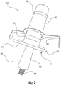
- FIG. 1 shows a centering pin 50 and a centering sleeve 52.
- the centering pin 50 has a mounting portion 54 and a guide portion 56.
- the attachment portion 54 is formed substantially as a threaded pin and carries the guide portion 56 which is tapered and tapers from a side facing away from the attachment portion 54.
- the guide portion 56 is designed in approximately conical shape.
- the centering sleeve 52 has an opening 58, through which the guide section 56 of the centering pin 50 can be inserted into a cavity in the centering sleeve 52.
- an outer contour 60 can essentially be seen from the centering sleeve 52, which basically also indicates the shape of an inner contour of the cavity.
- the centering sleeve 52 is intended to be concreted in a tower segment made of concrete during its manufacture, so that substantially the opening 58 and also the positioning plate 62 is still accessible at a lower abutment surface of the tower segment.
- the positioning plate 62 has two positioning recesses 64.
- two centering lugs 52 are provided for each centering sleeve, each of which engages in the positioning recesses 64 and thus precisely positions the centering sleeve 52.
- the positioning plate 62 achieves the most accurate possible vertical alignment of the centering sleeve 52, in particular with respect to the outer contour 60, which receives the cavity.
- a holding plate 66 is provided, which can also be referred to as a headband and in particular holds the centering sleeve in the casting of concrete in position.
- the circumferential rounded outer webs 68 support a good grip in the concrete.
- FIG. 2 shows the centering pin 50 in a partially inserted into the centering sleeve 52 state, for illustration.
- the centering mandrel 50 namely the guide portion 56 is introduced only when placing two tower segments in the centering sleeve 52, which is already embedded in one of the two tower segment.
Description
- Die vorliegende Erfindung betrifft ein Verfahren zum Errichten eines Turms einer Windenergieanlage.
Verfahren zum Errichten eines Turms einer Windenergieanlage, insbesondere eines Betonturms, sind grundsätzlich bekannt. Zunächst wird ein Betonfundament vorgesehen. Ein Betonturm in Fertigbauweise ist aus mehreren Turmsegmenten zusammengesetzt. Solche Turmsegmente können als rohrförmige und damit zylinderähnliche Elemente, nämlich im Gegensatz zu einem Zylinder mit leicht konischer Form, vorgesehen sein. Bei größeren Turmdurchmessern kommt auch eine Unterteilung in Umfangsrichtung in Betracht, so dass beispielsweise zwei im Querschnitt etwa halbkreisförmige Element oder andere teilkreisförmige Segmente zusammengesetzt werden. - Zunächst werden ein Turmsegment oder mehrere Turmsegmente als erste unterste Turmebene auf dem Fundament aufgesetzt. Es ist wichtig, dass diese erste Ebene sehr sorgfältig ausgerichtet, nämlich ausnivelliert wird.
- Im Weiteren wird der Turm sukzessive aufgebaut, indem weitere Turmsegmente auf den bis dahin aufgebauten Teilturm aufgesetzt werden. Die hierfür notwendigen Arbeiten entstehen somit zunehmend in höherer Höhe. Hierbei muss insbesondere kontrolliert werden, dass das jeweilige neue Turmsegment an exakt der richtigen, vorgesehenen Position angeordnet wird. Mittels eines Kranes wird so jedes Turmsegment sukzessive etwa an seinen Platz gehoben und ein Kranführer führt eine Feinpositionierung des betreffenden Turmsegmentes aus. Die genaue Positionierung jedes Turmsegmentes wird dann von den Arbeitern des Aufbauteams auf der besagten Arbeitsplattform manuell, also mit Muskelkraft vorgenommen. Insbesondere muss das betreffende Turmsegment regelmäßig in die korrekte Position gedreht werden. Das Aufbaupersonal hält das so per Hand ausgerichtete Turmsegment in der korrekten Position und der Kranführer senkt das Turmsegment dann langsam ab, während das Aufbauteam dafür sorgt, dass die ausgerichtete Position beibehalten wird. Es ist dabei zu berücksichtigen, dass ein solches Turmsegment etwa 5 bis 120 t wiegen kann. Es muss somit trotz Einsatz großer Muskelkräfte eine sehr feine Positionierung vorgenommen werden.
- Dieses Verfahren zum Aufsetzen eines weiteren Turmsegmentes ist somit kompliziert, zeit- und arbeitsaufwändig und weist eine gewisse Fehleranfälligkeit. Zudem besteht die Gefahr von Verletzungen für die Arbeiter vor Ort, insbesondere die Gefahr von Quetschungen.
- Ganz allgemein sei auf die Dokumente
US 3,074,564 A ,DE 10 2009 023 538 A1 undDE 20 2010 000 868 U1 verwiesen. DerDE 2009 061 027 offenbart ein Verfahren zum Errichten eines Turms einer Windenergieanlage umfassend die Schritte: - Anordnen eines ersten Turmsegmentes auf einem Fundament oder einem Turmsegment, wobei das erste Turmsegment einen ersten und zweiten Zentrierdorn an seiner Oberseite aufweist,
- Erfindungsgemäß wird ein Verfahren gemäß Anspruch 1 vorgeschlagen. In einem solchen Verfahren, weist ein erster Turmsegment einen ersten und einen zweiten Zentrierdorn an seiner Oberseite auf, wobei der erste Zentrierdorn einen kürzeren Führungsabschnitt als der zweite Zentrierdorn aufweist. Ein solcher Zentrierdorn ist zum Befestigen an einem ersten Turmsegment eines Betonturms einer Windenergieanlage vorgesehen und zum Führen eines zweiten Turmsegmentes des Betonturms beim Absenken des zweiten Turmsegmentes auf das erste Turmsegment. Hierzu weist der Zentrierdorn einen Befestigungsabschnitt zum Befestigen an dem ersten Turmsegment auf, sowie einen Führungsabschnitt zum Führen des zweiten Turmsegmentes. Der Zentrierdorn wird also an dem ersten und damit unteren Turmsegment befestigt. Der Führungsabschnitt ist entsprechend zum Führen des zweiten und damit oberen Turmsegmentes beim Absenken vorbereitet. Ein Windenergieanlagenturm in Fertigbauweise wird aus einer Vielzahl von Turmsegmenten zusammengesetzt, die insbesondere aufeinander aufgesetzt werden. Um insgesamt einen senkrechten und stabilen Turm zu erhalten, müssen alle Segmente sauber aufeinander aufgesetzt werden. Hierzu leistet der vorgeschlagene Zentrierdorn einen Beitrag und erreicht das möglichst präzise Aufeinandersetzen des zweiten Turmsegmentes auf das erste, also des oberen Turmsegmentes auf das untere. Erfindungsgemäß ist der Befestigungsabschnitt des Zentrierdorns mit einem Außengewinde, insbesondere einem Metallgewinde, vorgesehen zum Einschrauben in das erste Turmsegment. Somit ist an dem Turmsegment ein entsprechendes Gewinde zum Einschrauben des Zentrierdorns vorzusehen, das vorteilhaft einem oben beschriebenen Gewinde bzw. Sackloch mit Gewinde zum Aufnehmen einer Tragschlaufe oder anderem Tragmittel nach Art und Größe entspricht, insbesondere damit identisch ist. Der Zentrierdorn kann dann an der Oberseite des ersten Turmsegmentes in das Gewinde eingeschraubt und so befestigt werden. Bei Verwendung eines entsprechenden Gewindes wird hierdurch auch eine genaue Positionierung des Zentrierdorns in dem ersten Turmsegment erreicht. Erfindungsgemäß ist der Führungsabschnitt konisch ausgebildet und verjüngt sich in der zum Befestigungsabschnitt abgewandten Seite. Ist der Zentrierdorn also bestimmungsgemäß oben in das erste Turmsegment eingesetzt, insbesondere eingeschraubt, so verjüngt sich der Führungsabschnitt nach oben. Der Führungsabschnitt kann somit beispielsweise einem Kegelabschnitt entsprechen.
Der Führungsabschnitt kann vorzugsweise aus Kunststoff gefertigt sein. Hierdurch ist eine einfache Ausgestaltung des Zentrierdorns möglich und insbesondere kann seine Form auf einfache Weise hergestellt und reproduziert werden. Insbesondere ist der Führungsabschnitt des Zentrierdorns dazu vorgesehen, in eine korrespondierende Öffnung an der Unterseite des zweiten, also oberen Turmsegmentes, einzugreifen. Erfindungsgemäß, sind der Befestigungsabschnitt und der Führungsabschnitt konzentrisch um eine gemeinsame Achse ausgebildet. Hierdurch ist eine einfache Herstellung, platzsparende Lagerung und Transport möglich. Insbesondere aber vereinfacht dies die Handhabung und gewährleistet möglichst gute Handhabungseigenschaften und insbesondere Eigenschaften zur Führung des oberen Turmsegmentes beim Absenken. - Weiterhin wird ein Zentrierdornpaar bestehend aus zwei unterschiedlich großen Zentrierdornen vorgeschlagen. Dabei können insbesondere die Befestigungsabschnitte, also insbesondere ein Befestigungsabschnitt mit Gewinde die gleiche Größe aufweisen, wohingegen die Führungsabschnitte unterschiedlich groß sind. Bei Anordnung dieser beiden Zentrierdorne, also dieses Zentrierdornpaars an der Oberseite des ersten Turmsegments, also des unteren Turmsegmentes, ragen diese beiden Zentrierdorne somit unterschiedlich hoch über die Oberseite dieses ersten Turmsegmentes hinaus. Zum Ausrichten eines zweiten Turmsegmentes, das auf dem ersten Turmsegment aufgesetzt werden soll, wird das zweite Turmsegment zunächst mittels eines Kranes in eine schwebende Position etwa oberhalb des ersten Turmsegments befördert. Nun kann das zweite Turmsegment langsam so abgesetzt werden, dass eine Zentrierhülse in dem zweiten Turmsegment mit einer nach unten weisenden Öffnung sich oberhalb des größeren Zentrierdorns befindet und soweit abgesenkt wird, dass dieser größere Zentrierdorn zu einem Teil in die korrespondierende Zentrierhülse hineinreicht. Dabei wird dieses zweite Turmsegment nur so weit abgesenkt, dass der kleinere Zentrierdorn, also der Zentrierdorn mit dem kürzeren Führungsabschnitt noch frei ist. Die Unterseite des zweiten Turmsegmentes befindet sich also noch kurz oberhalb der obersten Spitze dieses kleineren Zentrierdorns. Durch den teilweisen Eingriff des größeren Zentrierdorns in seine entsprechende Zentrierhülse kann das zweite Turmsegment nun in eben diesem Bereich um den großen Zentrierdorn geschwenkt werden, bis eine weitere Zentrierhülse oberhalb des kleineren Zentrierdorns angeordnet ist. Nun kann das zweite Turmsegment weiter abgesenkt werden, so dass auch der kleinere Zentrierdorn in seine korrespondierende Hülse eingreift. Nun sind wenigstens zwei Zentrierdorne jeweils in einer Zentrierhülse teilweise eingeführt, nämlich zumindest der oben beschriebene größere und der oben beschriebene kleinere Zentrierdorn. Dieses zweite Turmsegment kann nun weiter abgesenkt werden und dabei übernehmen die vorzugsweise konischen Zentrierdorne die Positionierung des Turmsegmentes. Gemäß einer Ausführung die kein Teil der Erfindung ist, wird somit auch eine Zentrierhülse zum Einbetonieren in ein zweites Turmsegment eines Betonturms einer Windenergieanlage vorgeschlagen. Eine solche Zentrierhülse wird wie oben beschrieben zum Führen des zweiten Turmsegmentes beim Absenken auf ein erstes Turmsegment verwendet und soll dabei mit einem beschriebenen Zentrierdorn zusammenwirken. Eine solche Zentrierhülse weist zumindest einen Hohlraum mit einer Innenkontur zum Aufnehmen eines konischen Zentrierdorns auf und eine Öffnung zum Einführen eines konischen Zentrierdorns. Der Hohlraum und die Öffnung sind dabei insbesondere so ausgestaltet, also sowohl nach Form und Dimensionierung, dass sie mit einem entsprechenden Zentrierdorn zusammenwirken können. Mit anderen Worten sollte der entsprechende Zentrierdorn möglichst passgenau an die Zentrierhülse, also den Hohlraum der Zentrierhülse angepasst sein, dass er beim Einführen in eine Position geleitet wird.
- Die Zentrierhülse weist eine Außenkontur zum Halten der Zentrierhülse in dem Beton des Turmsegmentes auf. Insoweit ist es vorteilhaft, wenn die Außenkontur beispielsweise einen Vorsprung, wie beispielsweise einen umlaufenden Vorsprung aufweist, um ein Herausfallen der Zentrierhülse aus dem ausgehärteten Beton zu vermeiden. Je nach Randbedingungen wie Rauigkeit des Materials der Zentrierhülse und gegebenenfalls weiterer Haltemittel kann es ausreichend sein, wenn die Außenkontur im Wesentlichen der Innenkontur des Hohlraums entspricht.
- Vorzugsweise ist die Zentrierhülse im Wesentlichen aus Kunststoff gefertigt. Das wesentliche bezieht sich darauf, dass als Material für die Zentrierhülse Kunststoff verwendet wird, gegebenenfalls aber Halteelemente, wie ein Haltehaken oder dergleichen beispielsweise aus Metall oder einem anderen Material ergänzt sein können. Insbesondere die Ausgestaltung des Hohlraums ist auf einfache Art und Weise mittels eines Kunststoffmaterials beispielsweise im Spritzgussverfahren zu realisieren.
- Vorzugsweise ist an der Zentrierhülse zudem ein Positionierabschnitt vorgesehen, der zum Positionieren und/oder Befestigen der Zentrierhülse in einer Betonform oder auf einer in dem Zusammenhang verwendeten Auflagefläche einer Betonform ausgebildet ist. Durch diesen Positionierabschnitt wird die Zentrierhülse möglichst exakt zentriert und anschließend erfolgt das Gießen des Betonsegmentes. Dabei muss gewährleistet sein, dass das Gießen des Betons in die entsprechende Segmentform die Zentrierhülse bzw. die Zentrierhülsen in ihrer Position und auch Ausrichtung belässt und nicht verschiebt oder anderweitig bewegt. Entsprechend wird die Zentrierhülse dann in das Turmsegment mit eingegossen. Dabei sollte die Öffnung nicht verschlossen werden, oder ein solcher Verschluss sollte so unwesentlich sein, dass er auf einfache Weise nach dem Aushärten wieder entfernt werden kann. Hierdurch entsteht entsprechend auf einfache Weise ein Turmsegment mit wenigstens einer auf einfache Weise eingearbeiteten Zentrierhülse und damit eine klar definierte Zentrierausnehmung, die mit einem Zentrierdorn zusammenwirken kann.
- Entsprechend wird ein solches Turmsegment eines Betonturms mit einer darin einbetonierten Zentrierhülse vorgeschlagen.
Vorteilhaft ist somit, einen Zentriersatz vorzusehen, der wenigstens einen Zentrierdorn und eine daran angepasste Zentrierhülse aufweist. - Nachfolgend wird die Erfindung an Hand von Ausführungsbeispielen unter Bezugnahme auf die begleitenden Figuren beispielhaft erläutert.
- Figur 1
- zeigt einen Zentrierdorn und eine Zentrierhülse in einer perspektivischen Ansicht.
- Figur 2
- zeigt den Zentrierdorn und die Zentrierhülse der
Figur 1 in einem teilweise zusammengesetzten Zustand. -
Figur 1 zeigt einen Zentrierdorn 50 und eine Zentrierhülse 52. Der Zentrierdorn 50 weist einen Befestigungsabschnitt 54 und einen Führungsabschnitt 56 auf. Der Befestigungsabschnitt 54 ist im Wesentlichen als Gewindestift ausgebildet und trägt den Führungsabschnitt 56, der konisch ausgebildet ist und sich von einer zum Befestigungsabschnitt 54 abweisenden Seite hin verjüngt. Der Führungsabschnitt 56 ist dabei in etwa kegelförmig ausgestaltet.
Die Zentrierhülse 52 zeigt eine Öffnung 58, durch die der Führungsabschnitt 56 des Zentrierdorns 50 in einen Hohlraum in der Zentrierhülse 52 eingeführt werden kann. In der Figur 5 ist von der Zentrierhülse 52 im Wesentlichen auch eine Außenkontur 60 zu erkennen, die im Grunde auch die Form einer Innenkontur des Hohlraums andeutet.
Die Zentrierhülse 52 ist dazu vorgesehen, in einem Turmsegment aus Beton bei dessen Herstellung mit einbetoniert zu werden, so dass im Wesentlichen die Öffnung 58 und zudem die Positionierungsplatte 62 an einer unteren Stoßfläche des Turmsegmentes noch zugänglich ist. Zum Einbetonieren weist die Positionierungsplatte 62 zwei Positionierungsausnehmungen 64 auf. Vor dem Einbetonieren wird die Zentrierhülse 52 mit der Positionierungsplatte 62 nach unten weisend auf eine ebene Fläche aufgesetzt, auf der auch eine Form zum Gießen des Turmsegmentes angeordnet wird. Auf dieser ebenen Flächen bzw. Platte sind für jede Zentrierhülse 52 jeweils zwei Zentriernasen vorgesehen, die jeweils in die Positionierungsausnehmungen 64 eingreifen und die Zentrierhülse 52 somit exakt positionieren. Die Positionierungsplatte 62 erreicht dabei eine möglichst genaue senkrechte Ausrichtung der zentrierhülse 52, insbesondere bezogen auf die Außenkontur 60, die den Hohlraum aufnimmt.
Zum Halten der Zentrierhülse 52 in dem Beton ist ein Halteblech 66 vorgesehen, der auch als Haltebügel bezeichnet werden kann und insbesondere die Zentrierhülse beim Vergießen des Beton in Position hält. Zudem unterstützen auch die umlaufenden abgerundeten Außenstege 68 eine guten Halt in dem Beton. -
Figur 2 zeigt den Zentrierdorn 50 in einem teilweise in die Zentrierhülse 52 eingesetzten Zustand, zur Veranschaulichung. Im Gebrauch wird der Zentrierdorn 50, nämlich der Führungsabschnitt 56 erst beim Aufeinandersetzen zweier Turmsegmente in die Zentrierhülse 52 eingeführt, die dabei bereits in einen der beiden Turmsegment einbetoniert ist.
wobei das zweite Turmsegment so teilweise auf das erste Turmsegment abgesenkt wird, dass ein erster Zentrierdorn in eine entsprechende erste Zentrierausnehmung an der Unterseite des zweiten Turmsegments teilweise eingreift. Der vorliegenden Erfindung liegt somit die Aufgabe zugrunde, wenigstens eines der oben aufgezeigten Probleme zu beheben oder zu verringern, insbesondere den Aufbau eines Turms einer Windenergieanlage effizienter zu gestalten, insbesondere den Aufbau eines Betonturms. Zumindest soll eine alternative Lösung vorgeschlagen werden.
Claims (4)
- Verfahren zum Errichten eines Turms einer Windenergieanlage umfassend die Schritte:- Anordnen eines ersten Turmsegmentes auf einem Fundament oder einem Turmsegment,
wobei das erste Turmsegment einen ersten und zweiten Zentrierdorn an seiner Oberseite aufweist, wobei der erste Zentrierdorn einen kürzeren Führungsabschnitt aufweist als der zweite Zentrierdorn,
wobei der erste und zweite Zentrierdorn zum Befestigen an einem ersten Turmsegment eines Betonturms einer Windenergieanlage und zum Führen eines zweiten Turmsegmentes des Betonturms beim Absenken des zweiten Turmsegments auf das erste Turmsegment ausgestaltet sind und einen Befestigungsabschnitt zum Befestigen an dem ersten Turmsegment, einen Führungsabschnitt zum Führen des zweiten Turmsegments aufweist,
wobei der Befestigungsabschnitt ein Außengewinde, insbesondere ein Metallgewinde aufweist zum Einschrauben in das erste Turmsegment,
wobei der Führungsabschnitt konisch ausgebildet ist und sich in einer dem Befestigungsabschnitt abgewandten Richtung verjüngt,
wobei der Befestigungsabschnitt und der Führungsabschnitt konzentrisch um eine gemeinsame Achse ausgebildet sind,- das zweite Turmsegment so teilweise auf das erste Turmsegment abgesenkt wird, dass ein erster Zentrierdorn in eine entsprechende erste Zentrierausnehmung an der Unterseite des zweiten Turmsegments teilweise eingreift,- das zweite Turmsegment um eine Achse des ersten Zentrierdorns und der entsprechenden ersten Zentrieraufnahme geschwenkt wird, bis eine zweite Zentrieraufnahme an der Unterseite des zweiten Turmsegments etwa oberhalb des zweiten Zentrierdorns angeordnet ist,- das zweite Turmsegment vollständig abgesenkt wird, wobei der erste und zweite Zentrierdorn so in die erste bzw. zweite Zentrierausnehmung des zweiten Turmsegmentes eingreift, dass das zweite Turmsegment in seine gewünschte, ausgerichtete Position auf dem ersten Turmsegment geführt wird. - Verfahren nach Anspruch 1, wobei das zweite Turmsegment oder ein anderes Turmsegment mit einer Hebevorrichtung angehoben und abgesetzt wird, wobei die Hebevorrichtung, insbesondere Traverse, zum Heben eines ersten Turmsegmentes eines Betonturms einer Windenergieanlage mittels eines Krans ausgeführt ist, umfassend:- wenigstens ein Befestigungsmittel zum Befestigen des Turmsegmentes an der Hebevorrichtung und- wenigstens eine Auslösevorrichtung zum Lösen einer Verbindung zwischen der Hebevorrichtung und dem Turmsegment.
- Verfahren nach Anspruch 1 oder 2, wobei
der Führungsabschnitt aus Kunststoff gefertigt ist. - Verfahren nach Anspruch 1, wobei der erste Zentrierdorn einen um 20% - 70% kürzeren Führungsabschnitt aufweist als der zweite Zentrierdorn, vorzugsweise um 40% - 60% kürzer, wobei die Befestigungsabschnitte beider Zentrierdorne vorzugsweise die gleiche Größe aufweisen.
Applications Claiming Priority (2)
| Application Number | Priority Date | Filing Date | Title |
|---|---|---|---|
| DE102011003164A DE102011003164A1 (de) | 2011-01-26 | 2011-01-26 | Verfahren und Vorrichtung zum Errichten eines Turms einer Windenergieanlage |
| EP12700685.6A EP2556008B1 (de) | 2011-01-26 | 2012-01-18 | Vorrichtung und verfahren zum errichten eines turms einer windenergieanlage |
Related Parent Applications (2)
| Application Number | Title | Priority Date | Filing Date |
|---|---|---|---|
| EP12700685.6A Division EP2556008B1 (de) | 2011-01-26 | 2012-01-18 | Vorrichtung und verfahren zum errichten eines turms einer windenergieanlage |
| EP12700685.6A Division-Into EP2556008B1 (de) | 2011-01-26 | 2012-01-18 | Vorrichtung und verfahren zum errichten eines turms einer windenergieanlage |
Publications (2)
| Publication Number | Publication Date |
|---|---|
| EP2803617A1 EP2803617A1 (de) | 2014-11-19 |
| EP2803617B1 true EP2803617B1 (de) | 2017-12-27 |
Family
ID=45509505
Family Applications (4)
| Application Number | Title | Priority Date | Filing Date |
|---|---|---|---|
| EP14180212.4A Active EP2803616B1 (de) | 2011-01-26 | 2012-01-18 | Arbeitsbühnenvorrichtung zum Arbeiten in verändlicher Höhe und Verfahren dafür |
| EP14180214.0A Active EP2803617B1 (de) | 2011-01-26 | 2012-01-18 | Verfahren zum Errichten eines Turms einer Windenergieanlage |
| EP14180218.1A Active EP2805909B1 (de) | 2011-01-26 | 2012-01-18 | Wärmevorrichtung |
| EP12700685.6A Active EP2556008B1 (de) | 2011-01-26 | 2012-01-18 | Vorrichtung und verfahren zum errichten eines turms einer windenergieanlage |
Family Applications Before (1)
| Application Number | Title | Priority Date | Filing Date |
|---|---|---|---|
| EP14180212.4A Active EP2803616B1 (de) | 2011-01-26 | 2012-01-18 | Arbeitsbühnenvorrichtung zum Arbeiten in verändlicher Höhe und Verfahren dafür |
Family Applications After (2)
| Application Number | Title | Priority Date | Filing Date |
|---|---|---|---|
| EP14180218.1A Active EP2805909B1 (de) | 2011-01-26 | 2012-01-18 | Wärmevorrichtung |
| EP12700685.6A Active EP2556008B1 (de) | 2011-01-26 | 2012-01-18 | Vorrichtung und verfahren zum errichten eines turms einer windenergieanlage |
Country Status (25)
| Country | Link |
|---|---|
| US (1) | US9534416B2 (de) |
| EP (4) | EP2803616B1 (de) |
| JP (3) | JP5860902B2 (de) |
| KR (3) | KR20150090266A (de) |
| CN (3) | CN103476696B (de) |
| AR (1) | AR085029A1 (de) |
| AU (1) | AU2012210698B2 (de) |
| BR (1) | BR112013018604A2 (de) |
| CA (1) | CA2823982C (de) |
| CL (1) | CL2013002121A1 (de) |
| CY (2) | CY1116401T1 (de) |
| DE (1) | DE102011003164A1 (de) |
| DK (4) | DK2805909T3 (de) |
| ES (3) | ES2611830T3 (de) |
| HR (2) | HRP20150718T1 (de) |
| HU (2) | HUE030304T2 (de) |
| LT (1) | LT2805909T (de) |
| MX (1) | MX336620B (de) |
| PL (2) | PL2556008T3 (de) |
| PT (3) | PT2556008E (de) |
| RS (2) | RS54062B1 (de) |
| SI (2) | SI2556008T1 (de) |
| TW (1) | TWI480453B (de) |
| WO (1) | WO2012101023A2 (de) |
| ZA (1) | ZA201304951B (de) |
Families Citing this family (41)
| Publication number | Priority date | Publication date | Assignee | Title |
|---|---|---|---|---|
| WO2014073063A1 (ja) * | 2012-11-08 | 2014-05-15 | ベステラ株式会社 | 集合形煙突解体用足場装置及びその装置を用いた集合形煙突の解体方法 |
| DE102012221453A1 (de) * | 2012-11-23 | 2014-05-28 | Wobben Properties Gmbh | Greifeinrichtung zum Handhaben von Bewehrungskörben für Turmsegmente einer Windenergieanlage |
| DK2824057T3 (en) | 2013-07-11 | 2017-09-11 | Siemens Ag | Lifting of a tower segment |
| PL3572366T3 (pl) * | 2013-07-17 | 2022-03-21 | Alimak Group Management Ab | System windowy |
| CN103939298B (zh) * | 2014-04-01 | 2016-04-13 | 北京金风科创风电设备有限公司 | 用于混凝土塔架拼装的结构 |
| CN104213714B (zh) * | 2014-08-27 | 2016-03-09 | 中国建筑第二工程局有限公司 | 一种超大型屋架的提升吊点加固结构及吊装施工方法 |
| CA2963587A1 (en) * | 2014-10-06 | 2016-04-14 | Vestas Wind Systems A/S | Hinged tower segments and transport method |
| CN104631839B (zh) * | 2015-01-29 | 2016-08-24 | 浙江勤业建工集团有限公司 | 超高超重大跨度空中连廊整体提升施工方法 |
| CN104803308B (zh) * | 2015-04-28 | 2017-01-18 | 中国水利水电第八工程局有限公司 | 用于钢管加劲环拼装的吊装装置 |
| CN105119189A (zh) * | 2015-08-27 | 2015-12-02 | 国家电网公司 | 一种超长瓷片式绝缘子串吊装架 |
| CN105119190A (zh) * | 2015-08-27 | 2015-12-02 | 国家电网公司 | 一种自锁式瓷片式绝缘子吊装架 |
| EP3329071B1 (de) | 2015-08-31 | 2022-03-16 | Siemens Gamesa Renewable Energy, Inc. | System und verfahren zur installation eines spanngliedes in einem windturbinenturm |
| DE102016200160A1 (de) * | 2016-01-08 | 2017-07-13 | Wobben Properties Gmbh | Hebevorrichtung zum Heben einer Komponente einer Windenergieanlage und Verfahren zum Montieren von Komponenten einer Windenergieanlage |
| GB2551481A (en) * | 2016-06-08 | 2017-12-27 | John Reed Patrick | A sheeting system |
| CN106337785B (zh) * | 2016-09-29 | 2019-01-25 | 中车株洲电力机车研究所有限公司 | 风力发电机组风轮内葫芦辅助拆装工具及方法 |
| EP3510280B1 (de) * | 2016-11-11 | 2020-09-16 | Siemens Gamesa Renewable Energy A/S | Transportanordnung |
| CN109923303B (zh) * | 2016-11-23 | 2020-07-31 | 菱重维斯塔斯海上风力有限公司 | 用于对准风轮机结构部件的方法和组件 |
| CN106640558B (zh) * | 2016-12-30 | 2019-04-12 | 北京金风科创风电设备有限公司 | 风力涡轮机的变桨轴承、叶片、叶轮及连接方法 |
| CN106903014A (zh) * | 2017-02-28 | 2017-06-30 | 李金平 | 一种喷涂行业用定心转盘 |
| CN106744252B (zh) * | 2017-03-27 | 2018-09-21 | 江苏中车电机有限公司 | 用于mw级直驱永磁风力发电机转子吊运工装及使用方法 |
| CN107152021B (zh) * | 2017-06-06 | 2023-03-28 | 中国石油天然气集团公司 | 一种u形管桩护甲安装工具 |
| EP3450752B1 (de) | 2017-09-04 | 2020-06-17 | Siemens Gamesa Renewable Energy A/S | Windturbine mit einer zugangsanordnung für eine gondel |
| CN107953975B (zh) * | 2017-11-22 | 2023-06-02 | 自然资源部第二海洋研究所 | 船用机械臂止荡机构 |
| CN109058052B (zh) * | 2018-08-29 | 2020-08-21 | 江苏仕沃精密机械科技有限公司 | 新能源风力发电设备的集成式固定安装架 |
| CN109809287B (zh) * | 2019-03-18 | 2020-05-12 | 哈尔滨电机厂有限责任公司 | 一种用于周向装配的对称起吊装置的使用方法 |
| CN110565934A (zh) * | 2019-07-26 | 2019-12-13 | 江苏兴厦建设工程集团有限公司 | 一种建筑外墙悬吊式人货电梯施工平台及其安装方法 |
| DE102019122021A1 (de) | 2019-08-15 | 2021-02-18 | Wobben Properties Gmbh | Montagetraverse und Verfahren zum Einziehen von kabelförmigen Elementen, insbesondere von Spanngliedern, entlang eines Turms einer Windenergieanlage |
| JP6798720B1 (ja) * | 2019-09-30 | 2020-12-09 | 村田油圧機械株式会社 | 連絡ブリッジ用の伸縮アクチュエータ |
| JP6798721B1 (ja) * | 2019-09-30 | 2020-12-09 | 村田油圧機械株式会社 | 連絡ブリッジ用の水平回動アクチュエータ |
| JP6882795B2 (ja) * | 2019-09-30 | 2021-06-02 | 村田油圧機械株式会社 | 連絡ブリッジ |
| CN111039152B (zh) * | 2019-12-31 | 2021-01-26 | 烟台腾泰环保建材有限公司 | 一种混凝土预制构件 |
| CN111980865B (zh) * | 2020-07-29 | 2021-11-12 | 上海市机电设计研究院有限公司 | 减小预制混凝土筒片错动的筒节吊装方法 |
| CN111997432B (zh) * | 2020-07-29 | 2021-12-14 | 上海市机电设计研究院有限公司 | 预制混凝土塔筒的施工平台提升装置及方法 |
| CN113023540B (zh) * | 2021-03-15 | 2022-03-01 | 合肥中科离子医学技术装备有限公司 | 一种用于回旋加速器整机的吊装运输一体式装置 |
| CN113090037A (zh) * | 2021-04-01 | 2021-07-09 | 浙江明康工程咨询有限公司 | 一种卸料平台的预警方法及系统 |
| CN113503047A (zh) * | 2021-07-31 | 2021-10-15 | 中冶(上海)钢结构科技有限公司 | 钢结构提升过程中牵引调整高空位置偏移的方法 |
| CN113756647B (zh) * | 2021-09-04 | 2022-11-08 | 中铁十五局集团有限公司 | 一种线路铁塔分段结构的施工方法及其装置 |
| CN113944313B (zh) * | 2021-11-03 | 2023-04-11 | 上海建工五建集团有限公司 | 悬挑型钢顶撑限位装置、悬挑钢平台及其施工方法 |
| CN114108996B (zh) * | 2021-11-26 | 2023-06-06 | 中煤西安设计工程有限责任公司 | 一种无楼板砖砌填充墙的施工装置及方法 |
| CN115285854B (zh) * | 2022-09-28 | 2022-12-02 | 中国能源建设集团山西电力建设有限公司 | 大型圆柱形罐体的低空拼装分节抬升的装配方法 |
| CN117703164B (zh) * | 2024-02-05 | 2024-04-09 | 辽宁省送变电工程有限公司 | 高低铁塔塔腿段组立自动提升装置 |
Family Cites Families (52)
| Publication number | Priority date | Publication date | Assignee | Title |
|---|---|---|---|---|
| US3074564A (en) * | 1961-03-01 | 1963-01-22 | Chicago Bridge & Iron Co | Mast extension jib |
| DE1251803B (de) * | 1963-12-05 | 1967-10-12 | Siemens Aktiengesellschaft, Berlin und München München | Verfah ren und Einrichtung zum Regenerieren von phasenmodulierten Impulsfolgen |
| CH508507A (de) * | 1969-05-28 | 1971-06-15 | Von Roll Ag | Zahnstange für eine Fahrschiene für Hängebahnen |
| JPS5830882Y2 (ja) * | 1978-06-21 | 1983-07-08 | 住友金属工業株式会社 | 大型コンクリ−ト構造体用吊筋 |
| SU958296A1 (ru) | 1980-06-12 | 1982-09-15 | Республиканское Проектно-Технологическое Производственное Объединение "Росоргтехстрой" | Захват-кантователь дл изделий с цапфами |
| DE8424193U1 (de) * | 1984-08-16 | 1985-12-12 | Ernst Peiniger GmbH Unternehmen für Bautenschutz, 4300 Essen | Arbeitsplatzverschlag |
| EP0688922B1 (de) * | 1994-06-23 | 1998-04-22 | HALFEN GmbH & CO. Kommanditgesellschaft | Transportanker, insbesondere für Betonfertigteile und in den Transportanker einschraubbarer Lastaufnehmer |
| TW253924B (en) | 1994-09-14 | 1995-08-11 | Nippon Kotetsu Kokusai Kk | Elevatable work facility |
| JPH08303441A (ja) * | 1995-05-01 | 1996-11-19 | Aioi Seiki Kk | ガイド兼ロック機構付きコネクタ装置 |
| CA2362179A1 (en) * | 1998-02-04 | 1999-08-12 | Stephen L. Heston | Palletizing device |
| DE19857744B4 (de) * | 1998-12-15 | 2007-05-16 | Schuler Pressen Gmbh & Co | Presse mit Stempelverstellung, insbesondere zur Massivumformung |
| JP2000283019A (ja) * | 1999-03-31 | 2000-10-10 | Pc Bridge Co Ltd | コンクリート製風車支持タワー及びその構築方法 |
| DE10025074B4 (de) | 2000-05-20 | 2006-11-09 | Hailo-Werk Rudolf Loh Gmbh & Co. Kg | Einrichtung zum Befördern von Personen |
| US6782667B2 (en) | 2000-12-05 | 2004-08-31 | Z-Tek, Llc | Tilt-up and telescopic support tower for large structures |
| DE10104351A1 (de) | 2001-02-01 | 2002-08-22 | Ingenieurgesellschaft Foerder | Aufzug mit auf der Aufzugskabine mitfahrender Antriebseinheit und Steuereinheit |
| US6625940B2 (en) * | 2001-02-02 | 2003-09-30 | Wallace D. Sanger | Concrete building module with module lifting means and method |
| DE10160022A1 (de) * | 2001-12-06 | 2003-06-18 | Gen Electric | Verfahren zum Herstellen eines Turms einer Windkraftanlage, mit diesem Verfahren hergestellter Turm und Bauelemente zur Herstellung eines Turms |
| DE10163538B4 (de) * | 2001-12-21 | 2004-09-30 | Norbert Plambeck | Vorrichtung und Verfahren zum Transport und zur Errichtung von Offshore-Windenergieanlagen |
| GB2394498B (en) * | 2002-10-23 | 2006-08-09 | Engineering Business Ltd | Mounting of offshore structures |
| JP2004156478A (ja) * | 2002-11-05 | 2004-06-03 | Kashiwabara Painting Works Co Ltd | 独立型塔体構造物の作業用足場装置及び作業用足場設置工法 |
| CN100445552C (zh) * | 2003-12-30 | 2008-12-24 | Pp能源有限责任公司 | 用于抵达位于地面上方的结构的设备 |
| GB0500619D0 (en) | 2005-01-13 | 2005-02-23 | Severfield Rowen Plc | Improvements relating to construction |
| CN101614083B (zh) * | 2005-01-19 | 2014-09-24 | Iti苏格兰有限公司 | 夹具、自移式爬升装置和联接夹具与管形件的方法 |
| US20060213145A1 (en) * | 2005-03-22 | 2006-09-28 | Haller Mark E | Lattice-skin hybrid tower |
| JP2007046292A (ja) * | 2005-08-09 | 2007-02-22 | Oriental Construction Co Ltd | タワー構築用ブロック |
| JP4701047B2 (ja) * | 2005-09-07 | 2011-06-15 | 株式会社竹中工務店 | 風力発電タワーの構築方法 |
| TWM296876U (en) | 2006-03-07 | 2006-09-01 | Runhorn Pretech Eng Co Ltd | Wall structure preset hanging point |
| WO2008000565A2 (en) | 2006-06-29 | 2008-01-03 | Vestas Wind Systems A/S | A tower construction for a wind turbine |
| EP2035316B1 (de) | 2006-06-30 | 2010-12-15 | Vestas Wind Systems A/S | Hubeinrichtung zur handhabung einer windturbinenkomponente und verfahren zur handhabung einer windturbinenkomponente |
| BRPI0719789A8 (pt) * | 2006-10-02 | 2017-08-15 | Wind Tower Systems Llc | Sistema de levantamento e aparelho para construir e vedar torres de turbina eólica. |
| KR20090011746A (ko) * | 2007-07-27 | 2009-02-02 | 주식회사 피엔에이치 | 자동 개방형 샤클 조립체의 안전장치 |
| AU2008221636A1 (en) * | 2007-10-11 | 2009-04-30 | General Electric Company | Wind tower and method of assembling the same |
| WO2009101697A1 (ja) * | 2008-02-15 | 2009-08-20 | Sakuraigiken Co., Ltd. | 風力発電設備の風車羽根のメンテナンス工法及びメンテナンス装置 |
| US20090223163A1 (en) | 2008-03-10 | 2009-09-10 | Shu Ching Quek | Wind Turbine Tower Including An Induction Brazed Joint And A Method Of Fabricating The Wind Turbine Tower |
| JP5069171B2 (ja) * | 2008-05-22 | 2012-11-07 | 鹿島建設株式会社 | 洋上風力発電の基礎と上部工の接合部構造および上部工の据付方法 |
| TW201016961A (en) | 2008-10-16 | 2010-05-01 | Mitsubishi Heavy Ind Ltd | Wind-powered electric generator |
| DK2256338T3 (en) * | 2008-11-03 | 2014-02-17 | Siemens Ag | Foundation, especially for a wind turbine and wind turbine |
| EP2192245B1 (de) * | 2008-11-27 | 2012-05-30 | Vestas Wind Systems A/S | Turm für eine Windturbine und Verfahren zu dessen Herstellung |
| CN101481069B (zh) * | 2008-12-10 | 2012-09-05 | 三一电气有限责任公司 | 一种攀爬系统和攀爬起吊系统 |
| SE534035C2 (sv) * | 2009-04-08 | 2011-04-12 | Ncc Construction Sverige Ab | Förfarande för byggande av vindkraftverk |
| DE102009061027A1 (de) * | 2009-04-19 | 2010-10-28 | Timber Tower Gmbh | Turm für eine Windkraftanlage |
| CA2698710A1 (en) * | 2009-05-05 | 2010-11-05 | Fws Technologies Holdings Ltd. | Slip formed concrete wind turbine tower |
| DE102009023538A1 (de) * | 2009-05-30 | 2010-12-09 | Kai Berkenbrink | Turm einer Windkraftanlage, Windkraftanlage sowie Verfahren zum Anheben von Komponenten einer Windkraftanlage |
| NL1037052C2 (en) * | 2009-06-19 | 2010-12-21 | Darwind Holding B V | A method of finishing a tower section of a wind turbine, a finished tower section of a wind turbine, and a method of transporting a tower section of a wind turbine. |
| CN102482892B (zh) | 2009-07-13 | 2014-10-08 | Vsl国际股份公司 | 伸缩塔组件和方法 |
| DE202010000868U1 (de) * | 2009-07-20 | 2010-12-02 | Wader-Wittis Gmbh | Vorrichtung zum Transport und zur Montage von Windkraftanlagen |
| US8678455B2 (en) * | 2009-07-24 | 2014-03-25 | Siemens Aktiengesellschaft | Lifting fitting |
| US8596700B2 (en) * | 2009-08-14 | 2013-12-03 | Mjt Holdings, Llc | Tower erection lift kit tools |
| DE102009051425A1 (de) * | 2009-10-30 | 2011-05-05 | Voith Patent Gmbh | Strömungskraftwerk und Verfahren für dessen Erstellung |
| US8544924B2 (en) * | 2009-11-06 | 2013-10-01 | Engineered Lifting Technologies, Inc. | Lifting assembly |
| US8434799B2 (en) * | 2010-06-03 | 2013-05-07 | Robert J. Reger | Synthetic fiber sling and roller system for carrying and positioning a load |
| DK2402278T3 (da) * | 2010-06-29 | 2012-12-10 | Siemens Ag | Indretning til løftning af et tårnvægafsnit af en vindturbine og fremgangsmåde til løftning af et tårnvægafsnit af en vindturbine |
-
2011
- 2011-01-26 DE DE102011003164A patent/DE102011003164A1/de not_active Withdrawn
-
2012
- 2012-01-18 DK DK14180218.1T patent/DK2805909T3/en active
- 2012-01-18 DK DK14180214.0T patent/DK2803617T3/en active
- 2012-01-18 KR KR1020157019627A patent/KR20150090266A/ko not_active Application Discontinuation
- 2012-01-18 CN CN201280006757.0A patent/CN103476696B/zh active Active
- 2012-01-18 BR BR112013018604-6A patent/BR112013018604A2/pt not_active Application Discontinuation
- 2012-01-18 DK DK12700685.6T patent/DK2556008T3/en active
- 2012-01-18 ES ES14180218.1T patent/ES2611830T3/es active Active
- 2012-01-18 LT LTEP14180218.1T patent/LT2805909T/lt unknown
- 2012-01-18 ES ES14180214.0T patent/ES2658437T3/es active Active
- 2012-01-18 AU AU2012210698A patent/AU2012210698B2/en not_active Ceased
- 2012-01-18 KR KR1020157019628A patent/KR20150090267A/ko not_active Application Discontinuation
- 2012-01-18 PT PT127006856T patent/PT2556008E/pt unknown
- 2012-01-18 EP EP14180212.4A patent/EP2803616B1/de active Active
- 2012-01-18 EP EP14180214.0A patent/EP2803617B1/de active Active
- 2012-01-18 RS RS20150408A patent/RS54062B1/en unknown
- 2012-01-18 EP EP14180218.1A patent/EP2805909B1/de active Active
- 2012-01-18 US US13/981,713 patent/US9534416B2/en active Active
- 2012-01-18 PL PL12700685T patent/PL2556008T3/pl unknown
- 2012-01-18 CN CN201510309673.XA patent/CN105020228B/zh not_active Expired - Fee Related
- 2012-01-18 ES ES12700685.6T patent/ES2541637T3/es active Active
- 2012-01-18 PT PT141802140T patent/PT2803617T/pt unknown
- 2012-01-18 SI SI201230211T patent/SI2556008T1/sl unknown
- 2012-01-18 PT PT141802181T patent/PT2805909T/pt unknown
- 2012-01-18 PL PL14180218T patent/PL2805909T3/pl unknown
- 2012-01-18 CN CN201510309176.XA patent/CN105035939B/zh not_active Expired - Fee Related
- 2012-01-18 SI SI201230805A patent/SI2805909T1/sl unknown
- 2012-01-18 HU HUE14180218A patent/HUE030304T2/en unknown
- 2012-01-18 KR KR1020137022160A patent/KR101665169B1/ko active IP Right Grant
- 2012-01-18 MX MX2013008532A patent/MX336620B/es unknown
- 2012-01-18 DK DK14180212.4T patent/DK2803616T3/da active
- 2012-01-18 EP EP12700685.6A patent/EP2556008B1/de active Active
- 2012-01-18 CA CA2823982A patent/CA2823982C/en not_active Expired - Fee Related
- 2012-01-18 WO PCT/EP2012/050729 patent/WO2012101023A2/de active Application Filing
- 2012-01-18 JP JP2013550827A patent/JP5860902B2/ja active Active
- 2012-01-18 HU HUE12700685A patent/HUE026787T2/en unknown
- 2012-01-18 RS RS20160924A patent/RS55347B1/sr unknown
- 2012-01-19 TW TW101102283A patent/TWI480453B/zh not_active IP Right Cessation
- 2012-01-25 AR ARP120100242A patent/AR085029A1/es active IP Right Grant
-
2013
- 2013-07-03 ZA ZA2013/04951A patent/ZA201304951B/en unknown
- 2013-07-24 CL CL2013002121A patent/CL2013002121A1/es unknown
-
2014
- 2014-10-31 JP JP2014223324A patent/JP6038098B2/ja active Active
- 2014-10-31 JP JP2014223332A patent/JP6282572B2/ja active Active
-
2015
- 2015-06-12 CY CY20151100516T patent/CY1116401T1/el unknown
- 2015-07-02 HR HRP20150718TT patent/HRP20150718T1/hr unknown
-
2016
- 2016-11-02 HR HRP20161445TT patent/HRP20161445T1/hr unknown
- 2016-12-09 CY CY20161101275T patent/CY1118427T1/el unknown
Non-Patent Citations (2)
| Title |
|---|
| "TECHNISCHE Daten - Wegertseder GmbH - www.wegertseder.com DIN 7977 / ISO 8737 Kegelstifte mit Gewindezapfen", 26 April 2016 (2016-04-26), XP055268693, Retrieved from the Internet <URL:http://www.schrauben-lexikon.de/download/tiso_8737.pdf> [retrieved on 20160426] * |
| ANONYMOUS: "Taper pins with external thread, unhardened", 26 April 2016 (2016-04-26), XP055268719, Retrieved from the Internet <URL:http://www.fasten.it/en/tech267/pins_-_cotter_pins_-_parallel_keys/dowel_and_taper_pins/taper_pins_with_external_thread__unhardened/> [retrieved on 20160426] * |
Also Published As
Similar Documents
| Publication | Publication Date | Title |
|---|---|---|
| EP2803617B1 (de) | Verfahren zum Errichten eines Turms einer Windenergieanlage | |
| EP3004467B1 (de) | Betonfundament und verfahren zur herstellung eines betonfundaments für einen windkraftturm sowie positioniervorrichtung zur positionierung von hüllrohren in einem betonfundament | |
| EP2723544B1 (de) | Turmfertigung | |
| AT516118B1 (de) | Bewehrungselement sowie Verfahren zum Herstellen eines Bewehrungselementes | |
| DE102008055607A1 (de) | Verfahren zum Errichten eines segmentierten Turms aus Spannbeton für Windkraftanlagen und Turm für Windkraftanlagen | |
| EP1607364B1 (de) | Kranballastierungssystem | |
| WO2013117182A1 (de) | Verfahren zum handhaben von turmsegmenten für einen turm und vorrichtung zur handhabung von turmsegmenten | |
| DE102012025629A1 (de) | Abstandhalter zum Einsetzen in mit einem Basismaterial herzustellende Bauteile mit integrierter textiler Bewehrung | |
| WO2019234488A2 (de) | GIESSβFORM FÜR EIN RINFÖRMIGES BETONMODUL, VERFAHREN ZUM FERTIGEN EINES BETONMODULS MIT DER GIESSβFORM UND MONTAGESYSTEM ZUR FERTIGUNG EINES AUS DEN BETONMODULEN BESTEHENDEN SCHWEIMMENDEN FUNDAMENTS EINER SCHWIMMENDEN WINDENERGIEANLAGE | |
| DE102009019709A1 (de) | Verfahren zum Errichten eines Turmes und Turm | |
| EP3208404B1 (de) | Verfahren und vorrichtung zur montage eines rohrturmsegments | |
| EP3074183B1 (de) | Stegsetzvorrichtung, steg und fertigungsverfahren für ein rotorblatt einer windenergieanlage | |
| EP2712985B1 (de) | Verfahren zum Erstellen eines Turms, insbesondere eines Turms für eine Windkraftanlage | |
| DE102008060213B3 (de) | Vorrichtung zur Befestigung eines Kerns an einer Sandform | |
| EP3543430A1 (de) | Positioniervorrichtung und verfahren zur herstellung eines bewehrten baustoffkörpers | |
| DE2724398A1 (de) | Verfahren zum herstellen eines fundamentes, insbesondere fuer schornsteine o.ae. bauwerke, z.b. saeulen, masten, tuerme o.dgl. lehrenartige vorrichtung zur durchfuehrung dieses verfahrens sowie in verbindung mit der lehrenartigen vorrichtung bei dem verfahren zu verwendende verankerungsstaebe | |
| EP3939759A1 (de) | Haltevorrichtung zum fixieren von betonbauteilen in einer form | |
| DE102004010927B4 (de) | Verfahren und Vorrichtung zum Erstellen von insbesondere viertel-, halb- oder vollgewendelten Ortbeton-Treppen | |
| DE102017203645B4 (de) | System zum Vorspannen eines Turmbauwerks | |
| DE4324522C1 (de) | Vorrichtung und Verfahren zum Herstellen geschoßhoher Kaminelemente | |
| DE102017115141A1 (de) | Verfahren zur Herstellung einer Betonschalung für ein Turmsegment und Verfahren zur Herstellung eines Turmsegments für einen Turm einer Windenergieanlage | |
| DE2625156C3 (de) | Pfahlverbindung für je zwei Abschnitte eines Gründungspfahls, Zugpfahls o.dgl. aus Stahlbeton | |
| EP3163075A1 (de) | Windenergieanlage, lastenverteilungssystem einer windenergieanlage und verfahren zum errichten eines turms einer windenergieanlage | |
| DE102018000973A1 (de) | Vorrichtung zum Vulkanisieren von Reifen | |
| DE2805016A1 (de) | Verfahren und vorrichtung zur herstellung von stahlbetonbauteilen |
Legal Events
| Date | Code | Title | Description |
|---|---|---|---|
| PUAI | Public reference made under article 153(3) epc to a published international application that has entered the european phase |
Free format text: ORIGINAL CODE: 0009012 |
|
| 17P | Request for examination filed |
Effective date: 20140807 |
|
| AC | Divisional application: reference to earlier application |
Ref document number: 2556008 Country of ref document: EP Kind code of ref document: P |
|
| AK | Designated contracting states |
Kind code of ref document: A1 Designated state(s): AL AT BE BG CH CY CZ DE DK EE ES FI FR GB GR HR HU IE IS IT LI LT LU LV MC MK MT NL NO PL PT RO RS SE SI SK SM TR |
|
| R17P | Request for examination filed (corrected) |
Effective date: 20150519 |
|
| RBV | Designated contracting states (corrected) |
Designated state(s): AL AT BE BG CH CY CZ DE DK EE ES FI FR GB GR HR HU IE IS IT LI LT LU LV MC MK MT NL NO PL PT RO RS SE SI SK SM TR |
|
| RAP1 | Party data changed (applicant data changed or rights of an application transferred) |
Owner name: WOBBEN PROPERTIES GMBH |
|
| 17Q | First examination report despatched |
Effective date: 20160506 |
|
| RIC1 | Information provided on ipc code assigned before grant |
Ipc: E04G 5/00 20060101ALI20170622BHEP Ipc: F16B 35/06 20060101ALI20170622BHEP Ipc: F24H 3/02 20060101ALI20170622BHEP Ipc: E04G 21/24 20060101ALI20170622BHEP Ipc: F16B 31/06 20060101ALI20170622BHEP Ipc: F16B 1/00 20060101ALI20170622BHEP Ipc: B66C 1/10 20060101AFI20170622BHEP Ipc: B66B 9/187 20060101ALI20170622BHEP Ipc: B66B 17/10 20060101ALI20170622BHEP Ipc: E04G 3/28 20060101ALI20170622BHEP Ipc: F03D 1/00 20060101ALI20170622BHEP Ipc: B28B 23/00 20060101ALI20170622BHEP Ipc: F02C 6/18 20060101ALI20170622BHEP Ipc: F03D 13/20 20160101ALI20170622BHEP Ipc: E04H 12/12 20060101ALI20170622BHEP Ipc: E04H 12/34 20060101ALI20170622BHEP Ipc: B66B 19/00 20060101ALI20170622BHEP Ipc: E04B 1/04 20060101ALI20170622BHEP Ipc: F03D 13/10 20160101ALI20170622BHEP Ipc: E04G 21/14 20060101ALI20170622BHEP |
|
| GRAP | Despatch of communication of intention to grant a patent |
Free format text: ORIGINAL CODE: EPIDOSNIGR1 |
|
| INTG | Intention to grant announced |
Effective date: 20170811 |
|
| GRAA | (expected) grant |
Free format text: ORIGINAL CODE: 0009210 |
|
| GRAS | Grant fee paid |
Free format text: ORIGINAL CODE: EPIDOSNIGR3 |
|
| AC | Divisional application: reference to earlier application |
Ref document number: 2556008 Country of ref document: EP Kind code of ref document: P |
|
| AK | Designated contracting states |
Kind code of ref document: B1 Designated state(s): AL AT BE BG CH CY CZ DE DK EE ES FI FR GB GR HR HU IE IS IT LI LT LU LV MC MK MT NL NO PL PT RO RS SE SI SK SM TR |
|
| REG | Reference to a national code |
Ref country code: GB Ref legal event code: FG4D Free format text: NOT ENGLISH |
|
| RIN1 | Information on inventor provided before grant (corrected) |
Inventor name: KAPITZA, JAN Inventor name: BUCK, RALF Inventor name: HOELSCHER, NORBERT Inventor name: HONCZEK, MICHAEL Inventor name: VAN OHLEN, HERMANN |
|
| REG | Reference to a national code |
Ref country code: CH Ref legal event code: EP |
|
| REG | Reference to a national code |
Ref country code: AT Ref legal event code: REF Ref document number: 958077 Country of ref document: AT Kind code of ref document: T Effective date: 20180115 |
|
| REG | Reference to a national code |
Ref country code: FR Ref legal event code: PLFP Year of fee payment: 7 Ref country code: IE Ref legal event code: FG4D Free format text: LANGUAGE OF EP DOCUMENT: GERMAN |
|
| REG | Reference to a national code |
Ref country code: DE Ref legal event code: R096 Ref document number: 502012011918 Country of ref document: DE |
|
| REG | Reference to a national code |
Ref country code: DK Ref legal event code: T3 Effective date: 20180130 |
|
| REG | Reference to a national code |
Ref country code: ES Ref legal event code: FG2A Ref document number: 2658437 Country of ref document: ES Kind code of ref document: T3 Effective date: 20180309 |
|
| REG | Reference to a national code |
Ref country code: PT Ref legal event code: SC4A Ref document number: 2803617 Country of ref document: PT Date of ref document: 20180313 Kind code of ref document: T Free format text: AVAILABILITY OF NATIONAL TRANSLATION Effective date: 20180306 |
|
| REG | Reference to a national code |
Ref country code: SE Ref legal event code: TRGR |
|
| REG | Reference to a national code |
Ref country code: NL Ref legal event code: FP |
|
| PG25 | Lapsed in a contracting state [announced via postgrant information from national office to epo] |
Ref country code: FI Free format text: LAPSE BECAUSE OF FAILURE TO SUBMIT A TRANSLATION OF THE DESCRIPTION OR TO PAY THE FEE WITHIN THE PRESCRIBED TIME-LIMIT Effective date: 20171227 Ref country code: NO Free format text: LAPSE BECAUSE OF FAILURE TO SUBMIT A TRANSLATION OF THE DESCRIPTION OR TO PAY THE FEE WITHIN THE PRESCRIBED TIME-LIMIT Effective date: 20180327 Ref country code: LT Free format text: LAPSE BECAUSE OF FAILURE TO SUBMIT A TRANSLATION OF THE DESCRIPTION OR TO PAY THE FEE WITHIN THE PRESCRIBED TIME-LIMIT Effective date: 20171227 |
|
| REG | Reference to a national code |
Ref country code: LT Ref legal event code: MG4D |
|
| PG25 | Lapsed in a contracting state [announced via postgrant information from national office to epo] |
Ref country code: RS Free format text: LAPSE BECAUSE OF FAILURE TO SUBMIT A TRANSLATION OF THE DESCRIPTION OR TO PAY THE FEE WITHIN THE PRESCRIBED TIME-LIMIT Effective date: 20171227 Ref country code: HR Free format text: LAPSE BECAUSE OF FAILURE TO SUBMIT A TRANSLATION OF THE DESCRIPTION OR TO PAY THE FEE WITHIN THE PRESCRIBED TIME-LIMIT Effective date: 20171227 Ref country code: BG Free format text: LAPSE BECAUSE OF FAILURE TO SUBMIT A TRANSLATION OF THE DESCRIPTION OR TO PAY THE FEE WITHIN THE PRESCRIBED TIME-LIMIT Effective date: 20180327 Ref country code: LV Free format text: LAPSE BECAUSE OF FAILURE TO SUBMIT A TRANSLATION OF THE DESCRIPTION OR TO PAY THE FEE WITHIN THE PRESCRIBED TIME-LIMIT Effective date: 20171227 Ref country code: GR Free format text: LAPSE BECAUSE OF FAILURE TO SUBMIT A TRANSLATION OF THE DESCRIPTION OR TO PAY THE FEE WITHIN THE PRESCRIBED TIME-LIMIT Effective date: 20180328 |
|
| PG25 | Lapsed in a contracting state [announced via postgrant information from national office to epo] |
Ref country code: CZ Free format text: LAPSE BECAUSE OF FAILURE TO SUBMIT A TRANSLATION OF THE DESCRIPTION OR TO PAY THE FEE WITHIN THE PRESCRIBED TIME-LIMIT Effective date: 20171227 Ref country code: EE Free format text: LAPSE BECAUSE OF FAILURE TO SUBMIT A TRANSLATION OF THE DESCRIPTION OR TO PAY THE FEE WITHIN THE PRESCRIBED TIME-LIMIT Effective date: 20171227 Ref country code: CY Free format text: LAPSE BECAUSE OF FAILURE TO SUBMIT A TRANSLATION OF THE DESCRIPTION OR TO PAY THE FEE WITHIN THE PRESCRIBED TIME-LIMIT Effective date: 20171227 Ref country code: SK Free format text: LAPSE BECAUSE OF FAILURE TO SUBMIT A TRANSLATION OF THE DESCRIPTION OR TO PAY THE FEE WITHIN THE PRESCRIBED TIME-LIMIT Effective date: 20171227 |
|
| PG25 | Lapsed in a contracting state [announced via postgrant information from national office to epo] |
Ref country code: IT Free format text: LAPSE BECAUSE OF FAILURE TO SUBMIT A TRANSLATION OF THE DESCRIPTION OR TO PAY THE FEE WITHIN THE PRESCRIBED TIME-LIMIT Effective date: 20171227 Ref country code: IS Free format text: LAPSE BECAUSE OF FAILURE TO SUBMIT A TRANSLATION OF THE DESCRIPTION OR TO PAY THE FEE WITHIN THE PRESCRIBED TIME-LIMIT Effective date: 20180427 Ref country code: RO Free format text: LAPSE BECAUSE OF FAILURE TO SUBMIT A TRANSLATION OF THE DESCRIPTION OR TO PAY THE FEE WITHIN THE PRESCRIBED TIME-LIMIT Effective date: 20171227 Ref country code: SM Free format text: LAPSE BECAUSE OF FAILURE TO SUBMIT A TRANSLATION OF THE DESCRIPTION OR TO PAY THE FEE WITHIN THE PRESCRIBED TIME-LIMIT Effective date: 20171227 Ref country code: PL Free format text: LAPSE BECAUSE OF FAILURE TO SUBMIT A TRANSLATION OF THE DESCRIPTION OR TO PAY THE FEE WITHIN THE PRESCRIBED TIME-LIMIT Effective date: 20171227 |
|
| REG | Reference to a national code |
Ref country code: CH Ref legal event code: PL |
|
| PG25 | Lapsed in a contracting state [announced via postgrant information from national office to epo] |
Ref country code: MT Free format text: LAPSE BECAUSE OF FAILURE TO SUBMIT A TRANSLATION OF THE DESCRIPTION OR TO PAY THE FEE WITHIN THE PRESCRIBED TIME-LIMIT Effective date: 20171227 Ref country code: MC Free format text: LAPSE BECAUSE OF FAILURE TO SUBMIT A TRANSLATION OF THE DESCRIPTION OR TO PAY THE FEE WITHIN THE PRESCRIBED TIME-LIMIT Effective date: 20171227 |
|
| REG | Reference to a national code |
Ref country code: DE Ref legal event code: R097 Ref document number: 502012011918 Country of ref document: DE |
|
| PG25 | Lapsed in a contracting state [announced via postgrant information from national office to epo] |
Ref country code: LU Free format text: LAPSE BECAUSE OF NON-PAYMENT OF DUE FEES Effective date: 20180118 |
|
| REG | Reference to a national code |
Ref country code: IE Ref legal event code: MM4A |
|
| PLBE | No opposition filed within time limit |
Free format text: ORIGINAL CODE: 0009261 |
|
| STAA | Information on the status of an ep patent application or granted ep patent |
Free format text: STATUS: NO OPPOSITION FILED WITHIN TIME LIMIT |
|
| REG | Reference to a national code |
Ref country code: BE Ref legal event code: MM Effective date: 20180131 |
|
| PG25 | Lapsed in a contracting state [announced via postgrant information from national office to epo] |
Ref country code: LI Free format text: LAPSE BECAUSE OF NON-PAYMENT OF DUE FEES Effective date: 20180131 Ref country code: CH Free format text: LAPSE BECAUSE OF NON-PAYMENT OF DUE FEES Effective date: 20180131 Ref country code: BE Free format text: LAPSE BECAUSE OF NON-PAYMENT OF DUE FEES Effective date: 20180131 |
|
| 26N | No opposition filed |
Effective date: 20180928 |
|
| PG25 | Lapsed in a contracting state [announced via postgrant information from national office to epo] |
Ref country code: IE Free format text: LAPSE BECAUSE OF NON-PAYMENT OF DUE FEES Effective date: 20180118 |
|
| PG25 | Lapsed in a contracting state [announced via postgrant information from national office to epo] |
Ref country code: SI Free format text: LAPSE BECAUSE OF FAILURE TO SUBMIT A TRANSLATION OF THE DESCRIPTION OR TO PAY THE FEE WITHIN THE PRESCRIBED TIME-LIMIT Effective date: 20171227 |
|
| PG25 | Lapsed in a contracting state [announced via postgrant information from national office to epo] |
Ref country code: TR Free format text: LAPSE BECAUSE OF FAILURE TO SUBMIT A TRANSLATION OF THE DESCRIPTION OR TO PAY THE FEE WITHIN THE PRESCRIBED TIME-LIMIT Effective date: 20171227 |
|
| PGFP | Annual fee paid to national office [announced via postgrant information from national office to epo] |
Ref country code: PT Payment date: 20200110 Year of fee payment: 9 Ref country code: AT Payment date: 20200121 Year of fee payment: 9 Ref country code: ES Payment date: 20200219 Year of fee payment: 9 Ref country code: SE Payment date: 20200127 Year of fee payment: 9 |
|
| PG25 | Lapsed in a contracting state [announced via postgrant information from national office to epo] |
Ref country code: HU Free format text: LAPSE BECAUSE OF FAILURE TO SUBMIT A TRANSLATION OF THE DESCRIPTION OR TO PAY THE FEE WITHIN THE PRESCRIBED TIME-LIMIT; INVALID AB INITIO Effective date: 20120118 |
|
| PG25 | Lapsed in a contracting state [announced via postgrant information from national office to epo] |
Ref country code: MK Free format text: LAPSE BECAUSE OF NON-PAYMENT OF DUE FEES Effective date: 20171227 |
|
| PG25 | Lapsed in a contracting state [announced via postgrant information from national office to epo] |
Ref country code: AL Free format text: LAPSE BECAUSE OF FAILURE TO SUBMIT A TRANSLATION OF THE DESCRIPTION OR TO PAY THE FEE WITHIN THE PRESCRIBED TIME-LIMIT Effective date: 20171227 |
|
| REG | Reference to a national code |
Ref country code: SE Ref legal event code: EUG |
|
| REG | Reference to a national code |
Ref country code: AT Ref legal event code: MM01 Ref document number: 958077 Country of ref document: AT Kind code of ref document: T Effective date: 20210118 |
|
| PG25 | Lapsed in a contracting state [announced via postgrant information from national office to epo] |
Ref country code: AT Free format text: LAPSE BECAUSE OF NON-PAYMENT OF DUE FEES Effective date: 20210118 |
|
| PG25 | Lapsed in a contracting state [announced via postgrant information from national office to epo] |
Ref country code: SE Free format text: LAPSE BECAUSE OF NON-PAYMENT OF DUE FEES Effective date: 20210119 Ref country code: PT Free format text: LAPSE BECAUSE OF NON-PAYMENT OF DUE FEES Effective date: 20210719 |
|
| REG | Reference to a national code |
Ref country code: ES Ref legal event code: FD2A Effective date: 20220427 |
|
| PG25 | Lapsed in a contracting state [announced via postgrant information from national office to epo] |
Ref country code: ES Free format text: LAPSE BECAUSE OF NON-PAYMENT OF DUE FEES Effective date: 20210119 |
|
| PGFP | Annual fee paid to national office [announced via postgrant information from national office to epo] |
Ref country code: FR Payment date: 20230123 Year of fee payment: 12 Ref country code: DK Payment date: 20230123 Year of fee payment: 12 |
|
| PGFP | Annual fee paid to national office [announced via postgrant information from national office to epo] |
Ref country code: GB Payment date: 20230124 Year of fee payment: 12 Ref country code: DE Payment date: 20220629 Year of fee payment: 12 |
|
| PGFP | Annual fee paid to national office [announced via postgrant information from national office to epo] |
Ref country code: NL Payment date: 20230124 Year of fee payment: 12 |
|
| PGFP | Annual fee paid to national office [announced via postgrant information from national office to epo] |
Ref country code: NL Payment date: 20240123 Year of fee payment: 13 |