EP2805909B1 - Wärmevorrichtung - Google Patents
Wärmevorrichtung Download PDFInfo
- Publication number
- EP2805909B1 EP2805909B1 EP14180218.1A EP14180218A EP2805909B1 EP 2805909 B1 EP2805909 B1 EP 2805909B1 EP 14180218 A EP14180218 A EP 14180218A EP 2805909 B1 EP2805909 B1 EP 2805909B1
- Authority
- EP
- European Patent Office
- Prior art keywords
- tower
- covering
- tower segment
- segment
- heating device
- Prior art date
- Legal status (The legal status is an assumption and is not a legal conclusion. Google has not performed a legal analysis and makes no representation as to the accuracy of the status listed.)
- Active
Links
- 238000010438 heat treatment Methods 0.000 title claims description 25
- 238000000034 method Methods 0.000 claims description 3
- 230000002093 peripheral effect Effects 0.000 claims description 3
- 238000010276 construction Methods 0.000 description 10
- 150000001875 compounds Chemical class 0.000 description 4
- 230000008014 freezing Effects 0.000 description 4
- 238000007710 freezing Methods 0.000 description 4
- 229910000831 Steel Inorganic materials 0.000 description 2
- 239000000463 material Substances 0.000 description 2
- 210000003205 muscle Anatomy 0.000 description 2
- 239000010959 steel Substances 0.000 description 2
- 208000034656 Contusions Diseases 0.000 description 1
- 208000027418 Wounds and injury Diseases 0.000 description 1
- 230000006378 damage Effects 0.000 description 1
- 230000001934 delay Effects 0.000 description 1
- 230000001771 impaired effect Effects 0.000 description 1
- 208000014674 injury Diseases 0.000 description 1
- 238000009434 installation Methods 0.000 description 1
- 230000002035 prolonged effect Effects 0.000 description 1
- 230000005855 radiation Effects 0.000 description 1
Images

Classifications
-
- E—FIXED CONSTRUCTIONS
- E04—BUILDING
- E04H—BUILDINGS OR LIKE STRUCTURES FOR PARTICULAR PURPOSES; SWIMMING OR SPLASH BATHS OR POOLS; MASTS; FENCING; TENTS OR CANOPIES, IN GENERAL
- E04H12/00—Towers; Masts or poles; Chimney stacks; Water-towers; Methods of erecting such structures
- E04H12/34—Arrangements for erecting or lowering towers, masts, poles, chimney stacks, or the like
- E04H12/342—Arrangements for stacking tower sections on top of each other
-
- F—MECHANICAL ENGINEERING; LIGHTING; HEATING; WEAPONS; BLASTING
- F16—ENGINEERING ELEMENTS AND UNITS; GENERAL MEASURES FOR PRODUCING AND MAINTAINING EFFECTIVE FUNCTIONING OF MACHINES OR INSTALLATIONS; THERMAL INSULATION IN GENERAL
- F16B—DEVICES FOR FASTENING OR SECURING CONSTRUCTIONAL ELEMENTS OR MACHINE PARTS TOGETHER, e.g. NAILS, BOLTS, CIRCLIPS, CLAMPS, CLIPS OR WEDGES; JOINTS OR JOINTING
- F16B19/00—Bolts without screw-thread; Pins, including deformable elements; Rivets
- F16B19/02—Bolts or sleeves for positioning of machine parts, e.g. notched taper pins, fitting pins, sleeves, eccentric positioning rings
-
- B—PERFORMING OPERATIONS; TRANSPORTING
- B66—HOISTING; LIFTING; HAULING
- B66B—ELEVATORS; ESCALATORS OR MOVING WALKWAYS
- B66B17/00—Hoistway equipment
- B66B17/08—Mining skips
- B66B17/10—Mining skips adapted for passenger transport
-
- B—PERFORMING OPERATIONS; TRANSPORTING
- B66—HOISTING; LIFTING; HAULING
- B66B—ELEVATORS; ESCALATORS OR MOVING WALKWAYS
- B66B19/00—Mining-hoist operation
-
- B—PERFORMING OPERATIONS; TRANSPORTING
- B66—HOISTING; LIFTING; HAULING
- B66B—ELEVATORS; ESCALATORS OR MOVING WALKWAYS
- B66B9/00—Kinds or types of lifts in, or associated with, buildings or other structures
- B66B9/16—Mobile or transportable lifts specially adapted to be shifted from one part of a building or other structure to another part or to another building or structure
- B66B9/187—Mobile or transportable lifts specially adapted to be shifted from one part of a building or other structure to another part or to another building or structure with a liftway specially adapted for temporary connection to a building or other structure
-
- B—PERFORMING OPERATIONS; TRANSPORTING
- B66—HOISTING; LIFTING; HAULING
- B66C—CRANES; LOAD-ENGAGING ELEMENTS OR DEVICES FOR CRANES, CAPSTANS, WINCHES, OR TACKLES
- B66C1/00—Load-engaging elements or devices attached to lifting or lowering gear of cranes or adapted for connection therewith for transmitting lifting forces to articles or groups of articles
- B66C1/10—Load-engaging elements or devices attached to lifting or lowering gear of cranes or adapted for connection therewith for transmitting lifting forces to articles or groups of articles by mechanical means
- B66C1/108—Load-engaging elements or devices attached to lifting or lowering gear of cranes or adapted for connection therewith for transmitting lifting forces to articles or groups of articles by mechanical means for lifting parts of wind turbines
-
- B—PERFORMING OPERATIONS; TRANSPORTING
- B66—HOISTING; LIFTING; HAULING
- B66C—CRANES; LOAD-ENGAGING ELEMENTS OR DEVICES FOR CRANES, CAPSTANS, WINCHES, OR TACKLES
- B66C23/00—Cranes comprising essentially a beam, boom, or triangular structure acting as a cantilever and mounted for translatory of swinging movements in vertical or horizontal planes or a combination of such movements, e.g. jib-cranes, derricks, tower cranes
- B66C23/16—Cranes comprising essentially a beam, boom, or triangular structure acting as a cantilever and mounted for translatory of swinging movements in vertical or horizontal planes or a combination of such movements, e.g. jib-cranes, derricks, tower cranes with jibs supported by columns, e.g. towers having their lower end mounted for slewing movements
-
- E—FIXED CONSTRUCTIONS
- E04—BUILDING
- E04B—GENERAL BUILDING CONSTRUCTIONS; WALLS, e.g. PARTITIONS; ROOFS; FLOORS; CEILINGS; INSULATION OR OTHER PROTECTION OF BUILDINGS
- E04B1/00—Constructions in general; Structures which are not restricted either to walls, e.g. partitions, or floors or ceilings or roofs
- E04B1/02—Structures consisting primarily of load-supporting, block-shaped, or slab-shaped elements
- E04B1/04—Structures consisting primarily of load-supporting, block-shaped, or slab-shaped elements the elements consisting of concrete, e.g. reinforced concrete, or other stone-like material
-
- E—FIXED CONSTRUCTIONS
- E04—BUILDING
- E04G—SCAFFOLDING; FORMS; SHUTTERING; BUILDING IMPLEMENTS OR AIDS, OR THEIR USE; HANDLING BUILDING MATERIALS ON THE SITE; REPAIRING, BREAKING-UP OR OTHER WORK ON EXISTING BUILDINGS
- E04G21/00—Preparing, conveying, or working-up building materials or building elements in situ; Other devices or measures for constructional work
- E04G21/14—Conveying or assembling building elements
- E04G21/142—Means in or on the elements for connecting same to handling apparatus
-
- E—FIXED CONSTRUCTIONS
- E04—BUILDING
- E04G—SCAFFOLDING; FORMS; SHUTTERING; BUILDING IMPLEMENTS OR AIDS, OR THEIR USE; HANDLING BUILDING MATERIALS ON THE SITE; REPAIRING, BREAKING-UP OR OTHER WORK ON EXISTING BUILDINGS
- E04G21/00—Preparing, conveying, or working-up building materials or building elements in situ; Other devices or measures for constructional work
- E04G21/24—Safety or protective measures preventing damage to building parts or finishing work during construction
-
- E—FIXED CONSTRUCTIONS
- E04—BUILDING
- E04G—SCAFFOLDING; FORMS; SHUTTERING; BUILDING IMPLEMENTS OR AIDS, OR THEIR USE; HANDLING BUILDING MATERIALS ON THE SITE; REPAIRING, BREAKING-UP OR OTHER WORK ON EXISTING BUILDINGS
- E04G3/00—Scaffolds essentially supported by building constructions, e.g. adjustable in height
- E04G3/24—Scaffolds essentially supported by building constructions, e.g. adjustable in height specially adapted for particular parts of buildings or for buildings of particular shape, e.g. chimney stacks or pylons
- E04G3/246—Scaffolds essentially supported by building constructions, e.g. adjustable in height specially adapted for particular parts of buildings or for buildings of particular shape, e.g. chimney stacks or pylons following the inside contour of a building
-
- E—FIXED CONSTRUCTIONS
- E04—BUILDING
- E04H—BUILDINGS OR LIKE STRUCTURES FOR PARTICULAR PURPOSES; SWIMMING OR SPLASH BATHS OR POOLS; MASTS; FENCING; TENTS OR CANOPIES, IN GENERAL
- E04H12/00—Towers; Masts or poles; Chimney stacks; Water-towers; Methods of erecting such structures
- E04H12/02—Structures made of specified materials
- E04H12/12—Structures made of specified materials of concrete or other stone-like material, with or without internal or external reinforcements, e.g. with metal coverings, with permanent form elements
-
- E—FIXED CONSTRUCTIONS
- E04—BUILDING
- E04H—BUILDINGS OR LIKE STRUCTURES FOR PARTICULAR PURPOSES; SWIMMING OR SPLASH BATHS OR POOLS; MASTS; FENCING; TENTS OR CANOPIES, IN GENERAL
- E04H12/00—Towers; Masts or poles; Chimney stacks; Water-towers; Methods of erecting such structures
- E04H12/34—Arrangements for erecting or lowering towers, masts, poles, chimney stacks, or the like
-
- E—FIXED CONSTRUCTIONS
- E06—DOORS, WINDOWS, SHUTTERS, OR ROLLER BLINDS IN GENERAL; LADDERS
- E06C—LADDERS
- E06C7/00—Component parts, supporting parts, or accessories
- E06C7/12—Lifts or other hoisting devices on ladders
-
- E—FIXED CONSTRUCTIONS
- E06—DOORS, WINDOWS, SHUTTERS, OR ROLLER BLINDS IN GENERAL; LADDERS
- E06C—LADDERS
- E06C7/00—Component parts, supporting parts, or accessories
- E06C7/16—Platforms on, or for use on, ladders, e.g. liftable or lowerable platforms
-
- E—FIXED CONSTRUCTIONS
- E06—DOORS, WINDOWS, SHUTTERS, OR ROLLER BLINDS IN GENERAL; LADDERS
- E06C—LADDERS
- E06C9/00—Ladders characterised by being permanently attached to fixed structures, e.g. fire escapes
- E06C9/02—Ladders characterised by being permanently attached to fixed structures, e.g. fire escapes rigidly mounted
-
- F—MECHANICAL ENGINEERING; LIGHTING; HEATING; WEAPONS; BLASTING
- F02—COMBUSTION ENGINES; HOT-GAS OR COMBUSTION-PRODUCT ENGINE PLANTS
- F02C—GAS-TURBINE PLANTS; AIR INTAKES FOR JET-PROPULSION PLANTS; CONTROLLING FUEL SUPPLY IN AIR-BREATHING JET-PROPULSION PLANTS
- F02C6/00—Plural gas-turbine plants; Combinations of gas-turbine plants with other apparatus; Adaptations of gas- turbine plants for special use
- F02C6/18—Plural gas-turbine plants; Combinations of gas-turbine plants with other apparatus; Adaptations of gas- turbine plants for special use using the waste heat of gas-turbine plants outside the plants themselves, e.g. gas-turbine power heat plants
-
- F—MECHANICAL ENGINEERING; LIGHTING; HEATING; WEAPONS; BLASTING
- F03—MACHINES OR ENGINES FOR LIQUIDS; WIND, SPRING, OR WEIGHT MOTORS; PRODUCING MECHANICAL POWER OR A REACTIVE PROPULSIVE THRUST, NOT OTHERWISE PROVIDED FOR
- F03D—WIND MOTORS
- F03D1/00—Wind motors with rotation axis substantially parallel to the air flow entering the rotor
-
- F—MECHANICAL ENGINEERING; LIGHTING; HEATING; WEAPONS; BLASTING
- F03—MACHINES OR ENGINES FOR LIQUIDS; WIND, SPRING, OR WEIGHT MOTORS; PRODUCING MECHANICAL POWER OR A REACTIVE PROPULSIVE THRUST, NOT OTHERWISE PROVIDED FOR
- F03D—WIND MOTORS
- F03D13/00—Assembly, mounting or commissioning of wind motors; Arrangements specially adapted for transporting wind motor components
- F03D13/10—Assembly of wind motors; Arrangements for erecting wind motors
-
- F—MECHANICAL ENGINEERING; LIGHTING; HEATING; WEAPONS; BLASTING
- F03—MACHINES OR ENGINES FOR LIQUIDS; WIND, SPRING, OR WEIGHT MOTORS; PRODUCING MECHANICAL POWER OR A REACTIVE PROPULSIVE THRUST, NOT OTHERWISE PROVIDED FOR
- F03D—WIND MOTORS
- F03D13/00—Assembly, mounting or commissioning of wind motors; Arrangements specially adapted for transporting wind motor components
- F03D13/20—Arrangements for mounting or supporting wind motors; Masts or towers for wind motors
-
- F—MECHANICAL ENGINEERING; LIGHTING; HEATING; WEAPONS; BLASTING
- F03—MACHINES OR ENGINES FOR LIQUIDS; WIND, SPRING, OR WEIGHT MOTORS; PRODUCING MECHANICAL POWER OR A REACTIVE PROPULSIVE THRUST, NOT OTHERWISE PROVIDED FOR
- F03D—WIND MOTORS
- F03D13/00—Assembly, mounting or commissioning of wind motors; Arrangements specially adapted for transporting wind motor components
- F03D13/40—Arrangements or methods specially adapted for transporting wind motor components
-
- F—MECHANICAL ENGINEERING; LIGHTING; HEATING; WEAPONS; BLASTING
- F24—HEATING; RANGES; VENTILATING
- F24H—FLUID HEATERS, e.g. WATER OR AIR HEATERS, HAVING HEAT-GENERATING MEANS, e.g. HEAT PUMPS, IN GENERAL
- F24H3/00—Air heaters
- F24H3/02—Air heaters with forced circulation
-
- E—FIXED CONSTRUCTIONS
- E06—DOORS, WINDOWS, SHUTTERS, OR ROLLER BLINDS IN GENERAL; LADDERS
- E06C—LADDERS
- E06C1/00—Ladders in general
- E06C1/02—Ladders in general with rigid longitudinal member or members
- E06C1/38—Special constructions of ladders, e.g. ladders with more or less than two longitudinal members, ladders with movable rungs or other treads, longitudinally-foldable ladders
- E06C1/381—Ladders with rungs or treads attached only to one rigid longitudinal member
-
- F—MECHANICAL ENGINEERING; LIGHTING; HEATING; WEAPONS; BLASTING
- F03—MACHINES OR ENGINES FOR LIQUIDS; WIND, SPRING, OR WEIGHT MOTORS; PRODUCING MECHANICAL POWER OR A REACTIVE PROPULSIVE THRUST, NOT OTHERWISE PROVIDED FOR
- F03D—WIND MOTORS
- F03D80/00—Details, components or accessories not provided for in groups F03D1/00 - F03D17/00
-
- F—MECHANICAL ENGINEERING; LIGHTING; HEATING; WEAPONS; BLASTING
- F05—INDEXING SCHEMES RELATING TO ENGINES OR PUMPS IN VARIOUS SUBCLASSES OF CLASSES F01-F04
- F05B—INDEXING SCHEME RELATING TO WIND, SPRING, WEIGHT, INERTIA OR LIKE MOTORS, TO MACHINES OR ENGINES FOR LIQUIDS COVERED BY SUBCLASSES F03B, F03D AND F03G
- F05B2230/00—Manufacture
- F05B2230/60—Assembly methods
- F05B2230/61—Assembly methods using auxiliary equipment for lifting or holding
-
- F—MECHANICAL ENGINEERING; LIGHTING; HEATING; WEAPONS; BLASTING
- F05—INDEXING SCHEMES RELATING TO ENGINES OR PUMPS IN VARIOUS SUBCLASSES OF CLASSES F01-F04
- F05D—INDEXING SCHEME FOR ASPECTS RELATING TO NON-POSITIVE-DISPLACEMENT MACHINES OR ENGINES, GAS-TURBINES OR JET-PROPULSION PLANTS
- F05D2220/00—Application
- F05D2220/60—Application making use of surplus or waste energy
-
- F—MECHANICAL ENGINEERING; LIGHTING; HEATING; WEAPONS; BLASTING
- F05—INDEXING SCHEMES RELATING TO ENGINES OR PUMPS IN VARIOUS SUBCLASSES OF CLASSES F01-F04
- F05D—INDEXING SCHEME FOR ASPECTS RELATING TO NON-POSITIVE-DISPLACEMENT MACHINES OR ENGINES, GAS-TURBINES OR JET-PROPULSION PLANTS
- F05D2230/00—Manufacture
- F05D2230/60—Assembly methods
- F05D2230/68—Assembly methods using auxiliary equipment for lifting or holding
-
- F—MECHANICAL ENGINEERING; LIGHTING; HEATING; WEAPONS; BLASTING
- F16—ENGINEERING ELEMENTS AND UNITS; GENERAL MEASURES FOR PRODUCING AND MAINTAINING EFFECTIVE FUNCTIONING OF MACHINES OR INSTALLATIONS; THERMAL INSULATION IN GENERAL
- F16B—DEVICES FOR FASTENING OR SECURING CONSTRUCTIONAL ELEMENTS OR MACHINE PARTS TOGETHER, e.g. NAILS, BOLTS, CIRCLIPS, CLAMPS, CLIPS OR WEDGES; JOINTS OR JOINTING
- F16B2200/00—Constructional details of connections not covered for in other groups of this subclass
- F16B2200/99—Fasteners with means for avoiding incorrect assembly or positioning
-
- F—MECHANICAL ENGINEERING; LIGHTING; HEATING; WEAPONS; BLASTING
- F16—ENGINEERING ELEMENTS AND UNITS; GENERAL MEASURES FOR PRODUCING AND MAINTAINING EFFECTIVE FUNCTIONING OF MACHINES OR INSTALLATIONS; THERMAL INSULATION IN GENERAL
- F16B—DEVICES FOR FASTENING OR SECURING CONSTRUCTIONAL ELEMENTS OR MACHINE PARTS TOGETHER, e.g. NAILS, BOLTS, CIRCLIPS, CLAMPS, CLIPS OR WEDGES; JOINTS OR JOINTING
- F16B35/00—Screw-bolts; Stay-bolts; Screw-threaded studs; Screws; Set screws
- F16B35/04—Screw-bolts; Stay-bolts; Screw-threaded studs; Screws; Set screws with specially-shaped head or shaft in order to fix the bolt on or in an object
- F16B35/06—Specially-shaped heads
-
- Y—GENERAL TAGGING OF NEW TECHNOLOGICAL DEVELOPMENTS; GENERAL TAGGING OF CROSS-SECTIONAL TECHNOLOGIES SPANNING OVER SEVERAL SECTIONS OF THE IPC; TECHNICAL SUBJECTS COVERED BY FORMER USPC CROSS-REFERENCE ART COLLECTIONS [XRACs] AND DIGESTS
- Y02—TECHNOLOGIES OR APPLICATIONS FOR MITIGATION OR ADAPTATION AGAINST CLIMATE CHANGE
- Y02B—CLIMATE CHANGE MITIGATION TECHNOLOGIES RELATED TO BUILDINGS, e.g. HOUSING, HOUSE APPLIANCES OR RELATED END-USER APPLICATIONS
- Y02B10/00—Integration of renewable energy sources in buildings
- Y02B10/30—Wind power
-
- Y—GENERAL TAGGING OF NEW TECHNOLOGICAL DEVELOPMENTS; GENERAL TAGGING OF CROSS-SECTIONAL TECHNOLOGIES SPANNING OVER SEVERAL SECTIONS OF THE IPC; TECHNICAL SUBJECTS COVERED BY FORMER USPC CROSS-REFERENCE ART COLLECTIONS [XRACs] AND DIGESTS
- Y02—TECHNOLOGIES OR APPLICATIONS FOR MITIGATION OR ADAPTATION AGAINST CLIMATE CHANGE
- Y02E—REDUCTION OF GREENHOUSE GAS [GHG] EMISSIONS, RELATED TO ENERGY GENERATION, TRANSMISSION OR DISTRIBUTION
- Y02E10/00—Energy generation through renewable energy sources
- Y02E10/70—Wind energy
- Y02E10/728—Onshore wind turbines
-
- Y—GENERAL TAGGING OF NEW TECHNOLOGICAL DEVELOPMENTS; GENERAL TAGGING OF CROSS-SECTIONAL TECHNOLOGIES SPANNING OVER SEVERAL SECTIONS OF THE IPC; TECHNICAL SUBJECTS COVERED BY FORMER USPC CROSS-REFERENCE ART COLLECTIONS [XRACs] AND DIGESTS
- Y02—TECHNOLOGIES OR APPLICATIONS FOR MITIGATION OR ADAPTATION AGAINST CLIMATE CHANGE
- Y02P—CLIMATE CHANGE MITIGATION TECHNOLOGIES IN THE PRODUCTION OR PROCESSING OF GOODS
- Y02P70/00—Climate change mitigation technologies in the production process for final industrial or consumer products
- Y02P70/50—Manufacturing or production processes characterised by the final manufactured product
Definitions
- the present invention relates to a heating device for heating an annular peripheral joint area between a tubular tower segment with circumferential segment wall and a tower foundation of a wind turbine in the construction of the wind turbine according to the preamble of claim 1.
- a heating device is eg by WO2010 / 147459 disclosed.
- Methods for erecting a tower of a wind energy plant, in particular a concrete tower are known in principle.
- a concrete foundation is provided.
- a prefabricated concrete tower is composed of several tower segments.
- Such tower segments can be provided as tubular and thus cylinder-like elements, namely in contrast to a cylinder with a slightly conical shape.
- a subdivision in the circumferential direction is also taken into consideration, so that, for example, two approximately semicircular element or other partially circular segments are assembled in cross section.
- a tower segment or several tower segments are placed as the first lowest tower level on the foundation. It is important that this first level be very carefully aligned, that is leveled out. For this purpose, this first segment or precisely leveled several segments and initially at least provisionally fixed in this leveled position, then to insert a leveling compound between the foundation and this lowest tower segment or these lowest tower segments, which finally hardens and fixes this leveled alignment.
- the problem here is that the curing of the balancing mass requires a certain minimum temperature. At low outdoor temperatures around freezing, curing may be significantly prolonged or fail completely. On the one hand, this leads to the risk of a poorly or incompletely cured leveling compound. On the other hand, waiting for an extended curing time may result in longer service lives for, for example, a crane required for installation. Such a crane, which has already lifted the first tower segment (s) onto the foundation, remains unused for the duration of curing of this balancing mass. This results in costly additional service life of the crane.
- the tower is built successively by further tower segments are placed on the previously built tower tower.
- the necessary work thus arises increasingly at a higher altitude.
- a scaffold or work platform is thus regularly arranged on which workers of the construction team can control the placement of a new tower segment.
- the respective new tower segment is arranged at exactly the correct, intended position.
- each tower segment is successively lifted about its place and a crane operator performs a fine positioning of the relevant tower segment.
- the exact positioning of each tower segment is then carried out manually by the workers of the construction team on said work platform, so with muscle power.
- the tower segment in question must be regularly rotated to the correct position.
- This method for placing another tower segment is thus complicated, time consuming and laborious and has a certain susceptibility to errors.
- the tower segment must be separated from a truss with which the crane lifted the tower segment.
- carrying loops such as looped steel cables may be attached to the tower segment.
- the truss is then released from these loops, such as unhooked, and the steel rope loops as such are then manually removed by the workers on the work platform from the attached tower segment.
- this is complex and requires a fairly high staff costs including appropriate work platform at the height of the previously completed tower.
- the present invention is therefore based on the object to make the construction of a concrete tower of a wind turbine more efficient. At least an alternative solution should be proposed.
- a heating device for heating a ring-shaped peripheral impact region between a tubular tower segment with circumferential segment wall and a tower foundation of a wind energy plant in the construction of the wind turbine according to claim 1 is proposed.
- This heating device has one or more tarpaulins for covering the joint area. Furthermore, it has one or more annular support frames for supporting the or one of the tarpaulins.
- the one or more shoring is designed so that there is sufficient space for at least one adult person between the joint area and the tarpaulin placed on the support frame.
- This heating device is based on the finding that for aligning a tower segment on a tower foundation a leveling compound can be arranged, which cures poorly, slowly or not at all, especially at freezing temperatures, ie in particular temperatures around and in particular below the freezing point.
- the erection of towers of wind turbines in cold areas and / or cold seasons is therefore problematic, may at least lead to delays in the construction of the wind turbine tower.
- a corresponding crane is already necessary to set up the first tower segment, even a delay of the construction means an idle time of the ordered crane with the associated costs.
- the heating device should thus be achieved, despite low ambient temperatures, the temperature in the area in which the leveling is done by means of balancing mass, at least to increase insofar as the curing of the balancing mass is not or not significantly impaired.
- the heat device proposed for this purpose essentially provides the arrangement of a heat cover around said area to be heated.
- a leaning against the tower or attached thereto holding device is proposed on the one corresponding tarpaulin is arranged.
- the cover can basically be kept away from the point to be heated so that sufficient space for one or more people to work.
- the shoring are designed for this purpose ring. Not only an annular shape in the mathematical sense of a circle, but also polygonal constructions adapted to the round shape of a wind energy turbine tower or tower segment fall under this annular configuration.
- an outer partial cover for arranging is provided around the outside around the tower segment, which in turn has at least one covering tarpaulin and a supporting framework. So it may be sufficient, if necessary, to make do only with an outer Operaabdeckvortechnisch when the outside temperature is not too deep and the sheltered position of the room in the first tower segment can ensure a sufficiently high temperature there.
- an inner Operaabdeckvorraum is provided for arranging in the interior of the tower segment, which comprises a particular independent construction of shoring or shoring and cover or cover tarpaulins.
- the at least one support frame has an annular circumferential upper support portion for attachment to the tower segment.
- the support frame can be further built, in particular Abhaltestreben can be arranged to hold the tarpaulin.
- a tarpaulin can be made of a waterproof material to simultaneously provide a rain cover.
- a tarpaulin on this is not limited, but there are also air and / or water-permeable materials into consideration.
- a high insulating property of this tarpaulin can be provided.
- a thin tarp may be sufficient, which essentially prevents or at least minimizes air circulation and in particular the escape of warm air by convection.
- a heating means in particular a fan heater is provided. This heats the air in the space between the joint area and tarpaulin and the tarpaulin substantially prevents the escape of air thus heated. It should be repeated that heating to temperatures just above freezing may often be sufficient to allow the leveling compound to cure.
- the tarpaulin on a light-absorbing surface.
- the sunlight can be used in addition to heating.
- a heating means such as, for example, a fan heater is used.
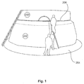
- FIG. 1 In perspective, a first tower segment 200 placed on a foundation is shown, around which a heating device with an outer sub-covering device 202 is shown.
- This outer Operaabdeckvorraum 202 encloses the thus unrecognizable impact area between the tower segment 200 and the foundation 204.
- this outer Operaabdeckvorraum 202 creates a protected space around the tower segment 200 around, which is readily accessible in height and width for adults. To illustrate schematically persons are indicated.
- the outer Operaabdeckvoriques 202 is attached to an upper, circumferential rail 206 on the tower segment 200 and seals substantially against the first tower segment. Such a seal should essentially prevent heat from escaping through convection. Furthermore, a scaffold is disposed below the outer part covering device 202, which is also connected to this circumferential upper rail and substantially determines the outer shape of the outer part covering device 202.
- FIG. 2 shows a portion of a support frame 208 of a still to be completed inner Operaabdeckvorraum.
- Figure 15 shows the interior of the tower segment 200.
- the inner support frame 208 has a circumferential rail, namely inner circulation rail 210.
- the support frame 208 which is provided substantially for clamping a tarpaulin, for holding the support frame 208 connected thereto.
Description
- Die vorliegende Erfindung betrifft eine Wärmvorrichtung zum Wärmen eines ringförmig umlaufenden Stoßbereichs zwischen einem rohrförmigen Turmsegment mit umlaufender Segmentwand und einem Turmfundament einer Windenergieanlage beim Aufbau der Windenergieanlage gemäß dem Oberbegriff des Anspruchs 1. Eine solche Wärmvorrichtung wird z.B. durch
WO2010/147459 offenbart. Verfahren zum Errichten eines Turms einer Windenergieanlage, insbesondere eines Betonturms, sind grundsätzlich bekannt. Zunächst wird ein Betonfundament vorgesehen. Ein Betonturm in Fertigbauweise ist aus mehreren Turmsegmenten zusammengesetzt. Solche Turmsegmente können als rohrförmige und damit zylinderähnliche Elemente, nämlich im Gegensatz zu einem Zylinder mit leicht konischer Form, vorgesehen sein. Bei größeren Turmdurchmessern kommt auch eine Unterteilung in Umfangsrichtung in Betracht, so dass beispielsweise zwei im Querschnitt etwa halbkreisförmige Element oder andere teilkreisförmige Segmente zusammengesetzt werden. - Zunächst werden ein Turmsegment oder mehrere Turmsegmente als erste unterste Turmebene auf dem Fundament aufgesetzt. Es ist wichtig, dass diese erste Ebene sehr sorgfältig ausgerichtet, nämlich ausnivelliert wird. Hierfür wird dieses erste Segment bzw. mehrere Segmente genau ausnivelliert und in dieser ausnivellierten Position zunächst zumindest provisorisch fixiert, um dann zwischen Fundament und diesem untersten Turmsegment bzw. diesen untersten Turmsegmenten eine Ausgleichsmasse einzufügen, die schließlich aushärtet und diese nivellierte Ausrichtung fixiert.
- Problematisch hierbei ist, dass die Aushärtung der Ausgleichsmasse eine gewisse Mindesttemperatur benötigt. Bei niedrigen Außentemperaturen um den Gefrierpunkt kann sich das Aushärten signifikant verlängern oder vollständig scheitern. Dies führt zum einen zu der Gefahr einer schlecht oder unvollständig ausgehärteten Ausgleichsmasse. Andererseits können durch das Abwarten einer verlängerten Aushärtedauer längere Standzeiten für beispielsweise einen zur Installation benötigten Kran resultieren. Ein solcher Kran, der bereits das/die erste(n) Turmsegment(e) auf das Fundament gehoben hat, bleibt für die Dauer des Aushärtens dieser Ausgleichsmasse ungenutzt. Es ergeben sich somit kostspielige zusätzliche Standzeiten des Krans.
- Im Weiteren wird der Turm sukzessive aufgebaut, indem weitere Turmsegmente auf den bis dahin aufgebauten Teilturm aufgesetzt werden. Die hierfür notwendigen Arbeiten entstehen somit zunehmend in höherer Höhe. Im Bereich der obersten Ebene des jeweils fertiggestellten Turmabschnitts wird somit regelmäßig ein Gerüst oder Arbeitsplattform angeordnet, auf dem Arbeiter des Aufbauteams das Aufsetzen eines neuen Turmsegmentes kontrollieren können. Hierbei muss insbesondere kontrolliert werden, dass das jeweilige neue Turmsegment an exakt der richtigen, vorgesehenen Position angeordnet wird. Mittels eines Kranes wird so jedes Turmsegment sukzessive etwa an seinen Platz gehoben und ein Kranführer führt eine Feinpositionierung des betreffenden Turmsegmentes aus. Die genaue Positionierung jedes Turmsegmentes wird dann von den Arbeitern des Aufbauteams auf der besagten Arbeitsplattform manuell, also mit Muskelkraft vorgenommen. Insbesondere muss das betreffende Turmsegment regelmäßig in die korrekte Position gedreht werden. Das Aufbaupersonal hält das so per Hand ausgerichtete Turmsegment in der korrekten Position und der Kranführer senkt das Turmsegment dann langsam ab, während das Aufbauteam dafür sorgt, dass die ausgerichtete Position beibehalten wird. Es ist dabei zu berücksichtigen, dass ein solches Turmsegment etwa 5 bis 120 t wiegen kann. Es muss somit trotz Einsatz großer Muskelkräfte eine sehr feine Positionierung vorgenommen werden.
- Dieses Verfahren zum Aufsetzen eines weiteren Turmsegmentes ist somit kompliziert, zeit- und arbeitsaufwändig und weist eine gewisse Fehleranfälligkeit. Zudem besteht die Gefahr von Verletzungen für die Arbeiter vor Ort, insbesondere die Gefahr von Quetschungen.
- Ist das neue Turmsegment auf dem bis dahin errichteten Turm angeordnet, muss das Turmsegment von einer Traverse, mit der der Kran das Turmsegment gehoben hat, getrennt werden. Hierzu können Tragschlaufen, wie zu Schlaufen geformte Stahlseile an dem Turmsegment befestigt sein. Die Traverse wird dann von diesen Schlaufen gelöst, wie beispielsweise ausgehakt und die Stahlseilschlaufen als solche werden dann manuell von den Arbeitern auf der Arbeitsplattform von dem aufgesetzten Turmsegment entfernt. Auch dies ist aufwändig und erfordert einen recht hohen Personalaufwand einschließlich entsprechender Arbeitsplattform in der Höhe des bis dahin fertiggestellten Turms.
- Ganz allgemein sei auf die Dokumente
US 3,074,564 A ,DE 10 2009 023 538 A1 undDE 20 2010 000 868 U1 verwiesen. - Der vorliegenden Erfindung liegt somit die Aufgabe zugrunde, den Aufbau eines Betonturms einer Windenergieanlage effizienter zu gestalten. Zumindest soll eine alternative Lösung vorgeschlagen werden.
- Erfindungsgemäß wird eine Wärmvorrichtung zum Wärmen eines ringförmig umlaufenden Stoßbereichs zwischen einem rohrförmigen Turmsegment mit umlaufender Segmentwand und einem Turmfundament einer Windenergieanlage beim Aufbau der Windenergieanlage gemäß Anspruch 1 vorgeschlagen. Diese Wärmvorrichtung weist ein oder mehrere Abdeckplanen zum Abdecken des Stoßbereichs auf. Weiterhin weist sie eines oder mehrere ringförmige Traggerüste zum Tragen der bzw. einer der Abdeckplanen auf. Dabei ist das eine oder die mehreren Traggerüste so ausgebildet, dass ausreichend Raum für wenigstens eine erwachsene Person zwischen dem Stoßbereich und der auf das Traggerüst aufgelegten Abdeckplane ist.
- Dieser Wärmvorrichtung liegt die Erkenntnis zugrunde, dass zum Ausrichten eines Turmsegmentes auf einem Turmfundament eine Ausgleichsmasse angeordnet werden kann, die insbesondere bei frostigen Temperaturen, also insbesondere Temperaturen um und insbesondere unter dem Gefrierpunkt schlecht, langsam oder gar nicht aushärtet. Die Errichtung von Türmen von Windenergieanlagen in kalten Gebieten und/oder zu kalten Jahreszeiten ist daher problematisch, kann zumindest zu Verzögerungen in der Errichtung des Windenergieanlagenturmes führen. Unter der Berücksichtigung, dass bereits zum Aufstellen des ersten Turmsegmentes ein entsprechender Kran notwendig ist, bedeutet schon eine Verzögerung des Aufbaus eine Leerlaufzeit des bestellten Krans mit den damit verbundenen Kosten. Durch die Verwendung der Wärmevorrichtung soll somit erreicht werden, trotz tiefen Umgebungstemperaturen die Temperatur in dem Bereich, in dem das Nivellieren mittels Ausgleichsmasse vorgenommen wird, zumindest insoweit zu erhöhen, als dass das Aushärten der Ausgleichsmasse nicht oder nicht wesentlich beeinträchtigt ist.
- Die hierfür vorgeschlagene Wärmvorrichtung schafft im Wesentlichen die Anordnung einer Wärmeabdeckung um besagten zu wärmenden Bereich herum. Hierfür wird eine an den Turm angelehnte oder daran befestigte Haltevorrichtung vorgeschlagen, auf der eine entsprechende Abdeckplane angeordnet wird. Durch die Verwendung des Traggerüstes bzw. der Traggerüste kann die Abdeckung im Grunde so weit von der zu wärmenden Stelle weggehalten werden, dass ausreichend Raum für ein oder mehrere Personen zum Arbeiten entsteht. Die Traggerüste sind hierfür ringförmig ausgestaltet. Unter diese ringförmige Ausgestaltung fällt dabei nicht allein eine ringförmige Form im mathematischen Sinne eines Kreises, sondern auch polygonförmige Konstruktionen, die an die runde Form eines Windenergieanlagenturms bzw. Turmsegments angepasst sind.
- Erfindungsgemäß ist eine äußere Teilabdeckung zum Anordnen außen um das Turmsegment herum vorgesehen, die ihrerseits wenigstens eine Abdeckplane und ein Traggerüst aufweist. So kann es gegebenenfalls ausreichend sein, nur mit einer äußeren Teilabdeckvorrichtung auszukommen, wenn die Außentemperatur nicht zu tief ist und die geschützte Position des Raumes in dem ersten Turmsegment eine ausreichend hohe Temperatur dort gewährleisten kann. Vorzugsweise ist eine innere Teilabdeckvorrichtung zum Anordnen im Inneren des Turmsegmentes vorgesehen, die eine insbesondere eigenständige Konstruktion aus Traggerüst oder Traggerüsten und Abdeckplan oder Abdeckplanen umfasst.
- Vorzugsweise weist das wenigstens eine Traggerüst einen ringförmig umlaufenden oberen Tragabschnitt zum Befestigen an dem Turmsegment auf. Davon ausgehend kann das Traggerüst weiter aufgebaut werden, insbesondere können Abhaltestreben zum Abhalten der Abdeckplane angeordnet werden.
- Eine Abdeckplane kann aus einem wasserdichten Material bestehen, um gleichzeitig auch einen Regenschutz zu bieten. Andererseits ist eine Abdeckplane hierauf nicht beschränkt, sondern es kommen auch luft- und/oder wasserdurchlässige Materialien in Betracht. Eine hohe Isoliereigenschaft dieser Plane kann vorgesehen sein. Je nach Außentemperatur kann eine dünne Plane ausreichen, die im Wesentlichen eine Luftzirkulation und insbesondere das Entweichen warmer Luft durch Konvektion verhindert oder zumindest minimiert.
- Vorzugsweise ist ein Heizmittel, insbesondere ein Heizlüfter vorgesehen. Dieser erwärmt die Luft in dem Raum zwischen dem Stoßbereich und Abdeckplane und die Abdeckplane verhindert im Wesentlichen das Entweichen der so erwärmten Luft. Es ist zu wiederholen, dass ein Erwärmen auf Temperaturen kurz über dem Gefrierpunkt oftmals ausreichen kann, um das Aushärten der Ausgleichsmasse zu ermöglichen.
- Vorzugsweise weist die Abdeckplane eine lichtabsorbierende Oberfläche auf. Hierdurch kann das Sonnenlicht zusätzlich zum Erwärmen herangezogen werden. Je nach Außentemperatur und Sonneneinstrahlung kann eine solche Erwärmung ausreichen, oder ergänzend wird ein Heizmittel wie bspw. ein Heizlüfter verwendet.
- Nachfolgend wird die Erfindung an Hand von Ausführungsbeispielen unter Bezugnahme auf die begleitenden Figuren beispielhaft erläutert.
-
Figur 1 zeigt ein erstes Turmsegment mit einer Wärmvorrichtung in einer perspektivischen Ansicht. -
Figur 2 zeigt einen Teil eines Unterbaus einer Wärmvorrichtung im Inneren eines Turmsegmentes. - In der
Figur 1 ist perspektivisch ein erstes auf einem Fundament aufgesetztes Turmsegment 200 dargestellt, um das herum eine Wärmvorrichtung mit einer äußeren Teilabdeckvorrichtung 202 dargestellt ist. Diese äußere Teilabdeckvorrichtung 202 umschließt den somit nicht erkennbaren Stoßbereich zwischen dem Turmsegment 200 und dem Fundament 204. Dabei schafft diese äußere Teilabdeckvorrichtung 202 einen geschützten Raum um das Turmsegment 200 herum, der in Höhe und Breite für erwachsene Personen ohne weiteres begehbar ist. Zur Veranschaulichung sind schematisch Personen angedeutet. - Die äußere Teilabdeckvorrichtung 202 ist an einer oberen, umlaufenden Schiene 206 an dem Turmsegment 200 befestigt und dichtet im Wesentlichen gegen das erste Turmsegment ab. Eine solche Abdichtung sollte dabei im Wesentlichen verhindern, dass Wärme durch Konvektion entweicht. Weiterhin ist ein Gerüst unterhalb der äußeren Teilabdeckvorrichtung 202 angeordnet, das auch mit dieser umlaufenden oberen Schiene verbunden ist und im Wesentlichen die äußere Form der äußeren Teilabdeckungsvorrichtung 202 bestimmt.
-
Figur 2 zeigt einen Teil eines Traggerüstes 208 einer noch fertig zu stellenden inneren Teilabdeckvorrichtung. Entsprechend zeigt Figur 15 den Innenraum des Turmsegmentes 200. Auch das innere Traggerüst 208 weist eine umlaufende Schiene, nämlich innere Umlaufschiene 210 auf. Auch in der Darstellung der Figur 15 ist eine Person skizziert, um die Größe des Traggerüstes 208 und damit der vorzusehenden inneren Teilabdeckvorrichtung zu veranschaulichen. Im Übrigen ist das Traggerüst 208, das im Wesentlichen zum Abspannen einer Abdeckplane vorgesehen ist, zum Halten des Traggerüstes 208 mit diesem verbunden.
Claims (5)
- Wärmvorrichtung zum Wärmen eines ringförmig umlaufenden Stoßbereichs zwischen einem rohrförmigen Turmsegment (200) mit umlaufender Segmentwand und einem Turmfundament (204) einer Windenergieanlage beim Aufbau der Windenergieanlage, umfassend- eine oder mehrere Abdeckplanen zum Abdecken des Stoßbereichs und- eines oder mehrere ringförmige Traggerüste zum Tragen der bzw. einer der Abdeckplanen,
wobei zwischen dem Stoßbereich und der Abdeckplane ausreichend Raum für wenigstens eine erwachsene Person ist,
gekennzeichnet durch- eine äußere Teilabdeckvorrichtung (202) zum Anordnen außen um das Turmsegment (200) herum,
wobei die Teilabdeckvorrichtung (202) eine der Abdeckplanen und eines der Traggerüste aufweist. - Wärmvorrichtung nach Anspruch 1, wobei- eine inneren Teilabdeckvorrichtung zum Anordnen im Inneren des Turmsegmentes vorgesehen ist, die eine der Abdeckplanen und eines der Traggerüste aufweist.
- Wärmvorrichtung nach Anspruch 1 oder 2, dadurch gekennzeichnet, dass das bzw. jedes Traggerüst einen ringförmig umlaufenden oberen Tragabschnitt zum Befestigen an dem Turmsegment aufweist.
- Wärmvorrichtung nach einem der Ansprüche 1 bis 3, umfassend wenigstens ein Heizmittel, insbesondere Heizlüfter zum Erwärmen der Luft in dem Raum zwischen dem Stoßbereich und der Abdeckplane.
- Verfahren zum Errichten eines Turms einer Windenergieanlage umfassend die Schritte:- Anordnen eines ersten Turmsegmentes auf einem Fundament, und- Anordnen einer Wärmvorrichtung nach einem der Ansprüche 1 bis 4 am Turmsegment und Abdecken eines ringförmig umlaufenden Stoßbereichs zwischen dem Turmsegment und dem Turmfundament.
Priority Applications (3)
| Application Number | Priority Date | Filing Date | Title |
|---|---|---|---|
| SI201230805A SI2805909T1 (sl) | 2011-01-26 | 2012-01-18 | Grelna naprava |
| RS20160924A RS55347B1 (sr) | 2011-01-26 | 2012-01-18 | Uređaj za zagrevanje |
| HRP20161445TT HRP20161445T1 (hr) | 2011-01-26 | 2016-11-02 | Uređaj za zagrijavanje |
Applications Claiming Priority (2)
| Application Number | Priority Date | Filing Date | Title |
|---|---|---|---|
| DE102011003164A DE102011003164A1 (de) | 2011-01-26 | 2011-01-26 | Verfahren und Vorrichtung zum Errichten eines Turms einer Windenergieanlage |
| EP12700685.6A EP2556008B1 (de) | 2011-01-26 | 2012-01-18 | Vorrichtung und verfahren zum errichten eines turms einer windenergieanlage |
Related Parent Applications (2)
| Application Number | Title | Priority Date | Filing Date |
|---|---|---|---|
| EP12700685.6A Division-Into EP2556008B1 (de) | 2011-01-26 | 2012-01-18 | Vorrichtung und verfahren zum errichten eines turms einer windenergieanlage |
| EP12700685.6A Division EP2556008B1 (de) | 2011-01-26 | 2012-01-18 | Vorrichtung und verfahren zum errichten eines turms einer windenergieanlage |
Publications (2)
| Publication Number | Publication Date |
|---|---|
| EP2805909A1 EP2805909A1 (de) | 2014-11-26 |
| EP2805909B1 true EP2805909B1 (de) | 2016-10-12 |
Family
ID=45509505
Family Applications (4)
| Application Number | Title | Priority Date | Filing Date |
|---|---|---|---|
| EP14180212.4A Active EP2803616B1 (de) | 2011-01-26 | 2012-01-18 | Arbeitsbühnenvorrichtung zum Arbeiten in verändlicher Höhe und Verfahren dafür |
| EP14180218.1A Active EP2805909B1 (de) | 2011-01-26 | 2012-01-18 | Wärmevorrichtung |
| EP12700685.6A Active EP2556008B1 (de) | 2011-01-26 | 2012-01-18 | Vorrichtung und verfahren zum errichten eines turms einer windenergieanlage |
| EP14180214.0A Active EP2803617B1 (de) | 2011-01-26 | 2012-01-18 | Verfahren zum Errichten eines Turms einer Windenergieanlage |
Family Applications Before (1)
| Application Number | Title | Priority Date | Filing Date |
|---|---|---|---|
| EP14180212.4A Active EP2803616B1 (de) | 2011-01-26 | 2012-01-18 | Arbeitsbühnenvorrichtung zum Arbeiten in verändlicher Höhe und Verfahren dafür |
Family Applications After (2)
| Application Number | Title | Priority Date | Filing Date |
|---|---|---|---|
| EP12700685.6A Active EP2556008B1 (de) | 2011-01-26 | 2012-01-18 | Vorrichtung und verfahren zum errichten eines turms einer windenergieanlage |
| EP14180214.0A Active EP2803617B1 (de) | 2011-01-26 | 2012-01-18 | Verfahren zum Errichten eines Turms einer Windenergieanlage |
Country Status (25)
| Country | Link |
|---|---|
| US (1) | US9534416B2 (de) |
| EP (4) | EP2803616B1 (de) |
| JP (3) | JP5860902B2 (de) |
| KR (3) | KR20150090266A (de) |
| CN (3) | CN105035939B (de) |
| AR (1) | AR085029A1 (de) |
| AU (1) | AU2012210698B2 (de) |
| BR (1) | BR112013018604A2 (de) |
| CA (1) | CA2823982C (de) |
| CL (1) | CL2013002121A1 (de) |
| CY (2) | CY1116401T1 (de) |
| DE (1) | DE102011003164A1 (de) |
| DK (4) | DK2803616T3 (de) |
| ES (3) | ES2658437T3 (de) |
| HR (2) | HRP20150718T1 (de) |
| HU (2) | HUE030304T2 (de) |
| LT (1) | LT2805909T (de) |
| MX (1) | MX336620B (de) |
| PL (2) | PL2556008T3 (de) |
| PT (3) | PT2805909T (de) |
| RS (2) | RS54062B1 (de) |
| SI (2) | SI2805909T1 (de) |
| TW (1) | TWI480453B (de) |
| WO (1) | WO2012101023A2 (de) |
| ZA (1) | ZA201304951B (de) |
Families Citing this family (41)
| Publication number | Priority date | Publication date | Assignee | Title |
|---|---|---|---|---|
| WO2014073063A1 (ja) * | 2012-11-08 | 2014-05-15 | ベステラ株式会社 | 集合形煙突解体用足場装置及びその装置を用いた集合形煙突の解体方法 |
| DE102012221453A1 (de) * | 2012-11-23 | 2014-05-28 | Wobben Properties Gmbh | Greifeinrichtung zum Handhaben von Bewehrungskörben für Turmsegmente einer Windenergieanlage |
| DK2824057T3 (en) | 2013-07-11 | 2017-09-11 | Siemens Ag | Lifting of a tower segment |
| DK2826742T3 (da) * | 2013-07-17 | 2019-07-22 | Aip Asp | Elevator system |
| CN103939298B (zh) * | 2014-04-01 | 2016-04-13 | 北京金风科创风电设备有限公司 | 用于混凝土塔架拼装的结构 |
| CN104213714B (zh) * | 2014-08-27 | 2016-03-09 | 中国建筑第二工程局有限公司 | 一种超大型屋架的提升吊点加固结构及吊装施工方法 |
| US20170241153A1 (en) * | 2014-10-06 | 2017-08-24 | Vestas Wind Systems A/S | Hinged tower segments and transport method |
| CN104631839B (zh) * | 2015-01-29 | 2016-08-24 | 浙江勤业建工集团有限公司 | 超高超重大跨度空中连廊整体提升施工方法 |
| CN104803308B (zh) * | 2015-04-28 | 2017-01-18 | 中国水利水电第八工程局有限公司 | 用于钢管加劲环拼装的吊装装置 |
| CN105119189A (zh) * | 2015-08-27 | 2015-12-02 | 国家电网公司 | 一种超长瓷片式绝缘子串吊装架 |
| CN105119190A (zh) * | 2015-08-27 | 2015-12-02 | 国家电网公司 | 一种自锁式瓷片式绝缘子吊装架 |
| WO2017039975A1 (en) * | 2015-08-31 | 2017-03-09 | Siemens Energy, Inc. | System and method for installing a tensioning tendon in a wind turbine tower |
| DE102016200160A1 (de) * | 2016-01-08 | 2017-07-13 | Wobben Properties Gmbh | Hebevorrichtung zum Heben einer Komponente einer Windenergieanlage und Verfahren zum Montieren von Komponenten einer Windenergieanlage |
| GB2551481A (en) * | 2016-06-08 | 2017-12-27 | John Reed Patrick | A sheeting system |
| CN106337785B (zh) * | 2016-09-29 | 2019-01-25 | 中车株洲电力机车研究所有限公司 | 风力发电机组风轮内葫芦辅助拆装工具及方法 |
| WO2018086837A1 (en) * | 2016-11-11 | 2018-05-17 | Siemens Aktiengesellschaft | Transport assembly |
| US10704535B2 (en) | 2016-11-23 | 2020-07-07 | Mhi Vestas Offshore Wind A/S | Method and assembly for aligning wind turbine structural parts |
| CN106640558B (zh) * | 2016-12-30 | 2019-04-12 | 北京金风科创风电设备有限公司 | 风力涡轮机的变桨轴承、叶片、叶轮及连接方法 |
| CN106903014A (zh) * | 2017-02-28 | 2017-06-30 | 李金平 | 一种喷涂行业用定心转盘 |
| CN106744252B (zh) * | 2017-03-27 | 2018-09-21 | 江苏中车电机有限公司 | 用于mw级直驱永磁风力发电机转子吊运工装及使用方法 |
| CN107152021B (zh) * | 2017-06-06 | 2023-03-28 | 中国石油天然气集团公司 | 一种u形管桩护甲安装工具 |
| DK3450752T3 (da) | 2017-09-04 | 2020-08-10 | Siemens Gamesa Renewable Energy As | Vindmølle med en adgangsanordning til en nacelle |
| CN107953975B (zh) * | 2017-11-22 | 2023-06-02 | 自然资源部第二海洋研究所 | 船用机械臂止荡机构 |
| CN109058052B (zh) * | 2018-08-29 | 2020-08-21 | 江苏仕沃精密机械科技有限公司 | 新能源风力发电设备的集成式固定安装架 |
| CN109809287B (zh) * | 2019-03-18 | 2020-05-12 | 哈尔滨电机厂有限责任公司 | 一种用于周向装配的对称起吊装置的使用方法 |
| CN110565934A (zh) * | 2019-07-26 | 2019-12-13 | 江苏兴厦建设工程集团有限公司 | 一种建筑外墙悬吊式人货电梯施工平台及其安装方法 |
| DE102019122021A1 (de) * | 2019-08-15 | 2021-02-18 | Wobben Properties Gmbh | Montagetraverse und Verfahren zum Einziehen von kabelförmigen Elementen, insbesondere von Spanngliedern, entlang eines Turms einer Windenergieanlage |
| JP6798721B1 (ja) * | 2019-09-30 | 2020-12-09 | 村田油圧機械株式会社 | 連絡ブリッジ用の水平回動アクチュエータ |
| JP6798720B1 (ja) * | 2019-09-30 | 2020-12-09 | 村田油圧機械株式会社 | 連絡ブリッジ用の伸縮アクチュエータ |
| JP6882795B2 (ja) * | 2019-09-30 | 2021-06-02 | 村田油圧機械株式会社 | 連絡ブリッジ |
| CN111039152B (zh) * | 2019-12-31 | 2021-01-26 | 烟台腾泰环保建材有限公司 | 一种混凝土预制构件 |
| CN111980865B (zh) * | 2020-07-29 | 2021-11-12 | 上海市机电设计研究院有限公司 | 减小预制混凝土筒片错动的筒节吊装方法 |
| CN111997432B (zh) * | 2020-07-29 | 2021-12-14 | 上海市机电设计研究院有限公司 | 预制混凝土塔筒的施工平台提升装置及方法 |
| CN113023540B (zh) * | 2021-03-15 | 2022-03-01 | 合肥中科离子医学技术装备有限公司 | 一种用于回旋加速器整机的吊装运输一体式装置 |
| CN113090037A (zh) * | 2021-04-01 | 2021-07-09 | 浙江明康工程咨询有限公司 | 一种卸料平台的预警方法及系统 |
| CN113503047A (zh) * | 2021-07-31 | 2021-10-15 | 中冶(上海)钢结构科技有限公司 | 钢结构提升过程中牵引调整高空位置偏移的方法 |
| CN113756647B (zh) * | 2021-09-04 | 2022-11-08 | 中铁十五局集团有限公司 | 一种线路铁塔分段结构的施工方法及其装置 |
| CN113944313B (zh) * | 2021-11-03 | 2023-04-11 | 上海建工五建集团有限公司 | 悬挑型钢顶撑限位装置、悬挑钢平台及其施工方法 |
| CN114108996B (zh) * | 2021-11-26 | 2023-06-06 | 中煤西安设计工程有限责任公司 | 一种无楼板砖砌填充墙的施工装置及方法 |
| CN115285854B (zh) * | 2022-09-28 | 2022-12-02 | 中国能源建设集团山西电力建设有限公司 | 大型圆柱形罐体的低空拼装分节抬升的装配方法 |
| CN117703164B (zh) * | 2024-02-05 | 2024-04-09 | 辽宁省送变电工程有限公司 | 高低铁塔塔腿段组立自动提升装置 |
Family Cites Families (52)
| Publication number | Priority date | Publication date | Assignee | Title |
|---|---|---|---|---|
| US3074564A (en) * | 1961-03-01 | 1963-01-22 | Chicago Bridge & Iron Co | Mast extension jib |
| DE1251803B (de) * | 1963-12-05 | 1967-10-12 | Siemens Aktiengesellschaft, Berlin und München München | Verfah ren und Einrichtung zum Regenerieren von phasenmodulierten Impulsfolgen |
| CH508507A (de) * | 1969-05-28 | 1971-06-15 | Von Roll Ag | Zahnstange für eine Fahrschiene für Hängebahnen |
| JPS5830882Y2 (ja) * | 1978-06-21 | 1983-07-08 | 住友金属工業株式会社 | 大型コンクリ−ト構造体用吊筋 |
| SU958296A1 (ru) | 1980-06-12 | 1982-09-15 | Республиканское Проектно-Технологическое Производственное Объединение "Росоргтехстрой" | Захват-кантователь дл изделий с цапфами |
| DE8424193U1 (de) * | 1984-08-16 | 1985-12-12 | Ernst Peiniger GmbH Unternehmen für Bautenschutz, 4300 Essen | Arbeitsplatzverschlag |
| EP0688922B1 (de) * | 1994-06-23 | 1998-04-22 | HALFEN GmbH & CO. Kommanditgesellschaft | Transportanker, insbesondere für Betonfertigteile und in den Transportanker einschraubbarer Lastaufnehmer |
| TW253924B (en) | 1994-09-14 | 1995-08-11 | Nippon Kotetsu Kokusai Kk | Elevatable work facility |
| JPH08303441A (ja) * | 1995-05-01 | 1996-11-19 | Aioi Seiki Kk | ガイド兼ロック機構付きコネクタ装置 |
| DE69910404T2 (de) * | 1998-02-04 | 2004-06-24 | Heston, Stephen L., West Linn | Palettiervorrichtung |
| DE19857744B4 (de) * | 1998-12-15 | 2007-05-16 | Schuler Pressen Gmbh & Co | Presse mit Stempelverstellung, insbesondere zur Massivumformung |
| JP2000283019A (ja) * | 1999-03-31 | 2000-10-10 | Pc Bridge Co Ltd | コンクリート製風車支持タワー及びその構築方法 |
| DE10025074B4 (de) | 2000-05-20 | 2006-11-09 | Hailo-Werk Rudolf Loh Gmbh & Co. Kg | Einrichtung zum Befördern von Personen |
| US6782667B2 (en) | 2000-12-05 | 2004-08-31 | Z-Tek, Llc | Tilt-up and telescopic support tower for large structures |
| DE10104351A1 (de) * | 2001-02-01 | 2002-08-22 | Ingenieurgesellschaft Foerder | Aufzug mit auf der Aufzugskabine mitfahrender Antriebseinheit und Steuereinheit |
| US6625940B2 (en) * | 2001-02-02 | 2003-09-30 | Wallace D. Sanger | Concrete building module with module lifting means and method |
| DE10160022A1 (de) * | 2001-12-06 | 2003-06-18 | Gen Electric | Verfahren zum Herstellen eines Turms einer Windkraftanlage, mit diesem Verfahren hergestellter Turm und Bauelemente zur Herstellung eines Turms |
| DE10163538B4 (de) * | 2001-12-21 | 2004-09-30 | Norbert Plambeck | Vorrichtung und Verfahren zum Transport und zur Errichtung von Offshore-Windenergieanlagen |
| GB2394498B (en) * | 2002-10-23 | 2006-08-09 | Engineering Business Ltd | Mounting of offshore structures |
| JP2004156478A (ja) * | 2002-11-05 | 2004-06-03 | Kashiwabara Painting Works Co Ltd | 独立型塔体構造物の作業用足場装置及び作業用足場設置工法 |
| CN100445552C (zh) * | 2003-12-30 | 2008-12-24 | Pp能源有限责任公司 | 用于抵达位于地面上方的结构的设备 |
| GB0500619D0 (en) | 2005-01-13 | 2005-02-23 | Severfield Rowen Plc | Improvements relating to construction |
| CN101614083B (zh) * | 2005-01-19 | 2014-09-24 | Iti苏格兰有限公司 | 夹具、自移式爬升装置和联接夹具与管形件的方法 |
| US20060213145A1 (en) * | 2005-03-22 | 2006-09-28 | Haller Mark E | Lattice-skin hybrid tower |
| JP2007046292A (ja) * | 2005-08-09 | 2007-02-22 | Oriental Construction Co Ltd | タワー構築用ブロック |
| JP4701047B2 (ja) * | 2005-09-07 | 2011-06-15 | 株式会社竹中工務店 | 風力発電タワーの構築方法 |
| TWM296876U (en) | 2006-03-07 | 2006-09-01 | Runhorn Pretech Eng Co Ltd | Wall structure preset hanging point |
| CN101484698A (zh) * | 2006-06-29 | 2009-07-15 | 维斯塔斯风力系统有限公司 | 用于风轮机的塔体构造 |
| ATE491665T1 (de) * | 2006-06-30 | 2011-01-15 | Vestas Wind Sys As | Hubeinrichtung zur handhabung einer windturbinenkomponente und verfahren zur handhabung einer windturbinenkomponente |
| CN101535582B (zh) * | 2006-10-02 | 2013-03-27 | 通用风能有限责任公司 | 用于构建和包覆风力涡轮机塔架的提升系统及装置 |
| KR20090011746A (ko) * | 2007-07-27 | 2009-02-02 | 주식회사 피엔에이치 | 자동 개방형 샤클 조립체의 안전장치 |
| AU2008221636A1 (en) * | 2007-10-11 | 2009-04-30 | General Electric Company | Wind tower and method of assembling the same |
| WO2009101697A1 (ja) * | 2008-02-15 | 2009-08-20 | Sakuraigiken Co., Ltd. | 風力発電設備の風車羽根のメンテナンス工法及びメンテナンス装置 |
| US20090223163A1 (en) | 2008-03-10 | 2009-09-10 | Shu Ching Quek | Wind Turbine Tower Including An Induction Brazed Joint And A Method Of Fabricating The Wind Turbine Tower |
| JP5069171B2 (ja) * | 2008-05-22 | 2012-11-07 | 鹿島建設株式会社 | 洋上風力発電の基礎と上部工の接合部構造および上部工の据付方法 |
| TW201016961A (en) | 2008-10-16 | 2010-05-01 | Mitsubishi Heavy Ind Ltd | Wind-powered electric generator |
| EP2256338B1 (de) * | 2008-11-03 | 2014-01-01 | Siemens Aktiengesellschaft | Fundament, insbesondere für eine Windturbine, und Windturbine |
| EP2192245B1 (de) * | 2008-11-27 | 2012-05-30 | Vestas Wind Systems A/S | Turm für eine Windturbine und Verfahren zu dessen Herstellung |
| CN101481069B (zh) * | 2008-12-10 | 2012-09-05 | 三一电气有限责任公司 | 一种攀爬系统和攀爬起吊系统 |
| SE534035C2 (sv) * | 2009-04-08 | 2011-04-12 | Ncc Construction Sverige Ab | Förfarande för byggande av vindkraftverk |
| DE102009061027A1 (de) * | 2009-04-19 | 2010-10-28 | Timber Tower Gmbh | Turm für eine Windkraftanlage |
| CA2698710A1 (en) * | 2009-05-05 | 2010-11-05 | Fws Technologies Holdings Ltd. | Slip formed concrete wind turbine tower |
| DE102009023538A1 (de) * | 2009-05-30 | 2010-12-09 | Kai Berkenbrink | Turm einer Windkraftanlage, Windkraftanlage sowie Verfahren zum Anheben von Komponenten einer Windkraftanlage |
| NL1037052C2 (en) * | 2009-06-19 | 2010-12-21 | Darwind Holding B V | A method of finishing a tower section of a wind turbine, a finished tower section of a wind turbine, and a method of transporting a tower section of a wind turbine. |
| BR112012000808A2 (pt) | 2009-07-13 | 2016-02-23 | Vsl Int Ag | conjunto de torre telescópica e método |
| DE202010000868U1 (de) * | 2009-07-20 | 2010-12-02 | Wader-Wittis Gmbh | Vorrichtung zum Transport und zur Montage von Windkraftanlagen |
| CN102471039A (zh) * | 2009-07-24 | 2012-05-23 | 西门子公司 | 提升配件 |
| US8596700B2 (en) * | 2009-08-14 | 2013-12-03 | Mjt Holdings, Llc | Tower erection lift kit tools |
| DE102009051425A1 (de) * | 2009-10-30 | 2011-05-05 | Voith Patent Gmbh | Strömungskraftwerk und Verfahren für dessen Erstellung |
| US8544924B2 (en) * | 2009-11-06 | 2013-10-01 | Engineered Lifting Technologies, Inc. | Lifting assembly |
| US8434799B2 (en) * | 2010-06-03 | 2013-05-07 | Robert J. Reger | Synthetic fiber sling and roller system for carrying and positioning a load |
| EP2402278B1 (de) * | 2010-06-29 | 2012-11-21 | Siemens Aktiengesellschaft | Anordnung zum Anheben eines Turmwandabschnitts einer Windturbine und Verfahren zum Anheben einer Turmwandabschnitts einer Windturbine |
-
2011
- 2011-01-26 DE DE102011003164A patent/DE102011003164A1/de not_active Withdrawn
-
2012
- 2012-01-18 AU AU2012210698A patent/AU2012210698B2/en not_active Ceased
- 2012-01-18 DK DK14180212.4T patent/DK2803616T3/da active
- 2012-01-18 LT LTEP14180218.1T patent/LT2805909T/lt unknown
- 2012-01-18 RS RS20150408A patent/RS54062B1/en unknown
- 2012-01-18 PT PT141802181T patent/PT2805909T/pt unknown
- 2012-01-18 WO PCT/EP2012/050729 patent/WO2012101023A2/de active Application Filing
- 2012-01-18 KR KR1020157019627A patent/KR20150090266A/ko not_active Application Discontinuation
- 2012-01-18 DK DK14180214.0T patent/DK2803617T3/en active
- 2012-01-18 CN CN201510309176.XA patent/CN105035939B/zh not_active Expired - Fee Related
- 2012-01-18 MX MX2013008532A patent/MX336620B/es unknown
- 2012-01-18 EP EP14180212.4A patent/EP2803616B1/de active Active
- 2012-01-18 CA CA2823982A patent/CA2823982C/en not_active Expired - Fee Related
- 2012-01-18 RS RS20160924A patent/RS55347B1/sr unknown
- 2012-01-18 ES ES14180214.0T patent/ES2658437T3/es active Active
- 2012-01-18 CN CN201280006757.0A patent/CN103476696B/zh active Active
- 2012-01-18 KR KR1020157019628A patent/KR20150090267A/ko not_active Application Discontinuation
- 2012-01-18 EP EP14180218.1A patent/EP2805909B1/de active Active
- 2012-01-18 BR BR112013018604-6A patent/BR112013018604A2/pt not_active Application Discontinuation
- 2012-01-18 CN CN201510309673.XA patent/CN105020228B/zh not_active Expired - Fee Related
- 2012-01-18 PT PT141802140T patent/PT2803617T/pt unknown
- 2012-01-18 SI SI201230805A patent/SI2805909T1/sl unknown
- 2012-01-18 PT PT127006856T patent/PT2556008E/pt unknown
- 2012-01-18 ES ES14180218.1T patent/ES2611830T3/es active Active
- 2012-01-18 JP JP2013550827A patent/JP5860902B2/ja active Active
- 2012-01-18 US US13/981,713 patent/US9534416B2/en active Active
- 2012-01-18 HU HUE14180218A patent/HUE030304T2/en unknown
- 2012-01-18 PL PL12700685T patent/PL2556008T3/pl unknown
- 2012-01-18 EP EP12700685.6A patent/EP2556008B1/de active Active
- 2012-01-18 DK DK12700685.6T patent/DK2556008T3/en active
- 2012-01-18 HU HUE12700685A patent/HUE026787T2/en unknown
- 2012-01-18 ES ES12700685.6T patent/ES2541637T3/es active Active
- 2012-01-18 PL PL14180218T patent/PL2805909T3/pl unknown
- 2012-01-18 KR KR1020137022160A patent/KR101665169B1/ko active IP Right Grant
- 2012-01-18 EP EP14180214.0A patent/EP2803617B1/de active Active
- 2012-01-18 DK DK14180218.1T patent/DK2805909T3/en active
- 2012-01-18 SI SI201230211T patent/SI2556008T1/sl unknown
- 2012-01-19 TW TW101102283A patent/TWI480453B/zh not_active IP Right Cessation
- 2012-01-25 AR ARP120100242A patent/AR085029A1/es active IP Right Grant
-
2013
- 2013-07-03 ZA ZA2013/04951A patent/ZA201304951B/en unknown
- 2013-07-24 CL CL2013002121A patent/CL2013002121A1/es unknown
-
2014
- 2014-10-31 JP JP2014223324A patent/JP6038098B2/ja active Active
- 2014-10-31 JP JP2014223332A patent/JP6282572B2/ja active Active
-
2015
- 2015-06-12 CY CY20151100516T patent/CY1116401T1/el unknown
- 2015-07-02 HR HRP20150718TT patent/HRP20150718T1/hr unknown
-
2016
- 2016-11-02 HR HRP20161445TT patent/HRP20161445T1/hr unknown
- 2016-12-09 CY CY20161101275T patent/CY1118427T1/el unknown
Also Published As
Similar Documents
| Publication | Publication Date | Title |
|---|---|---|
| EP2805909B1 (de) | Wärmevorrichtung | |
| AT513261B1 (de) | Verfahren zur Herstellung eines Turmbauwerks aus Stahlbeton | |
| DE202010017898U1 (de) | Turm für eine Windkraftanlage | |
| DE10321647A1 (de) | Fundament für eine Windenergieanlage | |
| EP1619727A2 (de) | Vorrichtung zum Befestigen von Funktionsgruppen auf Flachdächern, insbesondere von Solarmodulen auf Industriehallen | |
| EP3042011B1 (de) | Verfahren zur montage von turmeinbauten | |
| DE102016121273A1 (de) | Rotorblattbefahranlage | |
| DE202009002054U1 (de) | Wetter- und Montageschutzvorrichtung für Rotorblätter | |
| EP3047083B1 (de) | Variables schutzdach | |
| DE102010008897B4 (de) | Verfahren zur Errichtung eines Behälters für eine Biogasanlage | |
| EP2712985B1 (de) | Verfahren zum Erstellen eines Turms, insbesondere eines Turms für eine Windkraftanlage | |
| DE102010014787B4 (de) | Solarthermische Anlage | |
| DE102012208107A1 (de) | Vorrichtung zur Überdachung von Fahrzeugstell- bzw. -parkplätzen | |
| DE102017002525B4 (de) | Arbeitsbühne für insbesondere den Aufbau von Turmsegmenten und Türmen von beispielsweise Windkraftanlagen | |
| EP1959068B1 (de) | Vorrichtung zu Sanierung von Flachdächern | |
| DE102013002549A1 (de) | Turm für eine Windkraftanlage | |
| EP2306118A2 (de) | Vorrichtung zur Montage von Solarmodulen auf Flachdächern | |
| DE102010012408A1 (de) | Trägeranordnung für eine Windenergieanlage, Windenergieanlage mit einer Trägeranordnung und Verfahren zum Errichten einer Windenergieanlage | |
| EP3219879B1 (de) | Verfahren zum aufstellen eines windenergieanlagen-turms sowie entsprechende windenergieanlage | |
| CH687553A5 (de) | Kugelhaus. | |
| DE202013104660U1 (de) | Sonnensegel | |
| DE2115775C3 (de) | Pneumatische Bauwerkskonstruktion | |
| DE2412830A1 (de) | Befestigung und feuchtigkeitsschutz von waermedaemmstoffen | |
| DE202014101245U1 (de) | Schutzvorrichtung zum Abdecken einer Öffnung eines Turmes einer Windkraftanlage oder eines ähnlichen Bauwerks | |
| EP2734688A2 (de) | Tribünendach |
Legal Events
| Date | Code | Title | Description |
|---|---|---|---|
| PUAI | Public reference made under article 153(3) epc to a published international application that has entered the european phase |
Free format text: ORIGINAL CODE: 0009012 |
|
| 17P | Request for examination filed |
Effective date: 20140807 |
|
| AC | Divisional application: reference to earlier application |
Ref document number: 2556008 Country of ref document: EP Kind code of ref document: P |
|
| AK | Designated contracting states |
Kind code of ref document: A1 Designated state(s): AL AT BE BG CH CY CZ DE DK EE ES FI FR GB GR HR HU IE IS IT LI LT LU LV MC MK MT NL NO PL PT RO RS SE SI SK SM TR |
|
| R17P | Request for examination filed (corrected) |
Effective date: 20150526 |
|
| RBV | Designated contracting states (corrected) |
Designated state(s): AL AT BE BG CH CY CZ DE DK EE ES FI FR GB GR HR HU IE IS IT LI LT LU LV MC MK MT NL NO PL PT RO RS SE SI SK SM TR |
|
| RIC1 | Information provided on ipc code assigned before grant |
Ipc: B66C 1/10 20060101ALI20151026BHEP Ipc: B66B 19/00 20060101ALI20151026BHEP Ipc: F02C 6/18 20060101ALI20151026BHEP Ipc: B66B 9/187 20060101ALI20151026BHEP Ipc: E04G 21/14 20060101ALI20151026BHEP Ipc: F03D 11/04 20060101AFI20151026BHEP Ipc: F03D 1/00 20060101ALI20151026BHEP |
|
| GRAP | Despatch of communication of intention to grant a patent |
Free format text: ORIGINAL CODE: EPIDOSNIGR1 |
|
| RAP1 | Party data changed (applicant data changed or rights of an application transferred) |
Owner name: WOBBEN PROPERTIES GMBH |
|
| INTG | Intention to grant announced |
Effective date: 20151221 |
|
| REG | Reference to a national code |
Ref country code: DE Ref legal event code: R079 Ref document number: 502012008548 Country of ref document: DE Free format text: PREVIOUS MAIN CLASS: B66C0001100000 Ipc: F03D0001000000 |
|
| GRAP | Despatch of communication of intention to grant a patent |
Free format text: ORIGINAL CODE: EPIDOSNIGR1 |
|
| INTG | Intention to grant announced |
Effective date: 20160525 |
|
| RIC1 | Information provided on ipc code assigned before grant |
Ipc: E04G 3/28 20060101ALI20160517BHEP Ipc: E04G 21/14 20060101ALI20160517BHEP Ipc: B66B 19/00 20060101ALI20160517BHEP Ipc: E04B 1/04 20060101ALI20160517BHEP Ipc: E04H 12/34 20060101ALI20160517BHEP Ipc: F24H 3/02 20060101ALI20160517BHEP Ipc: E04H 12/12 20060101ALI20160517BHEP Ipc: B66C 1/10 20060101ALI20160517BHEP Ipc: E04G 5/00 20060101ALI20160517BHEP Ipc: F03D 13/20 20160101ALI20160517BHEP Ipc: F16B 1/00 20060101ALI20160517BHEP Ipc: F03D 1/00 20060101AFI20160517BHEP Ipc: B66B 9/187 20060101ALI20160517BHEP Ipc: F02C 6/18 20060101ALI20160517BHEP Ipc: F16B 35/06 20060101ALI20160517BHEP |
|
| GRAS | Grant fee paid |
Free format text: ORIGINAL CODE: EPIDOSNIGR3 |
|
| GRAA | (expected) grant |
Free format text: ORIGINAL CODE: 0009210 |
|
| AC | Divisional application: reference to earlier application |
Ref document number: 2556008 Country of ref document: EP Kind code of ref document: P |
|
| AK | Designated contracting states |
Kind code of ref document: B1 Designated state(s): AL AT BE BG CH CY CZ DE DK EE ES FI FR GB GR HR HU IE IS IT LI LT LU LV MC MK MT NL NO PL PT RO RS SE SI SK SM TR |
|
| REG | Reference to a national code |
Ref country code: GB Ref legal event code: FG4D Free format text: NOT ENGLISH |
|
| REG | Reference to a national code |
Ref country code: CH Ref legal event code: NV Representative=s name: WEINMANN ZIMMERLI, CH Ref country code: CH Ref legal event code: EP |
|
| REG | Reference to a national code |
Ref country code: AT Ref legal event code: REF Ref document number: 836761 Country of ref document: AT Kind code of ref document: T Effective date: 20161015 |
|
| REG | Reference to a national code |
Ref country code: HR Ref legal event code: TUEP Ref document number: P20161445 Country of ref document: HR Ref country code: IE Ref legal event code: FG4D Free format text: LANGUAGE OF EP DOCUMENT: GERMAN |
|
| REG | Reference to a national code |
Ref country code: DE Ref legal event code: R096 Ref document number: 502012008548 Country of ref document: DE |
|
| REG | Reference to a national code |
Ref country code: HR Ref legal event code: T1PR Ref document number: P20161445 Country of ref document: HR |
|
| REG | Reference to a national code |
Ref country code: RO Ref legal event code: EPE |
|
| REG | Reference to a national code |
Ref country code: NL Ref legal event code: FP |
|
| REG | Reference to a national code |
Ref country code: PT Ref legal event code: SC4A Ref document number: 2805909 Country of ref document: PT Date of ref document: 20170112 Kind code of ref document: T Free format text: AVAILABILITY OF NATIONAL TRANSLATION Effective date: 20170103 |
|
| REG | Reference to a national code |
Ref country code: DK Ref legal event code: T3 Effective date: 20170116 |
|
| REG | Reference to a national code |
Ref country code: FR Ref legal event code: PLFP Year of fee payment: 6 |
|
| REG | Reference to a national code |
Ref country code: SE Ref legal event code: TRGR |
|
| REG | Reference to a national code |
Ref country code: EE Ref legal event code: FG4A Ref document number: E013041 Country of ref document: EE Effective date: 20161205 |
|
| REG | Reference to a national code |
Ref country code: NO Ref legal event code: T2 Effective date: 20161012 |
|
| REG | Reference to a national code |
Ref country code: HU Ref legal event code: AG4A Ref document number: E030304 Country of ref document: HU |
|
| REG | Reference to a national code |
Ref country code: ES Ref legal event code: FG2A Ref document number: 2611830 Country of ref document: ES Kind code of ref document: T3 Effective date: 20170510 |
|
| REG | Reference to a national code |
Ref country code: SK Ref legal event code: T3 Ref document number: E 23085 Country of ref document: SK |
|
| REG | Reference to a national code |
Ref country code: GR Ref legal event code: EP Ref document number: 20160403061 Country of ref document: GR Effective date: 20170410 |
|
| REG | Reference to a national code |
Ref country code: DE Ref legal event code: R097 Ref document number: 502012008548 Country of ref document: DE |
|
| PLBE | No opposition filed within time limit |
Free format text: ORIGINAL CODE: 0009261 |
|
| STAA | Information on the status of an ep patent application or granted ep patent |
Free format text: STATUS: NO OPPOSITION FILED WITHIN TIME LIMIT |
|
| PG25 | Lapsed in a contracting state [announced via postgrant information from national office to epo] |
Ref country code: SM Free format text: LAPSE BECAUSE OF FAILURE TO SUBMIT A TRANSLATION OF THE DESCRIPTION OR TO PAY THE FEE WITHIN THE PRESCRIBED TIME-LIMIT Effective date: 20161012 |
|
| 26N | No opposition filed |
Effective date: 20170713 |
|
| PG25 | Lapsed in a contracting state [announced via postgrant information from national office to epo] |
Ref country code: MC Free format text: LAPSE BECAUSE OF FAILURE TO SUBMIT A TRANSLATION OF THE DESCRIPTION OR TO PAY THE FEE WITHIN THE PRESCRIBED TIME-LIMIT Effective date: 20161012 |
|
| PG25 | Lapsed in a contracting state [announced via postgrant information from national office to epo] |
Ref country code: LU Free format text: LAPSE BECAUSE OF NON-PAYMENT OF DUE FEES Effective date: 20170118 |
|
| REG | Reference to a national code |
Ref country code: FR Ref legal event code: PLFP Year of fee payment: 7 |
|
| PG25 | Lapsed in a contracting state [announced via postgrant information from national office to epo] |
Ref country code: MT Free format text: LAPSE BECAUSE OF FAILURE TO SUBMIT A TRANSLATION OF THE DESCRIPTION OR TO PAY THE FEE WITHIN THE PRESCRIBED TIME-LIMIT Effective date: 20161012 |
|
| REG | Reference to a national code |
Ref country code: HR Ref legal event code: ODRP Ref document number: P20161445 Country of ref document: HR Payment date: 20190110 Year of fee payment: 8 |
|
| REG | Reference to a national code |
Ref country code: HR Ref legal event code: ODRP Ref document number: P20161445 Country of ref document: HR Payment date: 20200109 Year of fee payment: 9 |
|
| PGFP | Annual fee paid to national office [announced via postgrant information from national office to epo] |
Ref country code: PL Payment date: 20191209 Year of fee payment: 9 |
|
| PGFP | Annual fee paid to national office [announced via postgrant information from national office to epo] |
Ref country code: RO Payment date: 20200113 Year of fee payment: 9 Ref country code: LV Payment date: 20200124 Year of fee payment: 9 Ref country code: BG Payment date: 20200127 Year of fee payment: 9 Ref country code: EE Payment date: 20200122 Year of fee payment: 9 Ref country code: FI Payment date: 20200121 Year of fee payment: 9 Ref country code: HU Payment date: 20200108 Year of fee payment: 9 Ref country code: GR Payment date: 20200121 Year of fee payment: 9 Ref country code: NO Payment date: 20200123 Year of fee payment: 9 Ref country code: PT Payment date: 20200110 Year of fee payment: 9 Ref country code: AT Payment date: 20200121 Year of fee payment: 9 Ref country code: LT Payment date: 20200107 Year of fee payment: 9 Ref country code: ES Payment date: 20200219 Year of fee payment: 9 Ref country code: IE Payment date: 20200122 Year of fee payment: 9 Ref country code: SE Payment date: 20200127 Year of fee payment: 9 Ref country code: AL Payment date: 20191210 Year of fee payment: 9 Ref country code: IT Payment date: 20200122 Year of fee payment: 9 |
|
| PGFP | Annual fee paid to national office [announced via postgrant information from national office to epo] |
Ref country code: CZ Payment date: 20200110 Year of fee payment: 9 Ref country code: BE Payment date: 20200122 Year of fee payment: 9 Ref country code: HR Payment date: 20200109 Year of fee payment: 9 Ref country code: RS Payment date: 20200106 Year of fee payment: 9 Ref country code: CY Payment date: 20200115 Year of fee payment: 9 Ref country code: IS Payment date: 20200122 Year of fee payment: 9 Ref country code: CH Payment date: 20200127 Year of fee payment: 9 Ref country code: SI Payment date: 20200109 Year of fee payment: 9 Ref country code: SK Payment date: 20200107 Year of fee payment: 9 |
|
| PGFP | Annual fee paid to national office [announced via postgrant information from national office to epo] |
Ref country code: TR Payment date: 20200110 Year of fee payment: 9 Ref country code: MK Payment date: 20200103 Year of fee payment: 9 |
|
| REG | Reference to a national code |
Ref country code: HR Ref legal event code: PBON Ref document number: P20161445 Country of ref document: HR Effective date: 20210118 |
|
| REG | Reference to a national code |
Ref country code: FI Ref legal event code: MAE |
|
| REG | Reference to a national code |
Ref country code: EE Ref legal event code: MM4A Ref document number: E013041 Country of ref document: EE Effective date: 20210131 |
|
| REG | Reference to a national code |
Ref country code: NO Ref legal event code: MMEP |
|
| REG | Reference to a national code |
Ref country code: CH Ref legal event code: PL Ref country code: SE Ref legal event code: EUG |
|
| REG | Reference to a national code |
Ref country code: AT Ref legal event code: MM01 Ref document number: 836761 Country of ref document: AT Kind code of ref document: T Effective date: 20210118 |
|
| REG | Reference to a national code |
Ref country code: SK Ref legal event code: MM4A Ref document number: E 23085 Country of ref document: SK Effective date: 20210118 |
|
| REG | Reference to a national code |
Ref country code: BE Ref legal event code: MM Effective date: 20210131 |
|
| REG | Reference to a national code |
Ref country code: LT Ref legal event code: MM4D Effective date: 20210118 |
|
| PG25 | Lapsed in a contracting state [announced via postgrant information from national office to epo] |
Ref country code: HU Free format text: LAPSE BECAUSE OF NON-PAYMENT OF DUE FEES Effective date: 20210119 Ref country code: HR Free format text: LAPSE BECAUSE OF NON-PAYMENT OF DUE FEES Effective date: 20210118 Ref country code: EE Free format text: LAPSE BECAUSE OF NON-PAYMENT OF DUE FEES Effective date: 20210131 Ref country code: CY Free format text: LAPSE BECAUSE OF NON-PAYMENT OF DUE FEES Effective date: 20210118 Ref country code: FI Free format text: LAPSE BECAUSE OF NON-PAYMENT OF DUE FEES Effective date: 20210118 Ref country code: CZ Free format text: LAPSE BECAUSE OF NON-PAYMENT OF DUE FEES Effective date: 20210118 Ref country code: AT Free format text: LAPSE BECAUSE OF NON-PAYMENT OF DUE FEES Effective date: 20210118 Ref country code: BG Free format text: LAPSE BECAUSE OF NON-PAYMENT OF DUE FEES Effective date: 20210731 |
|
| PG25 | Lapsed in a contracting state [announced via postgrant information from national office to epo] |
Ref country code: CH Free format text: LAPSE BECAUSE OF NON-PAYMENT OF DUE FEES Effective date: 20210131 Ref country code: PT Free format text: LAPSE BECAUSE OF NON-PAYMENT OF DUE FEES Effective date: 20210719 Ref country code: NO Free format text: LAPSE BECAUSE OF NON-PAYMENT OF DUE FEES Effective date: 20210131 Ref country code: RO Free format text: LAPSE BECAUSE OF NON-PAYMENT OF DUE FEES Effective date: 20210118 Ref country code: RS Free format text: LAPSE BECAUSE OF NON-PAYMENT OF DUE FEES Effective date: 20210118 Ref country code: SE Free format text: LAPSE BECAUSE OF NON-PAYMENT OF DUE FEES Effective date: 20210119 Ref country code: SK Free format text: LAPSE BECAUSE OF NON-PAYMENT OF DUE FEES Effective date: 20210118 Ref country code: GR Free format text: LAPSE BECAUSE OF NON-PAYMENT OF DUE FEES Effective date: 20210805 Ref country code: LI Free format text: LAPSE BECAUSE OF NON-PAYMENT OF DUE FEES Effective date: 20210131 Ref country code: LV Free format text: LAPSE BECAUSE OF NON-PAYMENT OF DUE FEES Effective date: 20210118 |
|
| PG25 | Lapsed in a contracting state [announced via postgrant information from national office to epo] |
Ref country code: IE Free format text: LAPSE BECAUSE OF NON-PAYMENT OF DUE FEES Effective date: 20210118 Ref country code: LT Free format text: LAPSE BECAUSE OF NON-PAYMENT OF DUE FEES Effective date: 20210118 |
|
| REG | Reference to a national code |
Ref country code: SI Ref legal event code: KO00 Effective date: 20211201 |
|
| PG25 | Lapsed in a contracting state [announced via postgrant information from national office to epo] |
Ref country code: SI Free format text: LAPSE BECAUSE OF NON-PAYMENT OF DUE FEES Effective date: 20210119 |
|
| REG | Reference to a national code |
Ref country code: ES Ref legal event code: FD2A Effective date: 20220427 |
|
| PG25 | Lapsed in a contracting state [announced via postgrant information from national office to epo] |
Ref country code: IT Free format text: LAPSE BECAUSE OF NON-PAYMENT OF DUE FEES Effective date: 20210118 |
|
| PG25 | Lapsed in a contracting state [announced via postgrant information from national office to epo] |
Ref country code: ES Free format text: LAPSE BECAUSE OF NON-PAYMENT OF DUE FEES Effective date: 20210119 Ref country code: BE Free format text: LAPSE BECAUSE OF NON-PAYMENT OF DUE FEES Effective date: 20210131 |
|
| PG25 | Lapsed in a contracting state [announced via postgrant information from national office to epo] |
Ref country code: PL Free format text: LAPSE BECAUSE OF NON-PAYMENT OF DUE FEES Effective date: 20210118 |
|
| PGFP | Annual fee paid to national office [announced via postgrant information from national office to epo] |
Ref country code: FR Payment date: 20230123 Year of fee payment: 12 Ref country code: DK Payment date: 20230123 Year of fee payment: 12 |
|
| PGFP | Annual fee paid to national office [announced via postgrant information from national office to epo] |
Ref country code: GB Payment date: 20230124 Year of fee payment: 12 Ref country code: DE Payment date: 20220629 Year of fee payment: 12 |
|
| PGFP | Annual fee paid to national office [announced via postgrant information from national office to epo] |
Ref country code: NL Payment date: 20230124 Year of fee payment: 12 |
|
| PG25 | Lapsed in a contracting state [announced via postgrant information from national office to epo] |
Ref country code: AL Free format text: LAPSE BECAUSE OF NON-PAYMENT OF DUE FEES Effective date: 20210118 |
|
| PGFP | Annual fee paid to national office [announced via postgrant information from national office to epo] |
Ref country code: NL Payment date: 20240123 Year of fee payment: 13 |