EP2803427A1 - Dispositif de réduction de pièce coulée - Google Patents
Dispositif de réduction de pièce coulée Download PDFInfo
- Publication number
- EP2803427A1 EP2803427A1 EP13736021.0A EP13736021A EP2803427A1 EP 2803427 A1 EP2803427 A1 EP 2803427A1 EP 13736021 A EP13736021 A EP 13736021A EP 2803427 A1 EP2803427 A1 EP 2803427A1
- Authority
- EP
- European Patent Office
- Prior art keywords
- casting product
- roll
- reduction
- casting
- rolls
- Prior art date
- Legal status (The legal status is an assumption and is not a legal conclusion. Google has not performed a legal analysis and makes no representation as to the accuracy of the status listed.)
- Withdrawn
Links
Images


Classifications
-
- B—PERFORMING OPERATIONS; TRANSPORTING
- B21—MECHANICAL METAL-WORKING WITHOUT ESSENTIALLY REMOVING MATERIAL; PUNCHING METAL
- B21B—ROLLING OF METAL
- B21B1/00—Metal-rolling methods or mills for making semi-finished products of solid or profiled cross-section; Sequence of operations in milling trains; Layout of rolling-mill plant, e.g. grouping of stands; Succession of passes or of sectional pass alternations
- B21B1/46—Metal-rolling methods or mills for making semi-finished products of solid or profiled cross-section; Sequence of operations in milling trains; Layout of rolling-mill plant, e.g. grouping of stands; Succession of passes or of sectional pass alternations for rolling metal immediately subsequent to continuous casting
-
- B—PERFORMING OPERATIONS; TRANSPORTING
- B22—CASTING; POWDER METALLURGY
- B22D—CASTING OF METALS; CASTING OF OTHER SUBSTANCES BY THE SAME PROCESSES OR DEVICES
- B22D11/00—Continuous casting of metals, i.e. casting in indefinite lengths
- B22D11/12—Accessories for subsequent treating or working cast stock in situ
- B22D11/128—Accessories for subsequent treating or working cast stock in situ for removing
-
- B—PERFORMING OPERATIONS; TRANSPORTING
- B21—MECHANICAL METAL-WORKING WITHOUT ESSENTIALLY REMOVING MATERIAL; PUNCHING METAL
- B21B—ROLLING OF METAL
- B21B27/00—Rolls, roll alloys or roll fabrication; Lubricating, cooling or heating rolls while in use
- B21B27/02—Shape or construction of rolls
-
- B—PERFORMING OPERATIONS; TRANSPORTING
- B21—MECHANICAL METAL-WORKING WITHOUT ESSENTIALLY REMOVING MATERIAL; PUNCHING METAL
- B21B—ROLLING OF METAL
- B21B31/00—Rolling stand structures; Mounting, adjusting, or interchanging rolls, roll mountings, or stand frames
- B21B31/02—Rolling stand frames or housings; Roll mountings ; Roll chocks
Definitions
- the present invention relates to a casting product reduction apparatus for applying reduction to a casting product drawn from a mold, in a thickness direction of the casting product.
- molten steel poured into a mold is cooled by a cooling means, whereby solidified shell grows and a casting product is drawn from below the mold.
- the casting product drawn from the mold has not completely solidified at the point in time when coming out of the mold but has an unsolidified portion therein. Therefore, there is a possibility that so-called bulging deformation of the casting product being deformed to bulge out occurs due to static pressure of the molten steel in the mold. It is known that center segregation occurs at a region where the bulging deformation occurs.
- Patent Documents 1, 2 backup rolls that support the casting product support rolls are arranged to prevent the aforementioned casting product support rolls from being deformed due to the static pressure.
- porosity may occur inside the casting product due to solidification contraction or the like.
- the porosity can be decreased by applying strong rolling reduction to the casting product during hot rolling, but the rolling reduction amount during the hot rolling cannot be secured to fail to sufficiently decrease the porosity in the case of a product with a large thickness.
- a roll segment apparatus that applies rolling reduction to the casting product is suggested, for example, in Patent Document 3.
- a reduction means that brings a lower frame and an upper frame closer to each other and thereby can apply reduction to the casting product.
- a roll in contact with the casting product is composed of divided rolls divided in a roll axial direction, and bearing parts that pivotally support the divided rolls are arranged between divided rolls adjacent in the axial direction.
- This structure makes it possible to receive a load applied on the roll by a plurality of bearing parts in a distributed manner, and to apply reduction to the casting product with a large rolling reduction force to decrease the porosity.
- rolls need to be arranged at a distance in the casting product drawing direction. This increases the bulging deformation and causes a possibility that the center segregation occurs. In addition, reduction is locally applied to the casting product, causing a possibility that internal cracks occur in the casting product.
- the present invention has been made in consideration of the above situation and its object is to provide a casting product reduction apparatus that applies reduction to a casting product drawn from a mold with a sufficient reduction force and thereby can surely decrease center segregation and porosity and suppress occurrence of internal cracks so as to manufacture a high-quality casting product.
- a casting product reduction apparatus for applying reduction to a casting product drawn from a mold, including: a pair of casting product press rolls that hold and press the casting product therebetween; backup rolls that support the casting product press rolls; and a pair of frames arranged to face each other, wherein three or more sets of the casting product press roll and the backup roll are arranged in a casting product drawing direction on each of the frames, and wherein a rolling reduction means that decreases and increases a distance between the pair of frames is provided at two or more places on the pair of frames.
- the casting product reduction apparatus with this structure includes the casting product press rolls and the backup rolls that support the casting product press rolls, so that bearing parts of the casting product press rolls and bearing parts of the backup rolls can receive the load applied when applying reduction to the casting product. Consequently, it becomes possible to apply reduction to the casting product with a relatively large reduction force and sufficiently decrease the porosity.
- the casting product press roll it is unnecessary to increase the stiffness of the casting product press roll by increasing the roll diameter, and it is thus possible to arrange the casting product press rolls at a small pitch in the casting product drawing direction and relatively uniformly apply reduction to the casting product so as to suppress internal cracks in the casting product.
- three or more sets of the casting product press roll and the backup roll are arranged in the casting product drawing direction on each of the frames, and a reduction means is provided at two or more places on the frames, so that the three or more sets of the casting product press roll and the backup roll can uniformly apply reduction to the casting product.
- one of the casting product press rolls forming a pair across the casting product has a large-diameter portion projecting outward in a diameter direction at a middle portion in an axial direction.
- the casting product press roll is supported by the backup roll, so that even if the stiffness of the casting product press roll is low, the deflection deformation in the reduction direction of the casting product press roll can be suppressed. Consequently, the casting product press roll having the large-diameter portion projecting outward in the diameter direction at the middle portion in the axial direction can be applied even to a relatively wide casting product such as a slab.
- the casting product press roll is not pressed against the completely solidified end portions in the width direction of the casting product as described above, whereby it also becomes possible to suppress the deflection deformation in the drawing direction of the casting product press roll.
- the backup roll is divided into a plurality of parts in an axial direction of the casting product press roll.
- the backup roll is divided into a plurality of parts in a roll axial direction, bearing parts are arranged between the divided backup rolls. Therefore, a plurality of bearing parts can receive the load applied on the backup roll via the casting product press roll, whereby it becomes possible to apply reduction to the casting product with a larger reduction force and surely decrease the porosity.
- the backup roll is arranged inside in the width direction of the large-diameter portion of the casting product press roll.
- the casting product press roll comes into uniform contact with the backup roll to make the abrasion of the backup roll uniform.
- the backup roll is arranged on a downstream side in a drawing direction of the casting product with respect to the casting product press roll.
- the backup roll arranged on the downstream side in the drawing direction with respect to the casting product press roll can receive a drawing resistance so as to suppress deflection deformation in the drawing direction of the casting product press roll.
- the backup roll is divided, at least one of the divided backup rolls only needs to be arranged on the downstream side in the drawing direction with respect to the casting product press roll.
- the backup roll is divided in an axial direction of the casting product press roll, and at least one backup roll is arranged on a downstream side in a drawing direction of the casting product and at least one backup roll is arranged on an upstream side in the drawing direction of the casting product.
- the drawing speed (drawing speed of the casting product) is changed depending on the operation status, the drawing resistance acting on the casting product press roll also changes. Therefore, the deflection amount in the drawing direction of the casting product press roll varies to cause bending variation in the casting product press roll.
- provision of the plurality of divided backup rolls makes it possible to support the casting product press roll from the upstream side and the downstream side in the drawing direction to suppress the aforementioned bending variation of the casting product press roll.
- an end region in a width direction of the casting product which is not subjected to reduction by the large-diameter portion of the casting product press roll is a region of 60 mm or more from an end in the width direction of the casting product and 1.5 ⁇ t or less from the end in the width direction of the casting product.
- the rolling reduction load can be decreased. Further, the deflection deformation in the reduction direction and the deflection deformation in the drawing direction of the casting product press roll can be suppressed.
- the width of the solidified region at the end portion in the width direction of the casting product was 1.5 ⁇ t at maximum in the vicinity of a solidified end portion in a casting direction requiring reduction. Therefore, when the end region in the width direction of the casting product which is not subjected to reduction by the large-diameter portion exceeds 1.5 ⁇ t from the end in the width direction of the casting product, it becomes hard to apply reduction to the whole unsolidified portion in the width direction, resulting in occurrence of bulging deformation in the casting product to tend to lead to internal defects such as center segregation and porosity.
- a casting product reduction apparatus that applies reduction to a casting product drawn from a mold with a sufficient reduction force and thereby can surely decrease center segregation and porosity and suppress occurrence of internal cracks so as to manufacture a high-quality casting product.
- the casting product reduction apparatus being this embodiment is used arranged in a continuous casting equipment 10 illustrated in FIG 1 .
- the continuous casting equipment 10 will be described first.
- This continuous casting equipment 10 includes a water-cooled mold 11 and a casting product support roll group 20 located below the water-cooled mold 11, and is configured as a vertical bending continuous casting machine that has a vertical zone 14 that draws downward a casting product 1 drawn from the water-cooled mold 11, a bending zone 15 that bends the casting product 1, a straightening zone 16 that bends back the bent casting product 1, and a horizontal zone 17 that conveys the casting product 1 in the horizontal direction.
- the water-cooled mold 11 is in a cylindrical shape having a rectangular hole, and the casting product 1 having a cross section according to the shape of the rectangular hole is drawn out.
- a water-cooled mold with a long side length of the rectangular hole (corresponding to the width of the casting product 1) set to 700 to 2300 mm and a short side length of the rectangular hole (corresponding to the thickness of the casting product 1) set to 150 to 400 mm can be exemplified, but the water-cooled mold 11 is not limited to this.
- the water-cooled mold 11 is further provided with a primary cooling means (not illustrated) for cooling molten steel in the rectangular hole.
- the casting product support roll group 20 includes a pinch roll part 24 located at the vertical zone 14, a bending roll part 25 located at the bending zone 15, a straightening roll part 26 located at the straightening zone 16, and a horizontal roll part 27 located at the horizontal zone 17.
- the casting product support roll group 20 is configured to support long side surfaces of the casting product 1.
- spray nozzles that spray cooling water toward the long side surfaces of the casting product 1 are arranged as secondary cooling means, in the continuous casting equipment 10.
- the casting product reduction apparatus being this embodiment is intended to apply reduction to the casting product 1 drawn from the water-cooled mold 11, in a direction of the thickness of the casting product 1, and is arranged at the horizontal zone 17 so as to apply reduction to the casting product 1 in a region where a center solid phase ratio of the casting product 1 is 0.2 or more.
- the casting product reduction apparatus is not limited to this.
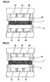
- a casting product reduction apparatus 30 includes, as illustrated in FIG. 2 and FIG 3 , casting product press rolls 31, 32 that come into contact with the long side surfaces of the casting product 1 and form a pair across the casting product 1, backup rolls 40 that support the casting product press rolls 31, 32, a first frame 51 that is arranged on one surface side of the casting product 1, and a second frame 52 that is arranged on the other surface side of the casting product 1.
- casting product press rolls 31, 32 are arranged in a casting product drawing direction Z respectively, and seven sets of casting product press rolls 31, 32 are arranged in this embodiment.
- the casting product press roll 31, 32 is configured such that its length in a roll axial direction is set to be larger than the long side width of the casting product 1. Further, the casting product press roll 31, 32 is pivotally supported by bearing parts 35 at both ends respectively, and is thereby rotatable around its center axis. Further, the roll gap between the casting product press roll 31 on the first frame 51 and the casting product press roll 32 on the second frame 52 is adjusted to get narrower as it goes to the downstream side in the casting product drawing direction Z.
- the roll diameter of the casting product press roll 31, 32 is set to 320 mm or less and the roll pitch in the casting product drawing direction Z is set to 340 mm or less.
- the backup rolls 40 that support the casting product press rolls 31, 32 respectively are arranged on the first frame 51 and the second frame 52. More specifically, three or more sets of the casting product press roll 31 and the backup roll 40 are arranged on the first frame 51 and three or more sets of the casting product press roll 32 and the backup roll 40 are arranged on the second frame 52 in the casting product drawing direction, and seven sets of the casting product press rolls 31, 32 are arranged in this embodiment.
- the backup roll 40 is divided into a plurality of parts in the axial direction of the casting product press roll 31, 32 (the width direction of the casting product 1) as illustrated in FIG. 2 , and is divided into three parts, that is, a first backup roll 41, a second backup roll 42, and a third backup roll 43.
- Each of the first backup roll 41, the second backup roll 42, and the third backup roll 43 is pivotally supported by bearing parts 45 at both ends respectively, and is thereby rotatable around the center axis thereof.
- the first frame 51 and the second frame 52 are coupled to each other by a plurality of reduction means 54.
- reduction means 54 provide a structure that the distance between the first frame 51 and the second frame 52 increases and decreases, and are thereby capable of adjusting the reduction force to the casting product 1.
- the reduction means 54 is composed of, for example, a hydraulic cylinder with a servo, and is configured such that one end of a cylinder rod 56 is fixed to the first frame 51 and the second frame 52 gets closer to and away from the first frame 51.
- molten steel is poured into the water-cooled mold 11 via an immersion nozzle 12 inserted into the water-cooled mold 11 and cooled by the primary cooling means of the water-cooled mold 11, whereby a solidified shell 2 grows and the casting product 1 is drawn out from below the water-cooled mold 11.
- an unsolidified portion 3 exists as illustrated in FIG 1 and FIG. 2 .
- This casting product 1 is drawn out downward by the pinch roll part 24 and bent by the bending roll part 25 as illustrated in FIG 1 . Then, the casting product 1 is bent back by the straightening roll part 26 and then conveyed in the horizontal direction by the horizontal roll part 27.
- the cooling water is sprayed toward the casting product 1 from the spray nozzles provided between the rolls of the pinch roll part 24, the bending roll part 25, the straightening roll part 26 and so on to cool the casting product 1, whereby the solidified shell 2 further grows. Then, at the side subsequent to the horizontal zone 17 where the casting product 1 is drawn out in the horizontal direction, the casting product 1 completely solidifies.
- the casting product 1 drawn from the water-cooled mold 11 is subjected to reduction by the casting product reduction apparatus 30 being this embodiment in the region where the center solid phase ratio becomes 0.2 or more.
- the upper limit of the center solid phase ratio of the casting product is 1.0 because it is the region where the problems such as center segregation and porosity occur.
- center solid phase ratio is defined as a solid phase ratio of a central portion in the casting product thickness direction and a molten portion in the casting product width direction.
- center solid phase ratio liquidus temperature - molten portion temperature / liquidus temperature - solidus temperature
- the molten portion temperature means the temperature of the central portion in the casting product thickness direction and the molten portion in the casting product width direction, and can be found by the heat transfer solidification calculation.
- the liquidus temperature can be calculated by referring to, for example, “ Tetsu to hagane, The journal of The Iron and Steel Institute of Japan, Vol. 55. No. 3 (19690227) S85 , The Iron and Steel Institute of Japan", and the solidus temperature can be calculated by referring to, for example, “ Hirai, Kanemaru, Mori: 19th Committee, Japan Society for the Promotion of Science, Fifth Solidification Phenomena Conference Material, Solidification 46 (December 1968 )"
- the casting product reduction apparatus 30 being this embodiment structured as described above includes the casting product press rolls 31, 32 and the backup rolls 40 that support the casting product press rolls 31, 32 respectively, so that the bearing parts 35 of the casting product press rolls 31, 32 and the bearing parts 45 of the backup rolls 40 can receive the load applied when applying reduction to the casting product 1. Consequently, it becomes possible to apply reduction to the casting product 1 with a relatively large reduction force and surely decrease the porosity.
- the casting product press roll 31, 32 is not divided in the roll axial direction and therefore can press the whole casting product 1 in the width direction and suppress occurrence of center segregation due to bulging deformation.
- the casting product reduction apparatus 30 in this embodiment it is unnecessary to increase the roll diameter for securing the stiffness of the casting product press rolls 31, 32, and therefore it is possible to densely arrange the casting product press rolls 31, 32 in the casting product drawing direction Z to thereby prevent the reduction force from locally acting and suppress internal cracks of the casting product. More specifically, since the casting product press rolls 31, 32 are set to 320 mm or less and the roll pitch in the casting product drawing direction Z is set to 340 mm or less, it becomes possible to apply reduction to the casting product 1 little by little at a small pitch to thereby sufficiently suppress internal cracks of the casting product 1.
- the size of the casting product press rolls 31, 32 and the lower limit of the roll pitch in the casting product drawing direction Z are not particularly limited but may be set in a range where actual operation is possible.
- the casting product press roll 31, 32 and the backup roll 40 are arranged in the casting product drawing direction Z on each of the first frame 51 and the second frame 52, and the reduction means 54 is provided at two or more places (at four places in this embodiment) on the first frame 51 and the second frame 52, the plurality of casting product press rolls 31, 32 can uniformly apply reduction to the casting product 1. Further, the bearing parts 35 arranged at the casting product press rolls 31, 32 can receive the reduction load.
- the reason why the number of sets of the casting product press roll 31, 32 and the backup roll 40 arranged on each frame is three or more in the casting product drawing direction Z is that if the size of the casting product press roll 31, 32 and the roll pitch in the casting product drawing direction Z are set in a range where actual operation is possible, two sets of them cannot uniformly apply reduction because of a large interval therebetween in the casting product drawing direction.
- the reduction means 54 on a pair of frames, at two places or more.
- the two places means both sides in the width direction of the casting product
- the reduction means 54 on the pair of frames provided on both sides in the width direction of the casting product enable uniform application of reduction to the casting product.
- the reduction means 54 is provided at two places also in the casting product drawing direction Z in addition to the two places on both sides in the width direction of the casting product, that is, at four places in total in this embodiment, so that a reduction gradient can also be given in the casting product drawing direction Z.
- the reduction force can be increased only by increasing the size of the device (for example, the cylinder diameter) constituting the reduction means provided on the frames, it becomes possible to give a larger reduction force without increasing the size of the reduction apparatus in a casting direction.
- the backup roll 40 is divided into a plurality of parts in the roll axial direction, not only the bearing parts 35 but also the plurality of bearing parts 45 arranged between the divided backup rolls 41, 42, 43 can also receive the reduction load, whereby it becomes possible to apply reduction to the casting product 1 with a larger reduction force to sufficiently decrease the porosity.
- the number of divisions in the roll axial direction of the backup roll 40 only needs to be plural (two or more), and a case of the number of divisions of three is exemplified in this embodiment.
- the upper limit of the number of divisions is not limited but may be set in a range where actual operation is possible.
- the high-quality casting product 1 can be manufactured in which occurrence of porosity, center segregation and internal cracks is suppressed.
- the casting product reduction apparatus including the backup roll divided into a plurality of parts
- the casting product reduction apparatus is not limited to this but may include one backup roll which is not divided.
- the backup roll by dividing the backup roll into a plurality of parts, it becomes possible to receive the reduction load in a distributed manner and apply reduction to the casting product with a larger reduction force, and therefore it is preferable to divide the backup roll into a plurality of parts.
- the reduction means has been described as the one using a hydraulic cylinder but is not limited to this.
- a mechanical reduction means 154 using a disc spring 155 and a screw jack 156 may be arranged on the first frame 151 and the second frame 152 as illustrated in FIG. 4 .
- the casting product reduction apparatus has been described as being arranged in the vertical bending continuous casting machine, but may be applied to a curved continuous casting machine, a vertical continuous casting machine, or a horizontal continuous casting machine.
- the casting product reduction apparatus of the present invention it is preferable to arrange the casting product reduction apparatus of the present invention at a position where bending strain or straightening strain does not occur in the casting product in the continuous casting machine.
- the position where the bending strain or the straightening strain does not occur in the casting product means a position except for a bending part and a straightening part among a vertical part, a bending part, a curved part, a straightening part, and a horizontal part constituting the continuous casting equipment.
- the casting product reduction apparatus may be arranged at any position of the vertical part, the curved part, and the horizontal part.
- the casting product reduction apparatus may be arranged at any position of the curved part and the horizontal part.
- the casting product reduction apparatus may be arranged at any position.
- the central solid phase ratio is 0 in a range of less than 2 m from the lower end of the mold, and it is preferable not to arrange the casting product reduction apparatus in this range. Accordingly, the improvement effects in the center segregation and so on can be achieved by arranging the casting product reduction apparatus at a position of 2 m or more from the lower end of the mold and cooling the casting product so that the central solid phase ratio is 0 or more.
- the range of the central solid phase ratio is not particularly limited, but may be a range of 0.2 to 1.0 as has been described, and may further be a range of 0.6 to 1.0 because the effects can be achieved even by applying reduction after solidification proceeds to a certain extent.
- any one or both of the casting product press rolls 31, 32 forming a pair across the casting product 1 may be configured to include a large-diameter portion 201 projecting outward in the diameter direction at its middle portion in the axial direction and small-diameter portions 202 respectively located on both ends of the large-diameter portion 201 as illustrated in FIG. 5 .
- the width W of the casting product 1 is 900 mm or more
- the one casting product press roll 31 is configured to press a middle region S1 in the width direction of the casting product 1 where the large-diameter portion 201 is located and not to press end regions S2 in the width direction of the casting product 1 where the small-diameter portions 202 are located.
- the end region S2 in the width direction of the casting product 1 is a region of 60 mm or more from the end in the width direction of the casting product 1 and 1.5 ⁇ t or less from the end in the width direction of the casting product 1 where the thickness of the casting product 1 is t.
- the end region S2 is a region of 60 mm or more from the end in the width direction of the casting product 1 and 360 mm or less from the end in the width direction of the casting product 1.
- the backup roll 40 that supports the one casting product press roll 32 is divided in the axial direction of the casting product press roll 32 (width direction of the casting product 1) and is divided into three parts, that is, a first backup roll 41, a second backup roll 42, and a third backup roll 43 as in the above-described embodiment.
- the backup roll 40 is arranged to support the large-diameter portion 201 of the casting product press roll 32.
- first backup roll 41, the second backup roll 42, and the third backup roll 43 have both ends pivotally supported by pivotal support parts 45 and thereby be rotatable about their respective center axes O b1 , O b2 , O b3 .
- the first backup roll 41 and the third backup roll 43 may be arranged on the downstream side in the drawing direction Z of the casting product 1 with respect to the casting product press roll 31, 32.
- the second backup roll 42 is arranged on the upstream side in the drawing direction Z of the casting product 1 with respect to the casting product press roll 31, 32.
- first backup roll 41 and the third backup roll 43, and the second backup roll 42 may hold the casting product press roll 31, 32 therebetween in the drawing direction Z.
- an angle ⁇ formed between a straight line linking the center axis O w of the casting product press roll 32 to the center axes O b1 , O b3 of the first backup roll 41 and the third backup roll 43 and the rolling reduction direction (vertical direction) as illustrated in FIG 7 is set to 5° or less.
- a difference amount X in the drawing direction Z between the center axis O w of the casting product press roll 32 and the center axes O b1 , O b3 of the first backup roll 41 and the third backup roll 43 is set to be within a range of sin 0.23° ⁇ (R w + R b ) ⁇ X ⁇ sin 5° ⁇ (R w + R b ).
- R w is the radius of the large-diameter portion 201 of the casting product press roll 32
- R b is the radius of the backup roll 40.
- a load of F/cos ⁇ that is the resultant force of the rolling reduction load F acting in the vertical direction and the load in the horizontal direction acts on the bearing parts of the backup roll arranged on the downstream side in the drawing direction of the casting product with respect to the casting product support roll.
- the angle ⁇ is set to ⁇ ⁇ 5°, thereby making it possible to prevent the load acting on the bearing parts of the backup roll from becoming excessive so as to increase the life of the bearing parts of the backup roll.
- the angle ⁇ is set to ⁇ ⁇ 0.23°, thereby allowing the backup roll to surely receive the drawing resistance so as to suppress deflection deformation in the drawing direction of the casting product support roll.
- an angle ⁇ ' formed between a straight line linking the center axis O w of the casting product press roll 32 to the center axis O b2 of the second backup roll 42 and the reduction direction (vertical direction) is set to 5° or less
- a difference amount X' in the drawing direction Z between the center axis O w of the casting product press roll 32 and the center axis O b2 of the second backup roll 42 is set to be within a range of sin 0.23° ⁇ (R w + R b ) ⁇ X' ⁇ sin 5° ⁇ (R w + R b ).
- the casting product 1 completely solidifies on the side subsequent to the horizontal zone 17 where the casting product 1 is drawn in the horizontal direction, and the horizontal roll part 27 at the horizontal zone 17 applies reduction to the casting product 1 as described in the above embodiment.
- a force in the reduction direction acts on the casting product press rolls 31, 32 due to the reduction reaction force.
- a force in the drawing direction Z acts on the casting product press rolls 31, 32 due to the drawing resistance when the casting product 1 moves in the drawing direction Z.
- the casting product press roll 32 has the large-diameter portion 201 projecting outward in the diameter direction at its middle portion in the axial direction and the small-diameter portions 202 located on both ends of the large-diameter portion 201, and the casting product press roll 32 is configured to press the middle region S1 in the width direction of the casting product 1 where the large-diameter portion 201 is located and not to press the end regions S2 in the width direction of the casting product 1 where the small-diameter portions 202 are located, thereby making it possible to apply reduction only to the middle region S1 in the width direction of the casting product 1 where the unsolidified portion 3 exists.
- reduction load can be greatly reduced.
- the casting product press roll 32 is supported by the backup roll 40, the deflection deformation of the casting product press roll 32 in the reduction direction can be suppressed.
- the drawing resistance acts only on the middle region S1 in the width direction where the unsolidified portion 3 exists, so that the deflection deformation in the drawing direction of the casting product press roll 32 can also be prevented.
- the end region S2 in the width direction of the casting product 1 where the small-diameter portion 202 is located is a region of 60 mm or more from the end in the width direction of the casting product 1 and 1.5 ⁇ t or less from the end in the width direction to the center side of the casting product 1, where the thickness of the casting product 1 is t.
- a region of 60 mm or more from the end in the width direction of the casting product 1 and 360 mm or less from the end in the width direction of the casting product 1 can be exemplified. This makes it possible to avoid application of reduction to the completely solidified region so as to surely reduce the reduction load. Further, the deflection deformation in the reduction direction and the deflection deformation in the drawing direction of the casting product press roll 31 can be suppressed.
- the backup roll 40 is divided into the first backup roll 41, the second backup roll 42, and the third backup roll 43 in the axial direction of the casting product press roll 32, the axial direction length of the backup roll 40 can be decreased and stiffness can be secured even with a small roll diameter.
- the first backup roll 41 and the third backup roll 43 are arranged on the downstream side in the drawing direction Z of the casting product 1 with respect to the casting product press roll 31, 32, so that the first backup roll 41 and the third backup roll 43 can receive the drawing resistance so as to suppress the deflection deformation in the drawing direction of the casting product press roll 31, 32.
- the second backup roll 42 is arranged on the upstream side in the drawing direction Z of the casting product 1 with respect to the casting product press roll 31, 32, and the first backup roll 41 and the third backup roll 43, and the second backup roll 42 hold the casting product press roll 31, 32 therebetween in the drawing direction Z, thereby suppressing occurrence of bending variation in the casting product press roll 31, 32 even if the casting speed (drawing speed of the casting product) is changed depending on the operation status.
- the difference amount X in the drawing direction Z between the center axis O w of the casting product press roll 32 and the center axes O b1 , O b3 of the first backup roll 41 and the third backup roll 43 is set to sin 0.23° ⁇ (R w + R b ) ⁇ X as described above. This makes it possible to surely transmit the drawing resistance applied on the casting product press roll 32 to the first backup roll 41 and the third backup roll 43 so as to prevent the deflection deformation in the drawing direction Z of the casting product press roll 32.
- the angle ⁇ formed between the straight line linking the center axis O w of the casting product press roll 32 to the center axes O b1 , O b3 of the first backup roll 41 and the third backup roll 43 and the reduction direction (vertical direction in this embodiment) is se to 45° or less, so that it is possible to transmit the load in the reduction direction to the first backup roll 41 and the third backup roll 43 so as to suppress the deflection deformation in the reduction direction of the casting product press roll 32.
- the difference amount X' in the drawing direction Z between the center axis O w of the casting product press roll 31 and the center axis O b2 of the second backup roll 42 is set to be within a range of sin 0.23°x (R w + R b ) ⁇ X' ⁇ sin 5°x (R w + R b ), and in the cross section perpendicular to the center axis O w of the casting product press roll 32, the angle ⁇ ' formed between the straight line linking the center axis O w of the casting product press roll 32 to the center axis O b2 of the second backup roll 42 and the reduction direction (vertical direction in this embodiment) is set to 5° or less, thereby making it possible to suppress the bending variation in the drawing direction Z of the casting product press roll 32 and receive the load in the reduction direction by the second backup roll 42.
- the backup rolls are described as being arranged on the downstream side and the upstream side with respect to the casting product press rolls in the above example, but the backup rolls are not limited to this and may be arranged only on the downstream side in the drawing direction with respect to the casting product press rolls or may be arranged such that the center axes of the casting product press rolls are located at the same position as those of the backup rolls in the drawing direction.
- the casting product press roll 32 that is one of the casting product press rolls 31, 32 forming a pair across the casting product is described as having the large-diameter portion 201 in the above example, but not limited to this, and both of the casting product press rolls 31, 32 forming a pair across the casting product may have respective large-diameter portions.
- the width of a target casting product is preferably 900 mm or more.
- the deflection deformation in the reduction direction of the casting product press rolls 31, 32 can be suppressed because the casting product press rolls 31, 32 are supported by the backup rolls. Further, the deflection deformation in the drawing direction of the casting product press rolls 31, 32 can also be suppressed. Accordingly, it becomes possible to surely apply reduction to the middle portion in the width direction of the casting product 1 to suppress occurrence of internal defects such as center segregation and porosity due to bulging deformation.
- the size of the casting product was 300 mm thick ⁇ 2200 mm wide, the casting speed was 0.9 m/min, and the two casting product reduction apparatuses were sequentially installed in the drawing direction of the casting product from a position of 22 m from the bottom of the mold so that the central solid phase ratio of the casting product where the casting product reduction apparatuses were installed was in a range of 0.2 to 1.0.
- the roll diameter of the casting product press roll and the backup roll was 270 mm and seven sets of casting product press rolls were arranged on the frames in the drawing direction of the casting product. Further, the first frame and the second frame were coupled to each other by four reduction means (hydraulic cylinders).
- a casting product reduction apparatus having a structure in which there was no backup roll and a casting product press roll 31, 32 was divided into three parts in the roll axial direction as illustrated in FIG 8 was used.
- a casting product reduction apparatus having a structure in which casting product press rolls 31, 32 having roll axial direction lengths larger than the width of the casting product were provided and a backup roll 40 divided into two parts in the roll axial direction was arranged for each one of the casting product press rolls as illustrated in FIG 10 was used.
- a casting product reduction apparatus having a structure in which casting product press rolls 31, 32 having roll axial direction lengths larger than the width of the casting product were provided, the casting product press roll 32 on the upper side had a large-diameter portion projecting outward in the diameter direction at the middle portion in the axial direction, and a backup roll 40 divided into three parts in the roll axial direction was arranged for each one of the casting product press rolls as illustrated in FIG 12 was used.
- the roll diameter of the large-diameter portion pressing the casting product was 270 mm and the roll diameter of the other portion was 255 mm.
- the length of the large-diameter portion was 1900 mm.
- the range of the large-diameter portion supported by a plurality of backup rolls was 1890 mm.
- the reduction force index when evaluating the experimental result was obtained by adjusting the reduction force so that the largest value of the distributed load on each bearing (each bearing of the casting product press rolls and each bearing of the backup rolls) measured by a load cell arranged under the bearing during casting satisfies the following Expression (1) and using the value in the conventional example as a standard.
- basic static load rating of the bearing / distributed load on the bearing 5.0
- the reduction amount index was obtained by measuring the thickness of the casting product after casting, finding the difference in thickness between the case of applying the reduction and the case of not applying the reduction as a reduction amount applied to the casting product, and indicating the reduction amount in a relative value using the reduction amount in the conventional example as a standard.
- the bulging index was obtained by evaluating the maximum value of the deformation amount in the thickness direction of the casting product using finite element method analysis and indicating the maximum value in a relative value using the value in the conventional example as a standard.
- the center segregation index was obtained from the following Expression (2). casting product Mn segregation degree / casting product Mn segregation degree in conventional example - 1
- the casting product Mn segregation degree is (maximum value of Mn concentration of Mn segregation part)/(Mn concentration of the whole casting product) and was measured in the following procedure.
- Samples of 50 mm ⁇ 50 mm were obtained mainly from middle portions in the thickness direction of the casting product at 10 places, which are positions uniformly divided along the width direction of the casting product, and the surfaces of the samples were polished and then subjected to line analysis with X ray in the thickness direction of the casting product for measurement of the peak values of the Mn concentrations, which were regarded as the Mn concentrations of the Mn segregation parts.
- Mn concentration of the whole casting product the value obtained by analysis and measurement at the stage of molten steel was used.
- the porosity index was obtained by cutting a sample with a thickness of 20 mm including the middle portion in the thickness direction from the casting product, finding a total cross section area of the porosity with respect to the cross section area in the thickness direction of the casting product by X-ray transmission photography, and indicating the total cross section area in a relative value using the area ratio in the conventional example as a standard.
- Example 1 Casting results reduction force index reduction amount index bulging index porosity index center segregation index Comparative Example 1 1.0 1 1 1 Invention Example 1 0.85 0.9 0.60 0.85 0.60 Invention Example 2 1.20 1.3 0.60 0.60 0.30 Invention Example 3 1.50 1.8 0.60 0.45 0.25 Invention Example 4 1.40 2.4 0.60 0.30 0.24
- the deflection amount of the casting product press roll in the reduction direction was evaluated in the following cases:
- each bearing of the roll was fixed by a plate being an elastic body.
- the thickness of the plate was 40 mm, and the height of the plate was 500 mm.
- the roll diameter was ⁇ 300 mm, and a cooling water hole of 50 mm was bored.
- the size of the casting product was 300 mm thick ⁇ 2200 mm wide. It was obtained by calculation that when the reduction was applied to the casting product having the cross section by 0.6 mm per casting product press roll, the average drawing resistance in the range of 200 mm from the end in the width direction of the casting product was about 2.3 times the drawing resistance by a molten steel static pressure of the unsolidified portion.
- the end region in the width direction of the casting product which was not subjected to the reduction by the large-diameter portion of the casting product press roll in (1), (3) was 200 mm on either side. Note that in each case (1), (2), (3), the center axis of the casting product press roll and the center axis of the backup roll coincide each other in the drawing direction.
- the calculation results are illustrated in FIG. 17 . From the comparison between (1) and (2), it was confirmed that only one (upper side) of the casting product press rolls forming a pair across the casting product having a large-diameter portion at the middle portion in the axial direction could decrease the reduction load acting on both of the casting product press rolls forming a pair to suppress the deflection deformation of both of the casting product press rolls forming a pair down to about two thirds. Thus, the life until permanent deformation occurs in the casting product press rolls can be greatly increased. Further, a high-quality casting product can be manufactured which has less internal defects such as center segregation and porosity due to bulging deformation caused by the deformation of the casting product press rolls.
- the calculation results are illustrated in FIG 21 . From the comparison between (4) and (5), it was confirmed that only one (upper side) of the casting product press rolls forming a pair across the casting product having a large-diameter portion at the middle portion in the axial direction could decrease the reduction load acting on both of the casting product press rolls forming a pair and, as a result, decrease the drawing resistance because the drawing resistance was proportional to the reduction load, and suppress the deflection deformation in the drawing direction of the casting product press rolls by about three out of ten. Thus, the life until permanent deformation occurs in the casting product press rolls can be greatly increased. Further, a high-quality casting product can be manufactured which has less internal defects such as center segregation and porosity due to bulging deformation caused by the deformation of the casting product press rolls.
- the internal crack occurrence rate indicates the probability that the internal crack was visually confirmed at one or more places on an etch print in a cross section in the casting direction of a randomly selected casting product.
- the experiment conditions and the results of the internal crack occurrence rate are illustrated in Table 2.
Applications Claiming Priority (3)
| Application Number | Priority Date | Filing Date | Title |
|---|---|---|---|
| JP2012004101 | 2012-01-12 | ||
| JP2012137020 | 2012-06-18 | ||
| PCT/JP2013/050592 WO2013105670A1 (fr) | 2012-01-12 | 2013-01-15 | Dispositif de réduction de pièce coulée |
Publications (2)
| Publication Number | Publication Date |
|---|---|
| EP2803427A1 true EP2803427A1 (fr) | 2014-11-19 |
| EP2803427A4 EP2803427A4 (fr) | 2016-01-06 |
Family
ID=48781610
Family Applications (1)
| Application Number | Title | Priority Date | Filing Date |
|---|---|---|---|
| EP13736021.0A Withdrawn EP2803427A4 (fr) | 2012-01-12 | 2013-01-15 | Dispositif de réduction de pièce coulée |
Country Status (7)
| Country | Link |
|---|---|
| US (1) | US10226801B2 (fr) |
| EP (1) | EP2803427A4 (fr) |
| KR (1) | KR101623671B1 (fr) |
| CN (1) | CN104169025B (fr) |
| BR (1) | BR112014016984B1 (fr) |
| CA (1) | CA2860497C (fr) |
| WO (1) | WO2013105670A1 (fr) |
Families Citing this family (9)
| Publication number | Priority date | Publication date | Assignee | Title |
|---|---|---|---|---|
| US9782824B2 (en) * | 2013-05-02 | 2017-10-10 | Nippon Steel and Sumitomo Metal Corporation | Continuous casting equipment |
| JP5870966B2 (ja) * | 2013-05-31 | 2016-03-01 | Jfeスチール株式会社 | 連続鋳造鋳片の製造方法 |
| JP6350199B2 (ja) * | 2014-10-17 | 2018-07-04 | 新日鐵住金株式会社 | 連続鋳造用鋳片支持装置及び鋳片支持方法 |
| US10532386B2 (en) * | 2015-01-15 | 2020-01-14 | Nippon Steel Corporation | Continuous-cast slab, method and apparatus of manufacturing the same, and method and apparatus of manufacturing thick steel plate |
| CN105983668A (zh) * | 2015-02-27 | 2016-10-05 | 新日铁住金工程技术株式会社 | 轻压下辊、具有其的轻压下装置及铸坯的制造方法 |
| US9334394B1 (en) | 2015-06-03 | 2016-05-10 | Fina Technology, Inc. | Farnesene resins, rubber compositions, and tire compositions |
| CN106392031B (zh) * | 2015-07-31 | 2018-04-06 | 新日铁住金工程技术株式会社 | 铸坯压下装置 |
| JP6961295B2 (ja) * | 2017-05-25 | 2021-11-05 | 日本製鉄株式会社 | 連続鋳造鋳片のクレータエンド位置検出装置、それが組み込まれたロールセグメント、及びそれらを用いた連続鋳造鋳片のクレータエンド位置検出方法 |
| TWI622434B (zh) * | 2017-06-28 | 2018-05-01 | 中國鋼鐵股份有限公司 | 鑄胚及其製造方法 |
Family Cites Families (30)
| Publication number | Priority date | Publication date | Assignee | Title |
|---|---|---|---|---|
| JPS5178738A (en) * | 1974-12-30 | 1976-07-08 | Nippon Steel Corp | Renzokuchuzoyo chuhentosetsurooruno batsukuatsupuroorusochi |
| JPS5445217U (fr) * | 1977-09-02 | 1979-03-28 | ||
| JPS5445217A (en) | 1978-08-21 | 1979-04-10 | Minoru Sangyo | Riceetransplanting method utilizing potted nursery rice plant |
| JPS5510400A (en) * | 1979-07-09 | 1980-01-24 | Kobe Steel Ltd | Roll stand for guiding cast billet |
| JPS56128651A (en) * | 1980-03-12 | 1981-10-08 | Nisshin Steel Co Ltd | Support roll device for continuous casting equipment |
| JPS58185356U (ja) * | 1982-06-02 | 1983-12-09 | 川崎製鉄株式会社 | 連続鋳造設備の鋳片支持装置 |
| JPS61132249A (ja) * | 1984-12-03 | 1986-06-19 | Sumitomo Heavy Ind Ltd | 連続鋳造機用ロ−ルスタンド |
| US5115857A (en) * | 1990-07-18 | 1992-05-26 | Voest-Alpine Industrieanlagenbau G.M.B.H. | Strand guide arrangement provided at a continuous casting plant |
| DE4138740A1 (de) | 1991-11-26 | 1993-05-27 | Schloemann Siemag Ag | Verfahren und vorrichtung zum stranggiessen von brammen oder bloecken |
| JP2732996B2 (ja) | 1993-01-18 | 1998-03-30 | 株式会社神戸製鋼所 | 連続鋳造用のロール装置 |
| JPH08132205A (ja) | 1994-11-10 | 1996-05-28 | Sanyo Special Steel Co Ltd | 連続鋳造における鋳片の中心偏析改善方法及び装置 |
| JPH08238550A (ja) * | 1995-02-28 | 1996-09-17 | Nkk Corp | 鋼の連続鋳造方法 |
| JPH08257715A (ja) | 1995-03-22 | 1996-10-08 | Nippon Steel Corp | 連続鋳造方法 |
| JP2809186B2 (ja) * | 1996-02-19 | 1998-10-08 | 株式会社神戸製鋼所 | 連続鋳造方法 |
| JPH10328799A (ja) | 1997-05-30 | 1998-12-15 | Kawasaki Steel Corp | 連続鋳造機の鋳片支持装置 |
| DE19745056A1 (de) * | 1997-10-11 | 1999-04-15 | Schloemann Siemag Ag | Verfahren und Anlage zur Erzeugung von Brammen in einer Stranggießanlage |
| US6520245B2 (en) * | 1998-03-09 | 2003-02-18 | Sms Schloemann-Siemag Aktiengesellschaft | Guide element of a continuous casting plant |
| JPH11291007A (ja) | 1998-04-08 | 1999-10-26 | Kawasaki Steel Corp | 連続鋳造鋳片支持装置 |
| JP2000312956A (ja) | 1999-04-27 | 2000-11-14 | Hitachi Zosen Corp | 連続鋳造設備におけるロールセグメント装置および連続鋳造設備用のロールセグメント装置の分割用治具 |
| CN1140364C (zh) | 1999-11-25 | 2004-03-03 | 宝山钢铁股份有限公司 | 连铸机可分式扇形段 |
| JP3603033B2 (ja) * | 2001-02-20 | 2004-12-15 | 株式会社日立製作所 | クラスター式多段圧延機 |
| JP2003094154A (ja) | 2001-09-21 | 2003-04-02 | Sanyo Special Steel Co Ltd | 鋼の連続鋳造方法 |
| JP4110209B2 (ja) * | 2002-07-03 | 2008-07-02 | 株式会社ジェイテクト | 連続鋳造機のロール装置および連続鋳造機のロール支持用円筒ころ軸受 |
| JP4722644B2 (ja) | 2005-09-22 | 2011-07-13 | 株式会社ジェイテクト | 連続鋳造機用多分割ロール装置 |
| DE102006040012A1 (de) | 2006-08-25 | 2008-02-28 | Sms Demag Ag | Strangführungseinrichtung und Verfahren zum Führen eines noch nicht durcherstarrten Metallbandes |
| CN100574936C (zh) | 2007-11-01 | 2009-12-30 | 中冶连铸技术工程股份有限公司 | 连铸机辊件的托辊支撑装置 |
| JP5377056B2 (ja) | 2008-04-21 | 2013-12-25 | 新日鉄住金エンジニアリング株式会社 | 凝固後鋳片のロール圧下方法 |
| JP5330170B2 (ja) * | 2009-09-10 | 2013-10-30 | 株式会社神戸製鋼所 | 連続鋳造設備の鋳片圧下ロールスタンド |
| JP5723214B2 (ja) * | 2011-05-16 | 2015-05-27 | 新日鉄住金エンジニアリング株式会社 | 連続鋳造設備のガイドロールセグメント |
| CN102389957A (zh) | 2011-11-21 | 2012-03-28 | 中冶连铸技术工程股份有限公司 | 整体式辊子的偏心支撑装置 |
-
2013
- 2013-01-15 BR BR112014016984-5A patent/BR112014016984B1/pt active IP Right Grant
- 2013-01-15 EP EP13736021.0A patent/EP2803427A4/fr not_active Withdrawn
- 2013-01-15 CA CA2860497A patent/CA2860497C/fr not_active Expired - Fee Related
- 2013-01-15 US US14/371,961 patent/US10226801B2/en active Active
- 2013-01-15 KR KR1020147019938A patent/KR101623671B1/ko active IP Right Grant
- 2013-01-15 CN CN201380005164.7A patent/CN104169025B/zh active Active
- 2013-01-15 WO PCT/JP2013/050592 patent/WO2013105670A1/fr active Application Filing
Also Published As
| Publication number | Publication date |
|---|---|
| CN104169025B (zh) | 2016-08-31 |
| EP2803427A4 (fr) | 2016-01-06 |
| KR101623671B1 (ko) | 2016-05-23 |
| KR20140114379A (ko) | 2014-09-26 |
| CN104169025A (zh) | 2014-11-26 |
| CA2860497C (fr) | 2017-06-13 |
| WO2013105670A1 (fr) | 2013-07-18 |
| US10226801B2 (en) | 2019-03-12 |
| BR112014016984A2 (pt) | 2017-06-13 |
| BR112014016984B1 (pt) | 2020-05-12 |
| US20150047403A1 (en) | 2015-02-19 |
| BR112014016984A8 (pt) | 2017-07-04 |
| CA2860497A1 (fr) | 2013-07-18 |
Similar Documents
| Publication | Publication Date | Title |
|---|---|---|
| EP2803427A1 (fr) | Dispositif de réduction de pièce coulée | |
| EP3144080B1 (fr) | Procédé de coulée continue de brame | |
| US8256494B2 (en) | Metal-strip guiding apparatus | |
| EP3219408B1 (fr) | Procédé de coulée continue pour de l'acier | |
| EP2929956B1 (fr) | Installation de coulée continue | |
| EP3246113B1 (fr) | Brame coulée en continu, son procédé et dispositif de fabrication | |
| EP3012044A1 (fr) | Procédé de coulée continue pour pièce coulée pour tôle d'acier extra-épaisse | |
| EP3473346B1 (fr) | Procédé de laminage à froid d'une tôle d'acier, et procédé de fabrication de tôle d'acier | |
| EP3782747B1 (fr) | Méthode de mise en forme et de réduction douce pour la coulée continue de l'acier | |
| EP3760339B1 (fr) | Méthode de coulée continue de l'acier utilisant la réduction douce avec une légère charge de laminage | |
| JP5810651B2 (ja) | 鋼片の連続鋳造方法 | |
| EP3845329B1 (fr) | Rouleau convexe à courbure continue pour la coulée continue de blooms, et procédé pour le fabriquer | |
| JP6045509B2 (ja) | 鋳片圧下装置 | |
| JP2017100140A (ja) | 鋼の連続鋳造方法 | |
| JP4364852B2 (ja) | スラブ鋳片の連続鋳造設備と連続鋳造方法 | |
| JP3104627B2 (ja) | 丸ビレットの未凝固圧下製造方法 | |
| JP6299413B2 (ja) | スラブの連続鋳造方法 | |
| JPH03110049A (ja) | 連続鋳造用分割ロールの軸受装置 | |
| JP5919141B2 (ja) | 鋳片支持ロールユニット、連続鋳造装置及び連続鋳造方法 | |
| JP3498586B2 (ja) | 連続鋳造方法 | |
| JPH06134558A (ja) | 鋼の連続鋳造機 |
Legal Events
| Date | Code | Title | Description |
|---|---|---|---|
| PUAI | Public reference made under article 153(3) epc to a published international application that has entered the european phase |
Free format text: ORIGINAL CODE: 0009012 |
|
| 17P | Request for examination filed |
Effective date: 20140807 |
|
| AK | Designated contracting states |
Kind code of ref document: A1 Designated state(s): AL AT BE BG CH CY CZ DE DK EE ES FI FR GB GR HR HU IE IS IT LI LT LU LV MC MK MT NL NO PL PT RO RS SE SI SK SM TR |
|
| DAX | Request for extension of the european patent (deleted) | ||
| RA4 | Supplementary search report drawn up and despatched (corrected) |
Effective date: 20151203 |
|
| RIC1 | Information provided on ipc code assigned before grant |
Ipc: B22D 11/128 20060101AFI20151127BHEP |
|
| STAA | Information on the status of an ep patent application or granted ep patent |
Free format text: STATUS: EXAMINATION IS IN PROGRESS |
|
| 17Q | First examination report despatched |
Effective date: 20180328 |
|
| RAP1 | Party data changed (applicant data changed or rights of an application transferred) |
Owner name: NIPPON STEEL & SUMITOMO METAL CORPORATION |
|
| RAP1 | Party data changed (applicant data changed or rights of an application transferred) |
Owner name: NIPPON STEEL CORPORATION |
|
| GRAP | Despatch of communication of intention to grant a patent |
Free format text: ORIGINAL CODE: EPIDOSNIGR1 |
|
| STAA | Information on the status of an ep patent application or granted ep patent |
Free format text: STATUS: GRANT OF PATENT IS INTENDED |
|
| INTG | Intention to grant announced |
Effective date: 20201117 |
|
| RAP1 | Party data changed (applicant data changed or rights of an application transferred) |
Owner name: NIPPON STEEL CORPORATION |
|
| RIN1 | Information on inventor provided before grant (corrected) |
Inventor name: YAMASAKI, NORIMASA Inventor name: MARUKI, YASUO Inventor name: MATSUOKA, YUKIHIRO Inventor name: HAYAMA, MASANOBU Inventor name: IMAI, SHUNTARO Inventor name: SENOO, SATOSHI |
|
| STAA | Information on the status of an ep patent application or granted ep patent |
Free format text: STATUS: THE APPLICATION IS DEEMED TO BE WITHDRAWN |
|
| 18D | Application deemed to be withdrawn |
Effective date: 20210330 |