EP2802781B2 - Gasregeleinheit in modularer bauweise und gasregelventil - Google Patents
Gasregeleinheit in modularer bauweise und gasregelventil Download PDFInfo
- Publication number
- EP2802781B2 EP2802781B2 EP13708725.0A EP13708725A EP2802781B2 EP 2802781 B2 EP2802781 B2 EP 2802781B2 EP 13708725 A EP13708725 A EP 13708725A EP 2802781 B2 EP2802781 B2 EP 2802781B2
- Authority
- EP
- European Patent Office
- Prior art keywords
- gas
- valve
- housing
- valve body
- axial direction
- Prior art date
- Legal status (The legal status is an assumption and is not a legal conclusion. Google has not performed a legal analysis and makes no representation as to the accuracy of the status listed.)
- Active
Links
Images

Classifications
-
- F—MECHANICAL ENGINEERING; LIGHTING; HEATING; WEAPONS; BLASTING
- F16—ENGINEERING ELEMENTS AND UNITS; GENERAL MEASURES FOR PRODUCING AND MAINTAINING EFFECTIVE FUNCTIONING OF MACHINES OR INSTALLATIONS; THERMAL INSULATION IN GENERAL
- F16K—VALVES; TAPS; COCKS; ACTUATING-FLOATS; DEVICES FOR VENTING OR AERATING
- F16K27/00—Construction of housing; Use of materials therefor
-
- F—MECHANICAL ENGINEERING; LIGHTING; HEATING; WEAPONS; BLASTING
- F16—ENGINEERING ELEMENTS AND UNITS; GENERAL MEASURES FOR PRODUCING AND MAINTAINING EFFECTIVE FUNCTIONING OF MACHINES OR INSTALLATIONS; THERMAL INSULATION IN GENERAL
- F16K—VALVES; TAPS; COCKS; ACTUATING-FLOATS; DEVICES FOR VENTING OR AERATING
- F16K31/00—Actuating devices; Operating means; Releasing devices
- F16K31/02—Actuating devices; Operating means; Releasing devices electric; magnetic
- F16K31/04—Actuating devices; Operating means; Releasing devices electric; magnetic using a motor
-
- F—MECHANICAL ENGINEERING; LIGHTING; HEATING; WEAPONS; BLASTING
- F16—ENGINEERING ELEMENTS AND UNITS; GENERAL MEASURES FOR PRODUCING AND MAINTAINING EFFECTIVE FUNCTIONING OF MACHINES OR INSTALLATIONS; THERMAL INSULATION IN GENERAL
- F16K—VALVES; TAPS; COCKS; ACTUATING-FLOATS; DEVICES FOR VENTING OR AERATING
- F16K27/00—Construction of housing; Use of materials therefor
- F16K27/02—Construction of housing; Use of materials therefor of lift valves
- F16K27/029—Electromagnetically actuated valves
-
- F—MECHANICAL ENGINEERING; LIGHTING; HEATING; WEAPONS; BLASTING
- F16—ENGINEERING ELEMENTS AND UNITS; GENERAL MEASURES FOR PRODUCING AND MAINTAINING EFFECTIVE FUNCTIONING OF MACHINES OR INSTALLATIONS; THERMAL INSULATION IN GENERAL
- F16K—VALVES; TAPS; COCKS; ACTUATING-FLOATS; DEVICES FOR VENTING OR AERATING
- F16K39/00—Devices for relieving the pressure on the sealing faces
-
- F—MECHANICAL ENGINEERING; LIGHTING; HEATING; WEAPONS; BLASTING
- F23—COMBUSTION APPARATUS; COMBUSTION PROCESSES
- F23N—REGULATING OR CONTROLLING COMBUSTION
- F23N1/00—Regulating fuel supply
- F23N1/005—Regulating fuel supply using electrical or electromechanical means
-
- F—MECHANICAL ENGINEERING; LIGHTING; HEATING; WEAPONS; BLASTING
- F23—COMBUSTION APPARATUS; COMBUSTION PROCESSES
- F23N—REGULATING OR CONTROLLING COMBUSTION
- F23N2235/00—Valves, nozzles or pumps
- F23N2235/02—Air or combustion gas valves or dampers
-
- F—MECHANICAL ENGINEERING; LIGHTING; HEATING; WEAPONS; BLASTING
- F23—COMBUSTION APPARATUS; COMBUSTION PROCESSES
- F23N—REGULATING OR CONTROLLING COMBUSTION
- F23N2235/00—Valves, nozzles or pumps
- F23N2235/12—Fuel valves
- F23N2235/14—Fuel valves electromagnetically operated
-
- F—MECHANICAL ENGINEERING; LIGHTING; HEATING; WEAPONS; BLASTING
- F23—COMBUSTION APPARATUS; COMBUSTION PROCESSES
- F23N—REGULATING OR CONTROLLING COMBUSTION
- F23N2235/00—Valves, nozzles or pumps
- F23N2235/12—Fuel valves
- F23N2235/18—Groups of two or more valves
-
- F—MECHANICAL ENGINEERING; LIGHTING; HEATING; WEAPONS; BLASTING
- F23—COMBUSTION APPARATUS; COMBUSTION PROCESSES
- F23N—REGULATING OR CONTROLLING COMBUSTION
- F23N2235/00—Valves, nozzles or pumps
- F23N2235/12—Fuel valves
- F23N2235/24—Valve details
-
- Y—GENERAL TAGGING OF NEW TECHNOLOGICAL DEVELOPMENTS; GENERAL TAGGING OF CROSS-SECTIONAL TECHNOLOGIES SPANNING OVER SEVERAL SECTIONS OF THE IPC; TECHNICAL SUBJECTS COVERED BY FORMER USPC CROSS-REFERENCE ART COLLECTIONS [XRACs] AND DIGESTS
- Y10—TECHNICAL SUBJECTS COVERED BY FORMER USPC
- Y10T—TECHNICAL SUBJECTS COVERED BY FORMER US CLASSIFICATION
- Y10T137/00—Fluid handling
- Y10T137/8593—Systems
- Y10T137/87917—Flow path with serial valves and/or closures
Definitions
- the invention relates to a gas control unit of modular design, in particular for controlling the amount of gas to be supplied to a gas burner, and to a gas control valve designed in its entirety as a module, which can be used in such a modular gas control unit.
- gas control valves or gas safety valves have to be specially matched to a specific housing shape of the mixing device or the blower and can only be used for this one product.
- the object of the invention to provide a gas control unit and a gas control valve that can be used in it, which can be used in different housing types, in particular of mixing devices or blowers. Furthermore, the object of the invention is to reduce the assembly time of the units responsible for the gas regulation and to shorten the tests to be carried out for the function and tightness.
- a gas control valve comprises a housing with a gas inlet, a valve body held in the housing and arranged to be movable in a first and second axial direction, a valve seat, at least one first spring which acts on the valve body in the first axial direction, a spring which is movable in the axial direction , with the valve body indirectly engaged axle, a drive acting on the axle, which moves this and thus the valve body in predefined length sections in the axial direction to open and close the gas control valve, the drive being an electronically controlled stepping motor and the gas control valve in its entirety is designed as a replaceable module.
- the gas control valve does not have to fulfill any safety functions.
- Replaceable module means that the gas control valve is designed as an independent component and can be combined with other components. Due to the design as a module, the gas control valve can be attached to any components provided for this purpose and removed again via a suitable interface.
- the axis is preferably metallic.
- At least part of the housing is designed as an insert cartridge, whereby the gas control valve designed as a module can be compactly constructed and inserted or screwed into housings of blower devices or gas-air mixing devices. It is favorable here if a thread, a flange or a comparable detachable fastening means is provided on the outside of the housing designed as an insertable cartridge. It is also advantageous that the components determining the gas flow or the gas quantity are accommodated in such an insert cartridge and are therefore located in the gas flow path when the cartridge is screwed into the corresponding housing.
- the “insert cartridge” is defined here as a housing part that is suitable for being inserted into another component without further construction-related measures having to be provided on the other component in addition to a corresponding shape adjustment.
- the gas control valve is designed with a direct pressure regulator, with the valve body being held in the center by a membrane and the gas inlet taking place in the axial direction between the membrane and the valve seat, so that a gas pressure in the first axial direction is against the membrane and in the second, opposite direction axial direction against the valve body or against acts in radially outwardly extending sections of the valve body.
- the valve body is thus in a force equilibrium, influenced by the spring force of the first spring, the external pressure and the gas pressure against the membrane holding the valve body in a first axial direction and the gas pressure and the force of the drive on the valve body in a second axial direction.
- the stepping motor that generates this axial movement can be designed in a very simple and comparatively inexpensive manner, which leads to a considerable reduction in the overall costs of the gas control valve in a modular design.
- the diameter of the housing and the size of the released gas path of the gas control valve can also be dimensioned much larger than controllers known from the prior art due to the provision of the force balance, without adversely affecting the control accuracy.
- a size "c" of 30-50 mm, preferably 30-40 mm is preferred as the outside diameter of the housing, and the size of the released gas path with a gap width "b" of 2-5 mm is preferred.
- the movement of the valve body in the second axial direction is more precisely regulated in that a second spring is arranged between the axle and the valve body, which spring acts on the valve body in the second axial direction.
- a second spring is arranged between the axle and the valve body, which spring acts on the valve body in the second axial direction.
- the predetermined opening positions of the valve body can then be controlled electronically via individual steps and half steps.
- the second spring is arranged inside the hollow valve body and extends in the axial direction along the axis of the drive or stepper motor.
- the valve seat is formed by parts of the housing of the gas control valve, in particular by parts of the insert cartridge, so that additional components within the modular gas control valve can be dispensed with as far as possible and the design can therefore be made as small as possible, especially in the axial direction.
- sections of the housing of the gas control valve, designed as an insert cartridge extend in the radial direction towards the center and form the valve seat with their edge region pointing radially inwards.
- the direct pressure regulator can be separated from the drive, in particular the stepping motor, by a preferably metal sealing plate, with the sealing plate being arranged between the stepping motor and the membrane.
- a recess is provided in the central area of the sealing plate, through which the axis extends and creates an indirect connection between the drive, in particular the stepper motor, and the valve body.
- the sealing plate does not seal the direct pressure regulator absolutely, but only to the extent required by the standards (e.g. DIN-EN 13611), whereby in the event of a fault a certain amount of gas (less than 70 liters/hour) may escape through the recess in the sealing plate.
- An embodiment of the gas control valve with a sealing plate is favorable in that the drive used, in particular a stepper motor, does not itself have to be designed to be gas-tight and is therefore significantly more cost-effective.
- the gas control valve shown above is combined with a gas safety valve, also designed as a module, to form a gas control unit of modular design, in particular for controlling the amount of gas to be supplied to a gas burner.
- the gas control valve designed as a module is arranged in series with the gas safety valve designed as a module in such a way that the gas safety valve is located in front of the gas control valve, viewed in the direction of flow.
- each module only has to be developed once, but can later be used in various end products, for example in fan housings, gas valve housings or gas-air manifolds.
- each of the modules can be manufactured separately and its function tested, whereby the test devices for the modular valves can be significantly smaller than those used in the prior art for the overall components, e.g. fan housing with safety valves and a gas control valve arranged thereon had to.
- Another advantage of the modular design is that several of the respective gas control valves and gas safety valves, which are formed as modules, can be attached in parallel to the respective end products and thus achieve greater performance in a simple and cost-effective manner and modulation widths can be achieved.
- only a single gas safety valve is provided for the gas control unit and this is designed as a double safety valve.
- the need for a double seal of components arranged in the gas path can be taken into account without the installation space required for this being large, as would be the case if two separately arranged safety valves were used.
- the gas safety valve also has a cartridge-like housing with means for detachable attachment to a gas valve housing, fan housing or elbow. Furthermore, in an advantageous embodiment it is provided that on the cartridge-like housing parts of the two modular valves there are sealing means arranged on the outside for sealing the modules on the gas valve housing, fan housing or elbow. Due to the cartridge-like design of the respective housing, this can be done in the form of cost-effective sealing rings, which are introduced in a sealing manner between the gas valve housing, fan housing or manifold and the respective module.
- the gas valve housing, fan housing or manifold in terms of material properties or surface, since both the leakage protection and the gas control are carried out exclusively via the modular gas safety valves and the gas control valve. All that has to be provided is a receiving area that matches the modules or cartridge-like housings and into which the respective module is inserted and detachably fastened therein.
- the modularly formed valves and the gas valve housing, fan housing or manifold each have threads that match one another.
- other types of fastening such as flange screw connections, clip connections or other solutions known from the prior art are also possible.
- a combined unit of gas valve housing, fan housing or manifold with the gas control valve designed as a module and the gas safety valve designed as a module is at least 20% smaller in size than previously used corresponding units in which gas control valves and gas safety valves were used in a non-modular design.
- the overall size reduction is at least 40% compared to solutions known from the prior art.
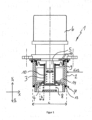
- FIG 1 a gas control valve 1 with a drive designed as a stepper motor 6, which is arranged on a direct pressure regulator, is shown.
- the gas control valve 1 is designed in its entirety as an exchangeable module, with the housing 2 being the part of the module that is inserted into the respective end product (e.g. gas valve housing, fan housing, manifold and fixed therein.
- the housing 2 is designed as a cartridge 7 for this purpose, which is arranged in the area of the gas flow during operation and accommodates the components that regulate the amount of gas per time to the stepping motor 6.
- a compensation opening 17 enables the pressure to be equalized in the region above the diaphragm 9.
- the housing 2 has a section 14 which extends in the radial direction towards the center and forms the valve seat 4 for the valve body 3.
- a first spring 8 is arranged on the valve body 3 and acts on the valve body 3 in the first axial direction Y1 and presses it against the valve seat 4 .
- the gas inlet into the gas control valve 1 takes place in the axial direction between the membrane 9 and the valve seat 4, so that the gas pressure in the first axial direction Y1 against the membrane 9 and in the second, opposite axial direction Y2 against the valve body 3 or against the valve body 3 acts in the radially outwardly extending sections.
- the force exerted by the gas pressure on the valve body 3 thus takes place in both axial directions Y1, Y2 and the sum is essentially equal to zero.
- the stepping motor 6 has an axis 5 via which a force can be applied indirectly to the valve body 3 in the second axial direction Y2 in order to move the latter.
- a second axially extending spring 10 is arranged inside the valve body 3, on which the axis 5 of the stepping motor 6 acts in the second axial direction Y2 in order to release the valve body 3 from the valve seat 4.
- the force applied by the stepping motor 6 via the second spring 10 takes place against the force of the first spring 8 and the external pressure prevailing outside of the gas control valve 1 .
- the valve body 3 is in a force equilibrium via the forces of the gas pressure and the spring forces, so that each axial offset of the axis 5 in the second axial direction Y2 directly means a corresponding lift of the valve body 3 from the valve seat 4 .
- This balance of forces makes it possible to increase the diameter of the housing 2, the valve body 3 and the gas path (valve gap with opening width b) released by the valve body 3, so that the absolutely necessary stroke in the axial direction of the valve body 3 from the valve seat is limited to 3mm can.
- the housing 2 has an outside diameter of 30-50mm
- the valve body has an outside diameter of 15-25mm
- the circumferential valve gap released for the gas path at the valve seat 4 has an opening width of 3-5mm.
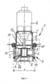
- FIG 2 is the gas control valve 1 with one to the off figure 1 identical direct pressure regulator comprising the housing 2 as a cartridge 7, the valve body 3, the valve seat 4, the springs 8 and 10 and the membrane 9 arranged on the valve seat 4.
- a non-gas-tight stepping motor 6 is used, which is fastened to the housing 2 of the gas control valve 1 via an upper housing 2', the stepping motor 6 acting indirectly on the valve body 3 via the axis 5 and the axis 5 acting as an extension rod between the valve body 3 and the stepping motor 6 is used.
- a sealing plate 11 is arranged between the stepping motor 6 and the membrane 3, which has a recess 12 in the central area, through which the axis 5 extends.
- the sealing plate 11 is inserted into the case 2 and fixed to the case 2 via the upper case 2' holding the stepping motor 6. As shown in FIG. Due to the present construction, a non-gastight stepping motor 6 can be used, which is at least 30% cheaper than a gas-tight stepping motor.
- Sealing means 13 , 13 ′ are provided on the housing 2 designed as an insert cartridge 7 , which prevent gas from escaping past the gas control valve 1 on the outside.
- the upper housing 2′ has bores on the outside, through which screws, not shown, can be fixed to fix the gas control valve 1 to another component.
- the upper housing 2' is formed as a simple bracket, but fulfills the identical functions.
- a compensation opening 17' is provided in the upper housing 2' for pressure compensation
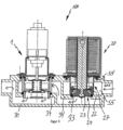
- FIG 3 a gas control unit 100 for controlling the amount of gas to be supplied to a gas burner is shown, the gas control valve 1 designed as a module being made of figure 2 and a gas safety valve 20 designed as a module are arranged in series, with the gas safety valve 20 being located in front of the gas control valve 1 as seen in the direction of flow.
- Both the gas control valve 1 and the gas safety valve 20 are detachably fastened in a gas valve housing 30 .
- both valves 1 and 20 are designed as modules, so that they do not place any demands on the gas valve housing 30 apart from the fastening means to be provided for fastening. Only room 55 has to meet increased requirements.
- the gas safety valve 20 is designed as a coaxial double safety valve, so that a single gas safety valve 20 is sufficient to ensure the legally required protection against gas leakage.
- the gas safety valve 20 also has an insert cartridge 27 which is arranged in the gas valve 30 and is formed by the lower section of the housing 22 .
- the manner in which such gas safety valves 20 are operated electronically in order to release the valve body 23 from the valve seats 24 and to ensure double protection via the springs is known from the prior art.
- the use of an insert cartridge 27 on the gas safety valve 20 according to the invention makes it possible for this to be plugged into the gas valve housing 30 in a modular manner and attached thereto.
- Attaching additional screws can be provided as fastening means, or threads that engage in one another can be provided directly on the insert cartridge 27 and the gas valve housing 30 .
- the insert cartridge 27 is sealed twice on the gas valve housing 30 by sealing means 33 and 33'. The gas thus enters the insert cartridge 27 from the right side, as shown by the arrow, and when the valve body 23 is detached from the valve seat 24, it is pressed by the gas pressure provided to the gas control valve 1, which it passes through the valve seat to the gas outlet.
- the gas valve housing 30 has corresponding webs 34, 34' which accommodate the modules and on which the insert cartridges 7 and 27 rest in a sealing manner.
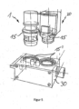
- figure 4 shows a perspective schematic view of a fan housing 40 on which fastening means 15' are provided in the form of threads into which the gas control valve 1 and the gas safety valve 20 can be screwed.
- figure 5 shows a perspective view of a gas valve housing 30, with modules of a gas control valve 1 and a module provided for attachment at the top Gas safety valve 20, the gas control valve 1 and the gas safety valve 20 being provided with threads 15 which can be screwed into the corresponding thread 15' on the gas valve housing 30.
Landscapes
- Engineering & Computer Science (AREA)
- General Engineering & Computer Science (AREA)
- Mechanical Engineering (AREA)
- Chemical & Material Sciences (AREA)
- Combustion & Propulsion (AREA)
- Physics & Mathematics (AREA)
- Electromagnetism (AREA)
- Feeding And Controlling Fuel (AREA)
- Valve Housings (AREA)
- Electrically Driven Valve-Operating Means (AREA)
- Lift Valve (AREA)
Description
- Die Erfindung betrifft eine Gasregeleinheit in modularer Bauweise, insbesondere zur Regelung der einem Gasbrenner zuzuführenden Gasmenge, sowie ein in seiner Gesamtheit als Modul ausgebildetes Gasregelventil, das in einer derartigen, modular aufgebauten Gasregeleinheit verwendbar ist.
- Aus dem Stand der Technik sind verschiedene Gasregelventile und Gassicherheitsventile zur Verwendung bei Gas-/Luft-Mischeinheiten und insbesondere bei Gasbrennern bekannt. Die europäische Patentanmeldung
EP 0 834 695 A1 offenbart eine Mischvorrichtung für Gasbrenner, in deren Gehäuse Elektromagnetisch betriebene Schließelemente angeordnet sind, um einen Gasfluss zu einem Ventilsitz zu öffnen und zu schließen. Der Ventilsitz selbst ist dabei durch das Gehäuse bzw. daran einteilig ausgebildete Abschnitte der Mischvorrichtung gebildet. Die in diesem Stand der Technik verwendeten Flachventile sind zum Regeln der Gasmenge ungeeignet, da sich ihre Einstellung im Wesentlichen auf die Stellungen "Auf" und "Zu" beschränken. Durch die Verwendung von Teilen des Gehäuses der Mischvorrichtung als Ventilsitz muss dieses zumindest in diesem Bereich mit einer besonderen Oberfläche ausgebildet sein, um die Abdichtung gewährleisten zu können. Dies erfordert nach der Fertigung des Gehäuses üblicherweise aufwendige Nacharbeiten am Ventilsitz. - Die
US 5,642,756 A ,DE 195 34 285 A1 undUS 2007/0205384 A1 offenbaren weitere Ventillösungen aus unterschiedlichen Anwendungsgebieten. - Ferner ist aus der
EP 2 048 439 A1 bekannt, einen Gasregler mit Ventilkörper in ein Radialgebläsegehäuse zu integrieren, und den Ventilsitz des ganzen Reglers unmittelbar an einem im Inneren liegenden Gehäuseteil anzuordnen. - Bei vielen der bekannten Lösungen ist jedoch nachteilig, dass die Gasregelventile beziehungsweise Gassicherheitsventile speziell auf eine bestimmte Gehäuseform der Mischvorrichtung oder des Gebläses abgestimmt sein müssen und jeweils für nur dieses eine Produkt verwendbar sind.
- Ausgehend von dieser Problematik ist es die Aufgabe der Erfindung, eine Gasregeleinheit und ein darin verwendbares Gasregelventil bereitzustellen, die in verschiedenen Gehäusetypen, insbesondere von Mischvorrichtungen oder Gebläsen, einsetzbar sind. Ferner ist Aufgabe der Erfindung, die Montagezeit der für die Gasregelung zuständigen Einheiten zu reduzieren und die für die Funktion und Dichtheit durchzuführenden Tests zu verkürzen.
- Diese Aufgaben werden gelöst durch ein Gasregelventil nach Anspruch 1 sowie eine Gasregeleinheit nach Anspruch 7.
- Ein erfindungsgemäßes Gasregelventil umfasst ein Gehäuse mit Gaseinlass, ein in dem Gehäuse gehaltenen, in einer ersten und zweiten axialen Richtung beweglich angeordneten Ventilkörper, einen Ventilsitz, mindestens eine erste Feder, die in der ersten axialen Richtung auf den Ventilkörper wirkt, eine in axialer Richtung bewegliche, mit dem Ventilkörper mittelbar in Eingriff stehende Achse, ein auf die Achse wirkender Antrieb, der diese und somit den Ventilkörper in vordefinierten Längenabschnitten in axialer Richtung zum Öffnen und Schließen des Gasregelventil bewegt, wobei der Antrieb ein elektronisch angesteuerter Schrittmotor und das Gasregelventil in seiner Gesamtheit als auswechselbares Modul ausgebildet ist. Das Gasregelventil muss hierbei keinerlei Sicherheitsfunktionen erfüllen.
- Unter "auswechselbares Modul" ist zu verstehen, dass das Gasregelventil als eigenständige Komponente ausgebildet und mit weiteren Komponenten kombinierbar ist. Durch die Ausbildung als Modul kann das Gasregelventil über eine passende Schnittstelle an beliebigen, dafür vorgesehenen Bauteilen angebracht und wieder entfernt werden. Die Achse ist vorzugsweise metallisch.
- In einer bevorzugten Ausführung ist zumindest ein Teil des Gehäuses als eine Einsatzkartusche ausgebildet, wodurch das als Modul ausgebildete Gasregelventil kompakt aufgebaut und in Gehäusen von Gebläsevorrichtungen oder Gas-Luft-Mischvorrichtungen eingesteckt oder eingeschraubt werden kann. Hierbei ist günstig, wenn an dem als Einsatzkartusche ausgebildeten Gehäuse außenseitig ein Gewinde, ein Flansch oder ein vergleichbares lösbares Befestigungsmittel vorgesehen ist. Auch ist vorteilhaft, dass in eine derartige Einsatzkartusche die den Gasfluss beziehungsweise die Gasmenge bestimmenden Bauteile aufgenommen sind, und sich somit, wenn die Kartusche in dem entsprechenden Gehäuse eingeschraubt ist, im Gasströmungsweg befinden. Die "Einsatzkartusche" ist hierbei definiert als ein Gehäuseteil, der geeignet ist, in ein anderes Bauteil eingesetzt zu werden, ohne dass an dem anderen Bauteil neben einer entsprechenden Formanpassung weitergehende konstruktionsbedingte Maßnahmen bereitgestellt sein müssen.
- Im Gegensatz zu der im Stand der Technik
EP 0 834 695 A1 verwendeten pneumatischen Regelung der Gasmenge und den in den SchriftenUS 5,642,756 A ,DE 195 34 285 A1 undUS 2007/0205384 A1 offenbarten Lösungen, ist es erfindungsgemäß vorgesehen, als Antrieb des Gasregelventils ein elektronisch angesteuerten Schrittmotor zu verwenden. Über den Schrittmotor und die sich in erster axialer Richtung versetzende Achse wird eine ansteigende Kraft auf den Ventilkörper ausgeübt, welche der Federkraft der ersten Feder entgegenwirkt, bis sich der Ventilkörper von dem Ventilsitz löst und den Gasfluss freigibt. - In einer vorteilhaften Ausführung ist das Gasregelventil mit einem Direktdruckregler ausgebildet, wobei der Ventilkörper im Zentrum von einer Membran gehalten ist und der Gaseinlass in axialer Richtung zwischen Membran und Ventilsitz erfolgt sodass ein Gasdruck in der ersten axialen Richtung gegen die Membran und in der zweiten, entgegengesetzten axialen Richtung gegen den Ventilkörper bzw. gegen sich in radial nach außen erstreckende Abschnitte des Ventilkörpers wirkt. Der Ventilkörper befindet sich somit in einem Kräftegleichgewicht, beeinflusst durch die Federkraft der ersten Feder, den Außendruck sowie den Gasdruck gegen die den Ventilkörper haltende Membran in eine erste axiale Richtung und den Gasdruck und die Kraft des Antriebs auf den Ventilkörper in eine zweite axiale Richtung.
- Hierdurch wird gewährleistet, dass nur ein kleiner Hub des Antriebs, in bevorzugter Ausführung des Schrittmotors, nötig ist, um den Ventilkörper in vordefinierter Weise von dem Ventilsitz in die zweite axiale Richtung zu lösen und somit eine vordefinierte Gasmenge pro Zeit freizugeben. Durch die erfindungsgemäße Ausbildung des Direktdruckreglers mit Kräftegleichgewicht ist ermöglicht, größere Durchtrittsdurchmesser von 15 - 35mm, vorzugsweise 15 - 25mm für den Gasweg bereitzustellen, sodass der notwendige Hub des Ventilkörpers vom Ventilsitz drastisch reduziert ist und 3 - 8mm, vorzugsweise 3 - 5 mm nicht übersteigt. Bei Gasregelventilen gemäß dem Stand der Technik ist ein Hub von 10mm nötig. Durch die Verringerung des notwendigen Hubs in die axiale Richtung kann der die diese Axialbewegung erzeugende Schrittmotor in einer sehr einfachen und vergleichsweise kostengünstigen Ausbildung vorliegen, was zu einer erheblichen Reduzierung der Gesamtkosten des Gasregelventils in modularer Bauweise führt. Auch der Durchmesser des Gehäuses und die Größe des freigegebenen Gaswegs des Gasregelventils sind durch die Bereitstellung des Kräftegleichgewichts gegenüber aus dem Stand der Technik bekannten Reglern viel größer dimensionierbar, ohne die Regelgenauigkeit negativ zu beeinträchtigen. Als Außendurchmesser des Gehäuses werden erfindungsgemäß eine Größe "c" von 30-50mm, vorzugsweise 30-40mm, als Größe des freigegebenen Gaswegs mit einer Spaltweite "b" von 2 - 5mm bevorzugt.
- Die Bewegung des Ventilkörpers in die zweite axiale Richtung wird erfindungsgemäß ferner noch genauer dadurch geregelt, dass zwischen der Achse und dem Ventilkörper eine zweite Feder angeordnet ist, die in die zweite axiale Richtung auf den Ventilkörper wirkt. Bei Verwendung eines Schrittmotors können dann über einzelne Schritte und Halbschritte die vorbestimmten Öffnungsstellungen des Ventilkörpers elektronisch angesteuert werden. Zur Begünstigung der kompakten Bauweise ist in einer Ausführung vorgesehen, dass die zweite Feder innerhalb des hohl ausgebildeten Ventilkörpers angeordnet ist und sich in axialer Richtung entlang der Achse des Antriebs, beziehungsweise Schrittmotors, erstreckt. In einer vorteilhaften erfindungsgemäßen Ausführung ist der Ventilsitz durch Teile des Gehäuses des Gasregelventils, insbesondere durch Teile der Einsatzkartusche gebildet, sodass auf zusätzliche Bauteile innerhalb des modularen Gasregelventil soweit wie möglich verzichtet und somit die Bauweise vor allem in axialer Richtung kleinstmöglich gestaltet werden kann. In einer vorteilhaften Ausführung ist vorgesehen, dass sich von dem als Einsatzkartusche ausgebildeten Gehäuse des Gasregelventils Abschnitte in radialer Richtung zum Zentrum erstrecken und mit ihrem radial nach innen weisenden Randbereich den Ventilsitz bilden.
- Der Direktdruckregler kann von dem Antrieb, insbesondere dem Schrittmotor, durch eine vorzugsweise metallische Dichtplatte getrennt sein, wobei die Dichtplatte zwischen dem Schrittmotor und dem Membran angeordnet wird. Im zentralen Bereich der Dichtplatte ist eine Aussparung vorgesehen, durch die sich die Achse hindurch erstreckt und eine mittelbare Verbindung zwischen dem Antrieb, insbesondere dem Schrittmotor, und dem Ventilkörper herstellt. Die Dichtplatte dichtet den Direktdruckregler nicht absolut, sondern nur insoweit, wie es die Normen (zum Beispiel: DIN-EN 13611) fordern, wobei im Fehlerfall eine gewisse Gasmenge (weniger 70 Liter/Stunde) über die Aussparung der Dichtplatte entweichen darf. Eine Ausführungsform des Gasregelventils mit Dichtplatte ist dahingehend günstig, dass der verwendete Antrieb, insbesondere Schrittmotor, selbst nicht gasdicht ausgebildet sein muss und somit deutlich kostengünstiger ist.
- Gemäß einem weiteren Aspekt der Erfindung wird das oben dargestellte Gasregelventil zusammen mit einem ebenfalls als Modul ausgebildeten Gassicherheitsventil zu einer Gasregeleinheit in modularer Bauweise, insbesondere zur Regelung der einem Gasbrenner zuzuführenden Gasmenge, kombiniert. Das als Modul ausgebildete Gasregelventil ist hierbei in Reihe mit dem als Modul ausgebildeten Gassicherheitsventil derart angeordnet, dass sich das Gassicherheitsventil in Strömungsrichtung gesehen vor dem Gasregelventil befindet.
- Durch die Verwendung zweier jeweils modular aufgebauter Bauteile ist die Entwicklungszeit reduziert, da jedes Modul nur einmal entwickelt werden muss, später aber in verschiedenen Endprodukten, beispielsweise in Lüftergehäusen, Gasventilgehäusen oder Gas-Luft-Krümmern, verwendet werden können. Ferner kann jedes der Module separat gefertigt und in seiner Funktion getestet werden, wobei die Testvorrichtungen für die modularen Ventile wesentlich kleiner sein können, als diejenigen, die im Stand der Technik für die Gesamtbauteile, z.B. Lüftergehäuse mit daran angeordneten Sicherheitsventilen und einem Gasregelventil, verwendet werden mussten.
- Auch ist an der modularen Bauweise von Vorteil, dass mehrere der jeweiligen als Module gebildeten Gasregelventile und Gassicherheitsventile parallel an den jeweiligen Endprodukte anbringbar sind und somit auf einfache und kostengünstige Weise größere Leistungen und Modulationsbreiten erzielbar sind.
- In einer bevorzugten Ausführung ist für die Gasregeleinheit nur ein einziges Gassicherheitsventil vorgesehen und dieses als Doppel-Sicherheitsventil ausgebildet. Somit kann der Notwendigkeit einer doppelten Abdichtung von im Gasweg angeordneten Bauteilen Rechnung getragen werden, ohne dass der hierfür notwendige Bauraum groß wäre, wie es bei einer Verwendung von zwei separat angeordneten Sicherheitsventilen der Fall wäre. Ferner ist hierbei günstig, das Gassicherheitsventil als Koaxial-Ventil auszubilden, da dieses besonders kompakt baut und die auf dem Bauteil, auf dem die Ventile letztlich angeordnet werden, notwendige Fläche gegenüber den aus dem Stand der Technik bekannten Lösungen geringer ist.
- Neben dem Gasregelventil ist bevorzugt, dass auch das Gassicherheitsventil ein kartuschenartiges Gehäuse mit Mitteln zur lösbaren Befestigung an einem Gasventilgehäuse, Lüftergehäuse oder Krümmer aufweist. Ferner ist in einer vorteilhaften Ausführungsform vorgesehen, dass an den kartuschenartigen Gehäuseteilen der beiden modularen Ventile jeweils außenseitig angeordnete Dichtmittel zur Abdichtung der Module an dem Gasventilgehäuse, Lüftergehäuse oder Krümmer vorgesehen sind. Durch die kartuschenartige Ausbildung der jeweiligen Gehäuse kann dies in Form von kostengünstigen Dichtringen erfolgen, die zwischen dem Gasventilgehäuse, Lüftergehäuse oder Krümmer und dem jeweiligen Modul dichtend eingebracht sind.
- Günstig ist ferner, dass an das Gasventilgehäuse, Lüftergehäuse oder Krümmer hinsichtlich der Materialbeschaffenheit oder Oberfläche keine besonderen Anforderungen nötig sind, da sowohl die Leckagesicherung als auch die Gasregelung ausschließlich über die modularen Gassicherheitsventile und das Gasregelventil erfolgt. Es muss lediglich ein zu den Modulen bzw. kartuschenartigen Gehäusen jeweils passender Aufnahmebereich vorgesehen werden, in den das jeweilige Modul eingesteckt und darin lösbar befestigt wird. In einer besonders einfachen Ausführung weisen die modular gebildeten Ventile und das Gasventilgehäuse, Lüftergehäuse oder der Krümmer jeweils zueinander passende Gewinde auf. Es sind aber auch andere Befestigungsarten wie Flansch-Verschraubungen, Clipverbindungen oder weitere im Stand der Technik bekannte Lösungen möglich.
- Eine kombinierte Einheit aus Gasventilgehäuse, Lüftergehäuse oder Krümmer mit dem als Modul ausgebildeten Gasregelventil und dem als Modul ausgebildeten Gassicherheitsventil ist hinsichtlich seiner Baugröße um mindestens 20% verkleinert, als bisher verwendete entsprechende Einheiten, bei denen Gasregelventile und Gassicherheitsventile in nicht modularer Bauweise eingesetzt wurden. Bei einer Verwendung eines Doppel-Sicherheitsventils in koaxialer Bauweise, wobei ein zweites Sicherheitsventil eingespart wird, ist die Gesamtbaugrößenreduzierung im Vergleich zu aus dem Stand der Technik bekannten Lösungen mindestens 40%.
- Andere vorteilhafte Ausbildungen der Erfindung sind in den Unteransprüchen gekennzeichnet, beziehungsweise werden nachstehend zusammen mit der Beschreibung der bevorzugten Ausführung der Erfindung anhand der Figuren näher dargestellt. Es zeigen:
-
Fig.1 eine seitliche Schnittansicht eines Gasregelventils mit gasdichtem Antrieb; -
Fig.2 eine seitliche Schnittansicht eines Gasregelventils mit nichtgasdichtem Antrieb; -
Fig.3 eine Gasregeleinheit mit Gasregelventil mit koaxial Doppel-Sicherheitsventil; -
Fig.4 eine perspektivische Darstellung eines Lüfters mit einsetzbarem modular ausgebildetem Gasregelventil und Gassicherheitsventil; und -
Fig.5 eine perspektivische Ansicht Gasventilgehäuses mit einsetzbarem modular ausgebildetem Gasregelventil und Gassicherheitsventil. - Die Figuren zeigen die zum Verständnis der Erfindung notwendigen Bauteile beispielhaft schematisch, wobei gleiche Bauteile mit jeweils gleichen Bezugszeichen gekennzeichnet sind.
- In
Figur 1 ist ein Gasregelventil 1 mit einem als Schrittmotor 6 ausgebildeten Antrieb, der auf einem Direktdruckregler angeordnet ist, gezeigt. Das Gasregelventil 1 ist in seiner Gesamtheit als auswechselbares Modul ausgebildet, wobei das Gehäuse 2 der Teil des Moduls ist, der in das jeweilige Endprodukt (z.B. Gasventilgehäuse, Lüftergehäuse, Krümmer eingesteckt und darin fixiert wird. Das Gehäuse 2 ist hierfür als Kartusche 7 gebildet, die im Betrieb im Bereich des Gasstroms angeordnet ist und die die Gasmenge pro Zeit regelnden Bauteile aufnimmt. Ein hohl ausgebildeter Ventilkörper 3 ist in dem kartuschenartigen Gehäuse 2 von einer Membran 9 gehalten, wobei die Membran 9 an dem Gehäuse 2 befestigt ist und eine flächige Abgrenzung zu dem Schrittmotor 6 bildet. Eine Ausgleichsöffnung 17 ermöglicht den Druckausgleich im Bereich oberhalb der Membran 9. Das Gehäuse 2 weist einen sich in radialer Richtung zum Zentrum hin erstreckenden Abschnitt 14 auf, der den Ventilsitz 4 für den Ventilkörper 3 bildet. Zwischen Gehäuse 2 und Ventilkörper 3 ist eine erste Feder 8 angeordnet, die in der ersten axialen Richtung Y1 auf den Ventilkörper 3 wirkt, und diesen gegen den Ventilsitz 4 drückt. Der Gaseinlass in das Gasregelventil 1 erfolgt in axialer Richtung zwischen der Membran 9 und dem Ventilsitz 4, sodass der Gasdruck in der ersten axialen Richtung Y1 gegen die Membran 9 und in der zweiten, entgegengesetzten axialen Richtung Y2 gegen den Ventilkörper 3 beziehungsweise gegen an dem Ventilkörper 3 sich in radialer Richtung nach außen hin erstreckende Abschnitte wirkt. Die Krafteinwirkung durch den Gasdruck auf den Ventilkörper 3 erfolgt somit in beide axialen Richtungen Y1, Y2 und ist in der Summe im Wesentlichen gleich Null. Der Schrittmotor 6 weist eine Achse 5 auf, über die eine Kraft in die zweite axiale Richtung Y2 mittelbar auf den Ventilkörper 3 aufgebracht werden kann, um diesen zu versetzen. In der gezeigten Ausführung ist innerhalb des Ventilkörpers 3 eine zweite, sich in axialer Richtung erstreckender Feder 10 geordnet, auf welche die Achse 5 des Schrittmotors 6 in die zweite axiale Richtung Y2 wirkt, um den Ventilkörper 3 vom Ventilsitz 4 zu lösen. Die Krafteinwirkung durch den Schrittmotor 6 über die zweite Feder 10 erfolgt gegen die Kraft der ersten Feder 8 und den außerhalb des Gasregelventils 1 herrschenden Außendruck. Der Ventilkörper 3 befindet sich über die Kräfte des Gasdrucks, und der Federkräfte in einem Kräftegleichgewicht, sodass jeder Axialversatz der Achse 5 in der zweiten axialen Richtung Y2 unmittelbar einen entsprechenden Hub des Ventilkörpers 3 vom Ventilsitz 4 bedeutet. Durch dieses Kräftegleichgewicht ist es möglich, den Durchmesser des Gehäuses 2, des Ventilkörpers 3 und des durch den Ventilkörper 3 freigegebenen Gaswegs (Ventilspalt mit Öffnungsweite b) größer auszubilden, sodass der absolut notwendige Hub in axialer Richtung des Ventilkörpers 3 vom Ventilsitz auf 3mm begrenzt werden kann. Das Gehäuse 2 weist einen Außendurchmesser von 30-50mm, der Ventilkörper einen Außendurchmesser von 15-25mm und der für den Gasweg am Ventilsitz 4 freigegebene umlaufende Ventilspalt eine Öffnungsweite von 3 - 5mm auf. - In
Figur 2 ist das Gasregelventil 1 mit einem zu dem ausFigur 1 identischem Direktdruckregler umfassend das Gehäuse 2 als Kartusche 7, den Ventilkörper 3, den Ventilsitz 4, die Federn 8 und 10 sowie die am Ventilsitz 4 angeordnete Membran 9. Im Unterschied zu der Ausführung gemäßFigur 1 ist ein nicht-gasdichter Schrittmotor 6 verwendet, der über ein Obergehäuse 2' auf dem Gehäuse 2 des Gasregelventils 1 befestigt ist, wobei der Schrittmotor 6 über die Achse 5 mittelbar auf den Ventilkörper 3 wirkt und die Achse 5 als Verlängerungsstab zwischen dem Ventilkörper 3 und dem Schrittmotor 6 dient. Zwischen dem Schrittmotor 6 und dem Membran 3 ist eine Dichtplatte 11 angeordnet, die im zentralen Mittelbereich eine Aussparung 12 aufweist, durch die sich die Achse 5 hindurch erstreckt. Zwar kann über die Aussparung 12 eine gewisse Gasmenge entweichen, diese ist jedoch so gering, dass die international gültigen Normen eingehalten werden. Die Dichtplatte 11 ist in das Gehäuse 2 eingesetzt und über das den Schrittmotor 6 haltende Obergehäuse 2' an dem Gehäuse 2 befestigt. Durch die vorliegende Konstruktion kann ein nicht-gasdichter Schrittmotor 6 verwendet werden, der gegenüber einem gasdichten Schrittmotor um mindestens 30% kostengünstiger ist. An dem als Einsatzkartusche 7 ausgebildeten Gehäuse 2 sind Dichtmittel 13, 13' vorgesehen, die einen Gasaustritt außen an dem Gasregelventil 1 vorbei verhindern. Das Obergehäuse 2' weist außenseitige Bohrungen auf, durch die nicht dargestellte Schrauben zur Festlegung des Gasregelventil 1an einem weiteren Bauteil fixierbar sind. In einer nicht dargestellten, alternativen Ausführung ist das Obergehäuse 2' als einfacher Bügel ausgeformt, erfüllt aber die identischen Funktionen. Zum Druckausgleich ist in dem Obergehäuse 2' eine Ausgleichsöffnung 17' vorgesehen - In
Figur 3 ist eine Gasregeleinheit 100 zur Regelung der einem Gasbrenner zuzuführenden Gasmenge dargestellt, wobei das als Modul ausgebildete Gasregelventil 1 ausFigur 2 und ein als Modul ausgebildetes Gassicherheitsventil 20 in Reihe angeordnet sind, wobei sich in Strömungsrichtung gesehen das Gassicherheitsventil 20 vor dem Gasregelventil 1 befindet. Sowohl das Gasregelventil 1 als auch das Gassicherheitsventil 20 sind in einem Gasventilgehäuse 30 lösbar befestigt. Gegenüber den aus dem Stand der Technik vorbekannten Lösungen sind beide Ventile 1 und 20 als Module ausgebildet, sodass sie bis auf die zur Befestigung vorzusehenden Befestigungsmittel keine Anforderungen an das Gasventilgehäuse 30 stellen. Es muss nur der Raum 55 erhöhte Anforderungen erfüllen. Das Gassicherheitsventil 20 ist als koaxiales Doppel-Sicherheitsventil ausgebildet, sodass ein einziges Gassicherheitsventil 20 ausreicht, um die gesetzlich vorgeschriebene Absicherung gegen Gasaustritt zu gewährleisten. Auch das Gassicherheitsventil 20 weist eine in dem Gasventil 30 angeordnete Einsatzkartusche 27 auf, die durch den unteren Abschnitt des Gehäuses 22 gebildet ist. Die Art und Weise, derartige Gassicherheitsventile 20 elektronisch zu betreiben, um den Ventilkörper 23 von den Ventilsitzen 24 zu lösen und die Doppelabsicherung über die Federn zu gewährleisten ist aus dem Stand der Technik bekannt. Die erfindungsgemäße Verwendung einer Einsatzkartusche 27 am Gassicherheitsventil 20 ermöglicht, dass dieses modular in das Gasventilgehäuse 30 eingesteckt und daran befestigt werden kann. Als Befestigungsmittel kann vorgesehen sein, zusätzliche Schrauben anzubringen, oder unmittelbar an der Einsatzkartusche 27 und dem Gasventilgehäuse 30 ineinandergreifende Gewinde vorzusehen. Ferner wird die Einsatzkartusche 27 zweifach über Dichtmittel 33 und 33' am Gasventilgehäuse 30 abgedichtet. Das Gas tritt somit wie durch den Pfeil dargestellt von rechts seitlich in die Einsatzkartusche 27 ein und wird bei einem vom Ventilsitz 24 gelösten Ventilkörper 23 durch den bereitgestellten Gasdruck zu dem Gasregelventil 1 gedrückt, welches es über den Ventilsitz zum Gasauslass passiert. Zur Definition des Gaswegs weist das Gasventilgehäuse 30 entsprechende die Module aufnehmende Stege 34, 34' auf, an denen die Einsatzkartuschen 7 und 27 jeweils dichtend anliegen. -
Figur 4 zeigt in perspektivisch schematischer Ansicht ein Lüftergehäuse 40, an dem Befestigungsmittel 15' in Form von Gewinden vorgesehen sind, in die das Gasregelventil 1 und das Gassicherheitsventil 20 einschraubbar sind. -
Figur 5 zeigt eine perspektivische Ansicht eines Gasventilgehäuses 30, mit zur oberseitigen Befestigung vorgesehenen Modulen eines Gasregelventiles 1 und eines Gassicherheitsventils 20, wobei das Gasregelventil 1 und das Gassicherheitsventil 20 mit Gewinden 15 versehen sind, die in das entsprechende Gewinde 15' am Gasventilgehäuse 30 einschraubbar sind.
Claims (13)
- Gasregelventil umfassend- ein Gehäuse (2) mit Gaseinlass,- einen in dem Gehäuse (2) gehaltenen, in einer ersten (Y1) und zweiten axialen Richtung (Y2) beweglich angeordneten Ventilkörper (3),- einen Ventilsitz (4),- mindestens eine erste Feder (8), die in der ersten axialen Richtung (Y1) auf den Ventilkörper (3) wirkt,- eine in axialer Richtung (Y1, Y2) bewegliche, mit dem Ventilkörper (3) mittelbar in Eingriff stehende Achse (5),- ein auf die Achse (5) wirkender Antrieb (6), der diese und somit den Ventilkörper (3) in vordefinierten Längenabschnitten in axialer Richtung (Y1, Y2) zum Öffnen und Schließen des Gasregelventils (1) bewegt, wobei- das Gasregelventil (1) in seiner Gesamtheit als auswechselbares Modul ausgebildet ist, wobei- der Ventilkörper (3) von einer Membran (9) gehalten ist und der Gaseinlass in axialer Richtung zwischen Membran (9) und Ventilsitz (4) erfolgt, so dass ein Gasdruck in der ersten axialen Richtung (Y1) gegen die Membran (9) und in der zweiten, entgegengesetzten axialen Richtung (Y2) gegen den Ventilkörper (3) wirkt, wobei- zwischen der Achse (5) und dem Ventilkörper (3) eine zweite Feder (10) angeordnet ist, die in die zweite axiale Richtung (Y2) unmittelbar auf den Ventilkörper (3) wirkt, und wobei die zweite Feder (10) innerhalb des hohl ausgebildeten Ventilkörpers (3) angeordnet ist.
- Gasregelventil nach Anspruch 1, dadurch gekennzeichnet, dass zumindest ein Teil des Gehäuses (2) als eine Einsatzkartusche (7) ausgebildet ist.
- Gasregelventil nach zumindest einem der vorigen Ansprüche, dadurch gekennzeichnet, dass der Antrieb (6) ein elektronisch angesteuerter Schrittmotor ist.
- Gasregelventil nach dem vorigen Anspruch, dadurch gekennzeichnet, dass ein nicht-gasdichter Schrittmotor (6) verwendet wird.
- Gasregelventil nach zumindest einem der vorigen Ansprüche, dadurch gekennzeichnet, dass der Ventilsitz (4) durch Teile des Gehäuses (2) i des Gasregelventils (1) gebildet ist.
- Gasregelventil nach zumindest einem der vorigen Ansprüche 3 bis 5, dadurch gekennzeichnet, dass zwischen dem Schrittmotor (6) und der Membran (3) eine Dichtplatte (11) mit Aussparung (12) vorgesehen ist, wobei sich die Achse (5) durch die Aussparung (12) hindurch erstreckt.
- Gasregeleinheit in modularer Bauweise, insbesondere zur Regelung der einem Gasbrenner zuzuführenden Gasmenge, umfassend ein als Modul ausgebildetes Gasregelventil (1) nach mindestens einem der Ansprüche 1 bis 6 und mindestens ein als Modul ausgebildetes Gassicherheitsventil (20).
- Gasregeleinheit nach dem vorigen Anspruch, wobei das als Modul ausgebildete Gasregelventil (1) und das als Modul ausgebildete Gassicherheitsventil (20) in Reihe angeordnet sind und das mindestens eine Gassicherheitsventil (20) in Gasströmungsrichtung vor dem Gasregelventil (1) angeordnet ist.
- Gasregeleinheit nach zumindest einem der vorigen Ansprüche 7 bis 8, dadurch gekennzeichnet, dass das als Modul ausgebildete Gassicherheitsventil (20) ein Gehäuse (22), einen Ventilkörper und mindestens einen Ventilsitz (24) aufweist, wobei der mindestens eine Ventilsitz (24) durch Teile des Gehäuses (22) gebildet ist.
- Gasregeleinheit nach zumindest einem der vorigen Ansprüche 7 bis 9, dadurch gekennzeichnet, dass ein einziges Gassicherheitsventil (20) vorgesehen und dieses als Doppel-Sicherheitsventil ausgebildet ist.
- Gasregeleinheit nach zumindest einem der vorigen Ansprüche 7 bis 10, dadurch gekennzeichnet, dass das als Modul ausgebildete Gasregelventil (1) und das als Modul ausgebildete Gassicherheitsventil (20) jeweils kartuschenartige Gehäuseteile (7, 27) mit Mitteln (15) zur lösbaren Befestigung an einem Gasventilgehäuse (30), Lüftergehäuse (40) oder Krümmer aufweisen.
- Gasregeleinheit nach dem vorigen Anspruch, dadurch gekennzeichnet, dass an den kartuschenartigen Gehäuseteilen (7, 27) jeweils außenseitig angeordnete Dichtmittel (13, 13', 33, 33') zur Abdichtung der Module an dem Gasventilgehäuse (30), Lüftergehäuse (40) oder Krümmer vorgesehen sind.
- Gasventitgehäuse (30), Lüftergehäuse (40) oder Krümmer umfassend eine Gasregeleinheit (100) nach einem der vorigen Ansprüche 7 bis 12.
Applications Claiming Priority (2)
| Application Number | Priority Date | Filing Date | Title |
|---|---|---|---|
| DE102012102645A DE102012102645A1 (de) | 2012-03-27 | 2012-03-27 | Gasregeleinheit in modularer Bauweise und Gasregelventil |
| PCT/EP2013/053926 WO2013143799A1 (de) | 2012-03-27 | 2013-02-27 | Gasregeleinheit in modularer bauweise und gasregelventil |
Publications (3)
| Publication Number | Publication Date |
|---|---|
| EP2802781A1 EP2802781A1 (de) | 2014-11-19 |
| EP2802781B1 EP2802781B1 (de) | 2016-11-16 |
| EP2802781B2 true EP2802781B2 (de) | 2023-08-09 |
Family
ID=47845945
Family Applications (1)
| Application Number | Title | Priority Date | Filing Date |
|---|---|---|---|
| EP13708725.0A Active EP2802781B2 (de) | 2012-03-27 | 2013-02-27 | Gasregeleinheit in modularer bauweise und gasregelventil |
Country Status (5)
| Country | Link |
|---|---|
| US (1) | US9416888B2 (de) |
| EP (1) | EP2802781B2 (de) |
| CN (1) | CN104246239B (de) |
| DE (1) | DE102012102645A1 (de) |
| WO (1) | WO2013143799A1 (de) |
Families Citing this family (15)
| Publication number | Priority date | Publication date | Assignee | Title |
|---|---|---|---|---|
| DE102012102646A1 (de) * | 2012-03-27 | 2013-10-02 | Ebm-Papst Landshut Gmbh | Gasregelventil |
| DE102013102354A1 (de) * | 2013-03-08 | 2014-09-11 | Ebm-Papst Landshut Gmbh | Pneumatische Gasregeleinheit in modularer Bauweise und modulares Gasregelventil |
| US9910447B2 (en) * | 2015-03-10 | 2018-03-06 | Fratelli Pettinaroli S.P.A. | Automatic balancing valve |
| CN105626874A (zh) * | 2016-03-16 | 2016-06-01 | 芜湖美的厨卫电器制造有限公司 | 燃气比例阀 |
| US11118701B2 (en) * | 2017-03-03 | 2021-09-14 | The Coca-Cola Company | Flow control module |
| DE102018200301A1 (de) * | 2018-01-10 | 2019-07-11 | Zf Friedrichshafen Ag | Ventileinrichtung |
| DE102018102866A1 (de) * | 2018-02-08 | 2019-08-08 | Ebm-Papst Landshut Gmbh | Ventilüberwachungssystem für ein koaxiales Doppelsicherheitsventil |
| DE202019104590U1 (de) | 2019-08-21 | 2019-09-12 | Ebm-Papst Landshut Gmbh | Gasregeleinheit und Gasgebläse |
| US11499726B2 (en) * | 2019-09-17 | 2022-11-15 | Emerson Electric Co. | Coaxial gas valve assemblies including electronically controlled solenoids |
| CN111075984B (zh) * | 2020-01-14 | 2022-02-22 | 嘉兴市大宇机电有限公司 | 一种校零空燃比例电磁阀 |
| CN111089194B (zh) * | 2020-01-14 | 2021-10-01 | 嘉兴市大宇机电有限公司 | 一种模块化多功能调节空燃比例电磁阀 |
| DE102021124568A1 (de) | 2021-09-22 | 2023-03-23 | Ebm-Papst Landshut Gmbh | Antrieb |
| CN113803479B (zh) * | 2021-09-30 | 2025-08-12 | 芜湖泰和管业股份有限公司 | 一种燃气管道用简易电机阀 |
| CN115614518B (zh) * | 2022-10-31 | 2026-02-03 | 芜湖美的智能厨电制造有限公司 | 比例阀的阀体、比例阀和燃气设备 |
| CN116519753B (zh) * | 2023-06-28 | 2023-08-25 | 北京燕山时代仪表有限公司 | 一种可燃气体报警器气体浓度检测组件 |
Citations (16)
| Publication number | Priority date | Publication date | Assignee | Title |
|---|---|---|---|---|
| JPS6131778A (ja) † | 1984-07-23 | 1986-02-14 | Matsushita Electric Ind Co Ltd | ガス制御装置 |
| US4643394A (en) † | 1984-06-12 | 1987-02-17 | C.K.D. Controls Co., Ltd. | Gas solenoid valve |
| EP0757200A2 (de) † | 1995-07-12 | 1997-02-05 | Karl Dungs GmbH & Co. | Doppel-Sicherheitsmagnetventil |
| US6047718A (en) † | 1999-04-01 | 2000-04-11 | Emersonelectric Co. | Solenoid valve having coaxial armatures in a single coil design |
| EP1039229A2 (de) † | 1999-03-23 | 2000-09-27 | Concentric Controls Limited | Gasgreät |
| EP1084357A2 (de) † | 1998-06-12 | 2001-03-21 | Karl Dungs GmbH & Co. | Doppelsicherheitsventil |
| JP2001317652A (ja) † | 2000-05-01 | 2001-11-16 | Time Engineering Co Ltd | 電磁比例弁 |
| DE10205857C1 (de) † | 2002-02-13 | 2003-09-18 | Dungs Karl Gmbh & Co Kg | Doppelabsperr- und Regelarmatur |
| DE10306001A1 (de) † | 2002-02-13 | 2003-11-20 | Dungs Karl Gmbh & Co Kg | Doppelabsperrarmatur |
| EP1382907A1 (de) † | 2002-07-12 | 2004-01-21 | G. Kromschröder Aktiengesellschaft | Vorrichtung zum Regeln des Gasstromes zu einem Brenner |
| JP2005023952A (ja) † | 2003-06-30 | 2005-01-27 | Rinnai Corp | 閉止機能付比例制御弁 |
| DE10330067A1 (de) † | 2003-07-03 | 2005-02-10 | Chun-Cheng Huang | Sperrventil mit Motorantrieb |
| WO2005088194A1 (en) † | 2004-03-18 | 2005-09-22 | Sit La Precisa, S.P.A. | A valve unit for cotrolling the supply of a fuel gas, particularly for cooking hobs and the like |
| WO2006003684A1 (en) † | 2004-07-02 | 2006-01-12 | Sit La Precisa S.P.A. | Multi-function valve for controlling the feed of a combustible gas to a burner apparatus |
| JP2006057820A (ja) † | 2004-08-24 | 2006-03-02 | Rinnai Corp | 電磁比例弁 |
| CN102072344A (zh) † | 2010-11-25 | 2011-05-25 | 宁波方太厨具有限公司 | 一种燃气热水器中比例阀的控制装置 |
Family Cites Families (10)
| Publication number | Priority date | Publication date | Assignee | Title |
|---|---|---|---|---|
| US4706929A (en) * | 1986-12-08 | 1987-11-17 | Stanley G. Flagg & Co., Inc. | Pneumatically operated valve with manual override and lockout |
| US4898203A (en) * | 1988-09-22 | 1990-02-06 | Jacob Kobelt | Valve apparatus |
| US5125622A (en) * | 1991-05-22 | 1992-06-30 | Amcast Industrial Corporation | Cylinder valve connection |
| DE19534285A1 (de) * | 1995-09-15 | 1997-03-20 | Bosch Gmbh Robert | Elektromagnetisch betätigbares pneumatisches Wegeventil |
| US5642756A (en) * | 1996-02-29 | 1997-07-01 | Bio-Chem Valve Inc. | Valve manifold assembly |
| DE69604070T2 (de) | 1996-10-03 | 2000-02-17 | Siabs Industry S.R.L., Legnano | Vorrichtung zum Zuführen eines Gas/Luft-Gemisches zu einem Brenner, insbesondere für Heizungsanlagen |
| JP2004125113A (ja) * | 2002-10-04 | 2004-04-22 | Matsushita Electric Ind Co Ltd | 遮断弁及びこの遮断弁が組み込まれた遮断弁ブロック |
| US20070205384A1 (en) * | 2006-03-02 | 2007-09-06 | Smc Kabushiki Kaisha | Flow Rate Control Apparatus |
| EP2048439B1 (de) | 2007-10-12 | 2014-06-18 | ebm-papst Landshut GmbH | Radialgebläse mit integriertem Regelventil |
| US8939173B2 (en) * | 2010-07-14 | 2015-01-27 | Mac Valves, Inc. | Stepper motor operated balanced flow control valve |
-
2012
- 2012-03-27 DE DE102012102645A patent/DE102012102645A1/de not_active Withdrawn
-
2013
- 2013-02-27 EP EP13708725.0A patent/EP2802781B2/de active Active
- 2013-02-27 US US14/387,784 patent/US9416888B2/en active Active
- 2013-02-27 WO PCT/EP2013/053926 patent/WO2013143799A1/de not_active Ceased
- 2013-02-27 CN CN201380013781.1A patent/CN104246239B/zh active Active
Patent Citations (16)
| Publication number | Priority date | Publication date | Assignee | Title |
|---|---|---|---|---|
| US4643394A (en) † | 1984-06-12 | 1987-02-17 | C.K.D. Controls Co., Ltd. | Gas solenoid valve |
| JPS6131778A (ja) † | 1984-07-23 | 1986-02-14 | Matsushita Electric Ind Co Ltd | ガス制御装置 |
| EP0757200A2 (de) † | 1995-07-12 | 1997-02-05 | Karl Dungs GmbH & Co. | Doppel-Sicherheitsmagnetventil |
| EP1084357A2 (de) † | 1998-06-12 | 2001-03-21 | Karl Dungs GmbH & Co. | Doppelsicherheitsventil |
| EP1039229A2 (de) † | 1999-03-23 | 2000-09-27 | Concentric Controls Limited | Gasgreät |
| US6047718A (en) † | 1999-04-01 | 2000-04-11 | Emersonelectric Co. | Solenoid valve having coaxial armatures in a single coil design |
| JP2001317652A (ja) † | 2000-05-01 | 2001-11-16 | Time Engineering Co Ltd | 電磁比例弁 |
| DE10306001A1 (de) † | 2002-02-13 | 2003-11-20 | Dungs Karl Gmbh & Co Kg | Doppelabsperrarmatur |
| DE10205857C1 (de) † | 2002-02-13 | 2003-09-18 | Dungs Karl Gmbh & Co Kg | Doppelabsperr- und Regelarmatur |
| EP1382907A1 (de) † | 2002-07-12 | 2004-01-21 | G. Kromschröder Aktiengesellschaft | Vorrichtung zum Regeln des Gasstromes zu einem Brenner |
| JP2005023952A (ja) † | 2003-06-30 | 2005-01-27 | Rinnai Corp | 閉止機能付比例制御弁 |
| DE10330067A1 (de) † | 2003-07-03 | 2005-02-10 | Chun-Cheng Huang | Sperrventil mit Motorantrieb |
| WO2005088194A1 (en) † | 2004-03-18 | 2005-09-22 | Sit La Precisa, S.P.A. | A valve unit for cotrolling the supply of a fuel gas, particularly for cooking hobs and the like |
| WO2006003684A1 (en) † | 2004-07-02 | 2006-01-12 | Sit La Precisa S.P.A. | Multi-function valve for controlling the feed of a combustible gas to a burner apparatus |
| JP2006057820A (ja) † | 2004-08-24 | 2006-03-02 | Rinnai Corp | 電磁比例弁 |
| CN102072344A (zh) † | 2010-11-25 | 2011-05-25 | 宁波方太厨具有限公司 | 一种燃气热水器中比例阀的控制装置 |
Also Published As
| Publication number | Publication date |
|---|---|
| CN104246239A (zh) | 2014-12-24 |
| EP2802781A1 (de) | 2014-11-19 |
| DE102012102645A1 (de) | 2013-10-02 |
| US20150053287A1 (en) | 2015-02-26 |
| EP2802781B1 (de) | 2016-11-16 |
| CN104246239B (zh) | 2017-03-01 |
| WO2013143799A1 (de) | 2013-10-03 |
| US9416888B2 (en) | 2016-08-16 |
Similar Documents
| Publication | Publication Date | Title |
|---|---|---|
| EP2802781B2 (de) | Gasregeleinheit in modularer bauweise und gasregelventil | |
| EP2769124B1 (de) | Gasregelventil | |
| EP2965008B1 (de) | Gasregeleinheit in modularer bauweise | |
| EP2271969B1 (de) | Armaturenkombination zur regelung der durchflussmenge oder des differenzdruckes | |
| DE60117219T2 (de) | Elektromagnetisches Ventil | |
| DE10084851B3 (de) | Regulierventil für konstanten Durchfluß | |
| EP1275039A1 (de) | Gasdruckregler | |
| DE10322585B4 (de) | Ventilbaukastensysteme | |
| DE69919438T2 (de) | Pneumatisches Patronenventil | |
| EP4314611A1 (de) | Einstellbares drosselelement | |
| DE102007013505A1 (de) | Armaturenkombination zur Regelung der Durchflussmenge oder des Differenzdruckes | |
| DE202018006471U1 (de) | Ventilzufuhrvorrichtung | |
| DE4025414C2 (de) | ||
| DE202019104590U1 (de) | Gasregeleinheit und Gasgebläse | |
| EP2184522B1 (de) | Stelleinrichtung für ein pneumatisches Regelventil | |
| DE1475906C3 (de) | GasreduzierventiL | |
| EP3527862A1 (de) | Ventil mit einer einrichtung zur voreinstellung des strömungskanalquerschnittes | |
| DE9101263U1 (de) | Gasdruckregler | |
| DE20317221U1 (de) | Gasdruckregler | |
| DE9106301U1 (de) | Einstelleinrichtung | |
| EP3163166B1 (de) | Heizgerätevorrichtung und verfahren mit einer heizgerätevorrichtung | |
| EP0561018B1 (de) | Membrangesteuerter Gasdruckregler mit einstellbarer Drossel | |
| EP4357875A2 (de) | Thermostatkartusche | |
| DE1301284B (de) | Gasventil | |
| DE102022202370A1 (de) | Druckreduzierventil |
Legal Events
| Date | Code | Title | Description |
|---|---|---|---|
| PUAI | Public reference made under article 153(3) epc to a published international application that has entered the european phase |
Free format text: ORIGINAL CODE: 0009012 |
|
| 17P | Request for examination filed |
Effective date: 20140812 |
|
| AK | Designated contracting states |
Kind code of ref document: A1 Designated state(s): AL AT BE BG CH CY CZ DE DK EE ES FI FR GB GR HR HU IE IS IT LI LT LU LV MC MK MT NL NO PL PT RO RS SE SI SK SM TR |
|
| DAX | Request for extension of the european patent (deleted) | ||
| 17Q | First examination report despatched |
Effective date: 20160216 |
|
| GRAP | Despatch of communication of intention to grant a patent |
Free format text: ORIGINAL CODE: EPIDOSNIGR1 |
|
| RIN1 | Information on inventor provided before grant (corrected) |
Inventor name: VROLIJK, ENNO Inventor name: KEBER, ROLAND Inventor name: KLINK, HANS-JOACHIM |
|
| INTG | Intention to grant announced |
Effective date: 20160816 |
|
| GRAS | Grant fee paid |
Free format text: ORIGINAL CODE: EPIDOSNIGR3 |
|
| GRAA | (expected) grant |
Free format text: ORIGINAL CODE: 0009210 |
|
| AK | Designated contracting states |
Kind code of ref document: B1 Designated state(s): AL AT BE BG CH CY CZ DE DK EE ES FI FR GB GR HR HU IE IS IT LI LT LU LV MC MK MT NL NO PL PT RO RS SE SI SK SM TR |
|
| REG | Reference to a national code |
Ref country code: GB Ref legal event code: FG4D Free format text: NOT ENGLISH |
|
| REG | Reference to a national code |
Ref country code: CH Ref legal event code: EP |
|
| REG | Reference to a national code |
Ref country code: IE Ref legal event code: FG4D Free format text: LANGUAGE OF EP DOCUMENT: GERMAN |
|
| REG | Reference to a national code |
Ref country code: AT Ref legal event code: REF Ref document number: 846235 Country of ref document: AT Kind code of ref document: T Effective date: 20161215 |
|
| REG | Reference to a national code |
Ref country code: DE Ref legal event code: R096 Ref document number: 502013005377 Country of ref document: DE |
|
| REG | Reference to a national code |
Ref country code: DE Ref legal event code: R096 Ref document number: 502013005377 Country of ref document: DE |
|
| REG | Reference to a national code |
Ref country code: NL Ref legal event code: FP |
|
| REG | Reference to a national code |
Ref country code: FR Ref legal event code: PLFP Year of fee payment: 5 |
|
| PG25 | Lapsed in a contracting state [announced via postgrant information from national office to epo] |
Ref country code: LV Free format text: LAPSE BECAUSE OF FAILURE TO SUBMIT A TRANSLATION OF THE DESCRIPTION OR TO PAY THE FEE WITHIN THE PRESCRIBED TIME-LIMIT Effective date: 20161116 |
|
| REG | Reference to a national code |
Ref country code: LT Ref legal event code: MG4D |
|
| PG25 | Lapsed in a contracting state [announced via postgrant information from national office to epo] |
Ref country code: GR Free format text: LAPSE BECAUSE OF FAILURE TO SUBMIT A TRANSLATION OF THE DESCRIPTION OR TO PAY THE FEE WITHIN THE PRESCRIBED TIME-LIMIT Effective date: 20170217 Ref country code: SE Free format text: LAPSE BECAUSE OF FAILURE TO SUBMIT A TRANSLATION OF THE DESCRIPTION OR TO PAY THE FEE WITHIN THE PRESCRIBED TIME-LIMIT Effective date: 20161116 Ref country code: LT Free format text: LAPSE BECAUSE OF FAILURE TO SUBMIT A TRANSLATION OF THE DESCRIPTION OR TO PAY THE FEE WITHIN THE PRESCRIBED TIME-LIMIT Effective date: 20161116 Ref country code: NO Free format text: LAPSE BECAUSE OF FAILURE TO SUBMIT A TRANSLATION OF THE DESCRIPTION OR TO PAY THE FEE WITHIN THE PRESCRIBED TIME-LIMIT Effective date: 20170216 |
|
| PG25 | Lapsed in a contracting state [announced via postgrant information from national office to epo] |
Ref country code: HR Free format text: LAPSE BECAUSE OF FAILURE TO SUBMIT A TRANSLATION OF THE DESCRIPTION OR TO PAY THE FEE WITHIN THE PRESCRIBED TIME-LIMIT Effective date: 20161116 Ref country code: BE Free format text: LAPSE BECAUSE OF NON-PAYMENT OF DUE FEES Effective date: 20170228 Ref country code: FI Free format text: LAPSE BECAUSE OF FAILURE TO SUBMIT A TRANSLATION OF THE DESCRIPTION OR TO PAY THE FEE WITHIN THE PRESCRIBED TIME-LIMIT Effective date: 20161116 Ref country code: RS Free format text: LAPSE BECAUSE OF FAILURE TO SUBMIT A TRANSLATION OF THE DESCRIPTION OR TO PAY THE FEE WITHIN THE PRESCRIBED TIME-LIMIT Effective date: 20161116 Ref country code: PT Free format text: LAPSE BECAUSE OF FAILURE TO SUBMIT A TRANSLATION OF THE DESCRIPTION OR TO PAY THE FEE WITHIN THE PRESCRIBED TIME-LIMIT Effective date: 20170316 Ref country code: PL Free format text: LAPSE BECAUSE OF FAILURE TO SUBMIT A TRANSLATION OF THE DESCRIPTION OR TO PAY THE FEE WITHIN THE PRESCRIBED TIME-LIMIT Effective date: 20161116 |
|
| PG25 | Lapsed in a contracting state [announced via postgrant information from national office to epo] |
Ref country code: EE Free format text: LAPSE BECAUSE OF FAILURE TO SUBMIT A TRANSLATION OF THE DESCRIPTION OR TO PAY THE FEE WITHIN THE PRESCRIBED TIME-LIMIT Effective date: 20161116 Ref country code: DK Free format text: LAPSE BECAUSE OF FAILURE TO SUBMIT A TRANSLATION OF THE DESCRIPTION OR TO PAY THE FEE WITHIN THE PRESCRIBED TIME-LIMIT Effective date: 20161116 Ref country code: SK Free format text: LAPSE BECAUSE OF FAILURE TO SUBMIT A TRANSLATION OF THE DESCRIPTION OR TO PAY THE FEE WITHIN THE PRESCRIBED TIME-LIMIT Effective date: 20161116 Ref country code: RO Free format text: LAPSE BECAUSE OF FAILURE TO SUBMIT A TRANSLATION OF THE DESCRIPTION OR TO PAY THE FEE WITHIN THE PRESCRIBED TIME-LIMIT Effective date: 20161116 Ref country code: CZ Free format text: LAPSE BECAUSE OF FAILURE TO SUBMIT A TRANSLATION OF THE DESCRIPTION OR TO PAY THE FEE WITHIN THE PRESCRIBED TIME-LIMIT Effective date: 20161116 |
|
| REG | Reference to a national code |
Ref country code: DE Ref legal event code: R026 Ref document number: 502013005377 Country of ref document: DE |
|
| PLBI | Opposition filed |
Free format text: ORIGINAL CODE: 0009260 |
|
| PG25 | Lapsed in a contracting state [announced via postgrant information from national office to epo] |
Ref country code: SM Free format text: LAPSE BECAUSE OF FAILURE TO SUBMIT A TRANSLATION OF THE DESCRIPTION OR TO PAY THE FEE WITHIN THE PRESCRIBED TIME-LIMIT Effective date: 20161116 Ref country code: BG Free format text: LAPSE BECAUSE OF FAILURE TO SUBMIT A TRANSLATION OF THE DESCRIPTION OR TO PAY THE FEE WITHIN THE PRESCRIBED TIME-LIMIT Effective date: 20170216 |
|
| 26 | Opposition filed |
Opponent name: SIT S.P.A. Effective date: 20170807 |
|
| PLAX | Notice of opposition and request to file observation + time limit sent |
Free format text: ORIGINAL CODE: EPIDOSNOBS2 |
|
| PG25 | Lapsed in a contracting state [announced via postgrant information from national office to epo] |
Ref country code: MC Free format text: LAPSE BECAUSE OF FAILURE TO SUBMIT A TRANSLATION OF THE DESCRIPTION OR TO PAY THE FEE WITHIN THE PRESCRIBED TIME-LIMIT Effective date: 20161116 |
|
| REG | Reference to a national code |
Ref country code: CH Ref legal event code: PL |
|
| PG25 | Lapsed in a contracting state [announced via postgrant information from national office to epo] |
Ref country code: LI Free format text: LAPSE BECAUSE OF NON-PAYMENT OF DUE FEES Effective date: 20170228 Ref country code: CH Free format text: LAPSE BECAUSE OF NON-PAYMENT OF DUE FEES Effective date: 20170228 |
|
| REG | Reference to a national code |
Ref country code: IE Ref legal event code: MM4A |
|
| PG25 | Lapsed in a contracting state [announced via postgrant information from national office to epo] |
Ref country code: SI Free format text: LAPSE BECAUSE OF FAILURE TO SUBMIT A TRANSLATION OF THE DESCRIPTION OR TO PAY THE FEE WITHIN THE PRESCRIBED TIME-LIMIT Effective date: 20161116 |
|
| PG25 | Lapsed in a contracting state [announced via postgrant information from national office to epo] |
Ref country code: LU Free format text: LAPSE BECAUSE OF NON-PAYMENT OF DUE FEES Effective date: 20170227 |
|
| PLBB | Reply of patent proprietor to notice(s) of opposition received |
Free format text: ORIGINAL CODE: EPIDOSNOBS3 |
|
| REG | Reference to a national code |
Ref country code: BE Ref legal event code: MM Effective date: 20170228 |
|
| REG | Reference to a national code |
Ref country code: FR Ref legal event code: PLFP Year of fee payment: 6 |
|
| PG25 | Lapsed in a contracting state [announced via postgrant information from national office to epo] |
Ref country code: IE Free format text: LAPSE BECAUSE OF NON-PAYMENT OF DUE FEES Effective date: 20170227 |
|
| PG25 | Lapsed in a contracting state [announced via postgrant information from national office to epo] |
Ref country code: MT Free format text: LAPSE BECAUSE OF FAILURE TO SUBMIT A TRANSLATION OF THE DESCRIPTION OR TO PAY THE FEE WITHIN THE PRESCRIBED TIME-LIMIT Effective date: 20161116 |
|
| REG | Reference to a national code |
Ref country code: AT Ref legal event code: MM01 Ref document number: 846235 Country of ref document: AT Kind code of ref document: T Effective date: 20180227 |
|
| PG25 | Lapsed in a contracting state [announced via postgrant information from national office to epo] |
Ref country code: AT Free format text: LAPSE BECAUSE OF NON-PAYMENT OF DUE FEES Effective date: 20180227 |
|
| APBM | Appeal reference recorded |
Free format text: ORIGINAL CODE: EPIDOSNREFNO |
|
| APBP | Date of receipt of notice of appeal recorded |
Free format text: ORIGINAL CODE: EPIDOSNNOA2O |
|
| APAH | Appeal reference modified |
Free format text: ORIGINAL CODE: EPIDOSCREFNO |
|
| APBM | Appeal reference recorded |
Free format text: ORIGINAL CODE: EPIDOSNREFNO |
|
| APBP | Date of receipt of notice of appeal recorded |
Free format text: ORIGINAL CODE: EPIDOSNNOA2O |
|
| PG25 | Lapsed in a contracting state [announced via postgrant information from national office to epo] |
Ref country code: HU Free format text: LAPSE BECAUSE OF FAILURE TO SUBMIT A TRANSLATION OF THE DESCRIPTION OR TO PAY THE FEE WITHIN THE PRESCRIBED TIME-LIMIT; INVALID AB INITIO Effective date: 20130227 |
|
| APBQ | Date of receipt of statement of grounds of appeal recorded |
Free format text: ORIGINAL CODE: EPIDOSNNOA3O |
|
| PG25 | Lapsed in a contracting state [announced via postgrant information from national office to epo] |
Ref country code: ES Free format text: LAPSE BECAUSE OF NON-PAYMENT OF DUE FEES Effective date: 20161116 |
|
| APBQ | Date of receipt of statement of grounds of appeal recorded |
Free format text: ORIGINAL CODE: EPIDOSNNOA3O |
|
| PG25 | Lapsed in a contracting state [announced via postgrant information from national office to epo] |
Ref country code: CY Free format text: LAPSE BECAUSE OF FAILURE TO SUBMIT A TRANSLATION OF THE DESCRIPTION OR TO PAY THE FEE WITHIN THE PRESCRIBED TIME-LIMIT Effective date: 20161116 |
|
| PG25 | Lapsed in a contracting state [announced via postgrant information from national office to epo] |
Ref country code: MK Free format text: LAPSE BECAUSE OF FAILURE TO SUBMIT A TRANSLATION OF THE DESCRIPTION OR TO PAY THE FEE WITHIN THE PRESCRIBED TIME-LIMIT Effective date: 20161116 |
|
| PG25 | Lapsed in a contracting state [announced via postgrant information from national office to epo] |
Ref country code: AL Free format text: LAPSE BECAUSE OF FAILURE TO SUBMIT A TRANSLATION OF THE DESCRIPTION OR TO PAY THE FEE WITHIN THE PRESCRIBED TIME-LIMIT Effective date: 20161116 Ref country code: IS Free format text: LAPSE BECAUSE OF FAILURE TO SUBMIT A TRANSLATION OF THE DESCRIPTION OR TO PAY THE FEE WITHIN THE PRESCRIBED TIME-LIMIT Effective date: 20170316 |
|
| APBU | Appeal procedure closed |
Free format text: ORIGINAL CODE: EPIDOSNNOA9O |
|
| P01 | Opt-out of the competence of the unified patent court (upc) registered |
Effective date: 20230521 |
|
| PUAH | Patent maintained in amended form |
Free format text: ORIGINAL CODE: 0009272 |
|
| STAA | Information on the status of an ep patent application or granted ep patent |
Free format text: STATUS: PATENT MAINTAINED AS AMENDED |
|
| 27A | Patent maintained in amended form |
Effective date: 20230809 |
|
| AK | Designated contracting states |
Kind code of ref document: B2 Designated state(s): AL AT BE BG CH CY CZ DE DK EE ES FI FR GB GR HR HU IE IS IT LI LT LU LV MC MK MT NL NO PL PT RO RS SE SI SK SM TR |
|
| REG | Reference to a national code |
Ref country code: DE Ref legal event code: R102 Ref document number: 502013005377 Country of ref document: DE |
|
| REG | Reference to a national code |
Ref country code: NL Ref legal event code: FP |
|
| PGFP | Annual fee paid to national office [announced via postgrant information from national office to epo] |
Ref country code: DE Payment date: 20250218 Year of fee payment: 13 |
|
| PGFP | Annual fee paid to national office [announced via postgrant information from national office to epo] |
Ref country code: FR Payment date: 20250220 Year of fee payment: 13 |
|
| PGFP | Annual fee paid to national office [announced via postgrant information from national office to epo] |
Ref country code: IT Payment date: 20250228 Year of fee payment: 13 Ref country code: GB Payment date: 20250220 Year of fee payment: 13 |
|
| PGFP | Annual fee paid to national office [announced via postgrant information from national office to epo] |
Ref country code: TR Payment date: 20250218 Year of fee payment: 13 |
|
| PGFP | Annual fee paid to national office [announced via postgrant information from national office to epo] |
Ref country code: NL Payment date: 20260218 Year of fee payment: 14 |