EP2802781B2 - Régulateur de pression de gaz modulaire et soupape de régulation de gaz - Google Patents
Régulateur de pression de gaz modulaire et soupape de régulation de gaz Download PDFInfo
- Publication number
- EP2802781B2 EP2802781B2 EP13708725.0A EP13708725A EP2802781B2 EP 2802781 B2 EP2802781 B2 EP 2802781B2 EP 13708725 A EP13708725 A EP 13708725A EP 2802781 B2 EP2802781 B2 EP 2802781B2
- Authority
- EP
- European Patent Office
- Prior art keywords
- gas
- valve
- housing
- valve body
- axial direction
- Prior art date
- Legal status (The legal status is an assumption and is not a legal conclusion. Google has not performed a legal analysis and makes no representation as to the accuracy of the status listed.)
- Active
Links
- 230000001105 regulatory effect Effects 0.000 title claims description 3
- 238000007789 sealing Methods 0.000 claims description 18
- 239000012528 membrane Substances 0.000 claims description 13
- 238000011144 upstream manufacturing Methods 0.000 claims 1
- 230000001276 controlling effect Effects 0.000 description 4
- 230000002349 favourable effect Effects 0.000 description 4
- 239000007795 chemical reaction product Substances 0.000 description 3
- 238000010276 construction Methods 0.000 description 2
- 238000011161 development Methods 0.000 description 2
- 230000018109 developmental process Effects 0.000 description 2
- 230000002411 adverse Effects 0.000 description 1
- 230000001419 dependent effect Effects 0.000 description 1
- 238000009434 installation Methods 0.000 description 1
- 239000000463 material Substances 0.000 description 1
- 239000002184 metal Substances 0.000 description 1
- 239000000047 product Substances 0.000 description 1
- 238000005549 size reduction Methods 0.000 description 1
Images

Classifications
-
- F—MECHANICAL ENGINEERING; LIGHTING; HEATING; WEAPONS; BLASTING
- F16—ENGINEERING ELEMENTS AND UNITS; GENERAL MEASURES FOR PRODUCING AND MAINTAINING EFFECTIVE FUNCTIONING OF MACHINES OR INSTALLATIONS; THERMAL INSULATION IN GENERAL
- F16K—VALVES; TAPS; COCKS; ACTUATING-FLOATS; DEVICES FOR VENTING OR AERATING
- F16K27/00—Construction of housing; Use of materials therefor
-
- F—MECHANICAL ENGINEERING; LIGHTING; HEATING; WEAPONS; BLASTING
- F16—ENGINEERING ELEMENTS AND UNITS; GENERAL MEASURES FOR PRODUCING AND MAINTAINING EFFECTIVE FUNCTIONING OF MACHINES OR INSTALLATIONS; THERMAL INSULATION IN GENERAL
- F16K—VALVES; TAPS; COCKS; ACTUATING-FLOATS; DEVICES FOR VENTING OR AERATING
- F16K31/00—Actuating devices; Operating means; Releasing devices
- F16K31/02—Actuating devices; Operating means; Releasing devices electric; magnetic
- F16K31/04—Actuating devices; Operating means; Releasing devices electric; magnetic using a motor
-
- F—MECHANICAL ENGINEERING; LIGHTING; HEATING; WEAPONS; BLASTING
- F16—ENGINEERING ELEMENTS AND UNITS; GENERAL MEASURES FOR PRODUCING AND MAINTAINING EFFECTIVE FUNCTIONING OF MACHINES OR INSTALLATIONS; THERMAL INSULATION IN GENERAL
- F16K—VALVES; TAPS; COCKS; ACTUATING-FLOATS; DEVICES FOR VENTING OR AERATING
- F16K27/00—Construction of housing; Use of materials therefor
- F16K27/02—Construction of housing; Use of materials therefor of lift valves
- F16K27/029—Electromagnetically actuated valves
-
- F—MECHANICAL ENGINEERING; LIGHTING; HEATING; WEAPONS; BLASTING
- F16—ENGINEERING ELEMENTS AND UNITS; GENERAL MEASURES FOR PRODUCING AND MAINTAINING EFFECTIVE FUNCTIONING OF MACHINES OR INSTALLATIONS; THERMAL INSULATION IN GENERAL
- F16K—VALVES; TAPS; COCKS; ACTUATING-FLOATS; DEVICES FOR VENTING OR AERATING
- F16K39/00—Devices for relieving the pressure on the sealing faces
-
- F—MECHANICAL ENGINEERING; LIGHTING; HEATING; WEAPONS; BLASTING
- F23—COMBUSTION APPARATUS; COMBUSTION PROCESSES
- F23N—REGULATING OR CONTROLLING COMBUSTION
- F23N1/00—Regulating fuel supply
- F23N1/005—Regulating fuel supply using electrical or electromechanical means
-
- F—MECHANICAL ENGINEERING; LIGHTING; HEATING; WEAPONS; BLASTING
- F23—COMBUSTION APPARATUS; COMBUSTION PROCESSES
- F23N—REGULATING OR CONTROLLING COMBUSTION
- F23N2235/00—Valves, nozzles or pumps
- F23N2235/02—Air or combustion gas valves or dampers
-
- F—MECHANICAL ENGINEERING; LIGHTING; HEATING; WEAPONS; BLASTING
- F23—COMBUSTION APPARATUS; COMBUSTION PROCESSES
- F23N—REGULATING OR CONTROLLING COMBUSTION
- F23N2235/00—Valves, nozzles or pumps
- F23N2235/12—Fuel valves
- F23N2235/14—Fuel valves electromagnetically operated
-
- F—MECHANICAL ENGINEERING; LIGHTING; HEATING; WEAPONS; BLASTING
- F23—COMBUSTION APPARATUS; COMBUSTION PROCESSES
- F23N—REGULATING OR CONTROLLING COMBUSTION
- F23N2235/00—Valves, nozzles or pumps
- F23N2235/12—Fuel valves
- F23N2235/18—Groups of two or more valves
-
- F—MECHANICAL ENGINEERING; LIGHTING; HEATING; WEAPONS; BLASTING
- F23—COMBUSTION APPARATUS; COMBUSTION PROCESSES
- F23N—REGULATING OR CONTROLLING COMBUSTION
- F23N2235/00—Valves, nozzles or pumps
- F23N2235/12—Fuel valves
- F23N2235/24—Valve details
-
- Y—GENERAL TAGGING OF NEW TECHNOLOGICAL DEVELOPMENTS; GENERAL TAGGING OF CROSS-SECTIONAL TECHNOLOGIES SPANNING OVER SEVERAL SECTIONS OF THE IPC; TECHNICAL SUBJECTS COVERED BY FORMER USPC CROSS-REFERENCE ART COLLECTIONS [XRACs] AND DIGESTS
- Y10—TECHNICAL SUBJECTS COVERED BY FORMER USPC
- Y10T—TECHNICAL SUBJECTS COVERED BY FORMER US CLASSIFICATION
- Y10T137/00—Fluid handling
- Y10T137/8593—Systems
- Y10T137/87917—Flow path with serial valves and/or closures
Definitions
- the invention relates to a gas control unit of modular design, in particular for controlling the amount of gas to be supplied to a gas burner, and to a gas control valve designed in its entirety as a module, which can be used in such a modular gas control unit.
- gas control valves or gas safety valves have to be specially matched to a specific housing shape of the mixing device or the blower and can only be used for this one product.
- the object of the invention to provide a gas control unit and a gas control valve that can be used in it, which can be used in different housing types, in particular of mixing devices or blowers. Furthermore, the object of the invention is to reduce the assembly time of the units responsible for the gas regulation and to shorten the tests to be carried out for the function and tightness.
- a gas control valve comprises a housing with a gas inlet, a valve body held in the housing and arranged to be movable in a first and second axial direction, a valve seat, at least one first spring which acts on the valve body in the first axial direction, a spring which is movable in the axial direction , with the valve body indirectly engaged axle, a drive acting on the axle, which moves this and thus the valve body in predefined length sections in the axial direction to open and close the gas control valve, the drive being an electronically controlled stepping motor and the gas control valve in its entirety is designed as a replaceable module.
- the gas control valve does not have to fulfill any safety functions.
- Replaceable module means that the gas control valve is designed as an independent component and can be combined with other components. Due to the design as a module, the gas control valve can be attached to any components provided for this purpose and removed again via a suitable interface.
- the axis is preferably metallic.
- At least part of the housing is designed as an insert cartridge, whereby the gas control valve designed as a module can be compactly constructed and inserted or screwed into housings of blower devices or gas-air mixing devices. It is favorable here if a thread, a flange or a comparable detachable fastening means is provided on the outside of the housing designed as an insertable cartridge. It is also advantageous that the components determining the gas flow or the gas quantity are accommodated in such an insert cartridge and are therefore located in the gas flow path when the cartridge is screwed into the corresponding housing.
- the “insert cartridge” is defined here as a housing part that is suitable for being inserted into another component without further construction-related measures having to be provided on the other component in addition to a corresponding shape adjustment.
- the gas control valve is designed with a direct pressure regulator, with the valve body being held in the center by a membrane and the gas inlet taking place in the axial direction between the membrane and the valve seat, so that a gas pressure in the first axial direction is against the membrane and in the second, opposite direction axial direction against the valve body or against acts in radially outwardly extending sections of the valve body.
- the valve body is thus in a force equilibrium, influenced by the spring force of the first spring, the external pressure and the gas pressure against the membrane holding the valve body in a first axial direction and the gas pressure and the force of the drive on the valve body in a second axial direction.
- the stepping motor that generates this axial movement can be designed in a very simple and comparatively inexpensive manner, which leads to a considerable reduction in the overall costs of the gas control valve in a modular design.
- the diameter of the housing and the size of the released gas path of the gas control valve can also be dimensioned much larger than controllers known from the prior art due to the provision of the force balance, without adversely affecting the control accuracy.
- a size "c" of 30-50 mm, preferably 30-40 mm is preferred as the outside diameter of the housing, and the size of the released gas path with a gap width "b" of 2-5 mm is preferred.
- the movement of the valve body in the second axial direction is more precisely regulated in that a second spring is arranged between the axle and the valve body, which spring acts on the valve body in the second axial direction.
- a second spring is arranged between the axle and the valve body, which spring acts on the valve body in the second axial direction.
- the predetermined opening positions of the valve body can then be controlled electronically via individual steps and half steps.
- the second spring is arranged inside the hollow valve body and extends in the axial direction along the axis of the drive or stepper motor.
- the valve seat is formed by parts of the housing of the gas control valve, in particular by parts of the insert cartridge, so that additional components within the modular gas control valve can be dispensed with as far as possible and the design can therefore be made as small as possible, especially in the axial direction.
- sections of the housing of the gas control valve, designed as an insert cartridge extend in the radial direction towards the center and form the valve seat with their edge region pointing radially inwards.
- the direct pressure regulator can be separated from the drive, in particular the stepping motor, by a preferably metal sealing plate, with the sealing plate being arranged between the stepping motor and the membrane.
- a recess is provided in the central area of the sealing plate, through which the axis extends and creates an indirect connection between the drive, in particular the stepper motor, and the valve body.
- the sealing plate does not seal the direct pressure regulator absolutely, but only to the extent required by the standards (e.g. DIN-EN 13611), whereby in the event of a fault a certain amount of gas (less than 70 liters/hour) may escape through the recess in the sealing plate.
- An embodiment of the gas control valve with a sealing plate is favorable in that the drive used, in particular a stepper motor, does not itself have to be designed to be gas-tight and is therefore significantly more cost-effective.
- the gas control valve shown above is combined with a gas safety valve, also designed as a module, to form a gas control unit of modular design, in particular for controlling the amount of gas to be supplied to a gas burner.
- the gas control valve designed as a module is arranged in series with the gas safety valve designed as a module in such a way that the gas safety valve is located in front of the gas control valve, viewed in the direction of flow.
- each module only has to be developed once, but can later be used in various end products, for example in fan housings, gas valve housings or gas-air manifolds.
- each of the modules can be manufactured separately and its function tested, whereby the test devices for the modular valves can be significantly smaller than those used in the prior art for the overall components, e.g. fan housing with safety valves and a gas control valve arranged thereon had to.
- Another advantage of the modular design is that several of the respective gas control valves and gas safety valves, which are formed as modules, can be attached in parallel to the respective end products and thus achieve greater performance in a simple and cost-effective manner and modulation widths can be achieved.
- only a single gas safety valve is provided for the gas control unit and this is designed as a double safety valve.
- the need for a double seal of components arranged in the gas path can be taken into account without the installation space required for this being large, as would be the case if two separately arranged safety valves were used.
- the gas safety valve also has a cartridge-like housing with means for detachable attachment to a gas valve housing, fan housing or elbow. Furthermore, in an advantageous embodiment it is provided that on the cartridge-like housing parts of the two modular valves there are sealing means arranged on the outside for sealing the modules on the gas valve housing, fan housing or elbow. Due to the cartridge-like design of the respective housing, this can be done in the form of cost-effective sealing rings, which are introduced in a sealing manner between the gas valve housing, fan housing or manifold and the respective module.
- the gas valve housing, fan housing or manifold in terms of material properties or surface, since both the leakage protection and the gas control are carried out exclusively via the modular gas safety valves and the gas control valve. All that has to be provided is a receiving area that matches the modules or cartridge-like housings and into which the respective module is inserted and detachably fastened therein.
- the modularly formed valves and the gas valve housing, fan housing or manifold each have threads that match one another.
- other types of fastening such as flange screw connections, clip connections or other solutions known from the prior art are also possible.
- a combined unit of gas valve housing, fan housing or manifold with the gas control valve designed as a module and the gas safety valve designed as a module is at least 20% smaller in size than previously used corresponding units in which gas control valves and gas safety valves were used in a non-modular design.
- the overall size reduction is at least 40% compared to solutions known from the prior art.
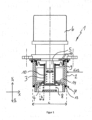
- FIG 1 a gas control valve 1 with a drive designed as a stepper motor 6, which is arranged on a direct pressure regulator, is shown.
- the gas control valve 1 is designed in its entirety as an exchangeable module, with the housing 2 being the part of the module that is inserted into the respective end product (e.g. gas valve housing, fan housing, manifold and fixed therein.
- the housing 2 is designed as a cartridge 7 for this purpose, which is arranged in the area of the gas flow during operation and accommodates the components that regulate the amount of gas per time to the stepping motor 6.
- a compensation opening 17 enables the pressure to be equalized in the region above the diaphragm 9.
- the housing 2 has a section 14 which extends in the radial direction towards the center and forms the valve seat 4 for the valve body 3.
- a first spring 8 is arranged on the valve body 3 and acts on the valve body 3 in the first axial direction Y1 and presses it against the valve seat 4 .
- the gas inlet into the gas control valve 1 takes place in the axial direction between the membrane 9 and the valve seat 4, so that the gas pressure in the first axial direction Y1 against the membrane 9 and in the second, opposite axial direction Y2 against the valve body 3 or against the valve body 3 acts in the radially outwardly extending sections.
- the force exerted by the gas pressure on the valve body 3 thus takes place in both axial directions Y1, Y2 and the sum is essentially equal to zero.
- the stepping motor 6 has an axis 5 via which a force can be applied indirectly to the valve body 3 in the second axial direction Y2 in order to move the latter.
- a second axially extending spring 10 is arranged inside the valve body 3, on which the axis 5 of the stepping motor 6 acts in the second axial direction Y2 in order to release the valve body 3 from the valve seat 4.
- the force applied by the stepping motor 6 via the second spring 10 takes place against the force of the first spring 8 and the external pressure prevailing outside of the gas control valve 1 .
- the valve body 3 is in a force equilibrium via the forces of the gas pressure and the spring forces, so that each axial offset of the axis 5 in the second axial direction Y2 directly means a corresponding lift of the valve body 3 from the valve seat 4 .
- This balance of forces makes it possible to increase the diameter of the housing 2, the valve body 3 and the gas path (valve gap with opening width b) released by the valve body 3, so that the absolutely necessary stroke in the axial direction of the valve body 3 from the valve seat is limited to 3mm can.
- the housing 2 has an outside diameter of 30-50mm
- the valve body has an outside diameter of 15-25mm
- the circumferential valve gap released for the gas path at the valve seat 4 has an opening width of 3-5mm.
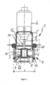
- FIG 2 is the gas control valve 1 with one to the off figure 1 identical direct pressure regulator comprising the housing 2 as a cartridge 7, the valve body 3, the valve seat 4, the springs 8 and 10 and the membrane 9 arranged on the valve seat 4.
- a non-gas-tight stepping motor 6 is used, which is fastened to the housing 2 of the gas control valve 1 via an upper housing 2', the stepping motor 6 acting indirectly on the valve body 3 via the axis 5 and the axis 5 acting as an extension rod between the valve body 3 and the stepping motor 6 is used.
- a sealing plate 11 is arranged between the stepping motor 6 and the membrane 3, which has a recess 12 in the central area, through which the axis 5 extends.
- the sealing plate 11 is inserted into the case 2 and fixed to the case 2 via the upper case 2' holding the stepping motor 6. As shown in FIG. Due to the present construction, a non-gastight stepping motor 6 can be used, which is at least 30% cheaper than a gas-tight stepping motor.
- Sealing means 13 , 13 ′ are provided on the housing 2 designed as an insert cartridge 7 , which prevent gas from escaping past the gas control valve 1 on the outside.
- the upper housing 2′ has bores on the outside, through which screws, not shown, can be fixed to fix the gas control valve 1 to another component.
- the upper housing 2' is formed as a simple bracket, but fulfills the identical functions.
- a compensation opening 17' is provided in the upper housing 2' for pressure compensation
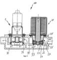
- FIG 3 a gas control unit 100 for controlling the amount of gas to be supplied to a gas burner is shown, the gas control valve 1 designed as a module being made of figure 2 and a gas safety valve 20 designed as a module are arranged in series, with the gas safety valve 20 being located in front of the gas control valve 1 as seen in the direction of flow.
- Both the gas control valve 1 and the gas safety valve 20 are detachably fastened in a gas valve housing 30 .
- both valves 1 and 20 are designed as modules, so that they do not place any demands on the gas valve housing 30 apart from the fastening means to be provided for fastening. Only room 55 has to meet increased requirements.
- the gas safety valve 20 is designed as a coaxial double safety valve, so that a single gas safety valve 20 is sufficient to ensure the legally required protection against gas leakage.
- the gas safety valve 20 also has an insert cartridge 27 which is arranged in the gas valve 30 and is formed by the lower section of the housing 22 .
- the manner in which such gas safety valves 20 are operated electronically in order to release the valve body 23 from the valve seats 24 and to ensure double protection via the springs is known from the prior art.
- the use of an insert cartridge 27 on the gas safety valve 20 according to the invention makes it possible for this to be plugged into the gas valve housing 30 in a modular manner and attached thereto.
- Attaching additional screws can be provided as fastening means, or threads that engage in one another can be provided directly on the insert cartridge 27 and the gas valve housing 30 .
- the insert cartridge 27 is sealed twice on the gas valve housing 30 by sealing means 33 and 33'. The gas thus enters the insert cartridge 27 from the right side, as shown by the arrow, and when the valve body 23 is detached from the valve seat 24, it is pressed by the gas pressure provided to the gas control valve 1, which it passes through the valve seat to the gas outlet.
- the gas valve housing 30 has corresponding webs 34, 34' which accommodate the modules and on which the insert cartridges 7 and 27 rest in a sealing manner.
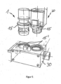
- figure 4 shows a perspective schematic view of a fan housing 40 on which fastening means 15' are provided in the form of threads into which the gas control valve 1 and the gas safety valve 20 can be screwed.
- figure 5 shows a perspective view of a gas valve housing 30, with modules of a gas control valve 1 and a module provided for attachment at the top Gas safety valve 20, the gas control valve 1 and the gas safety valve 20 being provided with threads 15 which can be screwed into the corresponding thread 15' on the gas valve housing 30.
Landscapes
- Engineering & Computer Science (AREA)
- General Engineering & Computer Science (AREA)
- Mechanical Engineering (AREA)
- Chemical & Material Sciences (AREA)
- Combustion & Propulsion (AREA)
- Physics & Mathematics (AREA)
- Electromagnetism (AREA)
- Feeding And Controlling Fuel (AREA)
- Electrically Driven Valve-Operating Means (AREA)
- Valve Housings (AREA)
- Lift Valve (AREA)
Claims (13)
- Soupape de régulation de gaz, comprenant- un boîtier (2) comprenant une arrivée de gaz,- un corps de soupape (3) maintenu dans le boîtier (2), disposé de manière mobile dans une première (Y1) et dans une deuxième direction axiale (Y2),- un siège de soupape (4),- au moins un premier ressort (8), qui agit sur le corps de soupape (3) dans la première direction axiale (Y1),- un axe (5) mobile dans une direction axiale (Y1, Y2), se trouvant en prise indirectement avec le corps de soupape (3),- un entraînement (6) agissant sur l'axe (5), lequel déplace ce dernier et, ce faisant, le corps de soupape (3) dans des sections longitudinales prédéfinies dans une direction axiale (Y1, Y2) afin d'ouvrir et de fermer la soupape de régulation de gaz (1),- la soupape de régulation de gaz (1) étant réalisée dans sa globalité sous la forme d'un module interchangeable,que le corps de soupape (3) est maintenu par une membrane (9), et en ce que l'arrivée de gaz se fait dans une direction axiale entre la membrane (9) et le siège de soupape (4) de sorte qu'une pression de gaz agit dans la première direction axiale (Y1) à l'encontre de la membrane (9) et, dans la deuxième direction axiale (Y2) opposée, à l'encontre du corps de soupape (3),ce qu'est disposé, entre l'axe (5) et le corps de soupape (3), un deuxième ressort (10), qui agit sur le corps de soupape (3) dans la deuxième direction axiale (Y2), que le deuxième ressort (10) est disposé à l'intérieur du corps de soupape (3) réalisé de manière creuse.
- Soupape de régulation de gaz selon la revendication 1, caractérisée en ce qu'au moins une partie du boitier (2) est réalisée sous la forme d'une cartouche à insérer (7).
- Soupape de régulation de gaz selon au moins l'une quelconque des revendications précédentes, caractérisée en ce que l'entraînement (6) est un moteur pas à pas à pilotage électronique.
- Soupape de régulation de gaz selon la revendication précédente, caractérisée en ce qu'un moteur pas à pas (6) non étanche aux gaz est utilisé.
- Soupape de régulation de gaz selon au moins l'une quelconque des revendications précédentes, caractérisée en ce que le siège de soupape (4) est formé par des parties du boîtier (2) de la soupape de régulation de gaz (1).
- Soupape de régulation de gaz selon au moins l'une quelconque des revendications 3 à 5, caractérisée en ce qu'une plaque étanche (11) pourvue d'un évidement (12) est prévue entre le moteur pas à pas (6) et la membrane (3), l'axe (5) s'étendant à travers l'évidement (12).
- Unité de régulation de gaz de type modulaire, servant en particulier à réguler la quantité de gaz à amener au brûleur de gaz, comprenant une soupape de régulation de gaz (1), réalisée sous la forme d'un module, selon au moins l'une quelconque des revendications 1 à 6 et au moins une soupape à gaz de sécurité (20) réalisée sous la forme d'un module.
- Unité de régulation de gaz selon la revendication précédente, la soupape de régulation de gaz (1) réalisée sous la forme d'un module et la soupape à gaz de sécurité (20) réalisée sous la forme d'un module étant disposées de manière alignée, et l'au moins une soupape à gaz de sécurité (20) étant disposée dans la direction d'écoulement de gaz avant la soupape de régulation de gaz (1).
- Unité de régulation de gaz selon au moins l'une quelconque des revendications 7 à 8, caractérisée en ce que la soupape à gaz de sécurité (20) réalisée sous la forme d'un module présente un boîtier (22), un corps de soupape et au moins un siège de soupape (24), l'au moins un siège de soupape (24) étant formé par des parties du boîtier (22).
- Unité de régulation de gaz selon au moins l'une quelconque des revendications 7 à 9, caractérisée en ce qu'une seule soupape à gaz de sécurité (20) est prévue, et en ce que cette dernière est réalisée sous la forme d'une double soupape de sécurité.
- Unité de régulation de gaz selon au moins l'une quelconque des revendications précédentes 7 à 10, caractérisée en ce que la soupape de régulation de gaz (1) réalisée sous la forme d'un module et la soupape à gaz de sécurité (20) réalisée sous la forme d'un module présentent respectivement des parties de boîtier (7, 27) de type cartouche pourvues de moyens (15) destinés à être fixés de manière amovible au niveau d'un boîtier de soupape de gaz (30), d'un boîtier de ventilateur (40) ou d'un collecteur.
- Unité de régulation de gaz selon la revendication précédente, caractérisée en ce que respectivement des moyens étanches (13, 13', 33, 33') disposés côté extérieur servant à étanchéifier les modules au niveau du boîtier de soupape de gaz (30), du boîtier de ventilateur (40) ou du collecteur sont prévus au niveau des parties de boîtier (7, 27) de type cartouche.
- Boîtier de soupape de gaz (30), boîtier de ventilateur (40) ou collecteur comprenant une unité de régulation de gaz (100) selon l'une quelconque des revendications précédentes 7 à 12.
Applications Claiming Priority (2)
| Application Number | Priority Date | Filing Date | Title |
|---|---|---|---|
| DE102012102645A DE102012102645A1 (de) | 2012-03-27 | 2012-03-27 | Gasregeleinheit in modularer Bauweise und Gasregelventil |
| PCT/EP2013/053926 WO2013143799A1 (fr) | 2012-03-27 | 2013-02-27 | Unité de régulation de gaz de conception modulaire et vanne de régulation de gaz |
Publications (3)
| Publication Number | Publication Date |
|---|---|
| EP2802781A1 EP2802781A1 (fr) | 2014-11-19 |
| EP2802781B1 EP2802781B1 (fr) | 2016-11-16 |
| EP2802781B2 true EP2802781B2 (fr) | 2023-08-09 |
Family
ID=47845945
Family Applications (1)
| Application Number | Title | Priority Date | Filing Date |
|---|---|---|---|
| EP13708725.0A Active EP2802781B2 (fr) | 2012-03-27 | 2013-02-27 | Régulateur de pression de gaz modulaire et soupape de régulation de gaz |
Country Status (5)
| Country | Link |
|---|---|
| US (1) | US9416888B2 (fr) |
| EP (1) | EP2802781B2 (fr) |
| CN (1) | CN104246239B (fr) |
| DE (1) | DE102012102645A1 (fr) |
| WO (1) | WO2013143799A1 (fr) |
Families Citing this family (15)
| Publication number | Priority date | Publication date | Assignee | Title |
|---|---|---|---|---|
| DE102012102646A1 (de) * | 2012-03-27 | 2013-10-02 | Ebm-Papst Landshut Gmbh | Gasregelventil |
| DE102013102354A1 (de) * | 2013-03-08 | 2014-09-11 | Ebm-Papst Landshut Gmbh | Pneumatische Gasregeleinheit in modularer Bauweise und modulares Gasregelventil |
| US9910447B2 (en) * | 2015-03-10 | 2018-03-06 | Fratelli Pettinaroli S.P.A. | Automatic balancing valve |
| CN105626874A (zh) * | 2016-03-16 | 2016-06-01 | 芜湖美的厨卫电器制造有限公司 | 燃气比例阀 |
| WO2018160972A1 (fr) * | 2017-03-03 | 2018-09-07 | The Coca-Cola Company | Module de réglage d'écoulement |
| DE102018200301A1 (de) * | 2018-01-10 | 2019-07-11 | Zf Friedrichshafen Ag | Ventileinrichtung |
| DE102018102866A1 (de) * | 2018-02-08 | 2019-08-08 | Ebm-Papst Landshut Gmbh | Ventilüberwachungssystem für ein koaxiales Doppelsicherheitsventil |
| DE202019104590U1 (de) | 2019-08-21 | 2019-09-12 | Ebm-Papst Landshut Gmbh | Gasregeleinheit und Gasgebläse |
| US11499726B2 (en) * | 2019-09-17 | 2022-11-15 | Emerson Electric Co. | Coaxial gas valve assemblies including electronically controlled solenoids |
| CN111089194B (zh) * | 2020-01-14 | 2021-10-01 | 嘉兴市大宇机电有限公司 | 一种模块化多功能调节空燃比例电磁阀 |
| CN111075984B (zh) * | 2020-01-14 | 2022-02-22 | 嘉兴市大宇机电有限公司 | 一种校零空燃比例电磁阀 |
| DE102021124568A1 (de) | 2021-09-22 | 2023-03-23 | Ebm-Papst Landshut Gmbh | Antrieb |
| CN113803479A (zh) * | 2021-09-30 | 2021-12-17 | 芜湖泰和管业股份有限公司 | 一种燃气管道用简易电机阀 |
| CN115614518A (zh) * | 2022-10-31 | 2023-01-17 | 芜湖美的智能厨电制造有限公司 | 比例阀的阀体、比例阀和燃气设备 |
| CN116519753B (zh) * | 2023-06-28 | 2023-08-25 | 北京燕山时代仪表有限公司 | 一种可燃气体报警器气体浓度检测组件 |
Citations (16)
| Publication number | Priority date | Publication date | Assignee | Title |
|---|---|---|---|---|
| JPS6131778A (ja) † | 1984-07-23 | 1986-02-14 | Matsushita Electric Ind Co Ltd | ガス制御装置 |
| US4643394A (en) † | 1984-06-12 | 1987-02-17 | C.K.D. Controls Co., Ltd. | Gas solenoid valve |
| EP0757200A2 (fr) † | 1995-07-12 | 1997-02-05 | Karl Dungs GmbH & Co. | Soupape magnétique de double sureté |
| US6047718A (en) † | 1999-04-01 | 2000-04-11 | Emersonelectric Co. | Solenoid valve having coaxial armatures in a single coil design |
| EP1039229A2 (fr) † | 1999-03-23 | 2000-09-27 | Concentric Controls Limited | Appareils à gaz |
| EP1084357A2 (fr) † | 1998-06-12 | 2001-03-21 | Karl Dungs GmbH & Co. | Double vanne de securite |
| JP2001317652A (ja) † | 2000-05-01 | 2001-11-16 | Time Engineering Co Ltd | 電磁比例弁 |
| DE10205857C1 (de) † | 2002-02-13 | 2003-09-18 | Dungs Karl Gmbh & Co Kg | Doppelabsperr- und Regelarmatur |
| DE10306001A1 (de) † | 2002-02-13 | 2003-11-20 | Dungs Karl Gmbh & Co Kg | Doppelabsperrarmatur |
| EP1382907A1 (fr) † | 2002-07-12 | 2004-01-21 | G. Kromschröder Aktiengesellschaft | Dispositif pour régler le débit de gaz dans un brûleur |
| JP2005023952A (ja) † | 2003-06-30 | 2005-01-27 | Rinnai Corp | 閉止機能付比例制御弁 |
| DE10330067A1 (de) † | 2003-07-03 | 2005-02-10 | Chun-Cheng Huang | Sperrventil mit Motorantrieb |
| WO2005088194A1 (fr) † | 2004-03-18 | 2005-09-22 | Sit La Precisa, S.P.A. | Unite de vanne destinee a controler l'apport de gaz combustible, notamment conçue pour des plaques de cuisson et similaires |
| WO2006003684A1 (fr) † | 2004-07-02 | 2006-01-12 | Sit La Precisa S.P.A. | Soupape multifonction servant a reguler l'alimentation d'un bruleur en gaz combustible |
| JP2006057820A (ja) † | 2004-08-24 | 2006-03-02 | Rinnai Corp | 電磁比例弁 |
| CN102072344A (zh) † | 2010-11-25 | 2011-05-25 | 宁波方太厨具有限公司 | 一种燃气热水器中比例阀的控制装置 |
Family Cites Families (10)
| Publication number | Priority date | Publication date | Assignee | Title |
|---|---|---|---|---|
| US4706929A (en) * | 1986-12-08 | 1987-11-17 | Stanley G. Flagg & Co., Inc. | Pneumatically operated valve with manual override and lockout |
| US4898203A (en) * | 1988-09-22 | 1990-02-06 | Jacob Kobelt | Valve apparatus |
| US5125622A (en) * | 1991-05-22 | 1992-06-30 | Amcast Industrial Corporation | Cylinder valve connection |
| DE19534285A1 (de) | 1995-09-15 | 1997-03-20 | Bosch Gmbh Robert | Elektromagnetisch betätigbares pneumatisches Wegeventil |
| US5642756A (en) | 1996-02-29 | 1997-07-01 | Bio-Chem Valve Inc. | Valve manifold assembly |
| ATE184091T1 (de) | 1996-10-03 | 1999-09-15 | Siabs Industry S R L | Vorrichtung zum zuführen eines gas/luft-gemisches zu einem brenner, insbesondere für heizungsanlagen |
| JP2004125113A (ja) * | 2002-10-04 | 2004-04-22 | Matsushita Electric Ind Co Ltd | 遮断弁及びこの遮断弁が組み込まれた遮断弁ブロック |
| US20070205384A1 (en) * | 2006-03-02 | 2007-09-06 | Smc Kabushiki Kaisha | Flow Rate Control Apparatus |
| EP2048439B1 (fr) | 2007-10-12 | 2014-06-18 | ebm-papst Landshut GmbH | Ventilateur doté d'une soupape de régulation intégrée |
| US8939173B2 (en) * | 2010-07-14 | 2015-01-27 | Mac Valves, Inc. | Stepper motor operated balanced flow control valve |
-
2012
- 2012-03-27 DE DE102012102645A patent/DE102012102645A1/de active Pending
-
2013
- 2013-02-27 WO PCT/EP2013/053926 patent/WO2013143799A1/fr active Application Filing
- 2013-02-27 US US14/387,784 patent/US9416888B2/en active Active
- 2013-02-27 CN CN201380013781.1A patent/CN104246239B/zh active Active
- 2013-02-27 EP EP13708725.0A patent/EP2802781B2/fr active Active
Patent Citations (16)
| Publication number | Priority date | Publication date | Assignee | Title |
|---|---|---|---|---|
| US4643394A (en) † | 1984-06-12 | 1987-02-17 | C.K.D. Controls Co., Ltd. | Gas solenoid valve |
| JPS6131778A (ja) † | 1984-07-23 | 1986-02-14 | Matsushita Electric Ind Co Ltd | ガス制御装置 |
| EP0757200A2 (fr) † | 1995-07-12 | 1997-02-05 | Karl Dungs GmbH & Co. | Soupape magnétique de double sureté |
| EP1084357A2 (fr) † | 1998-06-12 | 2001-03-21 | Karl Dungs GmbH & Co. | Double vanne de securite |
| EP1039229A2 (fr) † | 1999-03-23 | 2000-09-27 | Concentric Controls Limited | Appareils à gaz |
| US6047718A (en) † | 1999-04-01 | 2000-04-11 | Emersonelectric Co. | Solenoid valve having coaxial armatures in a single coil design |
| JP2001317652A (ja) † | 2000-05-01 | 2001-11-16 | Time Engineering Co Ltd | 電磁比例弁 |
| DE10306001A1 (de) † | 2002-02-13 | 2003-11-20 | Dungs Karl Gmbh & Co Kg | Doppelabsperrarmatur |
| DE10205857C1 (de) † | 2002-02-13 | 2003-09-18 | Dungs Karl Gmbh & Co Kg | Doppelabsperr- und Regelarmatur |
| EP1382907A1 (fr) † | 2002-07-12 | 2004-01-21 | G. Kromschröder Aktiengesellschaft | Dispositif pour régler le débit de gaz dans un brûleur |
| JP2005023952A (ja) † | 2003-06-30 | 2005-01-27 | Rinnai Corp | 閉止機能付比例制御弁 |
| DE10330067A1 (de) † | 2003-07-03 | 2005-02-10 | Chun-Cheng Huang | Sperrventil mit Motorantrieb |
| WO2005088194A1 (fr) † | 2004-03-18 | 2005-09-22 | Sit La Precisa, S.P.A. | Unite de vanne destinee a controler l'apport de gaz combustible, notamment conçue pour des plaques de cuisson et similaires |
| WO2006003684A1 (fr) † | 2004-07-02 | 2006-01-12 | Sit La Precisa S.P.A. | Soupape multifonction servant a reguler l'alimentation d'un bruleur en gaz combustible |
| JP2006057820A (ja) † | 2004-08-24 | 2006-03-02 | Rinnai Corp | 電磁比例弁 |
| CN102072344A (zh) † | 2010-11-25 | 2011-05-25 | 宁波方太厨具有限公司 | 一种燃气热水器中比例阀的控制装置 |
Also Published As
| Publication number | Publication date |
|---|---|
| CN104246239A (zh) | 2014-12-24 |
| WO2013143799A1 (fr) | 2013-10-03 |
| CN104246239B (zh) | 2017-03-01 |
| US9416888B2 (en) | 2016-08-16 |
| EP2802781B1 (fr) | 2016-11-16 |
| EP2802781A1 (fr) | 2014-11-19 |
| US20150053287A1 (en) | 2015-02-26 |
| DE102012102645A1 (de) | 2013-10-02 |
Similar Documents
| Publication | Publication Date | Title |
|---|---|---|
| EP2802781B2 (fr) | Régulateur de pression de gaz modulaire et soupape de régulation de gaz | |
| EP2769124B1 (fr) | Vanne de régulation de gaz | |
| EP2271969B1 (fr) | Système de robinetterie permettant de réguler le débit ou la différence de pression | |
| DE60117219T2 (de) | Elektromagnetisches Ventil | |
| EP2965008B1 (fr) | Unité de contrôle de gaz dans conception modulaire | |
| DE10084851B3 (de) | Regulierventil für konstanten Durchfluß | |
| EP1275039A1 (fr) | Regulateur de pression gazeuse | |
| DE10322585B4 (de) | Ventilbaukastensysteme | |
| DE69919438T2 (de) | Pneumatisches Patronenventil | |
| EP0289712B1 (fr) | Régulateur de pression | |
| WO2022207733A1 (fr) | Élément d'étranglement réglable | |
| DE102007013505A1 (de) | Armaturenkombination zur Regelung der Durchflussmenge oder des Differenzdruckes | |
| DE2362905A1 (de) | Regelventil | |
| DE4025414C2 (fr) | ||
| EP3527862A1 (fr) | Soupape pourvue d'un dispositif de présélection de la section du canal d'écoulement | |
| DE202019104590U1 (de) | Gasregeleinheit und Gasgebläse | |
| EP2184522B1 (fr) | Dispositif de réglage pour une soupape de réglage pneumatique | |
| EP3163166B1 (fr) | Appareil de chauffage et procédé comprenant un appareil de chauffage | |
| DE20317221U1 (de) | Gasdruckregler | |
| WO2016000987A1 (fr) | Soupape à pointeau | |
| DE1475906C3 (de) | GasreduzierventiL | |
| EP4357875A2 (fr) | Cartouche thermostatique | |
| EP0561018B1 (fr) | Régulateur de pression de gaz à membrane avec préréglage ajustable | |
| DE102022202370A1 (de) | Druckreduzierventil | |
| DE1301284B (de) | Gasventil |
Legal Events
| Date | Code | Title | Description |
|---|---|---|---|
| PUAI | Public reference made under article 153(3) epc to a published international application that has entered the european phase |
Free format text: ORIGINAL CODE: 0009012 |
|
| 17P | Request for examination filed |
Effective date: 20140812 |
|
| AK | Designated contracting states |
Kind code of ref document: A1 Designated state(s): AL AT BE BG CH CY CZ DE DK EE ES FI FR GB GR HR HU IE IS IT LI LT LU LV MC MK MT NL NO PL PT RO RS SE SI SK SM TR |
|
| DAX | Request for extension of the european patent (deleted) | ||
| 17Q | First examination report despatched |
Effective date: 20160216 |
|
| GRAP | Despatch of communication of intention to grant a patent |
Free format text: ORIGINAL CODE: EPIDOSNIGR1 |
|
| RIN1 | Information on inventor provided before grant (corrected) |
Inventor name: VROLIJK, ENNO Inventor name: KEBER, ROLAND Inventor name: KLINK, HANS-JOACHIM |
|
| INTG | Intention to grant announced |
Effective date: 20160816 |
|
| GRAS | Grant fee paid |
Free format text: ORIGINAL CODE: EPIDOSNIGR3 |
|
| GRAA | (expected) grant |
Free format text: ORIGINAL CODE: 0009210 |
|
| STAA | Information on the status of an ep patent application or granted ep patent |
Free format text: STATUS: THE PATENT HAS BEEN GRANTED |
|
| AK | Designated contracting states |
Kind code of ref document: B1 Designated state(s): AL AT BE BG CH CY CZ DE DK EE ES FI FR GB GR HR HU IE IS IT LI LT LU LV MC MK MT NL NO PL PT RO RS SE SI SK SM TR |
|
| REG | Reference to a national code |
Ref country code: GB Ref legal event code: FG4D Free format text: NOT ENGLISH |
|
| REG | Reference to a national code |
Ref country code: CH Ref legal event code: EP |
|
| REG | Reference to a national code |
Ref country code: IE Ref legal event code: FG4D Free format text: LANGUAGE OF EP DOCUMENT: GERMAN |
|
| REG | Reference to a national code |
Ref country code: AT Ref legal event code: REF Ref document number: 846235 Country of ref document: AT Kind code of ref document: T Effective date: 20161215 |
|
| REG | Reference to a national code |
Ref country code: DE Ref legal event code: R096 Ref document number: 502013005377 Country of ref document: DE |
|
| REG | Reference to a national code |
Ref country code: DE Ref legal event code: R096 Ref document number: 502013005377 Country of ref document: DE |
|
| REG | Reference to a national code |
Ref country code: NL Ref legal event code: FP |
|
| REG | Reference to a national code |
Ref country code: FR Ref legal event code: PLFP Year of fee payment: 5 |
|
| PG25 | Lapsed in a contracting state [announced via postgrant information from national office to epo] |
Ref country code: LV Free format text: LAPSE BECAUSE OF FAILURE TO SUBMIT A TRANSLATION OF THE DESCRIPTION OR TO PAY THE FEE WITHIN THE PRESCRIBED TIME-LIMIT Effective date: 20161116 |
|
| REG | Reference to a national code |
Ref country code: LT Ref legal event code: MG4D |
|
| PG25 | Lapsed in a contracting state [announced via postgrant information from national office to epo] |
Ref country code: GR Free format text: LAPSE BECAUSE OF FAILURE TO SUBMIT A TRANSLATION OF THE DESCRIPTION OR TO PAY THE FEE WITHIN THE PRESCRIBED TIME-LIMIT Effective date: 20170217 Ref country code: SE Free format text: LAPSE BECAUSE OF FAILURE TO SUBMIT A TRANSLATION OF THE DESCRIPTION OR TO PAY THE FEE WITHIN THE PRESCRIBED TIME-LIMIT Effective date: 20161116 Ref country code: LT Free format text: LAPSE BECAUSE OF FAILURE TO SUBMIT A TRANSLATION OF THE DESCRIPTION OR TO PAY THE FEE WITHIN THE PRESCRIBED TIME-LIMIT Effective date: 20161116 Ref country code: NO Free format text: LAPSE BECAUSE OF FAILURE TO SUBMIT A TRANSLATION OF THE DESCRIPTION OR TO PAY THE FEE WITHIN THE PRESCRIBED TIME-LIMIT Effective date: 20170216 |
|
| PG25 | Lapsed in a contracting state [announced via postgrant information from national office to epo] |
Ref country code: HR Free format text: LAPSE BECAUSE OF FAILURE TO SUBMIT A TRANSLATION OF THE DESCRIPTION OR TO PAY THE FEE WITHIN THE PRESCRIBED TIME-LIMIT Effective date: 20161116 Ref country code: BE Free format text: LAPSE BECAUSE OF NON-PAYMENT OF DUE FEES Effective date: 20170228 Ref country code: FI Free format text: LAPSE BECAUSE OF FAILURE TO SUBMIT A TRANSLATION OF THE DESCRIPTION OR TO PAY THE FEE WITHIN THE PRESCRIBED TIME-LIMIT Effective date: 20161116 Ref country code: RS Free format text: LAPSE BECAUSE OF FAILURE TO SUBMIT A TRANSLATION OF THE DESCRIPTION OR TO PAY THE FEE WITHIN THE PRESCRIBED TIME-LIMIT Effective date: 20161116 Ref country code: PT Free format text: LAPSE BECAUSE OF FAILURE TO SUBMIT A TRANSLATION OF THE DESCRIPTION OR TO PAY THE FEE WITHIN THE PRESCRIBED TIME-LIMIT Effective date: 20170316 Ref country code: PL Free format text: LAPSE BECAUSE OF FAILURE TO SUBMIT A TRANSLATION OF THE DESCRIPTION OR TO PAY THE FEE WITHIN THE PRESCRIBED TIME-LIMIT Effective date: 20161116 |
|
| PG25 | Lapsed in a contracting state [announced via postgrant information from national office to epo] |
Ref country code: EE Free format text: LAPSE BECAUSE OF FAILURE TO SUBMIT A TRANSLATION OF THE DESCRIPTION OR TO PAY THE FEE WITHIN THE PRESCRIBED TIME-LIMIT Effective date: 20161116 Ref country code: DK Free format text: LAPSE BECAUSE OF FAILURE TO SUBMIT A TRANSLATION OF THE DESCRIPTION OR TO PAY THE FEE WITHIN THE PRESCRIBED TIME-LIMIT Effective date: 20161116 Ref country code: SK Free format text: LAPSE BECAUSE OF FAILURE TO SUBMIT A TRANSLATION OF THE DESCRIPTION OR TO PAY THE FEE WITHIN THE PRESCRIBED TIME-LIMIT Effective date: 20161116 Ref country code: RO Free format text: LAPSE BECAUSE OF FAILURE TO SUBMIT A TRANSLATION OF THE DESCRIPTION OR TO PAY THE FEE WITHIN THE PRESCRIBED TIME-LIMIT Effective date: 20161116 Ref country code: CZ Free format text: LAPSE BECAUSE OF FAILURE TO SUBMIT A TRANSLATION OF THE DESCRIPTION OR TO PAY THE FEE WITHIN THE PRESCRIBED TIME-LIMIT Effective date: 20161116 |
|
| REG | Reference to a national code |
Ref country code: DE Ref legal event code: R026 Ref document number: 502013005377 Country of ref document: DE |
|
| PLBI | Opposition filed |
Free format text: ORIGINAL CODE: 0009260 |
|
| PG25 | Lapsed in a contracting state [announced via postgrant information from national office to epo] |
Ref country code: SM Free format text: LAPSE BECAUSE OF FAILURE TO SUBMIT A TRANSLATION OF THE DESCRIPTION OR TO PAY THE FEE WITHIN THE PRESCRIBED TIME-LIMIT Effective date: 20161116 Ref country code: BG Free format text: LAPSE BECAUSE OF FAILURE TO SUBMIT A TRANSLATION OF THE DESCRIPTION OR TO PAY THE FEE WITHIN THE PRESCRIBED TIME-LIMIT Effective date: 20170216 |
|
| 26 | Opposition filed |
Opponent name: SIT S.P.A. Effective date: 20170807 |
|
| PLAX | Notice of opposition and request to file observation + time limit sent |
Free format text: ORIGINAL CODE: EPIDOSNOBS2 |
|
| PG25 | Lapsed in a contracting state [announced via postgrant information from national office to epo] |
Ref country code: MC Free format text: LAPSE BECAUSE OF FAILURE TO SUBMIT A TRANSLATION OF THE DESCRIPTION OR TO PAY THE FEE WITHIN THE PRESCRIBED TIME-LIMIT Effective date: 20161116 |
|
| REG | Reference to a national code |
Ref country code: CH Ref legal event code: PL |
|
| PG25 | Lapsed in a contracting state [announced via postgrant information from national office to epo] |
Ref country code: LI Free format text: LAPSE BECAUSE OF NON-PAYMENT OF DUE FEES Effective date: 20170228 Ref country code: CH Free format text: LAPSE BECAUSE OF NON-PAYMENT OF DUE FEES Effective date: 20170228 |
|
| REG | Reference to a national code |
Ref country code: IE Ref legal event code: MM4A |
|
| PG25 | Lapsed in a contracting state [announced via postgrant information from national office to epo] |
Ref country code: SI Free format text: LAPSE BECAUSE OF FAILURE TO SUBMIT A TRANSLATION OF THE DESCRIPTION OR TO PAY THE FEE WITHIN THE PRESCRIBED TIME-LIMIT Effective date: 20161116 |
|
| PG25 | Lapsed in a contracting state [announced via postgrant information from national office to epo] |
Ref country code: LU Free format text: LAPSE BECAUSE OF NON-PAYMENT OF DUE FEES Effective date: 20170227 |
|
| PLBB | Reply of patent proprietor to notice(s) of opposition received |
Free format text: ORIGINAL CODE: EPIDOSNOBS3 |
|
| REG | Reference to a national code |
Ref country code: BE Ref legal event code: MM Effective date: 20170228 |
|
| REG | Reference to a national code |
Ref country code: FR Ref legal event code: PLFP Year of fee payment: 6 |
|
| PG25 | Lapsed in a contracting state [announced via postgrant information from national office to epo] |
Ref country code: IE Free format text: LAPSE BECAUSE OF NON-PAYMENT OF DUE FEES Effective date: 20170227 |
|
| PG25 | Lapsed in a contracting state [announced via postgrant information from national office to epo] |
Ref country code: MT Free format text: LAPSE BECAUSE OF FAILURE TO SUBMIT A TRANSLATION OF THE DESCRIPTION OR TO PAY THE FEE WITHIN THE PRESCRIBED TIME-LIMIT Effective date: 20161116 |
|
| REG | Reference to a national code |
Ref country code: AT Ref legal event code: MM01 Ref document number: 846235 Country of ref document: AT Kind code of ref document: T Effective date: 20180227 |
|
| PG25 | Lapsed in a contracting state [announced via postgrant information from national office to epo] |
Ref country code: AT Free format text: LAPSE BECAUSE OF NON-PAYMENT OF DUE FEES Effective date: 20180227 |
|
| APBM | Appeal reference recorded |
Free format text: ORIGINAL CODE: EPIDOSNREFNO |
|
| APBP | Date of receipt of notice of appeal recorded |
Free format text: ORIGINAL CODE: EPIDOSNNOA2O |
|
| APAH | Appeal reference modified |
Free format text: ORIGINAL CODE: EPIDOSCREFNO |
|
| APBM | Appeal reference recorded |
Free format text: ORIGINAL CODE: EPIDOSNREFNO |
|
| APBP | Date of receipt of notice of appeal recorded |
Free format text: ORIGINAL CODE: EPIDOSNNOA2O |
|
| PG25 | Lapsed in a contracting state [announced via postgrant information from national office to epo] |
Ref country code: HU Free format text: LAPSE BECAUSE OF FAILURE TO SUBMIT A TRANSLATION OF THE DESCRIPTION OR TO PAY THE FEE WITHIN THE PRESCRIBED TIME-LIMIT; INVALID AB INITIO Effective date: 20130227 |
|
| APBQ | Date of receipt of statement of grounds of appeal recorded |
Free format text: ORIGINAL CODE: EPIDOSNNOA3O |
|
| PG25 | Lapsed in a contracting state [announced via postgrant information from national office to epo] |
Ref country code: ES Free format text: LAPSE BECAUSE OF NON-PAYMENT OF DUE FEES Effective date: 20161116 |
|
| APBQ | Date of receipt of statement of grounds of appeal recorded |
Free format text: ORIGINAL CODE: EPIDOSNNOA3O |
|
| PG25 | Lapsed in a contracting state [announced via postgrant information from national office to epo] |
Ref country code: CY Free format text: LAPSE BECAUSE OF FAILURE TO SUBMIT A TRANSLATION OF THE DESCRIPTION OR TO PAY THE FEE WITHIN THE PRESCRIBED TIME-LIMIT Effective date: 20161116 |
|
| PG25 | Lapsed in a contracting state [announced via postgrant information from national office to epo] |
Ref country code: MK Free format text: LAPSE BECAUSE OF FAILURE TO SUBMIT A TRANSLATION OF THE DESCRIPTION OR TO PAY THE FEE WITHIN THE PRESCRIBED TIME-LIMIT Effective date: 20161116 |
|
| PG25 | Lapsed in a contracting state [announced via postgrant information from national office to epo] |
Ref country code: AL Free format text: LAPSE BECAUSE OF FAILURE TO SUBMIT A TRANSLATION OF THE DESCRIPTION OR TO PAY THE FEE WITHIN THE PRESCRIBED TIME-LIMIT Effective date: 20161116 Ref country code: IS Free format text: LAPSE BECAUSE OF FAILURE TO SUBMIT A TRANSLATION OF THE DESCRIPTION OR TO PAY THE FEE WITHIN THE PRESCRIBED TIME-LIMIT Effective date: 20170316 |
|
| APBU | Appeal procedure closed |
Free format text: ORIGINAL CODE: EPIDOSNNOA9O |
|
| PGFP | Annual fee paid to national office [announced via postgrant information from national office to epo] |
Ref country code: FR Payment date: 20230217 Year of fee payment: 11 |
|
| PGFP | Annual fee paid to national office [announced via postgrant information from national office to epo] |
Ref country code: TR Payment date: 20230223 Year of fee payment: 11 Ref country code: IT Payment date: 20230228 Year of fee payment: 11 |
|
| P01 | Opt-out of the competence of the unified patent court (upc) registered |
Effective date: 20230521 |
|
| PUAH | Patent maintained in amended form |
Free format text: ORIGINAL CODE: 0009272 |
|
| STAA | Information on the status of an ep patent application or granted ep patent |
Free format text: STATUS: PATENT MAINTAINED AS AMENDED |
|
| 27A | Patent maintained in amended form |
Effective date: 20230809 |
|
| AK | Designated contracting states |
Kind code of ref document: B2 Designated state(s): AL AT BE BG CH CY CZ DE DK EE ES FI FR GB GR HR HU IE IS IT LI LT LU LV MC MK MT NL NO PL PT RO RS SE SI SK SM TR |
|
| REG | Reference to a national code |
Ref country code: DE Ref legal event code: R102 Ref document number: 502013005377 Country of ref document: DE |
|
| REG | Reference to a national code |
Ref country code: NL Ref legal event code: FP |
|
| PGFP | Annual fee paid to national office [announced via postgrant information from national office to epo] |
Ref country code: NL Payment date: 20240220 Year of fee payment: 12 |
|
| PGFP | Annual fee paid to national office [announced via postgrant information from national office to epo] |
Ref country code: DE Payment date: 20240216 Year of fee payment: 12 Ref country code: GB Payment date: 20240222 Year of fee payment: 12 |