EP2802496B1 - Procédé et unité de commande pour contrôler un trafic - Google Patents
Procédé et unité de commande pour contrôler un trafic Download PDFInfo
- Publication number
- EP2802496B1 EP2802496B1 EP13701714.1A EP13701714A EP2802496B1 EP 2802496 B1 EP2802496 B1 EP 2802496B1 EP 13701714 A EP13701714 A EP 13701714A EP 2802496 B1 EP2802496 B1 EP 2802496B1
- Authority
- EP
- European Patent Office
- Prior art keywords
- vehicle
- subject vehicle
- hand
- traffic
- subject
- Prior art date
- Legal status (The legal status is an assumption and is not a legal conclusion. Google has not performed a legal analysis and makes no representation as to the accuracy of the status listed.)
- Active
Links
- 238000000034 method Methods 0.000 title claims description 54
- 238000012544 monitoring process Methods 0.000 title claims description 4
- 230000001133 acceleration Effects 0.000 claims description 50
- 230000003044 adaptive effect Effects 0.000 claims description 10
- 230000002401 inhibitory effect Effects 0.000 claims description 5
- 230000000977 initiatory effect Effects 0.000 claims description 4
- 230000009467 reduction Effects 0.000 claims description 3
- 230000006870 function Effects 0.000 description 21
- 238000004458 analytical method Methods 0.000 description 8
- 230000037361 pathway Effects 0.000 description 5
- 230000004044 response Effects 0.000 description 4
- 238000012360 testing method Methods 0.000 description 4
- 230000004888 barrier function Effects 0.000 description 3
- 230000001276 controlling effect Effects 0.000 description 3
- 230000008569 process Effects 0.000 description 3
- 230000009471 action Effects 0.000 description 2
- 238000004590 computer program Methods 0.000 description 2
- 230000003287 optical effect Effects 0.000 description 2
- 230000002411 adverse Effects 0.000 description 1
- 238000013459 approach Methods 0.000 description 1
- 230000008859 change Effects 0.000 description 1
- 230000003111 delayed effect Effects 0.000 description 1
- 238000001514 detection method Methods 0.000 description 1
- 238000010586 diagram Methods 0.000 description 1
- 238000007598 dipping method Methods 0.000 description 1
- 230000004048 modification Effects 0.000 description 1
- 238000012986 modification Methods 0.000 description 1
- 230000002265 prevention Effects 0.000 description 1
- 230000001105 regulatory effect Effects 0.000 description 1
- 230000011664 signaling Effects 0.000 description 1
- 238000007619 statistical method Methods 0.000 description 1
- 230000007704 transition Effects 0.000 description 1
- 230000001960 triggered effect Effects 0.000 description 1
Images


Classifications
-
- B—PERFORMING OPERATIONS; TRANSPORTING
- B60—VEHICLES IN GENERAL
- B60W—CONJOINT CONTROL OF VEHICLE SUB-UNITS OF DIFFERENT TYPE OR DIFFERENT FUNCTION; CONTROL SYSTEMS SPECIALLY ADAPTED FOR HYBRID VEHICLES; ROAD VEHICLE DRIVE CONTROL SYSTEMS FOR PURPOSES NOT RELATED TO THE CONTROL OF A PARTICULAR SUB-UNIT
- B60W30/00—Purposes of road vehicle drive control systems not related to the control of a particular sub-unit, e.g. of systems using conjoint control of vehicle sub-units, or advanced driver assistance systems for ensuring comfort, stability and safety or drive control systems for propelling or retarding the vehicle
- B60W30/14—Adaptive cruise control
- B60W30/16—Control of distance between vehicles, e.g. keeping a distance to preceding vehicle
-
- B—PERFORMING OPERATIONS; TRANSPORTING
- B60—VEHICLES IN GENERAL
- B60W—CONJOINT CONTROL OF VEHICLE SUB-UNITS OF DIFFERENT TYPE OR DIFFERENT FUNCTION; CONTROL SYSTEMS SPECIALLY ADAPTED FOR HYBRID VEHICLES; ROAD VEHICLE DRIVE CONTROL SYSTEMS FOR PURPOSES NOT RELATED TO THE CONTROL OF A PARTICULAR SUB-UNIT
- B60W30/00—Purposes of road vehicle drive control systems not related to the control of a particular sub-unit, e.g. of systems using conjoint control of vehicle sub-units, or advanced driver assistance systems for ensuring comfort, stability and safety or drive control systems for propelling or retarding the vehicle
- B60W30/18—Propelling the vehicle
- B60W30/18009—Propelling the vehicle related to particular drive situations
- B60W30/18163—Lane change; Overtaking manoeuvres
-
- B—PERFORMING OPERATIONS; TRANSPORTING
- B60—VEHICLES IN GENERAL
- B60W—CONJOINT CONTROL OF VEHICLE SUB-UNITS OF DIFFERENT TYPE OR DIFFERENT FUNCTION; CONTROL SYSTEMS SPECIALLY ADAPTED FOR HYBRID VEHICLES; ROAD VEHICLE DRIVE CONTROL SYSTEMS FOR PURPOSES NOT RELATED TO THE CONTROL OF A PARTICULAR SUB-UNIT
- B60W40/00—Estimation or calculation of non-directly measurable driving parameters for road vehicle drive control systems not related to the control of a particular sub unit, e.g. by using mathematical models
- B60W40/02—Estimation or calculation of non-directly measurable driving parameters for road vehicle drive control systems not related to the control of a particular sub unit, e.g. by using mathematical models related to ambient conditions
- B60W40/04—Traffic conditions
-
- G—PHYSICS
- G01—MEASURING; TESTING
- G01S—RADIO DIRECTION-FINDING; RADIO NAVIGATION; DETERMINING DISTANCE OR VELOCITY BY USE OF RADIO WAVES; LOCATING OR PRESENCE-DETECTING BY USE OF THE REFLECTION OR RERADIATION OF RADIO WAVES; ANALOGOUS ARRANGEMENTS USING OTHER WAVES
- G01S13/00—Systems using the reflection or reradiation of radio waves, e.g. radar systems; Analogous systems using reflection or reradiation of waves whose nature or wavelength is irrelevant or unspecified
- G01S13/88—Radar or analogous systems specially adapted for specific applications
- G01S13/93—Radar or analogous systems specially adapted for specific applications for anti-collision purposes
- G01S13/931—Radar or analogous systems specially adapted for specific applications for anti-collision purposes of land vehicles
-
- G—PHYSICS
- G08—SIGNALLING
- G08G—TRAFFIC CONTROL SYSTEMS
- G08G1/00—Traffic control systems for road vehicles
- G08G1/16—Anti-collision systems
-
- G—PHYSICS
- G08—SIGNALLING
- G08G—TRAFFIC CONTROL SYSTEMS
- G08G1/00—Traffic control systems for road vehicles
- G08G1/16—Anti-collision systems
- G08G1/166—Anti-collision systems for active traffic, e.g. moving vehicles, pedestrians, bikes
-
- B—PERFORMING OPERATIONS; TRANSPORTING
- B60—VEHICLES IN GENERAL
- B60W—CONJOINT CONTROL OF VEHICLE SUB-UNITS OF DIFFERENT TYPE OR DIFFERENT FUNCTION; CONTROL SYSTEMS SPECIALLY ADAPTED FOR HYBRID VEHICLES; ROAD VEHICLE DRIVE CONTROL SYSTEMS FOR PURPOSES NOT RELATED TO THE CONTROL OF A PARTICULAR SUB-UNIT
- B60W2555/00—Input parameters relating to exterior conditions, not covered by groups B60W2552/00, B60W2554/00
- B60W2555/60—Traffic rules, e.g. speed limits or right of way
- B60W2555/80—Country specific, e.g. driver age limits or right hand drive
-
- B—PERFORMING OPERATIONS; TRANSPORTING
- B60—VEHICLES IN GENERAL
- B60W—CONJOINT CONTROL OF VEHICLE SUB-UNITS OF DIFFERENT TYPE OR DIFFERENT FUNCTION; CONTROL SYSTEMS SPECIALLY ADAPTED FOR HYBRID VEHICLES; ROAD VEHICLE DRIVE CONTROL SYSTEMS FOR PURPOSES NOT RELATED TO THE CONTROL OF A PARTICULAR SUB-UNIT
- B60W2754/00—Output or target parameters relating to objects
- B60W2754/10—Spatial relation or speed relative to objects
-
- G—PHYSICS
- G01—MEASURING; TESTING
- G01S—RADIO DIRECTION-FINDING; RADIO NAVIGATION; DETERMINING DISTANCE OR VELOCITY BY USE OF RADIO WAVES; LOCATING OR PRESENCE-DETECTING BY USE OF THE REFLECTION OR RERADIATION OF RADIO WAVES; ANALOGOUS ARRANGEMENTS USING OTHER WAVES
- G01S13/00—Systems using the reflection or reradiation of radio waves, e.g. radar systems; Analogous systems using reflection or reradiation of waves whose nature or wavelength is irrelevant or unspecified
- G01S13/88—Radar or analogous systems specially adapted for specific applications
- G01S13/93—Radar or analogous systems specially adapted for specific applications for anti-collision purposes
- G01S13/931—Radar or analogous systems specially adapted for specific applications for anti-collision purposes of land vehicles
- G01S2013/9315—Monitoring blind spots
-
- G—PHYSICS
- G01—MEASURING; TESTING
- G01S—RADIO DIRECTION-FINDING; RADIO NAVIGATION; DETERMINING DISTANCE OR VELOCITY BY USE OF RADIO WAVES; LOCATING OR PRESENCE-DETECTING BY USE OF THE REFLECTION OR RERADIATION OF RADIO WAVES; ANALOGOUS ARRANGEMENTS USING OTHER WAVES
- G01S13/00—Systems using the reflection or reradiation of radio waves, e.g. radar systems; Analogous systems using reflection or reradiation of waves whose nature or wavelength is irrelevant or unspecified
- G01S13/88—Radar or analogous systems specially adapted for specific applications
- G01S13/93—Radar or analogous systems specially adapted for specific applications for anti-collision purposes
- G01S13/931—Radar or analogous systems specially adapted for specific applications for anti-collision purposes of land vehicles
- G01S2013/9319—Controlling the accelerator
-
- G—PHYSICS
- G01—MEASURING; TESTING
- G01S—RADIO DIRECTION-FINDING; RADIO NAVIGATION; DETERMINING DISTANCE OR VELOCITY BY USE OF RADIO WAVES; LOCATING OR PRESENCE-DETECTING BY USE OF THE REFLECTION OR RERADIATION OF RADIO WAVES; ANALOGOUS ARRANGEMENTS USING OTHER WAVES
- G01S13/00—Systems using the reflection or reradiation of radio waves, e.g. radar systems; Analogous systems using reflection or reradiation of waves whose nature or wavelength is irrelevant or unspecified
- G01S13/88—Radar or analogous systems specially adapted for specific applications
- G01S13/93—Radar or analogous systems specially adapted for specific applications for anti-collision purposes
- G01S13/931—Radar or analogous systems specially adapted for specific applications for anti-collision purposes of land vehicles
- G01S2013/932—Radar or analogous systems specially adapted for specific applications for anti-collision purposes of land vehicles using own vehicle data, e.g. ground speed, steering wheel direction
-
- G—PHYSICS
- G01—MEASURING; TESTING
- G01S—RADIO DIRECTION-FINDING; RADIO NAVIGATION; DETERMINING DISTANCE OR VELOCITY BY USE OF RADIO WAVES; LOCATING OR PRESENCE-DETECTING BY USE OF THE REFLECTION OR RERADIATION OF RADIO WAVES; ANALOGOUS ARRANGEMENTS USING OTHER WAVES
- G01S13/00—Systems using the reflection or reradiation of radio waves, e.g. radar systems; Analogous systems using reflection or reradiation of waves whose nature or wavelength is irrelevant or unspecified
- G01S13/88—Radar or analogous systems specially adapted for specific applications
- G01S13/93—Radar or analogous systems specially adapted for specific applications for anti-collision purposes
- G01S13/931—Radar or analogous systems specially adapted for specific applications for anti-collision purposes of land vehicles
- G01S2013/9321—Velocity regulation, e.g. cruise control
-
- G—PHYSICS
- G01—MEASURING; TESTING
- G01S—RADIO DIRECTION-FINDING; RADIO NAVIGATION; DETERMINING DISTANCE OR VELOCITY BY USE OF RADIO WAVES; LOCATING OR PRESENCE-DETECTING BY USE OF THE REFLECTION OR RERADIATION OF RADIO WAVES; ANALOGOUS ARRANGEMENTS USING OTHER WAVES
- G01S13/00—Systems using the reflection or reradiation of radio waves, e.g. radar systems; Analogous systems using reflection or reradiation of waves whose nature or wavelength is irrelevant or unspecified
- G01S13/88—Radar or analogous systems specially adapted for specific applications
- G01S13/93—Radar or analogous systems specially adapted for specific applications for anti-collision purposes
- G01S13/931—Radar or analogous systems specially adapted for specific applications for anti-collision purposes of land vehicles
- G01S2013/9322—Radar or analogous systems specially adapted for specific applications for anti-collision purposes of land vehicles using additional data, e.g. driver condition, road state or weather data
Definitions
- the present invention relates to a method and control unit for monitoring traffic in relation to a subject motor vehicle. More particularly, but not exclusively, the present invention relates to a method and a control unit for determining the prevailing hand of traffic, either left-hand or right-hand traffic. Aspects of the invention relate to a method, to a module, to a system and to a vehicle.
- ACC Adaptive Cruise Control
- the ACC can reduce the vehicle speed as the subject vehicle approaches a vehicle travelling slower than a cruise speed specified by the driver. When the driver pulls out from behind the slower vehicle, the ACC will automatically accelerate to resume the specified speed.
- a radar tracking system is typically provided to track object vehicles and provide control data to the ACC.
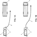
- a desired feature of ACC is that the resumption to the specified speed starts quickly when the driver starts to pull out. However, there can be a delay before the radar can determine that the road ahead is clear and, therefore, initiation of the vehicle acceleration may be delayed.
- a typical pathway P for a vehicle operating in this mode is illustrated in Figure 1A .
- indicator information to initiate an acceleration surge (also referred to as indicator surge) when the driver indicates to pull out.
- an acceleration surge also referred to as indicator surge
- the vehicle automatically accelerates. If the driver does not subsequently pull out, the vehicle will slow again and return to its normal follow distance after a few seconds. If the driver proceeds with the manoeuvre, any delay in returning to the set cruise speed is minimised as the vehicle is already accelerating.
- a typical pathway P for a vehicle operating in this mode is illustrated in Figure 1B .
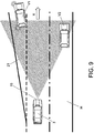
- acceleration surge function when indicating to take an exit ramp from a highway (to the left in regions such as the UK having left-hand traffic), the same acceleration surge function will be triggered, as illustrated by the vehicle pathway P in Figure 2 .
- the resulting increase in the vehicle speed can prove disconcerting in these circumstances.
- the acceleration surge function could be keyed to the hand of traffic of the vehicle (i.e. right-hand traffic, or left-hand traffic) based on its home market.
- any such keyed response would become incorrect if the vehicle is taken out of market (e.g. if a UK car is driven on the continent).
- DE10114187A1 discloses a method which involves taking into account vehicles in the overtaking lane and regulating the vehicle to an increased overtaking speed if overtaking.
- EP1520745A2 discloses a device for automatically recognizing and adjusting traffic direction.
- GB2317256A discloses a method and device for automatically detecting whether right-hand or left-hand traffic prevails in a traffic situation.
- WO2004/045895A1 discloses a system for evaluating the driving environment of a motor vehicle and for influencing the speed of said vehicle in its own lane.
- the present invention sets out to address at least some of the shortcomings associated with prior art systems.
- the present invention provides a method of operating an Adaptive Cruise Control of a subject vehicle, travelling in a first direction and having a first side and a second side, wherein an acceleration surge function is operable when an indicator is actuated by a driver to signal a driving manoeuvre to said first side or said second side, the method comprising:
- the acceleration surge function can be inhibited when the driver indicates a manoeuvre to the left side of the subject vehicle when driving in left-hand traffic; or to the right side of the subject vehicle when driving in right-hand traffic.
- the ACC can tailor vehicle operations, for example to allow correct reaction to an indicator signal by the driver. This can enable a surge of acceleration when pulling out under ACC control, which gives an impression of more responsive control to the driver.
- the method can comprise outputting an engine speed increase instruction in response to receipt of the indicator signal.
- the instruction can, for example, be output to an engine control module to increase the engine speed.
- the method can determine whether the acceleration surge is appropriate for the signalled manoeuvre. If the subject vehicle is operating in left-hand traffic, an acceleration surge is appropriate when indicating right, but not if indicating left (such as on an exit ramp). By identifying the hand of traffic, the appropriate action can be initiated even when the car is taken out of its home market. The method can be swapped or inhibited as desired.
- the hand of traffic may be identified by a user input, for example by operating a control on the dashboard.
- the hand of the traffic may be identified automatically, or by any other suitable method.
- Identifying the hand of traffic comprises:
- the method also comprises repeating steps (a) and (b) for a plurality of first object vehicles; and the hand of traffic identified in step (c) is based on threshold values for a predetermined number of object vehicles travelling in the same direction as the subject vehicle (3) and/or a predetermined number of object vehicles travelling in the opposite direction to the subject vehicle (3).
- the hand of traffic identified in step (c) can be based on statistical analysis performed on a pre-set minimum number of object vehicles travelling in the same direction as the subject vehicle and/or object vehicles travelling in the opposite direction to the subject vehicle. Only when a sufficient data set has been established of object vehicles travelling in the same direction and/or in the opposite direction, is the hand of traffic determined.
- the method can be used to determine whether the hand of traffic is to the right (i.e. right-hand traffic where vehicles drive on the right-hand side of the road), or to the left (i.e. left-hand traffic where vehicles drive on the left-hand side of the road).
- the method can track oncoming vehicles (i.e. vehicles travelling in the opposite direction to the subject vehicle) and/or same direction vehicles (i.e. vehicles travelling in the same direction as the subject vehicle).
- the first stationary target may, for example, be a parked vehicle, street furniture, or a barrier.
- the method can comprise operating a tracking device on the subject vehicle to track each first object vehicle and/or each first stationary target.
- the tracking device can comprise a radar, optical or infra-red tracking system.
- the tracking device can measure the speed of each first object vehicle and this can be combined with a measured speed of the subject vehicle to determine whether each first object vehicle is travelling in the same direction or in the opposite direction to the subject vehicle.
- the method at step (c) can comprise comparing the direction of travel of each first object vehicle to the first direction of travel of the subject vehicle.
- the hand of traffic can be identified as corresponding to the first side of the subject vehicle when each first object vehicle on the first side is travelling in the same direction as the subject vehicle. Conversely, the hand of traffic can be identified as corresponding to the second side of the subject vehicle if each first object vehicle on the first side of the subject vehicle is travelling in the opposite direction to the subject vehicle.
- the method can also compare the speed of each first object vehicle in relation to that of the subject vehicle. Where each first object vehicle is travelling in the same direction as the subject vehicle, tracking faster vehicles on the right side and/or slower vehicles on the left side of the subject vehicle can indicate a drive on left situation (i.e. left-hand traffic). Conversely, tracking slower vehicles on the right side and/or faster vehicles on the left side of the subject vehicle can indicate a drive on right scenario (i.e. right-hand traffic).
- the tracking of each first object vehicle in step (a) can comprise one or more of the following: (i) measuring the speed of each first object vehicle; (ii) measuring the distance to each first object vehicle; (iii) identifying the position of each first object vehicle in relation to the subject vehicle; and (iv) the direction of travel of each first object vehicle.
- the tracking of each first object vehicle in step (a) can comprise measuring the speed of each first object vehicle.
- the method whereby the direction of travel of each vehicle is determined in step (b) comprises comparing the measured speed of each first object vehicle with an actual speed of the subject vehicle.
- the method can comprise operating a processor to perform step (b) and/or step (c).
- the steps (a) and (b) of the method can be repeated for at least a second object vehicle tracked on the second side of the subject vehicle; and/or at least a second stationary target detected on the second side of the subject vehicle.
- the method can look at oncoming vehicles and same direction vehicles.
- the second stationary target may, for example, be a parked vehicle, street furniture, or a barrier.
- the tracking of the first and second object vehicles can be performed by the same tracking system, or by different tracking systems.
- tracking the first and second stationary targets can be performed by the same tracking system, or by different tracking systems.
- the step of tracking each second object vehicle can comprise measuring the speed of each second object vehicle.
- the direction of travel of each second object vehicle can be determined by comparing the measured speed of each second object vehicle with an actual speed of the subject vehicle
- the hand of traffic identified in step (c) can be based on monitoring a plurality of first object vehicles travelling in the same direction as the subject vehicle and a plurality of second object vehicles travelling in the opposite direction to the subject vehicle. Equally, the hand of traffic can be identified in step (c) by comparing the relative speed of vehicles travelling in the same direction on the first and second sides of the subject vehicle.
- the method can also be used to determine (when indicating out) if the acceleration surge should be inhibited, either because this will result in following an outside lane vehicle closely, or if the car is already in the outside lane and therefore cannot pull out.
- the acceleration surge function can be inhibited when it is determined that the distance between the subject vehicle and a first object vehicle or a second object vehicle on the side of the vehicle corresponding to the signalled driving manoeuvre is less than a predefined threshold.
- the present application relates to a method of operating an ACC of a subject vehicle to prevent undertaking, the method comprising identifying the hand of traffic in accordance with the method described herein, wherein a speed of the subject vehicle is reduced if it is determined that the subject vehicle will undertake each first object vehicle or each second object vehicle based on the identified hand of traffic.
- the method could comprise applying the brakes to avoid undertaking, but this would be unexpected by following drivers. Instead, the method can comprise the step of reducing engine drive, or inhibiting acceleration.
- the ACC can output an engine control signal for controlling the speed of the subject vehicle.
- An engine speed reduction signal can be output to reduce the engine speed and, accordingly, the speed of the subject vehicle.
- an engine speed increase signal can be output to increase the engine speed and, accordingly, the speed of the subject vehicle.
- a vehicle in an empty left lane may undertake a queue of cars in the middle lane (for left-hand traffic).
- the method according to the present invention could prevent this operation.
- the method described herein can further comprise the step of: (d) comparing the speed of each first object vehicle and each second object vehicle to identify the presence or absence of undertaking.
- An undertaking prevention function can be inhibited if it is determined that undertaking is permitted.
- the present invention relates to one or more computer-readable media having computer-readable instructions thereon which, when executed by a computer, cause the computer to perform all the steps of the method described herein.
- the method described herein can be machine-implemented.
- the present invention relates to a computer system comprising: programmable circuitry; and software encoded on at least one computer-readable medium to program the programmable circuitry to implement the method described herein.
- the present invention relates to an ACC module for a subject vehicle, the module comprising a processor for initiating an acceleration surge function when an indicator is operated by a driver to signal a driving manoeuvre to a first side or a second side of the subject vehicle, the processor being configured to:
- the module comprises a tracking device for tracking at least a first object vehicle on a first side of the subject vehicle and/or the presence of at least a first stationary target on said first side of the subject vehicle; the processor being configure to determine a direction of travel of each first object vehicle in relation to the subject vehicle, and to identify the hand of traffic based on the direction of travel of each first object vehicle and/or the presence of each first stationary target detected.
- the acceleration surge function can comprise outputting an engine speed increase instruction for increasing the engine speed.
- the instruction can, for example, be output to an engine control module to increase the engine speed.
- the processor can be configured to request a reduction in the speed of the subject vehicle if it determines that the subject vehicle will undertake each first object vehicle or each second object vehicle based on the identified hand of traffic.
- the tracking device can also be suitable for tracking at least a second object vehicle on a second side of the subject vehicle; and/or detecting the presence or absence of at least a second stationary target on the second side of the subject vehicle.
- the processor can be configured to compare the speed of each first object vehicle and each second object vehicle to identify the presence or absence of undertaking.
- the invention also relates to a vehicle incorporating an ACC module as described herein.
- the method(s) described herein can be implemented on a computational device comprising one or more processors, such as an electronic microprocessor.
- the processor(s) can be configured to perform computational instructions stored in memory or in a storage device.
- the controllers and/or control units described herein can comprise one or more processors configured to perform computational instructions.
- the present invention also relates to a computer program for controlling a processor, the computer program being executable to cause the processor to operate in accordance with the method(s) described herein.
- References herein to the left and right hand sides of the vehicle are to the respective sides of the vehicle when viewed from the rear of the vehicle looking towards the front of the vehicle.
- the first and second sides of the vehicle can refer to the left and right hand sides respectively; or conversely the right and left hand sides respectively.
- a hand of traffic control unit 1 for determining a prevailing hand of traffic (i.e. left-hand traffic, or right-hand traffic) for a subject vehicle 3 in accordance with the present invention will now be described.
- the subject vehicle 3 is illustrated as driving in left-hand traffic on a highway H in a first direction X.
- the expected pathway of the subject vehicle 3 is indicated by a dashed line P.
- a hand of traffic is specified in a car configuration data file (initially set by the vehicle manufacturer or supplier) for the intended home market of the vehicle 3.
- the hand of traffic may change if the vehicle 3 is taken to a different country and this may adversely affect vehicle systems.
- the control unit 1 can identify the local hand of traffic based on analysis of vehicle movements in relation to the subject vehicle 3. By determining the hand of traffic, the control unit 1 can provide an appropriate system response to a driver action, such as an indicator manoeuvre signal.
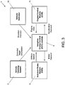
- the control unit 1 comprises an Adaptive Cruise Control (ACC) module 5 for maintaining the subject vehicle 3 at a cruise speed specified by the driver.
- the ACC module 5 comprises a microprocessor (not shown) configured to receive data relating to the operating parameters of the subject vehicle 3.
- the ACC module 5 is connected to a vehicle tracking system 7, an anti-lock brake system (ABS) 9, an engine control module (ECM) 11, and a driver operated vehicle indicator 13.
- ABS anti-lock brake system
- ECM engine control module
- the vehicle tracking system 7 can track an object vehicle (denoted by the reference V) and output tracked vehicle data to the ACC module 5, including the relative speed and direction of travel of the object vehicle V.
- the ACC module 5 receives real-time data on the absolute speed of the subject vehicle 3 from the ABS 9 and, optionally, can output braking instructions to the ABS 9, for example to initiate braking of the vehicle 3.
- the ACC module 5 receives engine speed data from the ECM 11 and can output acceleration/deceleration instructions to the ECM 11 to increase/decrease the engine speed.
- the vehicle indicator 13 is operated by the driver of the vehicle 3 to signal an intended driving manoeuvre to the left hand side or right hand side of the vehicle 3.
- the absolute speed of the object vehicle V is calculated by summing the speed of the subject vehicle 3 and the measured relative speed of the object vehicle V.
- the vehicle tracking system 7 can thereby determine whether the object vehicle V is travelling in the same direction as the subject vehicle 3 or in the opposite direction (i.e. is oncoming traffic).
- the vehicle tracking system 7 also tracks the position of the object vehicle V in relation to the subject vehicle 3 to determine if it is on the left or right hand side.
- the ACC module 5 has a Follow Mode for automatically adjusting the speed of the subject vehicle 3 in response to changes in the speed of a lead object vehicle V.
- the vehicle tracking system 7 comprises a first forward-facing radar tracking system 15 for tracking object vehicles V and stationary targets T.
- the first radar tracking system 15 is provided behind the grill of the subject vehicle 3 and can track the position and speed of object vehicles V in front of and to the left and right of the subject vehicle 3. If a slower object vehicle V is detected in front of the subject vehicle 3, the ACC module 5 will output deceleration instructions to the ECM 11 to decrease the engine speed thereby reducing the speed of the subject vehicle 3 to match that of the object vehicle V.
- a blind-spot detector 17 is provided for detecting the presence of object vehicles V in a driver's blind spot.
- the subject vehicle 3 has indicators on the right- and left-hand sides for signalling driving manoeuvres in the respective directions.
- the driver controls the indicators in conventional manner using the vehicle indicator 13 which comprises an indicator switch (not shown) mounted on the steering column.
- the left and right indicators are illustrated in the accompanying Figures as being engaged by outwardly radiating lines referenced as "I".
- the ACC module 5 is configured to initiate an acceleration surge when the indicators are engaged to reduce the time elapsed before the vehicle 3 returns to a specified cruise speed when it pulls out to overtake a vehicle, as illustrated in Figure 1B .
- an acceleration surge might be disconcerting for the driver.
- the ACC module 5 according to the present invention can selectively inhibit the acceleration surge function.
- the ACC module 5 is configured to inhibit the acceleration surge function when the indicators are engaged to signal a manoeuvre to the side of the subject vehicle 3 corresponding to the identified hand of traffic. If the ACC module 5 determines that the vehicle 3 is operating in a left-hand traffic region, the acceleration surge function would be inhibited when the driver operates the indicators to signal a manoeuvre to the left. Conversely, if the ACC module 5 determines that the vehicle 3 is operating in a right-hand traffic region, the acceleration surge function would be inhibited when the driver operates the indicators to signal a manoeuvre to the right.
- the ACC module 5 analyses the local traffic conditions to determine the prevailing hand of traffic in order to control operation of the acceleration surge function.
- the hand of traffic can be determined by considering the position of the object vehicle V in relation to the subject vehicle 3, the direction of travel of the object vehicle V (same direction or opposite direction) and the relative speed of the object vehicle V.
- oncoming traffic if a plurality of object vehicles V is detected travelling in the opposite direction on the right-hand side of the subject vehicle 3, this indicates left-hand traffic. Conversely, if a plurality of object vehicles V is detected travelling in the opposite direction on the left-hand side of the subject vehicle 3, this indicates right-hand traffic.
- Using a count of the object vehicles V with a suitable minimum threshold provides robustness against unusual situations, such as service roads or road works. Tracking oncoming vehicles is appropriate for single carriageway roads where large numbers of oncoming vehicles are encountered.
- an object vehicle V moving faster or slower than the subject vehicle 3 can be classified as left or right lane based on whether they are on the respective left or right-hand sides of the subject vehicle 3. Tracking faster object vehicles V on the right side and/or slower object vehicles V on the left side of the subject vehicle 3 indicates left-hand traffic. Conversely, tracking slower object vehicles V on the right side and/or faster object vehicles V on the left side of the subject vehicle indicate right-hand traffic. Again, a minimum threshold of object vehicles V is tracked to provide robustness. Tracking same direction vehicles can be employed in situations where vehicles travelling in the opposite direction may be obscured by a central reservation.
- the applicable judgement counters to determine the hand of traffic are summarised in Table A provided in Figure 4 .
- the relative speed of the subject vehicle 3 is summarised as being faster or slower than the object vehicle V; and the relative position of the object vehicle V is summarised as being on the left or right-hand side of the subject vehicle 3. If the absolute speed of the object vehicle V is positive, the ACC module 5 determines that the subject vehicle 3 and the object vehicle V are travelling in the same direction. Conversely, if the absolute speed of the object vehicle V is negative, the ACC module 5 determines that the subject vehicle 3 and the object vehicle V are travelling in opposite directions. The ACC module 5 performs separate analysis in respect of object vehicles V travelling in the same direction as the subject vehicle 3 and object vehicles V travelling in the opposite direction.
- a first analysis is performed for object vehicles V travelling in the same direction as the subject vehicle 3; and a second analysis is performed for object vehicles V travelling in the opposite direction to the subject vehicle 3.
- a first decision is output following the first analysis of a threshold number of object vehicles V travelling in the same direction as the subject vehicle 3.
- a second decision is output following the second analysis of a threshold number of object vehicles V travelling in the opposite direction to the subject vehicle 3.
- the minimum threshold for analysis of the object vehicles V travelling in each direction is typically twenty (20) vehicles.
- the operation of the control unit 1 is based on said first and second decisions, as follows: If neither the first decision nor the second decision is available, a fallback decision can be based on the car configuration data or the last detected hand of traffic. The acceleration surge can optionally be inhibited in the absence of a conclusive detected hand of traffic.
- the decision will be employed provided it matches the car configuration data. Otherwise, the acceleration surge will be inhibited.
- the acceleration surge will be enabled provided the first and second decisions both match the car configuration data. Otherwise, the acceleration surge will be inhibited.
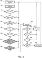
- a test is performed to determine when the indicators are operated by the driver (STEP 100) and the process is initiated when a left or right indicator is detected (STEP 110).
- the process reverts to the original test routine (STEP 100).
- the initial conditions consist of checking that the vehicle speed is greater than 50mph (STEP 120); that the Follow Mode of the ACC module 5 is engaged (STEP 130); that the speed set in the cruise control is greater than the actual vehicle speed (STEP 140); that the range to the object vehicle V is within a specified range for example less than 70 metres and greater than 16 metres (STEP 150); and that the inverse of the calculated time to collision (TTC) is less than 0.11 (STEP 160).
- a further check is performed to confirm that hand of traffic determined by the first and second decisions match the hand of traffic specified in the car configuration data (STEP 170).
- a further test is then performed by the first radar tracking system 5 to check that the adjacent lane (in the direction of the signalled manoeuvre) is clear (STEP 180). If the adjacent lane is clear, the acceleration surge is initiated (STEP 190).
- a series of cancellation conditions are monitored whilst the acceleration surge is maintained. If any of the cancellation conditions are met, a fast ramp-off from the acceleration surge is initiated (STEP 200). Specifically, the distance to the object vehicle V is measured and if the range falls below 15 metres the acceleration surge is cancelled (STEP 210). If the inverse of the calculated time to collision (TTC) rises above 0.11, the acceleration surge is cancelled (STEP 220). Also, the acceleration surge is terminated after 5.5 seconds (STEP 230).
- the acceleration surge is terminated (STEP 240).
- a slow ramp-off (STEP 250) is engaged in this scenario to provide a more gradual transition.
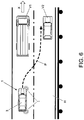
- the first radar tracking system 5 checks that the adjacent lane in the direction of the signalled manoeuvre is clear before initiating the acceleration surge (STEP 180). If, for example, the indicators are operated to signal an overtaking manoeuvre of a first object vehicle V1, the control unit 1 will check that the adjacent lane to the side of the subject vehicle 3 corresponding to the direction of the signalled drive manoeuvre is clear. As illustrated in Figure 6 , if the first radar tracking system 5 determines that a second object vehicle V2 is occupying the adjacent lane corresponding to the direction of the signalled drive manoeuvre, the acceleration surge is inhibited.
- the vehicle tracking system 7 can track one or more stationary targets T, such as a central reservation or barrier alongside a highway. As illustrated in Figure 7 , the first radar tracking system 15 detects at least one stationary target T on a right-hand side of the subject vehicle 3. The ACC module 5 determines that the stationary target(s) T indicate that the vehicle 3 is already in the outside (right-hand) lane and, therefore, inhibits the acceleration surge function when the driver indicates a right-hand manoeuvre, for example to overtake a first object vehicle V1. The acceleration surge function would also be inhibited if the distance to a second object (lead) vehicle V2 in front of the subject vehicle 3 is below a threshold limit.
- the blind-spot detector 17 monitors a blind-spot region 19 to the rear of the vehicle 3 on the driver's side.
- the driver indicates a right-hand manoeuvre to overtake a first object vehicle V1 in front of the subject vehicle 3.
- the blind-spot detector 17 senses a second object vehicle V2 in the blind-spot region 19 on the right-hand side of the subject vehicle 3. Accordingly, the acceleration surge is inhibited whilst the object vehicle V is in the blind-spot region 19.
- An alert can be provided to notify the driver that an object vehicle V is in the blind-spot region 19. It will be appreciated that the blind-spot detector 17 could monitor a blind-spot region on the left-hand side of the vehicle 3.
- the ACC module 5 can also operate to prevent undertaking within a radar scanning zone 21.
- the ACC will resume the set cruise speed if a first object vehicle V1 ahead of the subject vehicle 3 moves out of the way, for example to leave a highway.
- the resulting increase in speed of the subject vehicle 3 by the ACC could result in an undertaking manoeuvre of a second object vehicle V2.
- the ACC module 5 according to the present invention can identify the hand of traffic and recognise an undertaking scenario. It is envisaged that the ACC module 5 would prevent undertaking if the first and second decisions both indicated the same hand of traffic. Otherwise, it is envisaged that the ACC module 5 would not prevent undertaking.
- the subject vehicle 3 could comprise a second radar tracking system, for example to track object vehicles V behind or on each side the subject vehicle 3.
- First and second tracking systems could be provided for tracking object vehicles V on the left and right hand sides respectively of the subject vehicle 3.
- alternate tracking systems such as optical or infra-red, could be employed.
- the hand of traffic information derived by the ACC module 5 has been described as having particular applications in relation to the operation of the ACC.
- the traffic information may be applied to other systems, for example headlight alignment, dipping and/or beam pattern.
Claims (12)
- Procédé de fonctionnement d'un régulateur de vitesse adaptatif (5) d'un véhicule sujet (3), se déplaçant dans une première direction et ayant un premier côté et un second côté, dans lequel une fonction d'accélération brusque est opérationnelle lorsqu'un indicateur est actionné par un conducteur pour signaler une manœuvre de conduite audit premier côté ou audit second côté, le procédé comprenant :l'identification de la main de la circulation ; etl'inhibition de la fonction de montée en charge en accélération lorsque la manœuvre de conduite parallèle à la manœuvre de conduite prévue est du même côté du véhicule en cause (3) que la main de la circulation".le procédé étant caractérisé en ce que l'identification de la main de traffic comprend:et/ou la présence ou l'absence de chaque première cible stationnaire ;(a) suivre au moins un premier véhicule objet sur ledit premier côté du sujet et/ou détecter la présence ou l'absence d'au moins une première cible stationnaire sur ledit premier côté du véhicule sujet (3) ;b) déterminer le sens de marche de chaque véhicule du premier objet par rapport au véhicule en question (3) ; etc) l'identification de la main de la circulation en fonction du sens de circulation de chaque premier conducteur
dans laquelle les étapes (a) et (b) sont répétées pour une pluralité de premiers véhicules objets ; et la main de identifié à l'étape (c) est basé sur des valeurs seuils pour un nombre prédéterminé de véhicules objets circulant dans la même direction que le véhicule sujet (3) et/ou un nombre prédéterminé de véhicules objets circulant dans la direction opposée au véhicule sujet (3). - Procédé selon la revendication 1, dans lequel l'étape (c) comprend la comparaison de l'activité la direction de déplacement de chaque premier véhicule objet vers ladite première direction de déplacement ; la main de circulation étant identifiée comme correspondant audit premier côté lorsque chaque premier véhicule objet du premier côté se déplace dans la même direction que le véhicule sujet (3).
- Procédé selon la revendication 1 ou 2, dans lequel l'étape (c) comprend les étapes suivantes comparer la direction de déplacement de chaque premier véhicule objet à ladite première direction de déplacement ; la main de la circulation étant identifiée comme correspondant au deuxième côté si chaque premier véhicule objet du premier côté se déplace dans la direction opposée au véhicule sujet (3).
- Procédé tel que revendiqué dans l'une quelconque des revendications 1 à 3, dans lequel les étapes (a) et (b) sont les suivantes répétée pour au moins un deuxième véhicule objet suivi sur le deuxième côté du véhicule sujet (3) ; et/ou au moins une deuxième cible fixe détectée sur le deuxième côté du véhicule sujet (3).
- Procédé selon la revendication 4, dans lequel la main de circulation identifiée à l'étape (c) est basé sur la surveillance d'une pluralité de véhicules du premier objet se déplaçant dans la même direction que le véhicule sujet (3) et d'une pluralité de véhicules du second objet se déplaçant dans la direction oppose vers le véhicule en question (3).
- Procédé de fonctionnement d'un régulateur de vitesse adaptatif (5) d'un véhicule sujet (3) pour empêcher une entreprise, le procédé comprenant l'identification de la main du trafic selon l'une quelconque des revendications 1 à 5, dans lequel une vitesse du véhicule sujet (3) est réduite si elle est a déterminé que le véhicule en question (3) entreprendra un premier véhicule objet ou un deuxième véhicule objet en fonction de la main de circulation identifiée.
- Procédé de fonctionnement d'un régulateur de vitesse adaptatif (5) d'un véhicule sujet (3), le procédé comprenant l'identification de la main du trafic conformément à la revendication 6, le proceed comprenant en outre l'étape de : d) comparer la vitesse de chaque véhicule du premier objet et de chaque véhicule du second objet pour déterminer la présence ou l'absence d'engagement.
- Un ou plusieurs supports lisibles par ordinateur comportant des instructions lisibles par ordinateur qui, lorsqu'elles sont exécutées par un ordinateur, obligent l'ordinateur à effectuer toutes les étapes suivantes la méthode selon l'une quelconque des revendications précédentes.
- Module de régulateur de vitesse adaptatif (5) pour un véhicule sujet, le module comprenant un processeur pour déclencher une fonction d'accélération brusque lorsqu'un indicateur (13) est actionné par un conducteur pour signaler une manœuvre de conduite à un premier côté ou à un second côté de l'élément véhicule sujet, le processeur étant configuré pour :identifier la main de la circulation ; etinhiber la fonction d'accélération brusque lorsque le processeur détermine que la manœuvre de conduite signalée est du même côté que la main identifiée de la circulation,le module comprenant en outre un dispositif de suivi,caractérisé en ce que l'identification de la main de circulation comprend :(a) suivre au moins un premier véhicule objet sur ledit premier côté du véhicule sujet, et/ou détecter la présence ou l'absence d'au moins une première cible fixe sur ledit premier côté du véhicule sujet (3) ;(b) déterminer le sens de déplacement de chaque véhicule du premier objet par rapport au véhicule visé (3) ; et(c) l'identification de la main de la circulation en fonction du sens de déplacement de chaque véhicule du premier objet, et/ou de la présence ou de l'absence de chaque première cible stationnaire ;dans laquelle les étapes (a) et (b) sont répétées pour une pluralité de premiers véhicules objets ; et la main de circulation identifiée à l'étape (c) est basée sur des valeurs seuils pour un nombre prédéterminé de véhicules objets circulant dans la même direction que le véhicule sujet (3) et/ou un nombre prédéterminé de véhicules objets circulant dans la direction opposée au sujet
véhicule (3). - Module de régulateur de vitesse adaptatif (5) selon la revendication 9, dans lequel le processeur est configuré pour demander une réduction de la vitesse du véhicule sujet (3) s'il détermine que le véhicule sujet (3) va entreprendre chaque premier véhicule objet ou chaque seconde véhicule objet en fonction de la main identifiée de la circulation.
- Module de régulateur de vitesse adaptatif selon la revendication 9 ou 10, dans lequel le dispositif de repérage est également approprié pour repérer au moins un deuxième véhicule objet sur un deuxième côté du véhicule en question (3) ; et/ou détecter la présence ou l'absence d'au moins un deuxième cible fixe du deuxième côté du véhicule en question (3).
- Véhicule ayant un module de régulateur de vitesse adaptatif tel que réclamé dans l'une quelconque des revendications 9 à 11 ou adapté pour exécuter la méthode de l'une quelconque des revendications 1-8.
Applications Claiming Priority (2)
| Application Number | Priority Date | Filing Date | Title |
|---|---|---|---|
| GB1200282.0A GB2498223B (en) | 2012-01-09 | 2012-01-09 | Method and control unit for monitoring traffic |
| PCT/EP2013/050213 WO2013104618A2 (fr) | 2012-01-09 | 2013-01-08 | Procédé et unité de commande pour contrôler un trafic |
Publications (2)
| Publication Number | Publication Date |
|---|---|
| EP2802496A2 EP2802496A2 (fr) | 2014-11-19 |
| EP2802496B1 true EP2802496B1 (fr) | 2020-01-01 |
Family
ID=45788653
Family Applications (1)
| Application Number | Title | Priority Date | Filing Date |
|---|---|---|---|
| EP13701714.1A Active EP2802496B1 (fr) | 2012-01-09 | 2013-01-08 | Procédé et unité de commande pour contrôler un trafic |
Country Status (7)
| Country | Link |
|---|---|
| US (1) | US9555804B2 (fr) |
| EP (1) | EP2802496B1 (fr) |
| JP (2) | JP2015505285A (fr) |
| KR (2) | KR20140107629A (fr) |
| CN (2) | CN104039623B (fr) |
| GB (2) | GB2498223B (fr) |
| WO (1) | WO2013104618A2 (fr) |
Families Citing this family (14)
| Publication number | Priority date | Publication date | Assignee | Title |
|---|---|---|---|---|
| GB2498223B (en) * | 2012-01-09 | 2015-08-26 | Jaguar Land Rover Ltd | Method and control unit for monitoring traffic |
| US9180882B1 (en) * | 2012-06-20 | 2015-11-10 | Google Inc. | Avoiding blind spots of other vehicles |
| CN103496368B (zh) * | 2013-09-25 | 2016-04-20 | 吉林大学 | 具有学习能力的汽车协同式自适应巡航控制系统及方法 |
| EP3736732A1 (fr) * | 2014-01-30 | 2020-11-11 | Mobileye Vision Technologies Ltd. | Systèmes et procédés de reconnaissance de fin de voie |
| DE112015001152A5 (de) * | 2014-05-22 | 2016-12-22 | Conti Temic Microelectronic Gmbh | Verfahren und Vorrichtung zur Erhöhung der Sicherheit bei einem Überholvorgang eines Fahrzeuges |
| JP2016070772A (ja) * | 2014-09-30 | 2016-05-09 | 富士通テン株式会社 | レーダ装置、車両制御システム、および、信号処理方法 |
| JP6086107B2 (ja) * | 2014-10-17 | 2017-03-01 | トヨタ自動車株式会社 | 車両用制駆動力制御装置 |
| EP3208739A1 (fr) * | 2016-02-22 | 2017-08-23 | Autoliv Development AB | Système d'assistance au conducteur et procédé pour véhicule à moteur |
| US10493984B2 (en) * | 2016-06-27 | 2019-12-03 | Nissan Motor Co., Ltd. | Vehicle control method and vehicle control device |
| CN108428366B (zh) * | 2017-02-15 | 2022-03-18 | 中兴通讯股份有限公司 | 一种辅助驾驶方法及装置 |
| JP7273359B2 (ja) * | 2019-01-29 | 2023-05-15 | トヨタ自動車株式会社 | 車両の運転支援装置 |
| CN111627247B (zh) * | 2019-02-28 | 2022-02-18 | 上海汽车集团股份有限公司 | 一种多车编队控制方法及装置 |
| CN110920614B (zh) * | 2019-10-30 | 2021-11-23 | 苏州智加科技有限公司 | 变道控制方法、装置、设备及存储介质 |
| FR3127188B1 (fr) * | 2021-09-22 | 2023-10-27 | Psa Automobiles Sa | Détection d’une intention de changement de voie pour améliorer le contrôle de la vitesse d’un véhicule |
Citations (1)
| Publication number | Priority date | Publication date | Assignee | Title |
|---|---|---|---|---|
| EP2353957A2 (fr) * | 2010-01-14 | 2011-08-10 | Ford Global Technologies, LLC | Procédé et dispositif destinés à assister un conducteur lors d'une action de dépassement |
Family Cites Families (17)
| Publication number | Priority date | Publication date | Assignee | Title |
|---|---|---|---|---|
| JPS60261736A (ja) * | 1984-06-11 | 1985-12-25 | Nissan Motor Co Ltd | 車両走行制御装置 |
| DE4200694B4 (de) | 1992-01-14 | 2004-04-29 | Robert Bosch Gmbh | Verfahren zur Geschwindigkeits- und Abstandsregelung eines Fahrzeugs |
| DE19637053C2 (de) * | 1996-09-12 | 2000-03-09 | Bosch Gmbh Robert | Verfahren und Vorrichtung zur automatischen Erkennung von Rechts- oder Linksverkehr |
| DE19704854A1 (de) * | 1997-02-10 | 1998-08-13 | Itt Mfg Enterprises Inc | Verfahren und Vorrichtung zur Regelung der Längsdynamik eines Fahrzeugs |
| DE19859284A1 (de) * | 1998-12-22 | 2000-06-29 | Bosch Gmbh Robert | Verfahren und Vorrichtung zur Geschwindigkeits- und Abstandsregelung eines Kraftfahrzeuges |
| DE10007501A1 (de) * | 2000-02-18 | 2001-09-13 | Daimler Chrysler Ag | Verfahren und Vorrichtung zur Erfassung und Überwachung einer Mehrzahl von vorausfahrenden Fahrzeugen |
| DE10114187A1 (de) * | 2001-03-23 | 2002-09-26 | Bosch Gmbh Robert | Verfahren und Vorrichtung zur Unterstützung eines Überholvorgangs bei Kraftfahrzeugen |
| DE10254423A1 (de) * | 2002-11-21 | 2004-06-03 | Lucas Automotive Gmbh | System zur Beeinflussung der Geschwindigkeit eines Kraftfahrzeuges |
| DE10254402B4 (de) * | 2002-11-21 | 2011-02-17 | Lucas Automotive Gmbh | System zur Beeinflussung der Geschwindigkeit eines Kraftfahrzeuges |
| DE10345809A1 (de) * | 2003-09-30 | 2005-04-21 | Bosch Gmbh Robert | Verfahren und Vorrichtung zur Erkennung und Einstellung des Verkehrssinns |
| US7482916B2 (en) * | 2004-03-15 | 2009-01-27 | Anita Au | Automatic signaling systems for vehicles |
| DE102006027326A1 (de) * | 2006-06-13 | 2007-12-20 | Robert Bosch Gmbh | Spurwechselassistent für Kraftfahrzeuge |
| JP2008068751A (ja) | 2006-09-14 | 2008-03-27 | Mazda Motor Corp | 車両の走行制御装置 |
| DE102007059083A1 (de) * | 2006-12-19 | 2008-06-26 | Adc Automotive Distance Control Systems Gmbh | Vorrichtung zur reversiblen Einstellung von Kraftfahrzeugsteuersystemen |
| JP4933962B2 (ja) * | 2007-06-22 | 2012-05-16 | 富士重工業株式会社 | 分岐路進入判定装置 |
| JP5304735B2 (ja) * | 2010-06-15 | 2013-10-02 | 三菱自動車工業株式会社 | 追従制御装置 |
| GB2498223B (en) * | 2012-01-09 | 2015-08-26 | Jaguar Land Rover Ltd | Method and control unit for monitoring traffic |
-
2012
- 2012-01-09 GB GB1200282.0A patent/GB2498223B/en active Active
-
2013
- 2013-01-08 WO PCT/EP2013/050213 patent/WO2013104618A2/fr active Application Filing
- 2013-01-08 JP JP2014550719A patent/JP2015505285A/ja active Pending
- 2013-01-08 US US14/371,098 patent/US9555804B2/en active Active
- 2013-01-08 CN CN201380005048.5A patent/CN104039623B/zh not_active Expired - Fee Related
- 2013-01-08 KR KR1020147020970A patent/KR20140107629A/ko active Search and Examination
- 2013-01-08 GB GB1300283.7A patent/GB2499501A/en not_active Withdrawn
- 2013-01-08 EP EP13701714.1A patent/EP2802496B1/fr active Active
- 2013-01-08 CN CN201610576820.4A patent/CN106184212A/zh active Pending
- 2013-01-08 KR KR1020167013747A patent/KR20160066053A/ko not_active Application Discontinuation
-
2016
- 2016-08-18 JP JP2016160854A patent/JP6381592B2/ja active Active
Patent Citations (1)
| Publication number | Priority date | Publication date | Assignee | Title |
|---|---|---|---|---|
| EP2353957A2 (fr) * | 2010-01-14 | 2011-08-10 | Ford Global Technologies, LLC | Procédé et dispositif destinés à assister un conducteur lors d'une action de dépassement |
Also Published As
| Publication number | Publication date |
|---|---|
| GB2498223A (en) | 2013-07-10 |
| WO2013104618A2 (fr) | 2013-07-18 |
| US20150025770A1 (en) | 2015-01-22 |
| US9555804B2 (en) | 2017-01-31 |
| WO2013104618A3 (fr) | 2013-12-19 |
| GB201200282D0 (en) | 2012-02-22 |
| KR20140107629A (ko) | 2014-09-04 |
| EP2802496A2 (fr) | 2014-11-19 |
| GB2498223B (en) | 2015-08-26 |
| JP2016197464A (ja) | 2016-11-24 |
| GB201300283D0 (en) | 2013-02-20 |
| GB2499501A (en) | 2013-08-21 |
| KR20160066053A (ko) | 2016-06-09 |
| CN106184212A (zh) | 2016-12-07 |
| CN104039623A (zh) | 2014-09-10 |
| JP2015505285A (ja) | 2015-02-19 |
| CN104039623B (zh) | 2016-08-17 |
| JP6381592B2 (ja) | 2018-08-29 |
Similar Documents
| Publication | Publication Date | Title |
|---|---|---|
| EP2802496B1 (fr) | Procédé et unité de commande pour contrôler un trafic | |
| US11731614B2 (en) | Apparatus and method for controlling vehicle to avoid or mitigate collision | |
| CN109664882B (zh) | 一种避免道路车辆二次碰撞的方法、系统及电子设备 | |
| CN111016902B (zh) | 一种车辆换道时的车速辅助控制方法、系统及汽车 | |
| CN106985780B (zh) | 车辆安全辅助系统 | |
| US9008957B2 (en) | Method and device for avoiding and/or reducing the consequences of collisions | |
| US8005616B2 (en) | Method for determining relevant objects | |
| US7715275B2 (en) | Start assist system for motor vehicles | |
| CN110001647B (zh) | 车辆触发变道方法、系统及计算机可读存储介质 | |
| US11713041B2 (en) | Control system and control method for driving a motor vehicle | |
| JP5163991B2 (ja) | 複雑な交通状況における車両の速度制御方法 | |
| EP2913234B1 (fr) | Freinage automatique en marche arrière | |
| US11427167B2 (en) | Method for performing emergency braking in a motor vehicle and emergency braking system for performing the method | |
| CN111942352B (zh) | 考虑转向路径的自适应aeb系统及其控制方法 | |
| JP2012121534A (ja) | 車両の自動制動装置 | |
| EP2724177A1 (fr) | Systèmes d'aide au conducteur améliorés utilisant radar et vidéo | |
| KR20140057583A (ko) | 자동차용 안전 장치 | |
| CN112896157A (zh) | 一种防御性驾驶控制方法、装置、系统、车载终端及存储介质 | |
| US20220144269A1 (en) | Method for securing a vehicle | |
| CN114919574A (zh) | 基于前车运行状态的自动紧急避让系统及控制方法 | |
| EP4015326A1 (fr) | Système de commande de véhicule, véhicule et procédé | |
| CN115703463A (zh) | 用于控制车辆的装置和方法 |
Legal Events
| Date | Code | Title | Description |
|---|---|---|---|
| PUAI | Public reference made under article 153(3) epc to a published international application that has entered the european phase |
Free format text: ORIGINAL CODE: 0009012 |
|
| 17P | Request for examination filed |
Effective date: 20140811 |
|
| AK | Designated contracting states |
Kind code of ref document: A2 Designated state(s): AL AT BE BG CH CY CZ DE DK EE ES FI FR GB GR HR HU IE IS IT LI LT LU LV MC MK MT NL NO PL PT RO RS SE SI SK SM TR |
|
| DAX | Request for extension of the european patent (deleted) | ||
| STAA | Information on the status of an ep patent application or granted ep patent |
Free format text: STATUS: EXAMINATION IS IN PROGRESS |
|
| 17Q | First examination report despatched |
Effective date: 20180712 |
|
| GRAP | Despatch of communication of intention to grant a patent |
Free format text: ORIGINAL CODE: EPIDOSNIGR1 |
|
| STAA | Information on the status of an ep patent application or granted ep patent |
Free format text: STATUS: GRANT OF PATENT IS INTENDED |
|
| INTG | Intention to grant announced |
Effective date: 20190729 |
|
| GRAS | Grant fee paid |
Free format text: ORIGINAL CODE: EPIDOSNIGR3 |
|
| GRAA | (expected) grant |
Free format text: ORIGINAL CODE: 0009210 |
|
| STAA | Information on the status of an ep patent application or granted ep patent |
Free format text: STATUS: THE PATENT HAS BEEN GRANTED |
|
| RBV | Designated contracting states (corrected) |
Designated state(s): AL AT BE BG CH CY CZ DE DK EE ES FI FR GR HR HU IE IS IT LI LT LU LV MC MK MT NL NO PL PT RO RS SE SI SK SM TR |
|
| AK | Designated contracting states |
Kind code of ref document: B1 Designated state(s): AL AT BE BG CH CY CZ DE DK EE ES FI FR GR HR HU IE IS IT LI LT LU LV MC MK MT NL NO PL PT RO RS SE SI SK SM TR |
|
| REG | Reference to a national code |
Ref country code: CH Ref legal event code: EP Ref country code: AT Ref legal event code: REF Ref document number: 1219430 Country of ref document: AT Kind code of ref document: T Effective date: 20200115 |
|
| REG | Reference to a national code |
Ref country code: IE Ref legal event code: FG4D |
|
| REG | Reference to a national code |
Ref country code: DE Ref legal event code: R096 Ref document number: 602013064562 Country of ref document: DE |
|
| REG | Reference to a national code |
Ref country code: NL Ref legal event code: MP Effective date: 20200101 |
|
| REG | Reference to a national code |
Ref country code: LT Ref legal event code: MG4D |
|
| PG25 | Lapsed in a contracting state [announced via postgrant information from national office to epo] |
Ref country code: FI Free format text: LAPSE BECAUSE OF FAILURE TO SUBMIT A TRANSLATION OF THE DESCRIPTION OR TO PAY THE FEE WITHIN THE PRESCRIBED TIME-LIMIT Effective date: 20200101 Ref country code: NO Free format text: LAPSE BECAUSE OF FAILURE TO SUBMIT A TRANSLATION OF THE DESCRIPTION OR TO PAY THE FEE WITHIN THE PRESCRIBED TIME-LIMIT Effective date: 20200401 Ref country code: RS Free format text: LAPSE BECAUSE OF FAILURE TO SUBMIT A TRANSLATION OF THE DESCRIPTION OR TO PAY THE FEE WITHIN THE PRESCRIBED TIME-LIMIT Effective date: 20200101 Ref country code: LT Free format text: LAPSE BECAUSE OF FAILURE TO SUBMIT A TRANSLATION OF THE DESCRIPTION OR TO PAY THE FEE WITHIN THE PRESCRIBED TIME-LIMIT Effective date: 20200101 Ref country code: PT Free format text: LAPSE BECAUSE OF FAILURE TO SUBMIT A TRANSLATION OF THE DESCRIPTION OR TO PAY THE FEE WITHIN THE PRESCRIBED TIME-LIMIT Effective date: 20200527 Ref country code: NL Free format text: LAPSE BECAUSE OF FAILURE TO SUBMIT A TRANSLATION OF THE DESCRIPTION OR TO PAY THE FEE WITHIN THE PRESCRIBED TIME-LIMIT Effective date: 20200101 Ref country code: CZ Free format text: LAPSE BECAUSE OF FAILURE TO SUBMIT A TRANSLATION OF THE DESCRIPTION OR TO PAY THE FEE WITHIN THE PRESCRIBED TIME-LIMIT Effective date: 20200101 |
|
| PG25 | Lapsed in a contracting state [announced via postgrant information from national office to epo] |
Ref country code: BG Free format text: LAPSE BECAUSE OF FAILURE TO SUBMIT A TRANSLATION OF THE DESCRIPTION OR TO PAY THE FEE WITHIN THE PRESCRIBED TIME-LIMIT Effective date: 20200401 Ref country code: GR Free format text: LAPSE BECAUSE OF FAILURE TO SUBMIT A TRANSLATION OF THE DESCRIPTION OR TO PAY THE FEE WITHIN THE PRESCRIBED TIME-LIMIT Effective date: 20200402 Ref country code: LV Free format text: LAPSE BECAUSE OF FAILURE TO SUBMIT A TRANSLATION OF THE DESCRIPTION OR TO PAY THE FEE WITHIN THE PRESCRIBED TIME-LIMIT Effective date: 20200101 Ref country code: IS Free format text: LAPSE BECAUSE OF FAILURE TO SUBMIT A TRANSLATION OF THE DESCRIPTION OR TO PAY THE FEE WITHIN THE PRESCRIBED TIME-LIMIT Effective date: 20200501 Ref country code: SE Free format text: LAPSE BECAUSE OF FAILURE TO SUBMIT A TRANSLATION OF THE DESCRIPTION OR TO PAY THE FEE WITHIN THE PRESCRIBED TIME-LIMIT Effective date: 20200101 Ref country code: HR Free format text: LAPSE BECAUSE OF FAILURE TO SUBMIT A TRANSLATION OF THE DESCRIPTION OR TO PAY THE FEE WITHIN THE PRESCRIBED TIME-LIMIT Effective date: 20200101 |
|
| REG | Reference to a national code |
Ref country code: CH Ref legal event code: PL |
|
| REG | Reference to a national code |
Ref country code: DE Ref legal event code: R097 Ref document number: 602013064562 Country of ref document: DE |
|
| REG | Reference to a national code |
Ref country code: BE Ref legal event code: MM Effective date: 20200131 |
|
| PG25 | Lapsed in a contracting state [announced via postgrant information from national office to epo] |
Ref country code: LU Free format text: LAPSE BECAUSE OF NON-PAYMENT OF DUE FEES Effective date: 20200108 Ref country code: DK Free format text: LAPSE BECAUSE OF FAILURE TO SUBMIT A TRANSLATION OF THE DESCRIPTION OR TO PAY THE FEE WITHIN THE PRESCRIBED TIME-LIMIT Effective date: 20200101 Ref country code: ES Free format text: LAPSE BECAUSE OF FAILURE TO SUBMIT A TRANSLATION OF THE DESCRIPTION OR TO PAY THE FEE WITHIN THE PRESCRIBED TIME-LIMIT Effective date: 20200101 Ref country code: MC Free format text: LAPSE BECAUSE OF FAILURE TO SUBMIT A TRANSLATION OF THE DESCRIPTION OR TO PAY THE FEE WITHIN THE PRESCRIBED TIME-LIMIT Effective date: 20200101 Ref country code: RO Free format text: LAPSE BECAUSE OF FAILURE TO SUBMIT A TRANSLATION OF THE DESCRIPTION OR TO PAY THE FEE WITHIN THE PRESCRIBED TIME-LIMIT Effective date: 20200101 Ref country code: SK Free format text: LAPSE BECAUSE OF FAILURE TO SUBMIT A TRANSLATION OF THE DESCRIPTION OR TO PAY THE FEE WITHIN THE PRESCRIBED TIME-LIMIT Effective date: 20200101 Ref country code: EE Free format text: LAPSE BECAUSE OF FAILURE TO SUBMIT A TRANSLATION OF THE DESCRIPTION OR TO PAY THE FEE WITHIN THE PRESCRIBED TIME-LIMIT Effective date: 20200101 Ref country code: SM Free format text: LAPSE BECAUSE OF FAILURE TO SUBMIT A TRANSLATION OF THE DESCRIPTION OR TO PAY THE FEE WITHIN THE PRESCRIBED TIME-LIMIT Effective date: 20200101 |
|
| PLBE | No opposition filed within time limit |
Free format text: ORIGINAL CODE: 0009261 |
|
| STAA | Information on the status of an ep patent application or granted ep patent |
Free format text: STATUS: NO OPPOSITION FILED WITHIN TIME LIMIT |
|
| REG | Reference to a national code |
Ref country code: AT Ref legal event code: MK05 Ref document number: 1219430 Country of ref document: AT Kind code of ref document: T Effective date: 20200101 |
|
| PG25 | Lapsed in a contracting state [announced via postgrant information from national office to epo] |
Ref country code: CH Free format text: LAPSE BECAUSE OF NON-PAYMENT OF DUE FEES Effective date: 20200131 Ref country code: LI Free format text: LAPSE BECAUSE OF NON-PAYMENT OF DUE FEES Effective date: 20200131 Ref country code: BE Free format text: LAPSE BECAUSE OF NON-PAYMENT OF DUE FEES Effective date: 20200131 |
|
| 26N | No opposition filed |
Effective date: 20201002 |
|
| PG25 | Lapsed in a contracting state [announced via postgrant information from national office to epo] |
Ref country code: IT Free format text: LAPSE BECAUSE OF FAILURE TO SUBMIT A TRANSLATION OF THE DESCRIPTION OR TO PAY THE FEE WITHIN THE PRESCRIBED TIME-LIMIT Effective date: 20200101 Ref country code: IE Free format text: LAPSE BECAUSE OF NON-PAYMENT OF DUE FEES Effective date: 20200108 Ref country code: FR Free format text: LAPSE BECAUSE OF NON-PAYMENT OF DUE FEES Effective date: 20200301 Ref country code: AT Free format text: LAPSE BECAUSE OF FAILURE TO SUBMIT A TRANSLATION OF THE DESCRIPTION OR TO PAY THE FEE WITHIN THE PRESCRIBED TIME-LIMIT Effective date: 20200101 |
|
| PG25 | Lapsed in a contracting state [announced via postgrant information from national office to epo] |
Ref country code: SI Free format text: LAPSE BECAUSE OF FAILURE TO SUBMIT A TRANSLATION OF THE DESCRIPTION OR TO PAY THE FEE WITHIN THE PRESCRIBED TIME-LIMIT Effective date: 20200101 Ref country code: PL Free format text: LAPSE BECAUSE OF FAILURE TO SUBMIT A TRANSLATION OF THE DESCRIPTION OR TO PAY THE FEE WITHIN THE PRESCRIBED TIME-LIMIT Effective date: 20200101 |
|
| PG25 | Lapsed in a contracting state [announced via postgrant information from national office to epo] |
Ref country code: TR Free format text: LAPSE BECAUSE OF FAILURE TO SUBMIT A TRANSLATION OF THE DESCRIPTION OR TO PAY THE FEE WITHIN THE PRESCRIBED TIME-LIMIT Effective date: 20200101 Ref country code: MT Free format text: LAPSE BECAUSE OF FAILURE TO SUBMIT A TRANSLATION OF THE DESCRIPTION OR TO PAY THE FEE WITHIN THE PRESCRIBED TIME-LIMIT Effective date: 20200101 Ref country code: CY Free format text: LAPSE BECAUSE OF FAILURE TO SUBMIT A TRANSLATION OF THE DESCRIPTION OR TO PAY THE FEE WITHIN THE PRESCRIBED TIME-LIMIT Effective date: 20200101 |
|
| PG25 | Lapsed in a contracting state [announced via postgrant information from national office to epo] |
Ref country code: MK Free format text: LAPSE BECAUSE OF FAILURE TO SUBMIT A TRANSLATION OF THE DESCRIPTION OR TO PAY THE FEE WITHIN THE PRESCRIBED TIME-LIMIT Effective date: 20200101 Ref country code: AL Free format text: LAPSE BECAUSE OF FAILURE TO SUBMIT A TRANSLATION OF THE DESCRIPTION OR TO PAY THE FEE WITHIN THE PRESCRIBED TIME-LIMIT Effective date: 20200101 |
|
| PGFP | Annual fee paid to national office [announced via postgrant information from national office to epo] |
Ref country code: DE Payment date: 20221220 Year of fee payment: 11 |
|
| P01 | Opt-out of the competence of the unified patent court (upc) registered |
Effective date: 20230528 |