EP2801708B1 - Schallerzeuger für ein Antischall-System zur Beeinflussung von Abgasgeräuschen und/oder Ansauggeräuschen eines Kraftfahrzeugs - Google Patents
Schallerzeuger für ein Antischall-System zur Beeinflussung von Abgasgeräuschen und/oder Ansauggeräuschen eines Kraftfahrzeugs Download PDFInfo
- Publication number
- EP2801708B1 EP2801708B1 EP14162199.5A EP14162199A EP2801708B1 EP 2801708 B1 EP2801708 B1 EP 2801708B1 EP 14162199 A EP14162199 A EP 14162199A EP 2801708 B1 EP2801708 B1 EP 2801708B1
- Authority
- EP
- European Patent Office
- Prior art keywords
- membrane
- sound generator
- voice coil
- permanent magnet
- noise
- Prior art date
- Legal status (The legal status is an assumption and is not a legal conclusion. Google has not performed a legal analysis and makes no representation as to the accuracy of the status listed.)
- Active
Links
- 239000012528 membrane Substances 0.000 claims description 80
- 238000002485 combustion reaction Methods 0.000 claims description 35
- 239000012530 fluid Substances 0.000 claims description 13
- 238000004891 communication Methods 0.000 claims description 10
- 239000013013 elastic material Substances 0.000 claims description 2
- 230000001902 propagating effect Effects 0.000 claims 1
- 239000011324 bead Substances 0.000 description 7
- 239000004033 plastic Substances 0.000 description 6
- 239000000203 mixture Substances 0.000 description 5
- 238000010276 construction Methods 0.000 description 4
- 238000011161 development Methods 0.000 description 3
- 230000018109 developmental process Effects 0.000 description 3
- 239000000463 material Substances 0.000 description 3
- 229910052751 metal Inorganic materials 0.000 description 3
- 239000002184 metal Substances 0.000 description 3
- QJVKUMXDEUEQLH-UHFFFAOYSA-N [B].[Fe].[Nd] Chemical compound [B].[Fe].[Nd] QJVKUMXDEUEQLH-UHFFFAOYSA-N 0.000 description 2
- 229910045601 alloy Inorganic materials 0.000 description 2
- 239000000956 alloy Substances 0.000 description 2
- 239000003054 catalyst Substances 0.000 description 2
- 230000008878 coupling Effects 0.000 description 2
- 238000010168 coupling process Methods 0.000 description 2
- 238000005859 coupling reaction Methods 0.000 description 2
- 229910001172 neodymium magnet Inorganic materials 0.000 description 2
- 230000010363 phase shift Effects 0.000 description 2
- 241000239290 Araneae Species 0.000 description 1
- 229910052779 Neodymium Inorganic materials 0.000 description 1
- 229910000831 Steel Inorganic materials 0.000 description 1
- RTAQQCXQSZGOHL-UHFFFAOYSA-N Titanium Chemical compound [Ti] RTAQQCXQSZGOHL-UHFFFAOYSA-N 0.000 description 1
- 238000010521 absorption reaction Methods 0.000 description 1
- 229910052782 aluminium Inorganic materials 0.000 description 1
- XAGFODPZIPBFFR-UHFFFAOYSA-N aluminium Chemical compound [Al] XAGFODPZIPBFFR-UHFFFAOYSA-N 0.000 description 1
- 239000004760 aramid Substances 0.000 description 1
- 229920003235 aromatic polyamide Polymers 0.000 description 1
- 230000008033 biological extinction Effects 0.000 description 1
- 238000004140 cleaning Methods 0.000 description 1
- 230000006835 compression Effects 0.000 description 1
- 238000007906 compression Methods 0.000 description 1
- 230000007423 decrease Effects 0.000 description 1
- 238000013461 design Methods 0.000 description 1
- 230000001066 destructive effect Effects 0.000 description 1
- 230000001627 detrimental effect Effects 0.000 description 1
- 238000010586 diagram Methods 0.000 description 1
- 238000006073 displacement reaction Methods 0.000 description 1
- 230000005520 electrodynamics Effects 0.000 description 1
- 239000003344 environmental pollutant Substances 0.000 description 1
- 230000004907 flux Effects 0.000 description 1
- 229920001821 foam rubber Polymers 0.000 description 1
- 239000000446 fuel Substances 0.000 description 1
- 238000000034 method Methods 0.000 description 1
- 238000012986 modification Methods 0.000 description 1
- 230000004048 modification Effects 0.000 description 1
- QEFYFXOXNSNQGX-UHFFFAOYSA-N neodymium atom Chemical compound [Nd] QEFYFXOXNSNQGX-UHFFFAOYSA-N 0.000 description 1
- 231100000719 pollutant Toxicity 0.000 description 1
- 239000007787 solid Substances 0.000 description 1
- 239000010959 steel Substances 0.000 description 1
- 239000000126 substance Substances 0.000 description 1
- 239000013589 supplement Substances 0.000 description 1
- 239000010936 titanium Substances 0.000 description 1
- 229910052719 titanium Inorganic materials 0.000 description 1
- 230000007704 transition Effects 0.000 description 1
- 238000011144 upstream manufacturing Methods 0.000 description 1
- 230000003313 weakening effect Effects 0.000 description 1
Images

Classifications
-
- G—PHYSICS
- G10—MUSICAL INSTRUMENTS; ACOUSTICS
- G10K—SOUND-PRODUCING DEVICES; METHODS OR DEVICES FOR PROTECTING AGAINST, OR FOR DAMPING, NOISE OR OTHER ACOUSTIC WAVES IN GENERAL; ACOUSTICS NOT OTHERWISE PROVIDED FOR
- G10K11/00—Methods or devices for transmitting, conducting or directing sound in general; Methods or devices for protecting against, or for damping, noise or other acoustic waves in general
- G10K11/16—Methods or devices for protecting against, or for damping, noise or other acoustic waves in general
- G10K11/175—Methods or devices for protecting against, or for damping, noise or other acoustic waves in general using interference effects; Masking sound
- G10K11/178—Methods or devices for protecting against, or for damping, noise or other acoustic waves in general using interference effects; Masking sound by electro-acoustically regenerating the original acoustic waves in anti-phase
- G10K11/1787—General system configurations
- G10K11/17879—General system configurations using both a reference signal and an error signal
- G10K11/17883—General system configurations using both a reference signal and an error signal the reference signal being derived from a machine operating condition, e.g. engine RPM or vehicle speed
-
- F—MECHANICAL ENGINEERING; LIGHTING; HEATING; WEAPONS; BLASTING
- F01—MACHINES OR ENGINES IN GENERAL; ENGINE PLANTS IN GENERAL; STEAM ENGINES
- F01N—GAS-FLOW SILENCERS OR EXHAUST APPARATUS FOR MACHINES OR ENGINES IN GENERAL; GAS-FLOW SILENCERS OR EXHAUST APPARATUS FOR INTERNAL COMBUSTION ENGINES
- F01N1/00—Silencing apparatus characterised by method of silencing
- F01N1/06—Silencing apparatus characterised by method of silencing by using interference effect
- F01N1/065—Silencing apparatus characterised by method of silencing by using interference effect by using an active noise source, e.g. speakers
-
- F—MECHANICAL ENGINEERING; LIGHTING; HEATING; WEAPONS; BLASTING
- F02—COMBUSTION ENGINES; HOT-GAS OR COMBUSTION-PRODUCT ENGINE PLANTS
- F02M—SUPPLYING COMBUSTION ENGINES IN GENERAL WITH COMBUSTIBLE MIXTURES OR CONSTITUENTS THEREOF
- F02M35/00—Combustion-air cleaners, air intakes, intake silencers, or induction systems specially adapted for, or arranged on, internal-combustion engines
- F02M35/12—Intake silencers ; Sound modulation, transmission or amplification
- F02M35/1244—Intake silencers ; Sound modulation, transmission or amplification using interference; Masking or reflecting sound
- F02M35/125—Intake silencers ; Sound modulation, transmission or amplification using interference; Masking or reflecting sound by using active elements, e.g. speakers
-
- G—PHYSICS
- G10—MUSICAL INSTRUMENTS; ACOUSTICS
- G10K—SOUND-PRODUCING DEVICES; METHODS OR DEVICES FOR PROTECTING AGAINST, OR FOR DAMPING, NOISE OR OTHER ACOUSTIC WAVES IN GENERAL; ACOUSTICS NOT OTHERWISE PROVIDED FOR
- G10K11/00—Methods or devices for transmitting, conducting or directing sound in general; Methods or devices for protecting against, or for damping, noise or other acoustic waves in general
- G10K11/16—Methods or devices for protecting against, or for damping, noise or other acoustic waves in general
- G10K11/175—Methods or devices for protecting against, or for damping, noise or other acoustic waves in general using interference effects; Masking sound
- G10K11/178—Methods or devices for protecting against, or for damping, noise or other acoustic waves in general using interference effects; Masking sound by electro-acoustically regenerating the original acoustic waves in anti-phase
- G10K11/1783—Methods or devices for protecting against, or for damping, noise or other acoustic waves in general using interference effects; Masking sound by electro-acoustically regenerating the original acoustic waves in anti-phase handling or detecting of non-standard events or conditions, e.g. changing operating modes under specific operating conditions
- G10K11/17833—Methods or devices for protecting against, or for damping, noise or other acoustic waves in general using interference effects; Masking sound by electro-acoustically regenerating the original acoustic waves in anti-phase handling or detecting of non-standard events or conditions, e.g. changing operating modes under specific operating conditions by using a self-diagnostic function or a malfunction prevention function, e.g. detecting abnormal output levels
-
- G—PHYSICS
- G10—MUSICAL INSTRUMENTS; ACOUSTICS
- G10K—SOUND-PRODUCING DEVICES; METHODS OR DEVICES FOR PROTECTING AGAINST, OR FOR DAMPING, NOISE OR OTHER ACOUSTIC WAVES IN GENERAL; ACOUSTICS NOT OTHERWISE PROVIDED FOR
- G10K11/00—Methods or devices for transmitting, conducting or directing sound in general; Methods or devices for protecting against, or for damping, noise or other acoustic waves in general
- G10K11/16—Methods or devices for protecting against, or for damping, noise or other acoustic waves in general
- G10K11/175—Methods or devices for protecting against, or for damping, noise or other acoustic waves in general using interference effects; Masking sound
- G10K11/178—Methods or devices for protecting against, or for damping, noise or other acoustic waves in general using interference effects; Masking sound by electro-acoustically regenerating the original acoustic waves in anti-phase
- G10K11/1785—Methods, e.g. algorithms; Devices
- G10K11/17857—Geometric disposition, e.g. placement of microphones
-
- G—PHYSICS
- G10—MUSICAL INSTRUMENTS; ACOUSTICS
- G10K—SOUND-PRODUCING DEVICES; METHODS OR DEVICES FOR PROTECTING AGAINST, OR FOR DAMPING, NOISE OR OTHER ACOUSTIC WAVES IN GENERAL; ACOUSTICS NOT OTHERWISE PROVIDED FOR
- G10K13/00—Cones, diaphragms, or the like, for emitting or receiving sound in general
-
- G—PHYSICS
- G10—MUSICAL INSTRUMENTS; ACOUSTICS
- G10K—SOUND-PRODUCING DEVICES; METHODS OR DEVICES FOR PROTECTING AGAINST, OR FOR DAMPING, NOISE OR OTHER ACOUSTIC WAVES IN GENERAL; ACOUSTICS NOT OTHERWISE PROVIDED FOR
- G10K9/00—Devices in which sound is produced by vibrating a diaphragm or analogous element, e.g. fog horns, vehicle hooters or buzzers
- G10K9/12—Devices in which sound is produced by vibrating a diaphragm or analogous element, e.g. fog horns, vehicle hooters or buzzers electrically operated
- G10K9/13—Devices in which sound is produced by vibrating a diaphragm or analogous element, e.g. fog horns, vehicle hooters or buzzers electrically operated using electromagnetic driving means
-
- H—ELECTRICITY
- H04—ELECTRIC COMMUNICATION TECHNIQUE
- H04R—LOUDSPEAKERS, MICROPHONES, GRAMOPHONE PICK-UPS OR LIKE ACOUSTIC ELECTROMECHANICAL TRANSDUCERS; DEAF-AID SETS; PUBLIC ADDRESS SYSTEMS
- H04R1/00—Details of transducers, loudspeakers or microphones
-
- G—PHYSICS
- G10—MUSICAL INSTRUMENTS; ACOUSTICS
- G10K—SOUND-PRODUCING DEVICES; METHODS OR DEVICES FOR PROTECTING AGAINST, OR FOR DAMPING, NOISE OR OTHER ACOUSTIC WAVES IN GENERAL; ACOUSTICS NOT OTHERWISE PROVIDED FOR
- G10K2210/00—Details of active noise control [ANC] covered by G10K11/178 but not provided for in any of its subgroups
- G10K2210/10—Applications
- G10K2210/112—Ducts
-
- G—PHYSICS
- G10—MUSICAL INSTRUMENTS; ACOUSTICS
- G10K—SOUND-PRODUCING DEVICES; METHODS OR DEVICES FOR PROTECTING AGAINST, OR FOR DAMPING, NOISE OR OTHER ACOUSTIC WAVES IN GENERAL; ACOUSTICS NOT OTHERWISE PROVIDED FOR
- G10K2210/00—Details of active noise control [ANC] covered by G10K11/178 but not provided for in any of its subgroups
- G10K2210/30—Means
- G10K2210/321—Physical
- G10K2210/3212—Actuator details, e.g. composition or microstructure
Definitions
- the invention relates to a sound generator for an anti-sound system for influencing sound waves conducted in exhaust systems of vehicles powered by internal combustion engines (exhaust noise) and / or for influencing sound waves conducted in intake systems of internal combustion engines (intake noise).
- noises are generated as a result of the successive operating cycles (in particular suction and compression of a fuel-air mixture, working and expelling the combusted fuel-air mixture). These go through as a structure-borne noise the internal combustion engine and are radiated outside the internal combustion engine as airborne sound. On the other hand, the noise as airborne sound, together with the combusted fuel-air mixture, pass through an exhaust system in fluid communication with the internal combustion engine.
- the noise that passes through the internal combustion engine as structure-borne sound can be well insulated and therefore generally poses no problem with regard to noise protection.
- the an exhaust system of the internal combustion engine together with the combusted fuel-air mixture as airborne noise passing through are arranged in front of the mouth of the exhaust system arranged muffler, which are possibly downstream of existing catalysts.
- Such silencers can work, for example, according to the absorption and / or reflection principle. Both modes of operation have the disadvantage that they require a comparatively large volume and set a relatively high resistance to the burned fuel-air mixture, whereby the overall efficiency of the vehicle decreases and fuel consumption increases.
- Such antisound systems usually use a so-called filtered-mean-time squares (FxLMS) algorithm, which attempts the airborne sound carried in the exhaust system by outputting sound via at least one loudspeaker in fluid communication with the exhaust system Zero (in the case of sound cancellation) or a predetermined threshold (in the case of sound interference) to regulate.
- FxLMS filtered-mean-time squares
- the sound waves originating from the loudspeaker must correspond in amplitude and frequency to the sound waves carried in the exhaust system, but have a phase shift of 180 degrees relative thereto , although the sound waves of the airborne sound carried in the exhaust system and the sound waves of the anti-sounding generated by the loudspeaker are in frequency, and they have a phase shift of 180 degrees relative to one another, the sound waves do not correspond in amplitude but only to a weakening of the guided in the exhaust system sound waves of airborne sound.
- the anti-noise is calculated separately by means of the FxLMS algorithm by determining an appropriate frequency and phase of two mutually shifted by 90 degrees sine waves, and the required amplitudes for these sine waves are calculated.
- the aim of anti-sound systems is that the sound cancellation or sound influencing at least outside, but possibly also within the exhaust system is audible and measurable.
- anti-noise is used in this document to distinguish the airborne sound carried in the exhaust system. By itself, Anti-Schall is ordinary airborne sound. It is emphasized that the present invention is not limited to the use of a FxLMS algorithm.
- the intake system also called the intake system is referred to, includes all combustion air leading components of an internal combustion engine, which are located in front of the combustion chamber or the combustion chamber.
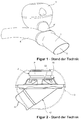
- FIG. 1 shown in a schematic perspective view of the anti-sound system has a sound generator 3 in the form of a solid housing containing an electrodynamic speaker 2 and is connected via a Y-piece 1 to an exhaust system 4.
- the Y-piece 1 has at the foot of the "Y" on an orifice 5 to emit exhaust gas guided in the exhaust system 4 to the outside.
- the thermal load of the recorded in the sound generator 3 speaker 2 is kept low by the guided in the exhaust system 4 exhaust gas. This is necessary because conventional speakers can only work in a range of up to 200 ° C, the temperature of the exhaust gas guided in the exhaust system 4 but can be up to between 400 ° C and 700 ° C.
- FIG. 2 schematically is a sectional view through the sound generator 3 using the example of a voice coil loudspeaker shown.
- the loudspeaker 2 has a permanent magnet 21 and a funnel-shaped membrane 22, which are jointly carried by a loudspeaker basket 23.
- the membrane 22 is radially outwardly connected via an elastic bead (not shown) to the loudspeaker frame 23 and has radially inside a voice coil (not shown), which is guided in bores in the permanent magnet 21.
- an alternating current to the voice coil is via the voice coil due to the Lorentz force exerted a force on the diaphragm 22, which causes them to vibrate.
- the loudspeaker basket 23 is supported radially on the outside by a horn 42, which is connected to the Y-piece 1 via a connecting tube 41.
- the use of the bell mouth 42 is required because the area of the diaphragm 22 of the loudspeaker 2 is greater than the cross-sectional area of the exhaust system 4 in the region of the coupling of the sound. This is necessary to achieve the required sound fluxes.
- the sound generator has a considerable volume of construction. Such is due to numerous restrictive space conditions in the underbody of a vehicle or in the intake system receiving engine compartment of a vehicle only limited available. Since significant noise flows are required in anti-noise systems for vehicles powered by internal combustion engines, it is also not possible to simply reduce the diameter of the loudspeaker. Rather, it is necessary that the area of the diaphragm of the loudspeaker is greater than or equal to the cross-sectional area of the exhaust system or the intake system in the coupling of the sound. This in turn requires the use of a bell tower as a transition between the diaphragm of the speaker and the connector to the exhaust system or intake.
- Embodiments of a sound generator for an anti-noise system for influencing sound waves guided in exhaust systems or intake systems of vehicles powered by internal combustion engines have a housing with a connection opening for the fluid connection of an exhaust system, a loudspeaker frame supported by the housing, a membrane supported by the loudspeaker basket, a permanent magnet supported by the speaker basket, and a voice coil carried by a voice coil bobbin.
- the voice coil is arranged in a magnetic field generated by the permanent magnet and connected to the membrane.
- the membrane is arranged between the connection opening of the housing and the permanent magnet.
- the membrane is funnel-shaped and in particular non-developable funnel-shaped (NAWI membrane) or spherical cap, wherein the tip or top surface of the funnel-shaped membrane or the geometric center of the spherical cap membrane facing away from the permanent magnet.
- the base of the funnel-shaped or kugelkalottenförmigen membrane is thus facing the permanent magnet.
- a distance of the tip or top surface of the funnel-shaped membrane or the geometric center of the spherical cap membrane from the permanent magnet is further spaced than the respective base surface of the membrane.
- Non-developable funnel-shaped or spherical cap-shaped membranes are particularly stiff and thus allow a full-surface and uniform movement of the membrane. Alternatively, however, a cone-shaped membrane is possible.
- the membrane Due to this configuration and arrangement of the membrane, a particularly large amount of space is provided for accommodating the permanent magnet, the voice coil, the voice coil support and possibly a stop damper, which are arranged wholly or partially inside the volume spanned by the diaphragm and the loudspeaker basket.
- the air volume between the membrane and the connection opening can thereby be reduced by between 4% and 6% of the total housing volume in favor of the volume of air located between membrane and housing on the other side of the membrane compared with a conventional construction of a sound generator for an anti-noise system ,
- the overall volume of the speaker compared to a conventional structure can therefore be reduced by between 4% and 6%, in particular, the depth of the speaker can be reduced ,
- a horn provided by the housing at the connection opening is furthermore provided, which can be connected via the connection opening to the intake system or exhaust system of a vehicle operated by internal combustion engine.
- the loudspeaker basket is supported by the housing via the bell.
- the tip or top surface of the funnel-shaped membrane or the geometric center of the spherical cap-shaped membrane is arranged in the horn.
- the horn then support the loudspeaker basket radially outward.
- the horn optionally has the shape of an oblique circular cone whose tip is capped, wherein the top or top surface of the funnel-shaped membrane or the geometric center of the spherical cap membrane a base of the horn penetrates the circular cone described and opens the circular cone at its capped tip into the connection opening of the housing.
- the tip or top surface of the funnel-shaped membrane is arranged in or passes through a horn and / or the connection opening of the housing.
- connection of the loudspeaker basket with the membrane attached to it on the housing is airtight.
- this connection with the housing takes place indirectly via a bell-mouth attached airtight to the housing.
- the membrane divides an inner volume of the housing into a part separated from the exhaust system or intake system and a part in fluid communication with the exhaust system or intake system via the connection opening.
- the membrane is airtight. Furthermore, with the exception of the connection opening, the housing is airtight.
- the two parts of the inner volume of the housing through the membrane (including an existing bead) and the inner wall of the housing and possibly an edge of the speaker basket are hermetically separated from each other.
- the airtightly separated from the connection opening part of the inner volume of the housing thus forms an air cushion acting on the membrane.
- the membrane operates on the back side to a closed volume and on the front side via the connection opening on the exhaust system or intake system.
- This rear closed volume is larger with the same size of the housing compared to conventional sound generators, when the permanent magnet and the voice coil as proposed are arranged inside the volume spanned by the membrane and the loudspeaker frame, so that a ratio of rear volume to front volume increases ,
- the acoustic performance increases with the same volume of construction as with conventional sound generators, so that, conversely, the same acoustic performance as with conventional sound generators can be achieved with a smaller overall volume.
- the loudspeaker basket further carries a stop damper made of elastic material, which is arranged between the membrane or a centrally carried by the membrane, the voice coil covering cap and the permanent magnet in particular centrally in the interior of the voice coil bobbin and fixed to the permanent magnet.
- This damper is dimensioned so that it at deflections of the voice coil and thus the Membrane, which exceed a threshold value, against the membrane and / or centrally disposed in the membrane cap acts.
- the stop damper also carries a centering device, which is connected to the voice coil bobbin or in the region of the voice coil bobbin with the membrane.
- the centering device ensures the return of the membrane to the rest position and the centering of the voice coil relative to the permanent magnet.
- the loudspeaker basket further carries a centering device, which is connected to the voice coil former or in the region of the voice coil carrier with the membrane, thus ensuring the return of the diaphragm to the rest position and the centering of the voice coil with respect to the permanent magnet.
- the permanent magnet is arranged between the loudspeaker frame and the membrane.
- the permanent magnet and the voice coil are arranged inside a volume spanned by the diaphragm and the loudspeaker frame. As a result, the depth of the speaker is reduced. This allows the construction volume of the sound generator at the same To reduce sound flow.
- the membrane is connected to the loudspeaker frame via an airtight bead. This makes it possible to adjust the vibration behavior of the membrane by appropriate choice of material and dimensioning of the bead. Further, bead and membrane are made according to an embodiment of different materials.
- the loudspeaker basket is made of metal or plastic.
- the housing of the sound generator is formed of metal or plastic.
- the housing of the sound generator is formed from two cup-shaped shells, which are soldered, welded, crimped, riveted, glued or screwed together airtight.
- the membrane is made of metal and in particular of aluminum or titanium or of plastic and in particular of aromatic polyamides.
- the permanent magnet has rare earths and in particular neodymium and is in particular formed from a neodymium-iron-boron alloy.
- Embodiments of an anti-noise system for exhaust systems and / or intake systems of an internal combustion engine-operated vehicle have an anti-noise control and at least one sound generator as described above.
- the voice coil of the at least one sound generator is electrically connected to the anti-ballast control.
- the antisound controller is designed to generate a control signal and to the voice coil of the to spend at least one sound generator.
- the control signal is suitable for extinguishing sound inside the exhaust system or intake system at least partially and preferably completely in magnitude and phase when the voice coil is operated with this control signal.
- Embodiments of a motor vehicle include an internal combustion engine with an engine controller, an intake system and an exhaust system in fluid communication with the internal combustion engine, and the antisound system described above.
- the at least one sound generator of the anti-ballast system is in fluid communication with the intake system and / or exhaust system.
- the antisound control of the antisound system is connected to the engine control of the internal combustion engine of the vehicle.
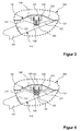
- FIG. 3 schematically is a sectional view through the sound generator 103 according to a first embodiment of the invention shown.
- the sound generator 103 has a housing 131, which in its interior receives a modified voice coil speaker 102.
- the loudspeaker 102 comprises a permanent magnet 121 made of neodymium-iron-boron alloy and a cone-shaped membrane 122 made of plastic, which are jointly carried by a loudspeaker basket 123 made of sheet steel.
- the conical membrane 122 is connected at its base radially outward via an elastic bead 127 made of plastic with the loudspeaker frame 123.
- the top surface of the cone-shaped membrane 122 is closed at the center by a cap 124.
- a voice coil bobbin 125 which carries a voice coil 126, is attached to the diaphragm 122.
- the voice coil 126 is disposed in a DC magnetic field generated by the permanent magnet 121.
- the permanent magnet has a corresponding recess.
- the permanent magnet 121 and the voice coil bobbin 125 are arranged with the voice coil 126 within the spanned by the loudspeaker frame 123 and the membrane 122 volume, so that the permanent magnet 121 is partially disposed within the cone 122 defined by the cone ', whereby a compact volume of the Speaker 102 is reached. Accordingly, the sound generator 103 can be made compact.
- the top surface of the cone-shaped membrane 122 with the cap 124 is thus facing away from the loudspeaker basket 123 and also the permanent magnet 121, the base surface of the cone-shaped membrane 122 faces the loudspeaker basket 123 and also the permanent magnet 121.
- the cap 124 comes into abutment against the stop damper 128, so that a vibration of the diaphragm 122 is damped.
- the loudspeaker basket 123 is radially outwardly connected to an inner wall of the housing 131 of the sound generator 103, and is airtight connected to a horn 142, in which the tip of the membrane 122 projects.
- the bell mouth 142 is connectable via a connection opening 132 of the sound generator 103 and a connecting pipe 141 with the intake system and / or exhaust system of a vehicle operated by internal combustion engine. Since the connection of the cap 124 to the membrane 122 and the connection of the membrane 122 on the bead 127 on the speaker basket 123 airtight, the speaker 102 so together with the horn 142 divides the internal volume of the sound generator 103 into two hermetically separate parts.
- the diaphragm 122 of the speaker 102 is disposed in the installed state of the speaker 102 between the connection opening 132 of the sound generator 103 and the permanent magnet 121, and the permanent magnet 121 between the diaphragm 122 and the loudspeaker frame 123 is arranged.
- the voice coil bobbin 125 with the voice coil 126 and the permanent magnet 121 are hermetically separated from the corrosive exhaust gas by the diaphragm 122.
- FIG. 4 schematically is a sectional view through the sound generator 103 according to a second embodiment of the invention shown. Since this second embodiment of the above in connection with FIG. 3 is very similar to the embodiment described below, only on Differences received and otherwise referred to the above statements.
- the second embodiment differs from the first embodiment described above in that the stopper damper 128 further carries a centering device 129 in the form of radially oriented plastic rods, which is connected to the voice coil bobbin 125.
- Another centering device 143 in the form of a spider is spanned between the loudspeaker frame 123 and the voice coil bobbin 125.
- the centering devices 129, 143 ensure the return of the diaphragm 122 to the rest position and the centering of the voice coil 126 relative to the permanent magnet 121. It is emphasized that one or both centering devices 129, 143 can be dispensed with.
- FIG. 5 There is shown schematically an antisound system 7 which uses the sound generator 103 described above.
- a first sound generator 103 is connected in the region of an orifice 5 via a Y-piece 1 and a connecting pipe 141 to an exhaust system 4 of a vehicle. About the mouth 5 guided exhaust gas is discharged to the outside in the exhaust system 4.
- a first error microphone 9 is provided in the form of a pressure sensor.
- the error microphone 9 measures pressure fluctuations and thus sound inside the Y-piece 1 in a section downstream of a region in which the fluid connection between the exhaust system 9 and the sound generator 103 takes place. It is emphasized, however, that the error microphone 9 is only optional.
- a second sound generator 103 'with a second Speaker 102 ' is connected to an intake system 10 of the vehicle. Upstream of a region in which the fluid connection between the intake system 10 and the sound generator 103 'takes place, a second error microphone 9' is arranged in the intake system 10. Again, it is emphasized that the error microphone 9 'is only optional.
- the flow direction of the guided in the intake system 10 and the air guided in the exhaust system 4 exhaust gas is shown by arrows.
- the loudspeakers 102, 102 'of the sound generators 103, 103' and the error microphones 9, 9 ' are electrically connected to an anti-noise controller 8. Further, the anti-noise controller 8 is connected via a CAN bus to a motor controller 61 of an internal combustion engine 6. It is emphasized that the present invention is not limited to a CAN bus.
- the exhaust system 4 may further comprise at least one arranged between the engine 6 and the Y-piece 1 catalyst (not shown) for cleaning the emitted from the engine 6 and guided in the exhaust system 4 exhaust gas.
- FIG. 6 schematically a motor vehicle with an internal combustion engine 6, an exhaust system 4 and the above-described anti-noise system 7 is shown.
- the sound generators and the speakers of the anti-noise system are in FIG. 6 not shown separately.
- a cone-shaped diaphragm has been used for the speaker as above, the present invention is not limited thereto.
- a NAWI membrane can be used.
- a NAWI membrane is understood to mean a membrane whose shape can not be developed into a flat surface.
Description
- Die Erfindung betrifft einen Schallerzeuger für ein Antischall-System zur Beeinflussung von in Abgasanlagen von verbrennungsmotorisch betriebenen Fahrzeugen geführten Schallwellen (Abgasgeräuschen) und/oder zur Beeinflussung von in Ansauganlagen von Verbrennungsmotoren geführten Schallwellen (Ansauggeräuschen).
- Unabhängig von der Bauform eines Verbrennungsmotors (beispielsweise Hubkolbenmotor, Rotationskolbenmotor oder Freikolbenmotor) werden infolge der hintereinander ablaufenden Arbeitstakte (insbesondere Ansaugen und Verdichten eines Kraftstoff-Luftgemischs, Arbeiten und Ausstoßen des verbrannten Kraftstoff-Luftgemischs) Geräusche erzeugt. Diese durchlaufen zum einen als Körperschall den Verbrennungsmotor und werden außen am Verbrennungsmotor als Luftschall abgestrahlt. Zum anderen durchlaufen die Geräusche als Luftschall zusammen mit dem verbrannten Kraftstoff-Luftgemisch eine mit dem Verbrennungsmotor in Fluidverbindung stehende Abgasanlage.
- Diese Geräusche werden häufig als nachteilig empfunden. Zum einen gibt es gesetzliche Vorgaben zum Lärmschutz, die von Herstellern von verbrennungsmotorisch betriebenen Fahrzeugen einzuhalten sind. Diese gesetzlichen Vorgaben geben in der Regel einen im Betrieb des Fahrzeugs maximal zulässigen Schalldruck vor. Zum anderen versuchen Hersteller, den von ihnen erzeugten verbrennungsmotorisch betriebenen Fahrzeugen eine charakteristische Geräuschentwicklung aufzuprägen, welche zum Image des jeweiligen Herstellers passen und die Kunden ansprechen soll. Diese charakteristische Geräuschentwicklung lässt sich bei modernen Motoren mit geringem Hubraum häufig nicht mehr auf natürlichem Wege sicherstellen.
- Die den Verbrennungsmotor als Körperschall durchlaufenden Geräusche lassen sich gut dämmen und stellen daher in der Regel kein Problem hinsichtlich des Lärmschutzes dar.
- Die eine Abgasanlage des Verbrennungsmotors zusammen mit dem verbrannten Kraftstoff-Luftgemisch als Luftschall durchlaufenden Geräusche werden durch vor der Mündung der Abgasanlage angeordnete Schalldämpfer reduziert, welche ggf. vorhandenen Katalysatoren nachgeschaltet sind. Derartige Schalldämpfer können beispielsweise nach dem Absorptions- und/oder Reflexionsprinzip arbeiten. Beide Arbeitsweisen weisen den Nachteil auf, dass sie ein vergleichsweise großes Volumen beanspruchen und dem verbrannten Kraftstoff-Luftgemisch einen relativ hohen Widerstand entgegen setzen, wodurch der Gesamtwirkungsgrad des Fahrzeuges sinkt und der Kraftstoffverbrauch steigt.
- Als Alternative oder zur Ergänzung von Schalldämpfern werden seit einiger Zeit sogenannte Antischall-Systeme entwickelt, die dem vom Verbrennungsmotor erzeugten und in der Abgasanlage geführten Luftschall einen elektroakustisch erzeugten Anti-Schall überlagern. Derartige Systeme sind beispielsweise aus den Dokumenten
US 4,177,874 ,US 5,229,556 ,US 5,233,137 ,US 5,343,533 ,US 5,336,856 ,US 5,432,857 ,US 5,600,106 ,US 5,619,020 ,EP 0 373 188 ,EP 0 674 097 ,EP 0 755 045 ,EP 0 916 817 ,EP 1 055 804 ,EP 1 627 996 ,DE 197 51 596 ,DE 10 2006 042 224 ,DE 10 2008 018 085 undDE 10 2009 031 848 bekannt. - Derartige Antischall-Systeme verwenden üblicherweise einen sogenannten Filtered-x Least mean squares (FxLMS) Algorithmus, der versucht, den in der Abgasanlage geführten Luftschall durch Ausgabe von Schall über wenigstens einen mit der Abgasanlage in Fluidverbindung stehenden Lautsprecher auf Null (im Falle der Schallauslöschung) oder einen vorgegebenen Schwellwert (im Falle der Schallbeeinflussung) zu regeln. Zum Erzielen einer vollständigen destruktiven Interferenz der Schallwellen des in der Abgasanlage geführten Luftschalls und des vom Lautsprecher erzeugten Anti-Schalls müssen die vom Lautsprecher herrührenden Schallwellen nach Amplitude und Frequenz den in der Abgasanlage geführten Schallwellen entsprechen, relativ zu diesen jedoch eine Phasenverschiebung von 180 Grad aufweisen. Entsprechen sich die in der Abgasanlage geführten Schallwellen des Luftschalls und die vom Lautsprecher erzeugten Schallwellen des Anti-Schalls zwar in der Frequenz, und weisen sie relativ zueinander eine Phasenverschiebung von 180 Grad auf, entsprechen sich die Schallwellen aber nicht in der Amplitude, kommt es nur zu einer Abschwächung der in der Abgasanlage geführten Schallwellen des Luftschalls. Für jedes Frequenzband des im Abgasrohr geführten Luftschalls wird der Anti-Schall mittels des FxLMS-Algorithmus gesondert berechnet, indem eine geeignete Frequenz und Phasenlage von zwei zueinander um 90 Grad verschobenen Sinusschwingungen bestimmt wird, und die erforderlichen Amplituden für diese Sinusschwingungen berechnet werden. Das Ziel von Antischall-Systemen ist es, dass die Schallauslöschung bzw. Schallbeeinflussung zumindest außerhalb, ggf. aber auch innerhalb der Abgasanlage hörbar und messbar ist. Die Bezeichnung Anti-Schall dient in diesem Dokument zur Unterscheidung zu dem in der Abgasanlage geführten Luftschall. Für sich alleine betrachtet handelt es sich bei Anti-Schall um gewöhnlichen Luftschall. Es wird betont, dass die vorliegende Erfindung nicht auf die Verwendung eines FxLMS-Algorithmus beschränkt ist.
- Auch in den Ansauganlagen von Verbrennungskraftmaschinen treten Schallwellen auf, die als störend empfunden werden können. Diese Schallwellen werden sowohl durch Turbulenzen in der Luftströmung als auch durch den Verbrennungsmotor selber hervorgerufen. Die Ansauganlage, die auch als Ansaugtrakt bezeichnet wird, umfasst alle Verbrennungsluft führenden Bauteile einer Verbrennungskraftmaschine, die sich vor der Brennkammer oder dem Brennraum befinden.
- Ein Antischall-System zur Beeinflussung von in einer Abgasanlage eines verbrennungsmotorisch betriebenen Fahrzeugs geführten Schallwellen ist aus dem Dokument
EP 2 108 791 A1 vorbekannt und wird im Folgenden anhand derFiguren 1 und 2 beschrieben. - Das in
Figur 1 in schematischer Perspektivansicht gezeigte Antischall-System weist einen Schallerzeuger 3 in Form eines festen Gehäuses auf, welches einen elektrodynamischen Lautsprecher 2 enthält und über ein Y-Stück 1 an eine Abgasanlage 4 angebunden ist. Das Y-Stück 1 weist am Fuß des "Y" eine Mündung 5 auf, um in der Abgasanlage 4 geführtes Abgas nach außen abzugeben. Durch die Anbindung über das Y-Stück wird die thermische Belastung des im Schallerzeuger 3 aufgenommenen Lautsprechers 2 durch das in der Abgasanlage 4 geführte Abgas gering gehalten. Dies ist erforderlich, da herkömmliche Lautsprecher nur in einem Bereich von bis maximal 200°C arbeiten können, die Temperatur des in der Abgasanlage 4 geführten Abgases aber bis zu zwischen 400°C und 700°C betragen kann. - In
Figur 2 ist schematisch eine Schnittansicht durch den Schallerzeuger 3 am Beispiel eines Tauchspulenlautsprechers gezeigt. Ersichtlich weist der Lautsprecher 2 einen Permanentmagneten 21 und eine trichterförmige Membran 22 auf, welche gemeinsam von einem Lautsprecherkorb 23 getragen werden. Dabei ist die Membran 22 radial außen über eine elastische Sicke (nicht gezeigt) mit dem Lautsprecherkorb 23 verbunden und weist radial innen eine Schwingspule (nicht gezeigt) auf, welche in Bohrungen in dem Permanentmagneten 21 geführt wird. Durch Anlegen eines Wechselstroms an die Schwingspule wird über die Schwingspule aufgrund der Lorentzkraft eine Kraft auf die Membran 22 ausgeübt, die diese zum Schwingen veranlasst. Der Lautsprecherkorb 23 ist radial außen von einem Schalltrichter 42 gehaltert, welcher über ein Verbindungsrohr 41 mit dem Y-Stück 1 verbunden ist. Die Verwendung des Schalltrichters 42 ist erforderlich, da die Fläche der Membran 22 des Lautsprechers 2 größer der Querschnittsfläche der Abgasanlage 4 im Bereich der Einkoppelung des Schalls ist. Dies ist erforderlich, um die benötigten Schallflüsse zu erreichen. - Bei dem vorstehend beschriebenen Aufbau ist es nachteilig, dass der Schallerzeuger ein erhebliches Bauvolumen aufweist. Ein solches steht auf Grund zahlreicher restriktiver Bauraumbedingungen im Unterboden eines Fahrzeugs bzw. im die Ansauganlage aufnehmenden Motorraum eines Fahrzeugs nur eingeschränkt zur Verfügung. Da in Antischall-Systemen für verbrennungsmotorisch betriebene Fahrzeuge erhebliche Schallflüsse benötigt werden, ist es auch nicht möglich, einfach den Durchmesser des Lautsprechers zu verringern. Vielmehr ist es erforderlich, dass die Fläche der Membran des Lautsprechers größer oder gleich der Querschnittsfläche der Abgasanlage bzw. der Ansauganlage im Bereich der Einkoppelung des Schalls ist. Dies bedingt wiederum die Verwendung eines Schalltrichters als Übergang zwischen der Membran des Lautsprechers und dem Verbindungsstück zur Abgasanlage bzw. Ansauganlage.
- Schallerzeuger mit den Merkmalen des Oberbegriffs des unabhängigen Anspruchs 1 sind aus den Dokumenten
US 2005/152576 A1 ,US 2005/152569 A1 undUS 2010/322461 A1 bekannt. - Es ist Aufgabe der vorliegenden Erfindung, einen Schallerzeuger für ein Antischall-System zur Beeinflussung von Abgasgeräuschen oder Ansauggeräuschen von verbrennungsmotorisch betriebenen Fahrzeugen bereitzustellen, welcher ein kompaktes Bauvolumen aufweist und gleichwohl einen hohen Schallfluss bereitstellt.
- Die vorstehende Aufgabe wird durch die Kombination der Merkmale des unabhängigen Anspruchs 1 gelöst. Bevorzugte Weiterbildungen finden sich in den Unteransprüchen.
- Ausführungsformen eines Schallerzeugers für ein Antischall-System zur Beeinflussung von in Abgasanlagen oder Ansauganlagen von verbrennungsmotorisch betriebenen Fahrzeugen geführten Schallwellen weisen ein Gehäuse mit einer Anschlussöffnung zur fluiden Anbindung einer Abgasanlage bzw. Ansauganlage, einen von dem Gehäuse gehalterten Lautsprecherkorb, eine von dem Lautsprecherkorb gehalterte Membran, einen von dem Lautsprecherkorb gehalterten Permanentmagneten, und eine von einem Schwingspulenträger getragene Schwingspule auf. Die Schwingspule ist in einem von dem Permanentmagneten erzeugten magnetischen Gleichfeld angeordnet und mit der Membran verbunden. Die Membran ist zwischen der Anschlussöffnung des Gehäuses und dem Permanentmagneten angeordnet. Die Membran ist trichterförmig und insbesondere nicht-abwickelbar trichterförmig (NAWI-Membran) oder kugelkalottenförmig, wobei die Spitze bzw. Deckfläche der trichterförmigen Membran bzw. der geometrische Mittelpunkt der kugelkalottenförmigen Membran dem Permanentmagneten abgewandt ist. Die Grundfläche der trichterförmigen oder kugelkalottenförmigen Membran ist somit dem Permanentmagneten zugewandt. Somit ist ein Abstand der Spitze bzw. Deckfläche der trichterförmigen Membran bzw. des geometrischen Mittelpunkts der kugelkalottenförmigen Membran von dem Permanentmagneten weiter beabstandet, als die jeweilige Grundfläche der Membran. Nicht-abwickelbare trichterförmige oder kugelkalottenförmige Membranen sind besonders steif und erlauben so eine ganzflächige und gleichmäßige Bewegung der Membran. Alternativ ist aber auch eine konusförmige Membran möglich.
- Aufgrund dieser Ausgestaltung und Anordnung der Membran wird besonders viel Raum für die Aufnahme des Permanentmagneten, der Schwingspule, des Schwingspulenträgers und ggf. eines Anschlagdämpfers bereit gestellt, welche ganz oder teilweise im Inneren des von der Membran und dem Lautsprecherkorb aufgespannten Volumens angeordnet sind. Gemäß einer Ausführungsform kann hierdurch das zwischen Membran und Anschlussöffnung liegende Luftvolumen zugunsten des auf der anderen Seite der Membran zwischen Membran und Gehäuse befindlichen Luftvolumens verglichen mit einem herkömmlichen Aufbau eines Schallerzeugers für ein Antischall-System um zwischen 4% und 6% des gesamten Gehäusevolumens reduziert werden. Bei gleichem Luftvolumen zwischen Membran und Gehäuse auf der Seite der Membran, die der Anschlussöffnung abgewandt ist, kann das Bauvolumen des Lautsprechers verglichen mit einem herkömmlichen Aufbau daher insgesamt um zwischen 4% und 6% reduziert werden, wobei insbesondere die Bautiefe des Lautsprechers reduziert werden kann. Somit ist es möglich, das Bauvolumen des Schallerzeugers bei gleichem Schallfluss zu reduzieren.
- Erfindungsgemäß ist weiter ein von dem Gehäuse an der Anschlussöffnung gehalterter Schalltrichter vorgesehen, der über die Anschlussöffnung mit der Ansauganlage oder Abgasanlage eines verbrennungsmotorisch betriebenen Fahrzeugs verbindbar ist. Der Lautsprecherkorb wird über den Schalltrichter von dem Gehäuse gehaltert. Die Spitze oder Deckfläche der trichterförmigen Membran oder der geometrische Mittelpunkt der kugelkalottenförmigen Membran ist in dem Schalltrichter angeordnet.
- Fakultativ kann dann der Schalltrichter den Lautsprecherkorb radial außen haltern.
- Weiter kann dann der Schalltrichter fakultativ die Form eines schrägen Kreiskegels aufweist, dessen Spitze gekappt ist, wobei die Spitze oder Deckfläche der trichterförmigen Membran oder der geometrische Mittelpunkt der kugelkalottenförmigen Membran eine Grundfläche des von dem Schalltrichter beschriebenen Kreiskegels durchdringt und wobei der Kreiskegel an seiner gekappten Spitze in die Anschlussöffnung des Gehäuses mündet.
- Gemäß einer Ausführungsform ist die Spitze bzw. Deckfläche der trichterförmigen Membran in einem Schalltrichter und/oder der Anschlussöffnung des Gehäuses angeordnet oder durchdringt diese.
- Gemäß einer Ausführungsform erfolgt die Verbindung des Lautsprecherkorbes mit der daran befestigten Membran an dem Gehäuse luftdicht. Gemäß einer Ausführungsform erfolgt diese Verbindung mit dem Gehäuse mittelbar über einen luftdicht an dem Gehäuse befestigten Schalltrichter. Weiter teilt die Membran ein Innenvolumen des Gehäuses in einen von der Abgasanlage bzw. Ansauganlage abgetrennten Teil und einen mit der Abgasanlage bzw. Ansauganlage über die Anschlussöffnung in Fluidverbindung befindlichen Teil auf.
- Da sich nur die Membran und ggf. ein Rand des Lautsprecherkorbes in dem Teil des Gehäuses befinden, welcher Teil sich mit der Abgasanlage bzw. Ansauganlage über die Anschlussöffnung in Fluidverbindung befindet, sind auch nur diese Elemente dem heißen und mit korrosiven Chemikalien belasteten Abgas bzw. der ggf. feuchten und/oder mit Schadstoffen belasteten angesaugten Luft ausgesetzt. Somit müssen neben der Innenwand des Gehäuses nur diese Elemente aus einem Material gebildet sein, welches dem Abgas und einem evtl. entstehenden Kondensat bzw. der Feuchtigkeit und Schadstoffen der angesaugten Luft widerstehen kann. Die übrigen Elemente des Schallerzeugers und insbesondere die empfindliche Schwingspule, welche aufgrund ohmscher Verluste ohnehin einer gewissen Temperaturbelastung ausgesetzt ist, werden hingegen durch die Membran und die Innenwand des Gehäuses von dem Abgas bzw. der angesaugten Luft abgeschirmt. Hierdurch wird auch die Gefahr eines Kurzschlusses der Schwingspule durch entstehendes Kondensat des Abgases bzw. Luftfeuchtigkeit der angesaugten Luft verringert.
- Gemäß einer Ausführungsform ist die Membran luftdicht. Weiter ist das Gehäuse mit Ausnahme der Anschlussöffnung luftdicht. Somit sind die beiden Teile des Innenvolumens des Gehäuses durch die Membran (einschließlich einer vorhandenen Sicke) und die Innenwand des Gehäuses sowie ggf. einen Rand des Lautsprecherkorbes luftdicht voneinander getrennt.
- Der von der Anschlussöffnung luftdicht abgetrennte Teil des Innenvolumens des Gehäuses bildet so ein auf die Membran wirkendes Luftpolster. Somit arbeitet die Membran rückseitig auf ein geschlossenes Volumen und vorderseitig über die Anschlussöffnung auf die Abgasanlage bzw. Ansauganlage. Dieses rückseitige geschlossene Volumen ist bei gleicher Größe des Gehäuses verglichen mit herkömmlichen Schallerzeugern größer, wenn der Permanentmagnet und die Schwingspule wie vorgeschlagen im Inneren des von der Membran und dem Lautsprecherkorb aufgespannten Volumens angeordnet sind, so dass sich ein Verhältnis von rückseitigem Volumen zu vorderseitigem Volumen vergrößert. In der Folge vergrößert sich bei gleichem Bauvolumen wie bei herkömmlichen Schallerzeugern die akustische Leistungsfähigkeit, so dass umgekehrt die gleiche akustische Leistungsfähigkeit wie bei herkömmlichen Schallerzeugern bei kleinerem Bauvolumen erzielt werden kann.
- Gemäß einer Ausführungsform trägt der Lautsprecherkorb weiter einen Anschlagdämpfer aus elastischem Material, welcher zwischen der Membran oder einer insbesondere mittig von der Membran getragenen, die Schwingspule abdeckenden Abdeckkappe und dem Permanentmagneten insbesondere mittig im Inneren des Schwingspulenträgers angeordnet und an dem Permanentmagneten befestigt ist. Dieser Anschlagdämpfer ist so dimensioniert, dass er bei Auslenkungen der Schwingspule und damit der Membran, die einen Schwellwert übersteigen, gegen die Membran und/oder eine mittig in der Membran angeordnete Abdeckkappe wirkt. Durch das Vorsehen des Anschlagdämpfers wird ein hartes Anschlagen der Membran und/oder der Schwingspule und/oder des Schwingspulenträgers am Permanentmagneten bei übermäßiger Auslenkung vermieden, oder der Anschlag zumindest gedämpft. Damit wird eine Beschädigung des Schallerzeugers im Überlastungsfall vermieden.
- Gemäß einer Ausführungsform trägt der Anschlagdämpfer ferner eine Zentriereinrichtung, welche mit dem Schwingspulenträger oder im Bereich des Schwingspulenträgers mit der Membran verbunden ist. Die Zentriereinrichtung stellt die Rückführung der Membran in die Ruhelage sowie die Zentrierung der Schwingspule gegenüber dem Permanentmagneten sicher.
- Gemäß einer Ausführungsform trägt der Lautsprecherkorb ferner eine Zentriereinrichtung, welche mit dem Schwingspulenträger oder im Bereich des Schwingspulenträgers mit der Membran verbunden ist, und so die Rückführung der Membran in die Ruhelage sowie die Zentrierung der Schwingspule gegenüber dem Permanentmagneten sicher stellt.
- Es wird betont, dass auf das Vorsehen einer Zentriereinrichtung verzichtet werden kann, wenn eine weitgehend reibungslose Führung der Schwingspule im Permanentmagneten erfolgt.
- Gemäß einer Ausführungsform ist der Permanentmagnet zwischen Lautsprecherkorb und Membran angeordnet.
- Somit sind bei diesem Schallerzeuger der Permanentmagnet und die Schwingspule im Inneren eines von der Membran und dem Lautsprecherkorb aufgespannten Volumens angeordnet. Hierdurch wird die Bautiefe des Lautsprechers reduziert. Dies erlaubt es, das Bauvolumen des Schallerzeugers bei gleichem Schallfluss zu reduzieren.
- Gemäß einer Ausführungsform ist die Membran über eine luftdichte Sicke mit dem Lautsprecherkorb verbunden. Dies erlaubt es, das Schwingungsverhalten der Membran durch entsprechende Materialwahl und Dimensionierung der Sicke einzustellen. Weiter sind Sicke und Membran gemäß einer Ausführungsform aus unterschiedlichen Materialien gefertigt.
- Gemäß einer Ausführungsform ist der Lautsprecherkorb aus Metall oder Kunststoff gebildet.
- Gemäß einer Ausführungsform ist das Gehäuse des Schallerzeugers aus Metall oder Kunststoff gebildet.
- Gemäß einer Ausführungsform ist das Gehäuse des Schallerzeugers aus zwei topfförmigen Schalen gebildet, welche miteinander luftdicht verlötet, verschweißt, verbördelt, vernietet, verklebt oder verschraubt sind.
- Gemäß einer Ausführungsform ist die Membran aus Metall und insbesondere aus Aluminium oder Titan oder aus Kunststoff und insbesondere aus aromatischen Polyamiden gebildet.
- Gemäß einer Ausführungsform weist der Permanentmagnet Seltene Erden und insbesondere Neodym auf und ist insbesondere aus einer Neodym-Eisen-Bor Legierung gebildet.
- Ausführungsformen eines Antischall-Systems für Abgasanlagen und/oder Ansauganlagen eines verbrennungsmotorisch betriebenen Fahrzeugs weisen eine Antischall-Steuerung und wenigstens einen Schallerzeuger wie vorstehend beschrieben auf. Dabei ist die Schwingspule des wenigstens einen Schallerzeugers elektrisch mit der Antischall-Steuerung verbunden. Die Antischall-Steuerung ist ausgebildet, ein Steuersignal zu erzeugen und an die Schwingspule des wenigstens einen Schallerzeugers auszugeben. Das Steuersignal ist geeignet, Schall im Inneren der Abgasanlage bzw. Ansauganlage zumindest teilweise und bevorzugt vollständig in Betrag und Phase auszulöschen, wenn die Schwingspule mit diesem Steuersignal betrieben wird.
- Ausführungsformen eines Kraftfahrzeugs weisen einen Verbrennungsmotor mit einer Motorsteuerung, eine Ansauganlage und eine Abgasanlage, die mit dem Verbrennungsmotor in Fluidverbindung stehen, und das vorstehend beschriebene Antischall-System auf. Dabei steht der wenigstens eine Schallerzeuger des Antischall-Systems mit der Ansauganlage und/oder Abgasanlage in Fluidverbindung. Weiter ist die Antischall-Steuerung des Antischall-Systems mit der Motorsteuerung des Verbrennungsmotors des Fahrzeugs verbunden.
- Weiter wird darauf hingewiesen, dass die in dieser Beschreibung und den Ansprüchen zur Aufzählung von Merkmalen verwendeten Begriffe "umfassen", "aufweisen", "beinhalten", "enthalten" und "mit", sowie deren grammatikalische Abwandlungen, generell als nichtabschließende Aufzählung von Merkmalen, wie z. B. Verfahrensschritten, Einrichtungen, Bereichen, Größen und dergleichen aufzufassen sind, und in keiner Weise das Vorhandensein anderer oder zusätzlicher Merkmale oder Gruppierungen von anderen oder zusätzlichen Merkmalen ausschließen.
- Weitere Merkmale der Erfindung ergeben sich aus der nachfolgenden Beschreibung von Ausführungsbeispielen in Verbindung mit den Ansprüchen sowie den Figuren. In den Figuren werden gleiche bzw. ähnliche Elemente mit gleichen bzw. ähnlichen Bezugszeichen bezeichnet. Es wird darauf hingewiesen, dass die Erfindung nicht auf die Ausführungsformen der beschriebenen Ausführungsbeispiele beschränkt, sondern durch den Umfang der beiliegenden Patentansprüche bestimmt ist. Insbesondere können die einzelnen Merkmale bei erfindungsgemäßen Ausführungsformen in anderer Anzahl und Kombination als bei den untenstehend angeführten Beispielen verwirklicht sein. Bei der nachfolgenden Erläuterung einiger Ausführungsbeispiele der Erfindung wird auf die beiliegenden Figuren Bezug genommen, von denen
- Figur 1
- schematisch eine perspektivische Ansicht eines Antischall-Systems nach dem Stand der Technik zeigt;
- Figur 2
- schematisch einen Querschnitt durch einen Schallerzeuger eines Antischall-Systems nach dem Stand der Technik zeigt;
- Figur 3
- schematisch einen Querschnitt durch einen Schallerzeuger eines Antischall-Systems gemäß einer ersten Ausführungsform der Erfindung zeigt;
- Figur 4
- schematisch einen Querschnitt durch einen Schallerzeugers eines Antischall-Systems gemäß einer zweiten Ausführungsform der Erfindung zeigt;
- Figur 5
- schematisch ein Blockdiagramm einer Antischall-Steuerung eines Antischall-Systems gemäß einer Ausführungsform der Erfindung zeigt; und
- Figur 6
- schematisch ein Kraftfahrzeug zeigt, in welches das erfindungsgemäße Antischall-System integriert ist.
- In
Figur 3 ist schematisch eine Schnittansicht durch den Schallerzeuger 103 gemäß einer ersten Ausführungsform der Erfindung gezeigt. - Der Schallerzeuger 103 weist ein Gehäuse 131 auf, welches in seinem Inneren einen modifizierten Tauchspulenlautsprecher 102 aufnimmt. Der Lautsprecher 102 weist einen Permanentmagneten 121 aus Neodym-Eisen-Bor Legierung und eine konusförmige Membran 122 aus Kunststoff auf, welche gemeinsam von einem Lautsprecherkorb 123 aus Stahlblech getragen werden. Dabei ist die konusförmige Membran 122 an ihrer Grundfläche radial außen über eine elastische Sicke 127 aus Kunststoff mit dem Lautsprecherkorb 123 verbunden. Die Deckfläche der konusförmigen Membran 122 ist mittig durch eine Abdeckkappe 124 verschlossen. Im Bereich der Abdeckkappe 124 ist an der Membran 122 ein Schwingspulenträger 125 befestigt, welcher eine Schwingspule 126 trägt. Die Schwingspule 126 ist in einem von dem Permanentmagneten 121 erzeugten magnetischen Gleichfeld angeordnet. Hierfür weist der Permanentmagnet eine entsprechende Ausnehmung auf. Durch Anlegen eines Wechselstroms an die Schwingspule 126, wird über die Schwingspule 126 aufgrund der Lorentzkraft eine Kraft auf die Membran 122 ausgeübt, die diese zum Schwingen veranlasst.
- Dabei sind der Permanentmagnet 121 und der Schwingspulenträger 125 mit der Schwingspule 126 innerhalb des von dem Lautsprecherkorb 123 und der Membran 122 aufgespannten Volumens angeordnet, so dass der Permanentmagnet 121 teilweise innerhalb des von der Membran 122 festsgelegten Konus' angeordnet ist, wodurch ein kompaktes Bauvolumen des Lautsprechers 102 erreicht wird. Entsprechend kann auch der Schallerzeuger 103 kompakt ausgebildet werden. Die Deckfläche der konusförmigen Membran 122 mit der Abdeckkappe 124 ist somit dem Lautsprecherkorb 123 und auch dem Permanentmagneten 121 abgewandt, die Grundfläche der konusförmigen Membran 122 ist dem Lautsprecherkorb 123 und auch dem Permanentmagneten 121 zugewandt.
- Weiter ist zwischen der Membran 122 und dem Permanentmagneten 121 ein Anschlagdämpfer 128 aus Schaumgummi angeordnet, der an dem Permanentmagneten 121 befestigt ist und in Ruhelage der Membran 122 von der Abdeckkappe 124 beabstandet ist. Bei übermäßiger Auslenkung der Membran 122 kommt die Abdeckkappe 124 in Anlage an den Anschlagdämpfer 128, so dass eine Schwingung der Membran 122 gedämpft wird.
- Der Lautsprecherkorb 123 ist radial außen mit einer Innenwand des Gehäuses 131 des Schallerzeugers 103 verbunden, und ist luftdicht mit einem Schalltrichter 142 verbunden, in welchen die Spitze der Membran 122 hineinragt. Der Schalltrichter 142 ist über eine Anschlussöffnung 132 des Schallerzeugers 103 und ein Verbindungsrohr 141 mit der Ansauganlage und/oder Abgasanlage eines verbrennungsmotorisch betriebenen Fahrzeugs verbindbar. Da auch die Verbindung der Abdeckkappe 124 an der Membran 122 und die Anbindung der Membran 122 über die Sicke 127 an dem Lautsprecherkorb 123 luftdicht erfolgt, teilt der Lautsprecher 102 so zusammen mit dem Schalltrichter 142 das Innenvolumen des Schallerzeugers 103 in zwei voneinander hermetisch getrennte Teile.
- Somit ist die Membran 122 des Lautsprechers 102 in eingebautem Zustand der Lautsprechers 102 zwischen der Anschlussöffnung 132 des Schallerzeugers 103 und dem Permanentmagneten 121 angeordnet, und ist der Permanentmagnet 121 zwischen Membran 122 und Lautsprecherkorb 123 angeordnet.
- Damit sind der Schwingspulenträger 125 mit der Schwingspule 126 und der Permanentmagnet 121 durch die Membran 122 hermetisch von dem korrosiven Abgas abgetrennt.
- In
Figur 4 ist schematisch eine Schnittansicht durch den Schallerzeuger 103 gemäß einer zweiten Ausführungsform der Erfindung gezeigt. Da diese zweite Ausführungsform der vorstehend in Verbindung mitFigur 3 beschriebenen Ausführungsform sehr ähnlich ist, wird im Folgenden nur auf Unterschiede eingegangen und ansonsten auf die vorstehenden Ausführungen verwiesen. - Die zweite Ausführungsform unterscheidet sich von der vorstehend beschriebenen ersten Ausführungsform dadurch, dass der Anschlagdämpfer 128 ferner eine Zentriereinrichtung 129 in Form radial orientierter Kunststoffstäbchen trägt, welche mit dem Schwingspulenträger 125 verbunden ist. Eine weitere Zentriereinrichtung 143 in Form einer Zentrierspinne ist zwischen dem Lautsprecherkorb 123 und dem Schwingspulenträger 125 aufgespannt. Die Zentriereinrichtungen 129, 143 stellen die Rückführung der Membran 122 in die Ruhelage sowie die Zentrierung der Schwingspule 126 gegenüber dem Permanentmagneten 121 sicher. Es wird betont, dass auf eine oder beide Zentriereinrichtungen 129, 143 verzichtet werden kann.
- In
Figur 5 ist schematisch ein Antischall-System 7 gezeigt, welches den vorstehend beschriebenen Schallerzeuger 103 verwendet. - Ein erster Schallerzeuger 103 ist im Bereich einer Mündung 5 über ein Y-Stück 1 und ein Verbindungsrohr 141 an eine Abgasanlage 4 eines Fahrzeugs angebunden. Über die Mündung 5 wird in der Abgasanlage 4 geführtes Abgas nach außen abgegeben.
- An dem Y-Stück 1 ist ein erstes Fehlermikrofon 9 in Form eines Drucksensors vorgesehen. Das Fehlermikrofon 9 misst Druckschwankungen und damit Schall im Inneren des Y-Stücks 1 in einem Abschnitt stromabwärts eines Bereichs, in dem die fluide Anbindung zwischen Abgasanlage 9 und Schallerzeuger 103 erfolgt. Es wird jedoch betont, dass das Fehlermikrofon 9 nur optional ist.
- Ein zweiter Schallerzeuger 103' mit einem zweiten Lautsprecher 102' ist an eine Ansauganlage 10 des Fahrzeugs angebunden. Stromaufwärts eines Bereichs, in dem die fluide Anbindung zwischen Ansauganlage 10 und Schallerzeuger 103' erfolgt, ist in der Ansauganlage 10 ein zweites Fehlermikrofon 9' angeordnet. Auch hier wird betont, dass das Fehlermikrofon 9' nur optional ist.
- Die Strömungsrichtung der in der Ansauganlage 10 geführten Luft bzw. des in der Abgasanlage 4 geführten Abgases ist durch Pfeile dargestellt.
- Die Lautsprecher 102, 102' der Schallerzeuger 103, 103' und die Fehlermikrofone 9, 9' sind elektrisch mit einer Antischall-Steuerung 8 verbunden. Weiter ist die Antischall-Steuerung 8 über einen CAN-Bus mit einer Motorsteuerung 61 eines Verbrennungsmotors 6 verbunden. Es wird betont, dass die vorliegende Erfindung nicht auf einen CAN-Bus beschränkt ist.
- Die Abgasanlage 4 kann weiter wenigstens einen zwischen dem Verbrennungsmotor 6 und dem Y-Stück 1 angeordneten Katalysator (nicht gezeigt) zur Reinigung des von dem Verbrennungsmotor 6 emittierten und in der Abgasanlage 4 geführten Abgases aufweisen.
- Die allgemeine Funktionsweise des vorstehenden Antischall-Systems 7 ist wie folgt:
- Anhand von durch die Fehlermikrofone 9, 9' gemessenem Schall und/oder von über den CAN-Bus empfangenen Betriebsparametern des Verbrennungsmotors 6 berechnet die Antischall-Steuerung 8 unter Verwendung eines Filtered-x Least mean squares (FxLMS) Algorithmus zwei digitale Steuersignale, welche jeweils eine weitgehende Auslöschung des im Inneren der Ansauganlage 10 bzw. der Abgasanlage 4 geführten Schalls durch Beaufschlagung mit Anti-Schall erlauben, und gibt diese an den jeweiligen Lautsprecher 102 bzw. 102' des Schallerzeugers 103 bzw. 103' aus.
- In der
Figur 6 ist schematisch ein Kraftfahrzeug mit einem Verbrennungsmotor 6, einer Abgasanlage 4 und dem vorstehend beschriebenen Antischall-System 7 gezeigt. Die Schallerzeuger und die Lautsprecher des Antischall-Systems sind inFigur 6 nicht eigens gezeigt. - Auch wenn vorstehend eine konusförmige Membran für den Lautsprecher verwendet wurde, ist die vorliegende Erfindung hierauf nicht beschränkt. So kann beispielsweise alternativ eine NAWI-Membran verwendet werden. Dabei wird unter einer NAWI-Membran eine Membran verstanden, deren Form sich nicht in eine ebene Fläche abwickeln lässt.
- In den Figuren sind im Interesse einer übersichtlichen Darstellung nur diejenigen Elemente, Komponenten und Funktionen dargestellt, die einem Verständnis der vorliegenden Erfindung förderlich sind. Ausführungsformen der Erfindung sind jedoch nicht auf die dargestellten Elemente, Komponenten und Funktionen beschränkt, sondern enthalten weitere Elemente, Komponenten und Funktionen, soweit sie für ihre Verwendung oder ihren Funktionsumfang erforderlich sind.
Claims (12)
- Schallerzeuger (103) für ein Antischall-System zur Beeinflussung von in Ansauganlagen oder Abgasanlagen von verbrennungsmotorisch betriebenen Fahrzeugen geführten Schallwellen, aufweisend:einen Lautsprecherkorb (123);eine von dem Lautsprecherkorb (123) gehalterte Membran (122);einen von dem Lautsprecherkorb (123) gehalterten Permanentmagneten (121); undeine von einem Schwingspulenträger (125) getragene Schwingspule (126), welche in einem von dem Permanentmagneten (121) erzeugten magnetischen Gleichfeld angeordnet und mit der Membran (122) verbunden ist;wobei die Membran (122) trichterförmig oder kugelkalottenförmig ist, wobei die Spitze oder Deckfläche der trichterförmigen Membran (122) oder der geometrische Mittelpunkt der kugelkalottenförmigen Membran (122) dem Permanentmagneten (121) abgewandt ist;gekennzeichnet durchein Gehäuse (131) mit einer Anschlussöffnung (132) zur fluiden Anbindung einer Ansauganlage oder Abgasanlage, wobei das Gehäuse (131) den Lautsprecherkorb (123) haltert, und wobei die Membran (122) zwischen der Anschlussöffnung (132) des Gehäuses (131) und dem Permanentmagneten (121) angeordnet ist; undeinen von dem Gehäuse (131) an der Anschlussöffnung (132) gehalterten Schalltrichter (142), der über die Anschlussöffnung (132) mit der Ansauganlage oder Abgasanlage eines verbrennungsmotorisch betriebenen Fahrzeugs verbindbar ist;wobei der Lautsprecherkorb (131) über den Schalltrichter (142) von dem Gehäuse (123) gehaltert wird; undwobei die Spitze oder Deckfläche der trichterförmigen Membran (122) oder der geometrische Mittelpunkt der kugelkalottenförmigen Membran (122) in dem Schalltrichter (142) angeordnet ist.
- Schallerzeuger (103) nach Anspruch 1, wobei der Schalltrichter (142) den Lautsprecherkorb (123) radial außen haltert.
- Schallerzeuger (103) nach Anspruch 1 oder 2,
wobei der Schalltrichter die Form eines schrägen Kreiskegels aufweist, dessen Spitze gekappt ist;
wobei die Spitze oder Deckfläche der trichterförmigen Membran (122) oder der geometrische Mittelpunkt der kugelkalottenförmigen Membran (122) eine Grundfläche des von dem Schalltrichter (142) beschriebenen Kreiskegels durchdringt; und
wobei der Kreiskegel an seiner gekappten Spitze in die Anschlussöffnung (132) des Gehäuses (131) mündet. - Schallerzeuger (103) nach einem der Ansprüche 1 bis 3,
wobei die Verbindung des Lautsprecherkorbes (123) mit der daran befestigten Membran (122) an dem Gehäuse (131) luftdicht erfolgt, und
wobei die Membran (122) ein Innenvolumen des Gehäuses (131) in einen von der Ansauganlage bzw. Abgasanlage abgetrennten Teil und einen mit der Ansauganlage bzw. Abgasanlage über die Anschlussöffnung (132) in Fluidverbindung befindlichen Teil aufteilt. - Schallerzeuger (103) nach Anspruch 4,
wobei die Membran (122) luftdicht ist, und
wobei das Gehäuse (131) mit Ausnahme der Anschlussöffnung (132) luftdicht ist,
wodurch die beiden Teile des Innenvolumens des Gehäuses (131) luftdicht voneinander getrennt sind. - Schallerzeuger (103) nach einem der Ansprüche 1 bis 5, wobei der Lautsprecherkorb (123) weiter einen Anschlagdämpfer (128) aus elastischem Material trägt, welcher zwischen der Membran (122) oder einer die Schwingspule abdeckenden Abdeckkappe (124) und dem Permanentmagneten (121) im Inneren des Schwingspulenträgers (125) angeordnet und an dem Permanentmagneten (121) befestigt ist.
- Schallerzeuger (103) nach Anspruch 6, wobei der Anschlagdämpfer (128) ferner eine Zentriereinrichtung (129) trägt, welche mit dem Schwingspulenträger (125) oder im Bereich des Schwingspulenträgers (125) mit der Membran (122) verbunden ist.
- Schallerzeuger (103) nach einem der Ansprüche 1 bis 7, wobei der Lautsprecherkorb (123) ferner eine Zentriereinrichtung (143) trägt, welche mit dem Schwingspulenträger (125) oder im Bereich des Schwingspulenträgers (125) mit der Membran (122) verbunden ist.
- Schallerzeuger (103) nach einem der Ansprüche 1 bis 8, wobei der Permanentmagnet (121) zwischen Lautsprecherkorb (123) und Membran (122) angeordnet ist.
- Schallerzeuger (103) nach einem der Ansprüche 1 bis 9, wobei die Membran (122) über eine luftdichte Sicke (127) mit dem Lautsprecherkorb (123) verbunden ist.
- Antischall-System (7) für eine Ansauganlage (10) und/oder Abgasanlage (4) eines verbrennungsmotorisch betriebenen Fahrzeugs, aufweisend:eine Antischall-Steuerung (8); undwenigstens einen Schallerzeuger (103) nach einem der Ansprüche 1 bis 10, wobei die wenigstens eine Schwingspule (126) des wenigstens einen Schallerzeugers (103) mit der Antischall-Steuerung (8) verbunden ist;wobei die Antischall-Steuerung (8) ausgebildet ist, wenigstens ein Steuersignal zu erzeugen und an die wenigstens eine Schwingspule (126) auszugeben, wobei das Steuersignal geeignet ist, Schall im Inneren der Ansauganlage und/oder Abgasanlage (4) zumindest teilweise und bevorzugt vollständig in Betrag und Phase auszulöschen, wenn die wenigstens eine Schwingspule (126) mit diesem Steuersignal betrieben wird.
- Kraftfahrzeug aufweisend:einen Verbrennungsmotor (6) mit einer Motorsteuerung (61);eine Ansauganlage (10) und eine Abgasanlage (4), die mit dem Verbrennungsmotor (6) in Fluidverbindung stehen; undeine Antischall-System (7) nach Anspruch 11,wobei der wenigstens eine Schallerzeuger (103) des Antischall-Systems (7) mit der Ansauganlage (10) und/oder Abgasanlage (4) in Fluidverbindung steht; undwobei die Antischall-Steuerung (8) des Antischall-Systems (7) mit der Motorsteuerung (61) des Verbrennungsmotors (6) des Fahrzeugs verbunden ist.
Applications Claiming Priority (1)
| Application Number | Priority Date | Filing Date | Title |
|---|---|---|---|
| DE102013104810.2A DE102013104810A1 (de) | 2013-05-08 | 2013-05-08 | Schallerzeuger für ein antischall-system zur beeinflussung von abgasgeräuschen und/oder ansauggeräuschen eines kraftfahrzeugs |
Publications (2)
| Publication Number | Publication Date |
|---|---|
| EP2801708A1 EP2801708A1 (de) | 2014-11-12 |
| EP2801708B1 true EP2801708B1 (de) | 2016-01-20 |
Family
ID=50396931
Family Applications (1)
| Application Number | Title | Priority Date | Filing Date |
|---|---|---|---|
| EP14162199.5A Active EP2801708B1 (de) | 2013-05-08 | 2014-03-28 | Schallerzeuger für ein Antischall-System zur Beeinflussung von Abgasgeräuschen und/oder Ansauggeräuschen eines Kraftfahrzeugs |
Country Status (4)
| Country | Link |
|---|---|
| US (1) | US9374632B2 (de) |
| EP (1) | EP2801708B1 (de) |
| CN (1) | CN104141521B (de) |
| DE (1) | DE102013104810A1 (de) |
Families Citing this family (10)
| Publication number | Priority date | Publication date | Assignee | Title |
|---|---|---|---|---|
| JP6177552B2 (ja) * | 2013-03-15 | 2017-08-09 | アルパイン株式会社 | スピーカ装置 |
| FR3023645B1 (fr) * | 2014-07-10 | 2020-02-28 | Centre National De La Recherche Scientifique | Dispositif et methode d'attenuation du son |
| DE102015119191A1 (de) * | 2015-11-06 | 2017-05-11 | Eberspächer Exhaust Technology GmbH & Co. KG | Schallerzeuger zur Befestigung an einem Fahrzeug zur Beeinflussung von Geräuschen des Fahrzeugs |
| DE102016002449A1 (de) * | 2016-02-27 | 2017-08-31 | Audi Ag | Kraftfahrzeug mit einer Steuervorrichtung für zumindest einen Lautsprecher einer Abgasanlage des Kraftfahrzeugs |
| WO2018128980A1 (en) * | 2017-01-03 | 2018-07-12 | Michigan Technological University | Solid-state transducer, system, and method |
| US10015596B1 (en) * | 2017-03-21 | 2018-07-03 | GM Global Technology Operations LLC | Engine sound audio control systems and methods based on intake and/or exhaust temperature |
| KR102378054B1 (ko) * | 2017-08-25 | 2022-03-25 | 현대자동차주식회사 | 차량의 배기음 발생장치 |
| KR102633965B1 (ko) * | 2019-04-01 | 2024-02-05 | 현대자동차주식회사 | 차량용 사운드 제너레이터 |
| CN110248291B (zh) * | 2019-06-29 | 2020-07-28 | 江苏润桐数据服务有限公司 | 应用hifi音箱中具有气密环的扬声器及加强阻尼方法 |
| US10699693B1 (en) * | 2019-07-08 | 2020-06-30 | Hyundai Motor Company | Sound generator for vehicle |
Family Cites Families (34)
| Publication number | Priority date | Publication date | Assignee | Title |
|---|---|---|---|---|
| US3250862A (en) | 1963-04-22 | 1966-05-10 | William L Rollins | High energy compact permanent magnet assembly for loud speakers |
| FR2385972A2 (fr) | 1977-04-01 | 1978-10-27 | Anvar | Dispositifs absorbeurs acoustiques actifs pour des conduits |
| JPS571500Y2 (de) | 1977-06-08 | 1982-01-11 | ||
| DE2801137A1 (de) | 1978-01-12 | 1979-07-19 | Peerless Gmbh | Lautsprecher |
| EP0093736A1 (de) * | 1981-11-17 | 1983-11-16 | Linn Products Limited | Lautsprechermontage |
| AU595703B2 (en) * | 1987-04-08 | 1990-04-05 | Harman International Industries Incorporated | Shallow loudspeaker |
| JP2709743B2 (ja) | 1988-02-19 | 1998-02-04 | ノイズ キャンセレーション テクノロジーズ インコーポレーテッド | エンジン排気システム等の為の能動的音響低減システム |
| US5229556A (en) | 1990-04-25 | 1993-07-20 | Ford Motor Company | Internal ported band pass enclosure for sound cancellation |
| US5233137A (en) | 1990-04-25 | 1993-08-03 | Ford Motor Company | Protective anc loudspeaker membrane |
| US5319165A (en) | 1990-04-25 | 1994-06-07 | Ford Motor Company | Dual bandpass secondary source |
| JP2502311Y2 (ja) | 1991-01-30 | 1996-06-19 | 松下電器産業株式会社 | エンジン排気装置用アクティブ・ノイズ・キャンセラ―装置 |
| US5619020A (en) | 1991-08-29 | 1997-04-08 | Noise Cancellation Technologies, Inc. | Muffler |
| US5550334A (en) | 1991-10-30 | 1996-08-27 | Noise Cancellation Technologies, Inc. | Actively sound reduced muffler having a venturi effect configuration |
| US5210805A (en) | 1992-04-06 | 1993-05-11 | Ford Motor Company | Transducer flux optimization |
| US5336856A (en) | 1992-07-07 | 1994-08-09 | Arvin Industries, Inc. | Electronic muffler assembly with exhaust bypass |
| IT1267402B1 (it) | 1994-02-22 | 1997-02-05 | Electronic Sound Attenuation S | Silenziatore attivo per gas di scarico. |
| US5693918A (en) * | 1994-09-06 | 1997-12-02 | Digisonix, Inc. | Active exhaust silencer |
| ATE225552T1 (de) | 1995-07-20 | 2002-10-15 | Harman Audio Electronic Sys | Anordnung zur auslöschung von schallwellen |
| DE19751596A1 (de) | 1997-11-21 | 1999-06-02 | Leistritz Abgastech | Aktiver Schalldämpfer |
| EP0916817B1 (de) | 1997-11-18 | 2006-02-08 | Faurecia Abgastechnik GmbH | Aktiver Schalldämpfer |
| EP1059830A3 (de) | 1999-05-19 | 2003-12-17 | Faurecia Abgastechnik GmbH | Elektrodynamischer Lautsprecher mit einer Regeleinrichtung für einen aktiven Kraftfahrzeug-Schalldämpfer |
| US6898289B2 (en) * | 2000-09-20 | 2005-05-24 | Siemens Vdo Automotive Inc. | Integrated active noise attenuation system and fluid reservoir |
| GB0102780D0 (en) | 2001-02-03 | 2001-03-21 | K H Technology Corp | Loudspeaker assemblies |
| JP3651470B2 (ja) | 2003-03-31 | 2005-05-25 | 松下電器産業株式会社 | スピーカ |
| JP4266349B2 (ja) * | 2004-01-14 | 2009-05-20 | パイオニア株式会社 | スピーカ装置およびその製造方法 |
| JP2005203972A (ja) * | 2004-01-14 | 2005-07-28 | Pioneer Electronic Corp | ドーム型振動板及びスピーカ装置 |
| DE102004040421A1 (de) | 2004-08-19 | 2006-03-09 | J. Eberspächer GmbH & Co. KG | Aktiver Abgasschalldämpfer |
| DE102006042224B3 (de) | 2006-09-06 | 2008-01-17 | J. Eberspächer GmbH & Co. KG | Aktiver Schalldämpfer für eine Abgasanlage |
| DE102008018085A1 (de) | 2008-04-09 | 2009-10-15 | J. Eberspächer GmbH & Co. KG | Aktiver Schalldämpfer |
| US8045747B2 (en) * | 2009-06-22 | 2011-10-25 | Dai-Meng Gu | Bi-directional loudspeaker |
| DE102009031848A1 (de) | 2009-07-03 | 2011-01-05 | J. Eberspächer GmbH & Co. KG | Abgasanlage mit aktivem Schalldämpfer |
| DE102009049280B4 (de) * | 2009-10-13 | 2016-10-06 | Eberspächer Exhaust Technology GmbH & Co. KG | Aktiver Schalldämpfer |
| DE102011018459A1 (de) | 2011-04-21 | 2012-10-25 | J. Eberspächer GmbH & Co. KG | Übertragungsstreckenkompensator |
| DE102013208186B4 (de) * | 2013-05-03 | 2016-09-22 | Eberspächer Exhaust Technology GmbH & Co. KG | Schallerzeuger für eine Abgasanlage |
-
2013
- 2013-05-08 DE DE102013104810.2A patent/DE102013104810A1/de not_active Withdrawn
-
2014
- 2014-03-28 EP EP14162199.5A patent/EP2801708B1/de active Active
- 2014-05-07 US US14/271,946 patent/US9374632B2/en active Active
- 2014-05-08 CN CN201410265587.9A patent/CN104141521B/zh active Active
Also Published As
| Publication number | Publication date |
|---|---|
| US9374632B2 (en) | 2016-06-21 |
| CN104141521A (zh) | 2014-11-12 |
| US20140334633A1 (en) | 2014-11-13 |
| EP2801708A1 (de) | 2014-11-12 |
| CN104141521B (zh) | 2017-05-24 |
| DE102013104810A1 (de) | 2014-11-13 |
Similar Documents
| Publication | Publication Date | Title |
|---|---|---|
| EP2801708B1 (de) | Schallerzeuger für ein Antischall-System zur Beeinflussung von Abgasgeräuschen und/oder Ansauggeräuschen eines Kraftfahrzeugs | |
| EP2826966B1 (de) | Schallerzeuger für ein Antischall-System zur Beeinflussung von Abgasgeräuschen und/oder Ansauggeräuschen eines Kraftfahrzeugs | |
| EP3165729B1 (de) | Schallerzeuger zur befestigung an einem fahrzeug zur beeinflussung von geräuschen des fahrzeugs | |
| EP2818654B1 (de) | System zur Beeinflussung von Abgasgeräuschen in einer mehrflutigen Abgasanlage | |
| DE102011117495B4 (de) | Überlastungsschutz für Lautsprecher in Abgasanlagen | |
| DE102013112409B4 (de) | System zur aktiven beeinflussung von fahrzeuggeräuschen und kraftfahrzeug mit demselben | |
| EP2797075B1 (de) | System zur Beeinflussung von Abgasgeräuschen, Motorgeräuschen und/oder Ansauggeräuschen | |
| DE69817087T2 (de) | Vorrichtung zur aktiven Geräuschdämpfung | |
| EP2444605B1 (de) | Schalldämpfer | |
| EP0755045B1 (de) | Anordnung zur Auslöschung von Schallwellen | |
| DE4342133A1 (de) | Anordnung zur aktiven Schalldämpfung | |
| DE102009049280B4 (de) | Aktiver Schalldämpfer | |
| DE102006039467A1 (de) | Steuerungsstruktur für das Lufteinlassgeräusch | |
| EP0707737A1 (de) | Aktiver schalldämpfer | |
| DE102010004667B4 (de) | Gehäuse und Lautsprechermodul | |
| DE102014113940A1 (de) | Überlastungsschutz für einen Aktor eines Systems zur Beeinflussung von in einer Abgasanlage geführtem Schall | |
| DE102009017300A1 (de) | Geräuscharmes Aggregat | |
| DE10201494A1 (de) | Resonator | |
| DE102013014455B4 (de) | System zur Beeinflussung von Abgasgeräuschen | |
| DE4317403A1 (de) | Anordnung zur aktiven Schalldämpfung | |
| DE102010023649A1 (de) | Membranversteifung durch Verrippung für die Vorrichtung zur Übertragung des Motorengeräusches | |
| RU2300641C1 (ru) | Аэродинамический глушитель кочетова | |
| DE102017127454A1 (de) | Schallerzeugungsvorrichtung sowie Fahrzeugabgasanlage | |
| CN108005756A (zh) | 一种消声器总成 | |
| DE102013104307A1 (de) | System zur Beeinflussung von Abgasgeräuschen und/oder Ansauggeräuschen und/oder Motorgeräuschen |
Legal Events
| Date | Code | Title | Description |
|---|---|---|---|
| PUAI | Public reference made under article 153(3) epc to a published international application that has entered the european phase |
Free format text: ORIGINAL CODE: 0009012 |
|
| 17P | Request for examination filed |
Effective date: 20140328 |
|
| AK | Designated contracting states |
Kind code of ref document: A1 Designated state(s): AL AT BE BG CH CY CZ DE DK EE ES FI FR GB GR HR HU IE IS IT LI LT LU LV MC MK MT NL NO PL PT RO RS SE SI SK SM TR |
|
| AX | Request for extension of the european patent |
Extension state: BA ME |
|
| R17P | Request for examination filed (corrected) |
Effective date: 20150401 |
|
| RBV | Designated contracting states (corrected) |
Designated state(s): AL AT BE BG CH CY CZ DE DK EE ES FI FR GB GR HR HU IE IS IT LI LT LU LV MC MK MT NL NO PL PT RO RS SE SI SK SM TR |
|
| GRAP | Despatch of communication of intention to grant a patent |
Free format text: ORIGINAL CODE: EPIDOSNIGR1 |
|
| INTG | Intention to grant announced |
Effective date: 20150910 |
|
| GRAS | Grant fee paid |
Free format text: ORIGINAL CODE: EPIDOSNIGR3 |
|
| GRAA | (expected) grant |
Free format text: ORIGINAL CODE: 0009210 |
|
| AK | Designated contracting states |
Kind code of ref document: B1 Designated state(s): AL AT BE BG CH CY CZ DE DK EE ES FI FR GB GR HR HU IE IS IT LI LT LU LV MC MK MT NL NO PL PT RO RS SE SI SK SM TR |
|
| REG | Reference to a national code |
Ref country code: GB Ref legal event code: FG4D Free format text: NOT ENGLISH |
|
| REG | Reference to a national code |
Ref country code: CH Ref legal event code: EP |
|
| REG | Reference to a national code |
Ref country code: IE Ref legal event code: FG4D Free format text: LANGUAGE OF EP DOCUMENT: GERMAN |
|
| REG | Reference to a national code |
Ref country code: AT Ref legal event code: REF Ref document number: 771831 Country of ref document: AT Kind code of ref document: T Effective date: 20160215 |
|
| REG | Reference to a national code |
Ref country code: DE Ref legal event code: R096 Ref document number: 502014000311 Country of ref document: DE |
|
| REG | Reference to a national code |
Ref country code: FR Ref legal event code: PLFP Year of fee payment: 3 |
|
| REG | Reference to a national code |
Ref country code: LT Ref legal event code: MG4D Ref country code: NL Ref legal event code: MP Effective date: 20160120 |
|
| PG25 | Lapsed in a contracting state [announced via postgrant information from national office to epo] |
Ref country code: NL Free format text: LAPSE BECAUSE OF FAILURE TO SUBMIT A TRANSLATION OF THE DESCRIPTION OR TO PAY THE FEE WITHIN THE PRESCRIBED TIME-LIMIT Effective date: 20160120 |
|
| PG25 | Lapsed in a contracting state [announced via postgrant information from national office to epo] |
Ref country code: FI Free format text: LAPSE BECAUSE OF FAILURE TO SUBMIT A TRANSLATION OF THE DESCRIPTION OR TO PAY THE FEE WITHIN THE PRESCRIBED TIME-LIMIT Effective date: 20160120 Ref country code: ES Free format text: LAPSE BECAUSE OF FAILURE TO SUBMIT A TRANSLATION OF THE DESCRIPTION OR TO PAY THE FEE WITHIN THE PRESCRIBED TIME-LIMIT Effective date: 20160120 Ref country code: HR Free format text: LAPSE BECAUSE OF FAILURE TO SUBMIT A TRANSLATION OF THE DESCRIPTION OR TO PAY THE FEE WITHIN THE PRESCRIBED TIME-LIMIT Effective date: 20160120 Ref country code: NO Free format text: LAPSE BECAUSE OF FAILURE TO SUBMIT A TRANSLATION OF THE DESCRIPTION OR TO PAY THE FEE WITHIN THE PRESCRIBED TIME-LIMIT Effective date: 20160420 Ref country code: GR Free format text: LAPSE BECAUSE OF FAILURE TO SUBMIT A TRANSLATION OF THE DESCRIPTION OR TO PAY THE FEE WITHIN THE PRESCRIBED TIME-LIMIT Effective date: 20160421 |
|
| PG25 | Lapsed in a contracting state [announced via postgrant information from national office to epo] |
Ref country code: BE Free format text: LAPSE BECAUSE OF NON-PAYMENT OF DUE FEES Effective date: 20160331 Ref country code: IS Free format text: LAPSE BECAUSE OF FAILURE TO SUBMIT A TRANSLATION OF THE DESCRIPTION OR TO PAY THE FEE WITHIN THE PRESCRIBED TIME-LIMIT Effective date: 20160520 Ref country code: PL Free format text: LAPSE BECAUSE OF FAILURE TO SUBMIT A TRANSLATION OF THE DESCRIPTION OR TO PAY THE FEE WITHIN THE PRESCRIBED TIME-LIMIT Effective date: 20160120 Ref country code: LV Free format text: LAPSE BECAUSE OF FAILURE TO SUBMIT A TRANSLATION OF THE DESCRIPTION OR TO PAY THE FEE WITHIN THE PRESCRIBED TIME-LIMIT Effective date: 20160120 Ref country code: RS Free format text: LAPSE BECAUSE OF FAILURE TO SUBMIT A TRANSLATION OF THE DESCRIPTION OR TO PAY THE FEE WITHIN THE PRESCRIBED TIME-LIMIT Effective date: 20160120 Ref country code: PT Free format text: LAPSE BECAUSE OF FAILURE TO SUBMIT A TRANSLATION OF THE DESCRIPTION OR TO PAY THE FEE WITHIN THE PRESCRIBED TIME-LIMIT Effective date: 20160520 Ref country code: LT Free format text: LAPSE BECAUSE OF FAILURE TO SUBMIT A TRANSLATION OF THE DESCRIPTION OR TO PAY THE FEE WITHIN THE PRESCRIBED TIME-LIMIT Effective date: 20160120 Ref country code: SE Free format text: LAPSE BECAUSE OF FAILURE TO SUBMIT A TRANSLATION OF THE DESCRIPTION OR TO PAY THE FEE WITHIN THE PRESCRIBED TIME-LIMIT Effective date: 20160120 |
|
| REG | Reference to a national code |
Ref country code: DE Ref legal event code: R097 Ref document number: 502014000311 Country of ref document: DE |
|
| PG25 | Lapsed in a contracting state [announced via postgrant information from national office to epo] |
Ref country code: LU Free format text: LAPSE BECAUSE OF FAILURE TO SUBMIT A TRANSLATION OF THE DESCRIPTION OR TO PAY THE FEE WITHIN THE PRESCRIBED TIME-LIMIT Effective date: 20160328 Ref country code: MC Free format text: LAPSE BECAUSE OF FAILURE TO SUBMIT A TRANSLATION OF THE DESCRIPTION OR TO PAY THE FEE WITHIN THE PRESCRIBED TIME-LIMIT Effective date: 20160120 Ref country code: EE Free format text: LAPSE BECAUSE OF FAILURE TO SUBMIT A TRANSLATION OF THE DESCRIPTION OR TO PAY THE FEE WITHIN THE PRESCRIBED TIME-LIMIT Effective date: 20160120 Ref country code: DK Free format text: LAPSE BECAUSE OF FAILURE TO SUBMIT A TRANSLATION OF THE DESCRIPTION OR TO PAY THE FEE WITHIN THE PRESCRIBED TIME-LIMIT Effective date: 20160120 |
|
| PLBE | No opposition filed within time limit |
Free format text: ORIGINAL CODE: 0009261 |
|
| STAA | Information on the status of an ep patent application or granted ep patent |
Free format text: STATUS: NO OPPOSITION FILED WITHIN TIME LIMIT |
|
| PG25 | Lapsed in a contracting state [announced via postgrant information from national office to epo] |
Ref country code: CZ Free format text: LAPSE BECAUSE OF FAILURE TO SUBMIT A TRANSLATION OF THE DESCRIPTION OR TO PAY THE FEE WITHIN THE PRESCRIBED TIME-LIMIT Effective date: 20160120 Ref country code: SK Free format text: LAPSE BECAUSE OF FAILURE TO SUBMIT A TRANSLATION OF THE DESCRIPTION OR TO PAY THE FEE WITHIN THE PRESCRIBED TIME-LIMIT Effective date: 20160120 Ref country code: SM Free format text: LAPSE BECAUSE OF FAILURE TO SUBMIT A TRANSLATION OF THE DESCRIPTION OR TO PAY THE FEE WITHIN THE PRESCRIBED TIME-LIMIT Effective date: 20160120 Ref country code: RO Free format text: LAPSE BECAUSE OF FAILURE TO SUBMIT A TRANSLATION OF THE DESCRIPTION OR TO PAY THE FEE WITHIN THE PRESCRIBED TIME-LIMIT Effective date: 20160120 |
|
| 26N | No opposition filed |
Effective date: 20161021 |
|
| REG | Reference to a national code |
Ref country code: IE Ref legal event code: MM4A |
|
| PG25 | Lapsed in a contracting state [announced via postgrant information from national office to epo] |
Ref country code: IE Free format text: LAPSE BECAUSE OF NON-PAYMENT OF DUE FEES Effective date: 20160328 |
|
| PG25 | Lapsed in a contracting state [announced via postgrant information from national office to epo] |
Ref country code: SI Free format text: LAPSE BECAUSE OF FAILURE TO SUBMIT A TRANSLATION OF THE DESCRIPTION OR TO PAY THE FEE WITHIN THE PRESCRIBED TIME-LIMIT Effective date: 20160120 Ref country code: BG Free format text: LAPSE BECAUSE OF FAILURE TO SUBMIT A TRANSLATION OF THE DESCRIPTION OR TO PAY THE FEE WITHIN THE PRESCRIBED TIME-LIMIT Effective date: 20160420 |
|
| REG | Reference to a national code |
Ref country code: FR Ref legal event code: PLFP Year of fee payment: 4 |
|
| PG25 | Lapsed in a contracting state [announced via postgrant information from national office to epo] |
Ref country code: MT Free format text: LAPSE BECAUSE OF FAILURE TO SUBMIT A TRANSLATION OF THE DESCRIPTION OR TO PAY THE FEE WITHIN THE PRESCRIBED TIME-LIMIT Effective date: 20160120 |
|
| REG | Reference to a national code |
Ref country code: CH Ref legal event code: PL |
|
| PG25 | Lapsed in a contracting state [announced via postgrant information from national office to epo] |
Ref country code: CH Free format text: LAPSE BECAUSE OF NON-PAYMENT OF DUE FEES Effective date: 20170331 Ref country code: LI Free format text: LAPSE BECAUSE OF NON-PAYMENT OF DUE FEES Effective date: 20170331 |
|
| REG | Reference to a national code |
Ref country code: FR Ref legal event code: PLFP Year of fee payment: 5 |
|
| PG25 | Lapsed in a contracting state [announced via postgrant information from national office to epo] |
Ref country code: HU Free format text: LAPSE BECAUSE OF FAILURE TO SUBMIT A TRANSLATION OF THE DESCRIPTION OR TO PAY THE FEE WITHIN THE PRESCRIBED TIME-LIMIT; INVALID AB INITIO Effective date: 20140328 |
|
| PGFP | Annual fee paid to national office [announced via postgrant information from national office to epo] |
Ref country code: IT Payment date: 20180322 Year of fee payment: 5 |
|
| PG25 | Lapsed in a contracting state [announced via postgrant information from national office to epo] |
Ref country code: MK Free format text: LAPSE BECAUSE OF FAILURE TO SUBMIT A TRANSLATION OF THE DESCRIPTION OR TO PAY THE FEE WITHIN THE PRESCRIBED TIME-LIMIT Effective date: 20160120 Ref country code: CY Free format text: LAPSE BECAUSE OF FAILURE TO SUBMIT A TRANSLATION OF THE DESCRIPTION OR TO PAY THE FEE WITHIN THE PRESCRIBED TIME-LIMIT Effective date: 20160120 |
|
| PG25 | Lapsed in a contracting state [announced via postgrant information from national office to epo] |
Ref country code: TR Free format text: LAPSE BECAUSE OF FAILURE TO SUBMIT A TRANSLATION OF THE DESCRIPTION OR TO PAY THE FEE WITHIN THE PRESCRIBED TIME-LIMIT Effective date: 20160120 Ref country code: AL Free format text: LAPSE BECAUSE OF FAILURE TO SUBMIT A TRANSLATION OF THE DESCRIPTION OR TO PAY THE FEE WITHIN THE PRESCRIBED TIME-LIMIT Effective date: 20160120 |
|
| PG25 | Lapsed in a contracting state [announced via postgrant information from national office to epo] |
Ref country code: IT Free format text: LAPSE BECAUSE OF NON-PAYMENT OF DUE FEES Effective date: 20190328 |
|
| REG | Reference to a national code |
Ref country code: AT Ref legal event code: MM01 Ref document number: 771831 Country of ref document: AT Kind code of ref document: T Effective date: 20190328 |
|
| PG25 | Lapsed in a contracting state [announced via postgrant information from national office to epo] |
Ref country code: AT Free format text: LAPSE BECAUSE OF NON-PAYMENT OF DUE FEES Effective date: 20190328 |
|
| REG | Reference to a national code |
Ref country code: DE Ref legal event code: R082 Ref document number: 502014000311 Country of ref document: DE Representative=s name: DIEHL & PARTNER PATENT- UND RECHTSANWALTSKANZL, DE Ref country code: DE Ref legal event code: R081 Ref document number: 502014000311 Country of ref document: DE Owner name: PUREM GMBH, DE Free format text: FORMER OWNER: EBERSPAECHER EXHAUST TECHNOLOGY GMBH & CO. KG, 66539 NEUNKIRCHEN, DE |
|
| PGFP | Annual fee paid to national office [announced via postgrant information from national office to epo] |
Ref country code: FR Payment date: 20230320 Year of fee payment: 10 |
|
| PGFP | Annual fee paid to national office [announced via postgrant information from national office to epo] |
Ref country code: GB Payment date: 20230323 Year of fee payment: 10 Ref country code: DE Payment date: 20230320 Year of fee payment: 10 |
|
| PGFP | Annual fee paid to national office [announced via postgrant information from national office to epo] |
Ref country code: DE Payment date: 20240321 Year of fee payment: 11 Ref country code: GB Payment date: 20240322 Year of fee payment: 11 |