EP2801444A1 - Greifzange - Google Patents
Greifzange Download PDFInfo
- Publication number
- EP2801444A1 EP2801444A1 EP14165070.5A EP14165070A EP2801444A1 EP 2801444 A1 EP2801444 A1 EP 2801444A1 EP 14165070 A EP14165070 A EP 14165070A EP 2801444 A1 EP2801444 A1 EP 2801444A1
- Authority
- EP
- European Patent Office
- Prior art keywords
- teeth
- jaw
- tips
- long
- profiles
- Prior art date
- Legal status (The legal status is an assumption and is not a legal conclusion. Google has not performed a legal analysis and makes no representation as to the accuracy of the status listed.)
- Granted
Links
Images


Classifications
-
- B—PERFORMING OPERATIONS; TRANSPORTING
- B25—HAND TOOLS; PORTABLE POWER-DRIVEN TOOLS; MANIPULATORS
- B25B—TOOLS OR BENCH DEVICES NOT OTHERWISE PROVIDED FOR, FOR FASTENING, CONNECTING, DISENGAGING OR HOLDING
- B25B7/00—Pliers; Other hand-held gripping tools with jaws on pivoted limbs; Details applicable generally to pivoted-limb hand tools
- B25B7/06—Joints
- B25B7/10—Joints with adjustable fulcrum
-
- B—PERFORMING OPERATIONS; TRANSPORTING
- B25—HAND TOOLS; PORTABLE POWER-DRIVEN TOOLS; MANIPULATORS
- B25B—TOOLS OR BENCH DEVICES NOT OTHERWISE PROVIDED FOR, FOR FASTENING, CONNECTING, DISENGAGING OR HOLDING
- B25B7/00—Pliers; Other hand-held gripping tools with jaws on pivoted limbs; Details applicable generally to pivoted-limb hand tools
- B25B7/02—Jaws
Definitions
- the invention relates to a grasping forceps with an adjustable joint according to the features in the preamble of claim 1.
- the inner contours of the jaws are designed S-shaped. As a result, when the tips of the gripping jaws make contact with one another, they form a parallelogram-shaped gripper jaw.
- the long inner contours of the forceps jaw are as tooth profiles designed with longitudinal triangular teeth.
- the internal contours of the gripping jaws lying next to the forceps jaw also have toothed profiles with triangular teeth in longitudinal section.
- the invention is - based on the prior art - the object of further developing the known gripping tongs so that a fitter is much easier to handle even in difficult assembly situations and prolonged use with improved contact with an object.
- the long inner contours of the parallelogram-shaped forceps jaw are now formed by tooth profiles with teeth of different length in the longitudinal section and the short inner contours of the forceps jaw and the inner contours of the tips of the jaws formed by teeth with teeth of equal length in longitudinal section sides. Furthermore, it is important that the arranged in the second jaw long second tooth profile of the forceps jaw extends linearly and located in the first jaw long first tooth profile to the second tooth profile is convex.
- Such a designed grasping forceps in particular has the advantage in their use as a water pump pliers that on the one hand on the tips of the gripping jaws objects can be safely detected and handled, on the other hand, however round by the special design of the parallelogram forceps jaw in view of the there provided special teeth profiles in cross section or polygonal objects, the surfaces of which are possibly contaminated by, for example, lubricants and have only low slip resistance, yet can be properly recorded and safely handled in all situations.
- the long sides of the teeth of the long tooth profiles in the forceps jaw are arranged substantially parallel to each other and to a the teeth of the tooth profiles inside the tips intersecting central longitudinal plane.
- the average distance of the long first tooth profile of the forceps jaw to the long second tooth profile may preferably be 4.5 mm.
- the height of the teeth of the long second tooth profile in the forceps jaw amounts to 0.52 mm and the height of the teeth of the long first tooth profile 0.58 mm. That is, the teeth of the convexly extending tooth profile are formed higher than the teeth of the linearly extending tooth profile in the forceps jaw.
- the detection of an object by the grasping forceps and their safe handling after the detection is improved by the opening angle between the short side of a tooth of the long teeth profiles in the forceps jaw and the long side of the respective adjacent tooth is 105 °.
- the opening angle between the short side of a tooth of the long tooth profiles in the forceps jaw and the teeth of the tooth profiles inside the tips intersecting central longitudinal plane with interlocking interlocking teeth of the tooth profiles inside the tips preferably 70 ° dimensioned.
- the long gear profiles in the forceps jaw are arranged at the teeth of the tooth profiles on the inside of the tips intersecting central longitudinal plane with positively interlocking teeth of the tooth profiles of the tips preferably at an angle of 15 °.
- the opening angle between a provided in the forceps jaw long tooth profile and the adjacent short tooth profile is 135 °.
- the opening angle between two equal sides having teeth of the splines inside the tips of the short teeth profiles in the forceps jaw and the splines on the side facing away from the tips of the forceps jaw is 90 °.
- the length of the forceps jaw is preferably 21.4 mm.
- a further improvement of the handling of the gripping tongs is achieved in that with interlocking interlocking teeth of the tooth profiles inside the tips facing away from these tips inner tooth profiles next to the forceps jaw extend rectilinearly, arranged at a distance from each other and provided with longitudinally section of equal length sides having teeth. It is also useful in this case that the remote from the tips, lying next to the forceps jaw inner tooth profiles are arranged at an angle away from the tips angle of 2.4 ° to each other.
- the trough has a radius of 2 mm.
- a tong arm in its transition section has a longitudinal slot and the other tong arm with its transition section passes through the longitudinal slot and has a slot with a tooth profile, wherein in the second gun arm a locking piece is mounted linearly displaceable, around which the first tong arm is rotatable.
- a locking piece is mounted linearly displaceable, around which the first tong arm is rotatable.
- the pliers arms are made by forging. This results in high strength properties at the same time Weight saving potential.
- the pliers arms are made of a steel, which ensures a long service life of the gripping pliers.
- FIG. 1 and 2 1 is a gripping pliers in the form of a water pump pliers.
- the gripper 1 has a first gun arm 2 and a second gun arm 3, which are coupled to each other via an adjustable hinge 4.
- Each tong arm 2, 3 is divided into a handle section 5, 5a, a transition section 6, 6a and a head section 7, 7a with a gripping jaw 8, 8a.
- the first gun arm 2 in its transition section 6 has a longitudinal slot 9 and the other tong arm 3 with its transition portion 6a, the longitudinal slot 9 passes through.
- the gripper tongs 1 a closure mechanism 10, which allows to perform a translational adjustment movement of the second gun arm 3 to the first gun arm 2, whereby the opening width of the gripping tongs 1 between the head portions 7, 7a can be set in stages.
- a slot 11 is arranged in the transition section 6a of the second gun arm 3, which has a respective sawtooth-shaped latching profile 12 at its inner longitudinal edges.
- an actuating lever 13 is on the first gun arm 2 provided that displaces a locking piece 14 in the axial direction when actuated, so that it is displaced from a blocking position to a release position and thus the translational adjustment movement of the first gun arm 2 relative to the second gun arm 3 allows. If then the locking piece 14 in the new blocking position, the two gun arms 2, 3 can be pivoted about the hinge 4.
- FIGS. 4 and 5 show in this context further that the long inner contours of the parallelogram forceps jaw 17 by tooth profiles 18, 19 with longitudinally differently long sides 25, 26 having teeth 23 and the short inner contours in the forceps jaw 17 and the inner contours of the tips 15, 16 of the jaws 8, 8a are formed by toothing profiles 20, 21, 22 with teeth 21 having sides of equal length in longitudinal section 27.
- the arranged in the second jaw 8a long second tooth profile 19 in the forceps jaw 17 extends linearly and located in the first jaw 8 long first tooth profile 18 to the second tooth profile 19 is convex.
- the radius R of the convex tooth profile 18 is 45 mm.
- interlocking teeth 24 of the toothed profiles 22 on the inside of the tips 15, 16 are the long sides 25 of the teeth 23 of the long teeth profiles 18, 19 in the forceps jaw 17 largely parallel to each other and to a teeth 24 of the tooth profiles 22 inside the tips 15, 16 intersecting central longitudinal plane MLE arranged.
- the mean is Distance A of the long second tooth profile 19 in the forceps jaw 17 to the long first tooth profile 18 4.5 mm.
- the height H of the teeth 23 of the long second toothed profile 19 in the forceps jaw 17 is 0.52 mm and the height H 1 of the teeth 23 of the long first toothed profile 18 is 0.58 mm.
- the height H2 of the teeth 24 of the toothed profiles 20, 21 of the short inner contours in the forceps jaw 17 is 0.36 mm (FIG. FIG. 5 ).
- the long teeth profiles 18, 19 in the forceps jaw 17 are arranged at the teeth 24 of the tooth profiles 22 inside the tips 15, 16 intersecting central longitudinal plane MLE with positively interlocking teeth 24 of the tooth profiles 22 of the tips 15,16 at an angle ⁇ of 15 °.
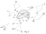
- the opening angle ⁇ between a long tooth profile 18, 19 located in the forceps jaw 17 and the adjacent short tooth profile 20, 21 is 135 ° (FIG. FIG. 3 ).
- the length L of the forceps jaw 17 is 21.4 mm ( FIG. 5 ).
- interlocking interlocking teeth 24 of the splines 22 inside the tips 15, 16 are these tips 15, 16 facing away from inner splines 28, 29 next to the forceps jaw 17 (FIG. FIG. 4 ) extending in a straight line and arranged at a distance from one another and provided with teeth 30 of equal length in longitudinal section 27 having teeth 30 ( FIGS. 4 and 5 ).
- these inner tooth profiles 28, 29 are arranged at an angle ⁇ of 2.4 ° opening away from the tips 15, 16 ( FIG. 3 ).
- the opening angle ⁇ between the sides 27 of two adjacent teeth 24 of the toothed profiles 20, 21, 22, 28 and 29 inside the tips 15, 16, the short inner contours of the forceps jaw 17 and on the side facing away from the tips 15, 16 side of the forceps jaw 17 is 90 °.
Landscapes
- Engineering & Computer Science (AREA)
- Mechanical Engineering (AREA)
- Clamps And Clips (AREA)
- Gripping Jigs, Holding Jigs, And Positioning Jigs (AREA)
- Surgical Instruments (AREA)
- Cutting Tools, Boring Holders, And Turrets (AREA)
Abstract
Description
- Die Erfindung betrifft eine Greifzange mit einem verstellbaren Gelenk gemäß den Merkmalen im Oberbegriff des Patentanspruchs 1.
- Eine solche Greifzange zählt im Umfang der
EP 0 528 252 A1 zum Stand der Technik. Sie weist zwei über ein Gelenk miteinander gekoppelte Zangenarme auf, die jeweils in einen Griffabschnitt, in einen Übergangsabschnitt und in einen Kopfabschnitt mit einer Greifbacke gegliedert sind. Eine zweite Greifbacke ist zum benachbarten Übergangsabschnitt quer abstehend und die andere erste Greifbacke zum angrenzenden Übergangsabschnitt unter einem Winkel von 45° angeordnet. Die Innenkonturen der Greifbacken sind S-förmig gestaltet. Dadurch wird bei sich kontaktierenden Spitzen der Greifbacken von diesen ein parallelogrammförmiges Zangenmaul gebildet. Die langen Innenkonturen des Zangenmauls sind als Verzahnungsprofile mit im Längsschnitt dreieckförmigen Zähnen gestaltet. Auch die neben dem Zangenmaul liegenden Innenkonturen der Greifbacken weisen Verzahnungsprofile mit im Längsschnitt dreieckförmigen Zähnen auf. - Der Erfindung liegt - ausgehend vom Stand der Technik - die Aufgabe zugrunde, die bekannte Greifzange derart weiterzuentwickeln, dass einem Monteur ihre Handhabung auch in schwierigen Montagesituationen sowie bei längerem Einsatz bei verbesserter Anlage an einem Gegenstand wesentlich erleichtert wird.
- Die Lösung dieser Aufgabe besteht nach der Erfindung in den Merkmalen des Patentanspruchs 1.
- Vorteilhafte Weiterbildungen der Erfindung sind Gegenstand der Patentansprüche 2 bis 17.
- Erfindungsgemäß sind nunmehr die langen Innenkonturen des parallelogrammförmigen Zangenmauls durch Verzahnungsprofile mit im Längsschnitt unterschiedlich lange Seiten aufweisenden Zähnen und die kurzen Innenkonturen des Zangenmauls sowie die Innenkonturen der Spitzen der Greifbacken durch Verzahnungsprofile mit im Längsschnitt gleich lange Seiten aufweisenden Zähnen gebildet. Des Weiteren ist es von Bedeutung, dass das in der zweiten Greifbacke angeordnete lange zweite Verzahnungsprofil des Zangenmauls sich linear erstreckt und das in der ersten Greifbacke befindliche lange erste Verzahnungsprofil zum zweiten Verzahnungsprofil hin konvex verläuft.
- Eine derart gestaltete Greifzange hat insbesondere in ihrer Verwendung als Wasserpumpenzange den Vorteil, dass einerseits über die Spitzen der Greifbacken Gegenstände sicher erfasst und gehandhabt werden können, dass andererseits jedoch durch die besondere Gestaltung des parallelogrammförmigen Zangenmauls im Hinblick auf die dort vorgesehenen speziellen Verzahnungsprofile im Querschnitt runde oder mehrkantige Gegenstände, deren Oberflächen gegebenenfalls durch beispielsweise Schmiermittel verunreinigt sind und eine nur geringe Rutschfestigkeit aufweisen, dennoch in allen Einsatzsituationen einwandfrei erfasst und sicher gehandhabt werden können.
- Bei formschlüssig ineinander greifenden Zähnen der Verzahnungsprofile innenseitig der Spitzen sind die langen Seiten der Zähne der langen Verzahnungsprofile in dem Zangenmaul weitgehend parallel zueinander und zu einer die Zähne der Verzahnungsprofile innenseitig der Spitzen schneidenden Mittellängsebene angeordnet.
- Ferner kann in diesem Zusammenhang der mittlere Abstand des langen ersten Verzahnungsprofils des Zangenmauls zum langen zweiten Verzahnungsprofil vorzugsweise 4,5 mm betragen.
- Die Höhe der Zähne des langen zweiten Verzahnungsprofils im Zangenmaul beläuft sich auf 0,52 mm und die Höhe der Zähne des langen ersten Verzahnungsprofils 0,58 mm. Das heißt, die Zähne des konvex verlaufenden Verzahnungsprofils sind höher als die Zähne des sich linear erstreckenden Verzahnungsprofils in dem Zangenmaul ausgebildet.
- Die Erfassung eines Gegenstands durch die Greifzange und ihre sichere Handhabung nach dem Erfassen wird dadurch verbessert, dass der Öffnungswinkel zwischen der kurzen Seite eines Zahns der langen Verzahnungsprofile im Zangenmaul und der langen Seite des jeweils benachbarten Zahns 105° beträgt. Außerdem ist der Öffnungswinkel zwischen der kurzen Seite eines Zahns der langen Verzahnungsprofile im Zangenmaul und der die Zähne der Verzahnungsprofile innenseitig der Spitzen schneidenden Mittellängsebene bei formschlüssig ineinander greifenden Zähnen der Verzahnungsprofile innenseitig der Spitzen vorzugsweise 70° bemessen.
- Es hat sich ferner als vorteilhaft erwiesen, wenn die Höhe der Zähne der kurzen Verzahnungsprofile im Zangenmaul 0,36 mm beträgt.
- Die langen Verzahnungsprofile im Zangenmaul sind zu der die Zähne der Verzahnungsprofile innenseitig der Spitzen schneidenden Mittellängsebene bei formschlüssig ineinander greifenden Zähnen der Verzahnungsprofile der Spitzen bevorzugt unter einem Winkel von 15° angeordnet.
- Der Öffnungswinkel zwischen einem im Zangenmaul vorgesehenen langen Verzahnungsprofil und dem benachbarten kurzen Verzahnungsprofil beträgt 135°.
- Der Öffnungswinkel zwischen zwei gleich lange Seiten aufweisenden Zähnen der Verzahnungsprofile innenseitig der Spitzen, der kurzen Verzahnungsprofile im Zangenmaul sowie der Verzahnungsprofile auf der den Spitzen abgewandten Seite des Zangenmaul beträgt 90°.
- Die Länge des Zangenmauls ist vorzugsweise 21,4 mm bemessen.
- Eine weitere Verbesserung der Handhabung der Greifzange wird dadurch erzielt, dass bei formschlüssig ineinander greifenden Zähnen der Verzahnungsprofile innenseitig der Spitzen diesen Spitzen abgewandte innere Verzahnungsprofile neben dem Zangenmaul sich geradlinig erstrecken, im Abstand zueinander angeordnet und mit im Längsschnitt gleich lange Seiten aufweisenden Zähnen versehen sind. Sinnvoll ist es hierbei außerdem, dass die den Spitzen abgewandten, neben dem Zangenmaul liegenden inneren Verzahnungsprofile unter einem sich von den Spitzen weg öffnenden Winkel von 2,4° zueinander angeordnet sind.
- In dem neben dem Zangenmaul liegenden inneren Verzahnungsprofil der zweiten Greifbacke ist eine halbkreisförmige Mulde ausgebildet. Die Mulde weist einen Radius von 2 mm auf.
- Schließlich ist es bei der erfindungsgemäßen Greifzange noch von Vorteil, dass ein Zangenarm in seinem Übergangsabschnitt einen Längsschlitz aufweist und der andere Zangenarm mit seinem Übergangsabschnitt den Längsschlitz durchgreift sowie ein Langloch mit einem Verzahnungsprofil besitzt, wobei in dem zweiten Zangenarm ein Sperrstück linear verschiebbar gelagert ist, um das der erste Zangenarm drehbar ist. Auf diese Weise können über das Sperrstück diverse Relativstellungen der Zangenarme eingestellt werden, in der beide Zangenarme linear lagefixiert, jedoch drehbar zueinander angeordnet sind.
- Schließlich ist noch zweckmäßig, dass die Zangenarme schmiedetechnisch hergestellt sind. Hierdurch ergeben sich hohe Festigkeitseigenschaften bei gleichzeitigem Gewichtseinsparungspotential. Vorzugsweise sind die Zangenarme aus einem Stahl hergestellt, der eine lange Einsatzzeit der Greifzange gewährleistet.
- Die Erfindung ist nachfolgend anhand eines in den Zeichnungen dargestellten Ausführungsbeispiels näher erläutert. Es zeigen:
- Figur 1
- in der Seitenansicht eine Greifzange;
- Figur 2
- die Greifzange in Richtung des Pfeils II der
Figur 1 gesehen; - Figur 3
- in der Seitenansicht den Greifbereich der Greifzange;
- Figur 4
- ebenfalls in der Seitenansicht einen vergrößerten Teilabschnitt des Greifbereichs der
Figur 3 und - Figur 5
- nochmals den vergrößerten Teilabschnitt des Greifbereichs.
- In den
Figuren 1 und 2 ist mit 1 eine Greifzange in Form einer Wasserpumpenzange bezeichnet. Die Greifzange 1 weist einen ersten Zangenarm 2 und einen zweiten Zangenarm 3 auf, die über ein verstellbares Gelenk 4 miteinander gekoppelt sind. - Jeder Zangenarm 2, 3 ist in einen Griffabschnitt 5, 5a, einen Übergangsabschnitt 6, 6a und in einen Kopfabschnitt 7, 7a mit einer Greifbacke 8, 8a gegliedert.
- Aus der
Figur 2 ist darüber hinaus ersichtlich, dass der erste Zangenarm 2 in seinem Übergangsabschnitt 6 einen Längsschlitz 9 aufweist und der andere Zangenarm 3 mit seinem Übergangsabschnitt 6a den Längsschlitz 9 durchgreift. - Ferner weist die Greifzange 1 eine Verschlussmechanik 10 auf, die es erlaubt, eine translatorische Verstellbewegung des zweiten Zangenarms 3 zum ersten Zangenarm 2 durchzuführen, wodurch sich die Öffnungsweite der Greifzange 1 zwischen den Kopfabschnitten 7, 7a stufenweise einstellen lässt.
- Zur Durchführung der translatorischen Verstellbewegung ist in dem Übergangsabschnitt 6a des zweiten Zangenarms 3 ein Langloch 11 angeordnet, das an seinen inneren Längsrändern jeweils ein sägezahnförmiges Rastprofil 12 aufweist. Des Weiteren ist am ersten Zangenarm 2 ein Betätigungshebel 13 vorgesehen, der bei Betätigung ein Sperrstück 14 in axialer Richtung verschiebt, so dass es von einer Sperrstellung in eine Lösestellung verlagert wird und damit die translatorische Verstellbewegung des ersten Zangenarms 2 relativ zum zweiten Zangenarm 3 ermöglicht. Befindet sich dann das Sperrstück 14 in der neuen Sperrstellung, können die beiden Zangenarme 2, 3 um das Gelenk 4 verschwenkt werden.
- Wie die
Figuren 1 und3 erkennen lassen, ist die zweite Greifbacke 8a des zweiten Zangenarms 3 zum benachbarten Übergangsabschnitt 6a unter einem Winkel α von 90° quer abstehend und die erste Greifbacke 8 am ersten Zangenarm 2 zum angrenzenden Übergangsabschnitt 6 unter einem Winkel β von 45° angeordnet. - Des Weiteren ist insbesondere anhand der
Figuren 4 und 5 zu sehen, dass die einander zugewandten S-förmigen Innenkonturen der Greifbacken 8, 8a unter Ausbildung eines bei sich kontaktierenden Spitzen 15, 16 der Greifbacken 8, 8a parallelogrammförmigen Zangenmauls 17 Verzahnungsprofile 18 bis 22 mit im Längsschnitt dreieckförmigen Zähnen 23, 24 aufweisen. - Die
Figur 4 und 5 zeigen in diesem Zusammenhang ferner, dass die langen Innenkonturen des parallelogrammförmigen Zangenmauls 17 durch Verzahnungsprofile 18, 19 mit im Längsschnitt unterschiedlich lange Seiten 25, 26 aufweisenden Zähnen 23 und die kurzen Innenkonturen im Zangenmaul 17 sowie die Innenkonturen der Spitzen 15, 16 der Greifbacken 8, 8a durch Verzahnungsprofile 20, 21, 22 mit im Längsschnitt gleich lange Seiten 27 aufweisenden Zähnen 24 gebildet sind. Außerdem ist erkennbar, dass das in der zweiten Greifbacke 8a angeordnete lange zweite Verzahnungsprofil 19 im Zangenmaul 17 sich linear erstreckt und das in der ersten Greifbacke 8 befindliche lange erste Verzahnungsprofil 18 zum zweiten Verzahnungsprofil 19 konvex verläuft. Der Radius R des konvexen Verzahnungsprofils 18 beträgt 45 mm. - Bei formschlüssig ineinander greifenden Zähnen 24 der Verzahnungsprofile 22 innenseitig der Spitzen 15, 16 (
Figur 5 ) sind die langen Seiten 25 der Zähne 23 der langen Verzahnungsprofile 18, 19 im Zangenmaul 17 weitgehend parallel zueinander und zu einer die Zähne 24 der Verzahnungsprofile 22 innenseitig der Spitzen 15, 16 schneidenden Mittellängsebene MLE angeordnet. In diesem Fall beträgt der mittlere Abstand A des langen zweiten Verzahnungsprofils 19 im Zangenmaul 17 zum langen ersten Verzahnungsprofil 18 4,5 mm. Die Höhe H der Zähne 23 des langen zweiten Verzahnungsprofils 19 im Zangenmaul 17 ist 0,52 mm und die Höhe H1 der Zähne 23 des langen ersten Verzahnungsprofils 18 ist 0,58 mm bemessen. - Wie die
Figur 3 zeigt, beträgt der Öffnungswinkel γ zwischen der kurzen Seite 26 eines Zahns 23 der langen Verzahnungsprofile 18, 19 im Zangenmaul 17 und der langen Seite 25 des jeweils benachbarten Zahns 23 105°. Hingegen ist der Öffnungswinkel δ zwischen der kurzen Seite 26 eines Zahns 23 der langen Verzahnungsprofile 18, 19 im Zangenmaul 17 und der die Zähne 24 der Verzahnungsprofile 22 innenseitig der Spitzen 15, 16 schneidenden Mittellängsebene MLE 70° bemessen. - Die Höhe H2 der Zähne 24 der Verzahnungsprofile 20, 21 der kurzen Innenkonturen im Zangenmaul 17 beträgt 0,36 mm (
Figur 5 ). - Die langen Verzahnungsprofile 18, 19 im Zangenmaul 17 sind zu der die Zähne 24 der Verzahnungsprofile 22 innenseitig der Spitzen 15, 16 schneidenden Mittellängsebene MLE bei formschlüssig ineinander greifenden Zähnen 24 der Verzahnungsprofile 22 der Spitzen 15,16 unter einem Winkel ε von 15° angeordnet. Der Öffnungswinkel ζ zwischen einem im Zangenmaul 17 befindlichen langen Verzahnungsprofil 18, 19 und dem benachbarten kurzen Verzahnungsprofil 20, 21 beträgt 135° (
Figur 3 ). - Die Länge L des Zangenmauls 17 beträgt 21,4 mm (
Figur 5 ). - Bei formschlüssig ineinander greifenden Zähnen 24 der Verzahnungsprofile 22 innenseitig der Spitzen 15, 16 sind diesen Spitzen 15, 16 abgewandte innere Verzahnungsprofile 28, 29 neben dem Zangenmaul 17 (
Figur 4 ) sich geradlinig erstreckend und im Abstand zueinander angeordnet sowie mit im Längsschnitt gleich lange Seiten 27 aufweisenden Zähnen 30 versehen (Figuren 4 und 5 ). Außerdem ist erkennbar, dass diese inneren Verzahnungsprofile 28, 29 unter einem sich von den Spitzen 15, 16 weg öffnenden Winkel η von 2,4° angeordnet sind (Figur 3 ). - In dem neben dem Zangenmaul 17 liegenden inneren Verzahnungsprofil 28 der zweiten Greifbacke 8a ist eine halbkreisförmige Mulde 31 ausgebildet. Diese weist einen Radius R1 von 2 mm auf (
Figuren 4 und 5 ). - Der Öffnungswinkel θ zwischen den Seiten 27 zweier benachbarter Zähne 24 der Verzahnungsprofile 20, 21, 22, 28 und 29 innenseitig der Spitzen 15, 16, der kurzen Innenkonturen des Zangenmauls 17 sowie auf der den Spitzen 15, 16 abgewandten Seite des Zangenmauls 17 beträgt 90°.
-
- 1
- - Greifzange
- 2
- - erster Zangenarm
- 3
- - zweiter Zangenarm
- 4
- - Gelenk
- 5
- - Griffabschnitt v. 2
- 5a
- - Griffabschnitt v. 3
- 6
- - Übergangsabschnitt v. 2
- 6a
- - Übergangsabschnitt v. 3
- 7
- - Kopfabschnitt v. 2
- 7a
- - Kopfabschnitt v, 3
- 8
- - erste Greifbacke v. 2
- 8a
- - zweite Greifbacke v. 3
- 9
- - Längsschlitz in 6
- 10
- - Verschlussmechanik
- 11
- - Langloch in 6a
- 12
- - Rastprofile in 11
- 13
- - Betätigungshebel
- 14
- - Sperrstück
- 15
- - Spitze v. 8
- 16
- - Spitze v. 8a
- 17
- - Zangenmaul
- 18
- - langes Verzahnungsprofil an 8
- 19
- - langes Verzahnungsprofil an 8a
- 20
- - kurzes Verzahnungsprofil an 8
- 21
- - kurzes Verzahnungsprofil an 8a
- 22
- - Verzahnungsprofile an 15 u. 16
- 23
- - Zähne v. 18 u. 19
- 24
- - Zähne v. 20,21,22
- 25
- - lange Seiten v. 23
- 26
- - kurze Seiten v. 23
- 27
- - Seiten v. 24
- 28
- - Verzahnungsprofil neben 17
- 29
- - Verzahnungsprofil neben 17
- 30
- - Zähne v. 28, 29
- 31
- - Mulde in 28
- A
- - Abstand zw. 18 u. 19
- H
- - Höhe v. 23 in 19
- H1
- - Höhe v. 23 in 18
- H2
- - Höhe v. 24
- L
- - Länge v. 17
- R
- - Radius v. 18
- R1
- - Radius v. 31
- MLE
- - Mittellängsebene zw. 24 v. 15 u. 16
- α
- - Winkel zw. 6a u. 8a
- β
- - Winkel zw. 6 u. 8
- γ
- - Winkel zw. 25 u. 26
- δ
- - Winkel zw. 26 u. MLE
- ε
- - Winkel zw. 18, 19 u. MLE
- ζ
- - Winkel zw. 18,19 u. 20,21
- η
- - Winkel zw. 28 u. 29
- θ
- - Winkel zw. 27
Claims (17)
- Greifzange (1) mit einem verstellbaren Gelenk (4), welche zwei über das Gelenk (4) miteinander gekoppelte Zangenarme (2, 3) aufweist, die jeweils in einen Griffabschnitt (5, 5a), einen Übergangsabschnitt (6, 6a) und in einen Kopfabschnitt (7, 7a) mit einer Greifbacke (8, 8a) gegliedert sind, wobei eine zweite Greifbacke (8a) zum benachbarten Übergangsabschnitt (6a) quer abstehend und die andere erste Greifbacke (8) zum angrenzenden Übergangsabschnitt (6) unter einem Winkel (β) zwischen etwa 35° und 55° angeordnet ist, und wobei die einander zugewandten S-förmigen Innenkonturen der Greifbacken (8, 8a) unter Ausbildung eines bei sich kontaktierenden Spitzen (15, 16) der Greifbacken (8, 8a) parallelogrammförmigen Zangenmauls (17) Verzahnungsprofile (18, 19, 20, 21) mit im Längsschnitt dreieckförmigen Zähnen (23, 24) aufweisen, dadurch gekennzeichnet, dass die langen Innenkonturen des parallelogrammförmigen Zangenmauls (17) durch Verzahnungsprofile (18, 19) mit im Längsschnitt unterschiedlich lange Seiten (25, 26) aufweisenden Zähnen (23) und die kurzen Innenkonturen des Zangenmauls (17) sowie die Innenkonturen der Spitzen (15, 16) der Greifbacken (8, 8a) durch Verzahnungsprofile (20, 21, 22) mit im Längsschnitt gleich lange Seiten (27) aufweisenden Zähnen (24) gebildet sind, wobei das in der zweiten Greifbacke (8a) angeordnete lange zweite Verzahnungsprofil (19) des Zangenmauls (17) sich linear erstreckt und das in der ersten Greifbacke (8) befindliche lange erste Verzahnungsprofil (18) zum zweiten Verzahnungsprofil (19) hin konvex verläuft.
- Greifzange nach Anspruch 1, dadurch gekennzeichnet, dass bei formschlüssig ineinander greifenden Zähnen (24) der Verzahnungsprofile (22) innenseitig der Spitzen (15, 16) die langen Seiten (25) der Zähne (23) der langen Verzahnungsprofile (18, 19) im Zangenmaul (17) weitgehend parallel zueinander und zu einer die Zähne (24) der Verzahnungsprofile (22) innenseitig der Spitzen (15, 16) schneidenden Mittellängsebene (MLE) angeordnet sind.
- Greifzange nach Anspruch 1 oder 2, dadurch gekennzeichnet, dass bei formschlüssig ineinander greifenden Zähnen (24) der Verzahnungsprofile (22) innenseitig der Spitzen (15, 16) der mittlere Abstand (A) des langen zweiten Verzahnungsprofils (19) im Zangenmaul (17) zum langen ersten Verzahnungsprofil (18) 4,5 mm beträgt.
- Greifzange nach einem der Ansprüche 1 bis 3, dadurch gekennzeichnet, dass die Höhe (H) der Zähne (23) des langen zweiten Verzahnungsprofils (19) im Zangenmaul (17) 0,52 mm und die Höhe (H1) der Zähne (23) des langen ersten Verzahnungsprofils (18) 0,58 mm beträgt.
- Greifzange nach einem der Ansprüche 1 bis 4, dadurch gekennzeichnet, dass der Öffnungswinkel (γ) zwischen der kurzen Seite (26) eines Zahns (23) der langen Verzahnungsprofile (18, 19) im Zangenmaul (17) und der langen Seite (25) des jeweils benachbarten Zahns (23) 105° beträgt.
- Greifzange nach einem der Ansprüche 1 bis 5, dadurch gekennzeichnet, dass der Öffnungswinkel (δ) zwischen der kurzen Seite (26) eines Zahns (23) der langen Verzahnungsprofile (18, 19) im Zangenmaul (17) und der die Zähne (24) der Verzahnungsprofile (22) innenseitig der Spitzen (15, 16) schneidenden Mittellängsebene (MLE) bei formschlüssig ineinander greifenden Zähnen (24) der Verzahnungsprofile (22) innenseitig der Spitzen (15, 16) 70° beträgt.
- Greifzange nach einem der Ansprüche 1 bis 6, dadurch gekennzeichnet, dass die Höhe (H2) der Zähne (24) der Verzahnungs-profile (20, 21) der kurzen Innenkonturen im Zangenmaul (17) 0,36 mm beträgt.
- Greifzange nach einem der Ansprüche 1 bis 7, dadurch gekennzeichnet, dass die langen Verzahnungsprofile (18, 19) im Zangenmaul (17) zu der die Zähne (24) der Verzahnungsprofile (22) innenseitig der Spitzen (15, 16) schneidenden Mittellängsebene (MLE) bei formschlüssig ineinander greifenden Zähnen (24) der Verzahnungsprofile (22) der Spitzen (15, 16) unter einem Winkel (ε) von 15° angeordnet sind.
- Greifzange nach einem der Ansprüche 1 bis 8, dadurch gekennzeichnet, dass der Öffnungswinkel (ζ) zwischen einem im Zangenmaul (17) befindlichen langen Verzahnungsprofil (18, 19) und dem benachbarten kurzen Verzahnungsprofil (20, 21) 135° beträgt.
- Greifzange nach einem der Ansprüche 1 bis 9, dadurch gekennzeichnet, dass der Öffnungswinkel (θ) zwischen zwei gleich lange Seiten (27) aufweisenden Zähnen (24) der Verzahnungsprofile (22) innenseitig der Spitzen (15, 16), der kurzen Verzahnungsprofile (20, 21) im Zangenmaul (17) sowie der Verzahnungsprofile (28, 29) auf der den Spitzen (15, 16) abgewandten Seite des Zangenmauls (17) 90° beträgt.
- Greifzange nach einem der Ansprüche 1 bis 10, dadurch gekennzeichnet, dass die Länge (L) des Zangenmauls (17) 21,4 mm beträgt.
- Greifzange nach einem der Ansprüche 1 bis 11, dadurch gekennzeichnet, dass bei formschlüssig ineinander greifenden Zähnen (24) der Verzahnungsprofile (22) innenseitig der Spitzen (15, 16) diesen Spitzen (15, 16) abgewandte innere Verzahnungsprofile (28, 29) neben dem Zangenmaul (17) sich geradlinig erstrecken, im Abstand zueinander angeordnet und mit im Längsschnitt gleich lange Seiten (27) aufweisenden Zähnen (30) versehen sind.
- Greifzange nach Anspruch 12, dadurch gekennzeichnet, dass die den Spitzen (15, 16) abgewandten, neben dem Zangenmaul (17) liegenden inneren Verzahnungsprofile (28, 29) unter einem sich von den Spitzen (15, 16) weg öffnenden Winkel (η) von 2,4° zueinander angeordnet sind.
- Greifzange nach Anspruch 12 oder 13, dadurch gekennzeichnet, dass in dem neben dem Zangenmaul (17) liegenden inneren Verzahnungsprofil (28) der zweiten Greifbacke (8a) eine halbkreisförmige Mulde (31) ausgebildet ist.
- Greifzange nach Anspruch 14, dadurch gekennzeichnet, dass die Mulde (31) einen Radius (R1) von 2 mm aufweist.
- Greifzange nach einem der Ansprüche 1 bis 15, dadurch gekennzeichnet, dass ein Zangenarm (2) in seinem Übergangsabschnitt (6) einen Längsschlitz (9) aufweist und der andere Zangenarm (3) mit seinem Übergangsabschnitt (6a) den Längsschlitz (9) durchgreift sowie ein Langloch (11) mit zwei einander gegenüber liegenden Rastprofilen (12) besitzt, wobei in dem zweiten Zangenarm (3) ein Sperrstück (14) linear verschiebbar gelagert ist, um welches der erste Zangenarm (2) drehbar ist.
- Greifzange nach einem der Ansprüche 1 bis 16, dadurch gekennzeichnet, dass die Zangenarme (2, 3) schmiedetechnisch hergestellt sind.
Applications Claiming Priority (1)
| Application Number | Priority Date | Filing Date | Title |
|---|---|---|---|
| DE202013101985U DE202013101985U1 (de) | 2013-05-07 | 2013-05-07 | Greifzange |
Publications (2)
| Publication Number | Publication Date |
|---|---|
| EP2801444A1 true EP2801444A1 (de) | 2014-11-12 |
| EP2801444B1 EP2801444B1 (de) | 2019-12-25 |
Family
ID=48652958
Family Applications (1)
| Application Number | Title | Priority Date | Filing Date |
|---|---|---|---|
| EP14165070.5A Active EP2801444B1 (de) | 2013-05-07 | 2014-04-17 | Greifzange |
Country Status (5)
| Country | Link |
|---|---|
| EP (1) | EP2801444B1 (de) |
| CN (1) | CN104139347B (de) |
| DE (1) | DE202013101985U1 (de) |
| ES (1) | ES2775205T3 (de) |
| TW (1) | TWI546165B (de) |
Cited By (4)
| Publication number | Priority date | Publication date | Assignee | Title |
|---|---|---|---|---|
| CN104985089A (zh) * | 2015-07-22 | 2015-10-21 | 刘剑 | 一种线缆弯线钳 |
| USD910395S1 (en) | 2019-03-11 | 2021-02-16 | Milwaukee Electric Tool Corporation | Pliers |
| US11247308B2 (en) | 2017-09-11 | 2022-02-15 | Milwaukee Electric Tool Corporation | Locking pliers with movable torque-increasing jaw section |
| US11541514B2 (en) | 2016-03-23 | 2023-01-03 | Milwaukee Electric Tool Corporation | Locking pliers |
Families Citing this family (3)
| Publication number | Priority date | Publication date | Assignee | Title |
|---|---|---|---|---|
| JP6236179B1 (ja) * | 2017-03-07 | 2017-11-22 | 株式会社エンジニア | ウォーターポンププライヤ、およびカバー部材 |
| DE102021113461A1 (de) | 2021-04-07 | 2022-10-13 | Knipex-Werk C. Gustav Putsch Kg | Zange |
| TW202245992A (zh) | 2021-04-07 | 2022-12-01 | 德商C 格斯塔夫 布希 克尼佩克斯工廠 | 鉗子 |
Citations (3)
| Publication number | Priority date | Publication date | Assignee | Title |
|---|---|---|---|---|
| FR2642351A1 (fr) * | 1989-01-27 | 1990-08-03 | Super Ego Tools | Pince perfectionnee |
| EP0528252A1 (de) | 1991-08-08 | 1993-02-24 | Knipex-Werk C. Gustav Putsch | Zange mit zwei Zangenschenkeln |
| DE29703681U1 (de) * | 1997-02-28 | 1997-06-19 | Will Werkzeugfabrik Gmbh Co Kg | Greifzange |
Family Cites Families (5)
| Publication number | Priority date | Publication date | Assignee | Title |
|---|---|---|---|---|
| GB191000144A (en) * | 1910-01-03 | 1910-11-17 | Wilhelm Kessing | An Improved Pipe Wrench or Spanner. |
| GB1370605A (en) * | 1973-02-23 | 1974-10-16 | Putsch K | Pipe wrench |
| DE3460942D1 (en) * | 1983-02-02 | 1986-11-20 | Putsch Gustav Knipex Werk | Gripping plyers |
| DE10343412A1 (de) * | 2003-05-22 | 2004-12-09 | Knipex-Werk C. Gustav Putsch Kg | Einhandbetätigbare Zange |
| CN201086256Y (zh) * | 2007-08-30 | 2008-07-16 | 文登威力高档工具有限公司 | 一种自调水泵钳 |
-
2013
- 2013-05-07 DE DE202013101985U patent/DE202013101985U1/de not_active Expired - Lifetime
-
2014
- 2014-04-04 CN CN201410133685.7A patent/CN104139347B/zh active Active
- 2014-04-17 EP EP14165070.5A patent/EP2801444B1/de active Active
- 2014-04-17 ES ES14165070T patent/ES2775205T3/es active Active
- 2014-04-30 TW TW103115646A patent/TWI546165B/zh active
Patent Citations (3)
| Publication number | Priority date | Publication date | Assignee | Title |
|---|---|---|---|---|
| FR2642351A1 (fr) * | 1989-01-27 | 1990-08-03 | Super Ego Tools | Pince perfectionnee |
| EP0528252A1 (de) | 1991-08-08 | 1993-02-24 | Knipex-Werk C. Gustav Putsch | Zange mit zwei Zangenschenkeln |
| DE29703681U1 (de) * | 1997-02-28 | 1997-06-19 | Will Werkzeugfabrik Gmbh Co Kg | Greifzange |
Cited By (6)
| Publication number | Priority date | Publication date | Assignee | Title |
|---|---|---|---|---|
| CN104985089A (zh) * | 2015-07-22 | 2015-10-21 | 刘剑 | 一种线缆弯线钳 |
| US11541514B2 (en) | 2016-03-23 | 2023-01-03 | Milwaukee Electric Tool Corporation | Locking pliers |
| US11247308B2 (en) | 2017-09-11 | 2022-02-15 | Milwaukee Electric Tool Corporation | Locking pliers with movable torque-increasing jaw section |
| US11850707B2 (en) | 2017-09-11 | 2023-12-26 | Milwaukee Electric Tool Corporation | Locking pliers with movable torque-increasing jaw section |
| USD910395S1 (en) | 2019-03-11 | 2021-02-16 | Milwaukee Electric Tool Corporation | Pliers |
| USD951731S1 (en) | 2019-03-11 | 2022-05-17 | Milwaukee Electric Tool Corporation | Pliers |
Also Published As
| Publication number | Publication date |
|---|---|
| TWI546165B (zh) | 2016-08-21 |
| EP2801444B1 (de) | 2019-12-25 |
| CN104139347B (zh) | 2016-09-07 |
| CN104139347A (zh) | 2014-11-12 |
| TW201505787A (zh) | 2015-02-16 |
| DE202013101985U1 (de) | 2013-05-17 |
| ES2775205T3 (es) | 2020-07-24 |
Similar Documents
| Publication | Publication Date | Title |
|---|---|---|
| EP2801444B1 (de) | Greifzange | |
| EP0421107B1 (de) | Schlüsselzange | |
| EP2773490B1 (de) | Zange | |
| DE102009050865B3 (de) | Montagezange mit lösbarer Gegenklinke | |
| WO2019105703A1 (de) | Pressbacken, sowie presszange mit zwei zangenbacken | |
| EP2709804B1 (de) | Zange | |
| EP2636489B1 (de) | Wasserpumpenzange mit Betätigungshebel | |
| EP3313619B1 (de) | Zange mit zwei sich in einem gelenkbolzen kreuzenden zangenschenkeln | |
| EP3563973B1 (de) | Zange | |
| EP3784439B1 (de) | Zange | |
| WO2018115171A2 (de) | Handwerkzeug mit einer ratschenfunktion | |
| DE102009059053A1 (de) | Presswerkzeug zum Radialverpressen von Werkstücken sowie Werkzeug mit wenigstens zwei relativ zueinander bewegbaren Werkzeugteilen | |
| DE19933033B4 (de) | Klemm- oder Spreizzange | |
| DE102014111620B4 (de) | Spannschlüssel | |
| DE10044874A1 (de) | Schlüsselzange | |
| DE8314686U1 (de) | Greifzange mit Rillengleitgelenk | |
| DE19740498A1 (de) | Werkzeuggreifer für einen Speicherplatz eines Kettenmagazines an einer Werkzeugmaschine | |
| DE102021113461A1 (de) | Zange | |
| DE69934300T2 (de) | Selbsteinstellende Zange | |
| DE19910838A1 (de) | Zange zum Verpressen von Hülsenverbindern | |
| EP4319942A1 (de) | Zange | |
| DE202024101563U1 (de) | Zange | |
| DE1481800C (de) | Hebeklaue | |
| DE202011000858U1 (de) | Kardangelenk | |
| DE202004015720U1 (de) | Mit Hilfe eines Rastglieds verstellbare Greifzange |
Legal Events
| Date | Code | Title | Description |
|---|---|---|---|
| PUAI | Public reference made under article 153(3) epc to a published international application that has entered the european phase |
Free format text: ORIGINAL CODE: 0009012 |
|
| 17P | Request for examination filed |
Effective date: 20140903 |
|
| AK | Designated contracting states |
Kind code of ref document: A1 Designated state(s): AL AT BE BG CH CY CZ DE DK EE ES FI FR GB GR HR HU IE IS IT LI LT LU LV MC MK MT NL NO PL PT RO RS SE SI SK SM TR |
|
| AX | Request for extension of the european patent |
Extension state: BA ME |
|
| 17Q | First examination report despatched |
Effective date: 20151014 |
|
| GRAP | Despatch of communication of intention to grant a patent |
Free format text: ORIGINAL CODE: EPIDOSNIGR1 |
|
| STAA | Information on the status of an ep patent application or granted ep patent |
Free format text: STATUS: GRANT OF PATENT IS INTENDED |
|
| INTG | Intention to grant announced |
Effective date: 20190920 |
|
| GRAS | Grant fee paid |
Free format text: ORIGINAL CODE: EPIDOSNIGR3 |
|
| GRAA | (expected) grant |
Free format text: ORIGINAL CODE: 0009210 |
|
| STAA | Information on the status of an ep patent application or granted ep patent |
Free format text: STATUS: THE PATENT HAS BEEN GRANTED |
|
| AK | Designated contracting states |
Kind code of ref document: B1 Designated state(s): AL AT BE BG CH CY CZ DE DK EE ES FI FR GB GR HR HU IE IS IT LI LT LU LV MC MK MT NL NO PL PT RO RS SE SI SK SM TR |
|
| REG | Reference to a national code |
Ref country code: GB Ref legal event code: FG4D Free format text: NOT ENGLISH |
|
| REG | Reference to a national code |
Ref country code: CH Ref legal event code: EP |
|
| REG | Reference to a national code |
Ref country code: DE Ref legal event code: R096 Ref document number: 502014013315 Country of ref document: DE |
|
| REG | Reference to a national code |
Ref country code: AT Ref legal event code: REF Ref document number: 1216642 Country of ref document: AT Kind code of ref document: T Effective date: 20200115 |
|
| REG | Reference to a national code |
Ref country code: IE Ref legal event code: FG4D Free format text: LANGUAGE OF EP DOCUMENT: GERMAN |
|
| REG | Reference to a national code |
Ref country code: NL Ref legal event code: FP |
|
| PG25 | Lapsed in a contracting state [announced via postgrant information from national office to epo] |
Ref country code: LT Free format text: LAPSE BECAUSE OF FAILURE TO SUBMIT A TRANSLATION OF THE DESCRIPTION OR TO PAY THE FEE WITHIN THE PRESCRIBED TIME-LIMIT Effective date: 20191225 Ref country code: NO Free format text: LAPSE BECAUSE OF FAILURE TO SUBMIT A TRANSLATION OF THE DESCRIPTION OR TO PAY THE FEE WITHIN THE PRESCRIBED TIME-LIMIT Effective date: 20200325 Ref country code: GR Free format text: LAPSE BECAUSE OF FAILURE TO SUBMIT A TRANSLATION OF THE DESCRIPTION OR TO PAY THE FEE WITHIN THE PRESCRIBED TIME-LIMIT Effective date: 20200326 Ref country code: BG Free format text: LAPSE BECAUSE OF FAILURE TO SUBMIT A TRANSLATION OF THE DESCRIPTION OR TO PAY THE FEE WITHIN THE PRESCRIBED TIME-LIMIT Effective date: 20200325 Ref country code: FI Free format text: LAPSE BECAUSE OF FAILURE TO SUBMIT A TRANSLATION OF THE DESCRIPTION OR TO PAY THE FEE WITHIN THE PRESCRIBED TIME-LIMIT Effective date: 20191225 Ref country code: SE Free format text: LAPSE BECAUSE OF FAILURE TO SUBMIT A TRANSLATION OF THE DESCRIPTION OR TO PAY THE FEE WITHIN THE PRESCRIBED TIME-LIMIT Effective date: 20191225 Ref country code: LV Free format text: LAPSE BECAUSE OF FAILURE TO SUBMIT A TRANSLATION OF THE DESCRIPTION OR TO PAY THE FEE WITHIN THE PRESCRIBED TIME-LIMIT Effective date: 20191225 |
|
| REG | Reference to a national code |
Ref country code: LT Ref legal event code: MG4D |
|
| PG25 | Lapsed in a contracting state [announced via postgrant information from national office to epo] |
Ref country code: RS Free format text: LAPSE BECAUSE OF FAILURE TO SUBMIT A TRANSLATION OF THE DESCRIPTION OR TO PAY THE FEE WITHIN THE PRESCRIBED TIME-LIMIT Effective date: 20191225 Ref country code: HR Free format text: LAPSE BECAUSE OF FAILURE TO SUBMIT A TRANSLATION OF THE DESCRIPTION OR TO PAY THE FEE WITHIN THE PRESCRIBED TIME-LIMIT Effective date: 20191225 |
|
| PG25 | Lapsed in a contracting state [announced via postgrant information from national office to epo] |
Ref country code: AL Free format text: LAPSE BECAUSE OF FAILURE TO SUBMIT A TRANSLATION OF THE DESCRIPTION OR TO PAY THE FEE WITHIN THE PRESCRIBED TIME-LIMIT Effective date: 20191225 |
|
| REG | Reference to a national code |
Ref country code: ES Ref legal event code: FG2A Ref document number: 2775205 Country of ref document: ES Kind code of ref document: T3 Effective date: 20200724 |
|
| PG25 | Lapsed in a contracting state [announced via postgrant information from national office to epo] |
Ref country code: PT Free format text: LAPSE BECAUSE OF FAILURE TO SUBMIT A TRANSLATION OF THE DESCRIPTION OR TO PAY THE FEE WITHIN THE PRESCRIBED TIME-LIMIT Effective date: 20200520 Ref country code: RO Free format text: LAPSE BECAUSE OF FAILURE TO SUBMIT A TRANSLATION OF THE DESCRIPTION OR TO PAY THE FEE WITHIN THE PRESCRIBED TIME-LIMIT Effective date: 20191225 Ref country code: EE Free format text: LAPSE BECAUSE OF FAILURE TO SUBMIT A TRANSLATION OF THE DESCRIPTION OR TO PAY THE FEE WITHIN THE PRESCRIBED TIME-LIMIT Effective date: 20191225 Ref country code: CZ Free format text: LAPSE BECAUSE OF FAILURE TO SUBMIT A TRANSLATION OF THE DESCRIPTION OR TO PAY THE FEE WITHIN THE PRESCRIBED TIME-LIMIT Effective date: 20191225 |
|
| PGFP | Annual fee paid to national office [announced via postgrant information from national office to epo] |
Ref country code: NL Payment date: 20200427 Year of fee payment: 7 Ref country code: ES Payment date: 20200629 Year of fee payment: 7 |
|
| PG25 | Lapsed in a contracting state [announced via postgrant information from national office to epo] |
Ref country code: SK Free format text: LAPSE BECAUSE OF FAILURE TO SUBMIT A TRANSLATION OF THE DESCRIPTION OR TO PAY THE FEE WITHIN THE PRESCRIBED TIME-LIMIT Effective date: 20191225 Ref country code: IS Free format text: LAPSE BECAUSE OF FAILURE TO SUBMIT A TRANSLATION OF THE DESCRIPTION OR TO PAY THE FEE WITHIN THE PRESCRIBED TIME-LIMIT Effective date: 20200425 Ref country code: SM Free format text: LAPSE BECAUSE OF FAILURE TO SUBMIT A TRANSLATION OF THE DESCRIPTION OR TO PAY THE FEE WITHIN THE PRESCRIBED TIME-LIMIT Effective date: 20191225 |
|
| PGFP | Annual fee paid to national office [announced via postgrant information from national office to epo] |
Ref country code: BE Payment date: 20200427 Year of fee payment: 7 Ref country code: GB Payment date: 20200427 Year of fee payment: 7 |
|
| REG | Reference to a national code |
Ref country code: DE Ref legal event code: R097 Ref document number: 502014013315 Country of ref document: DE |
|
| PG25 | Lapsed in a contracting state [announced via postgrant information from national office to epo] |
Ref country code: DK Free format text: LAPSE BECAUSE OF FAILURE TO SUBMIT A TRANSLATION OF THE DESCRIPTION OR TO PAY THE FEE WITHIN THE PRESCRIBED TIME-LIMIT Effective date: 20191225 |
|
| PLBE | No opposition filed within time limit |
Free format text: ORIGINAL CODE: 0009261 |
|
| STAA | Information on the status of an ep patent application or granted ep patent |
Free format text: STATUS: NO OPPOSITION FILED WITHIN TIME LIMIT |
|
| PG25 | Lapsed in a contracting state [announced via postgrant information from national office to epo] |
Ref country code: MC Free format text: LAPSE BECAUSE OF FAILURE TO SUBMIT A TRANSLATION OF THE DESCRIPTION OR TO PAY THE FEE WITHIN THE PRESCRIBED TIME-LIMIT Effective date: 20191225 Ref country code: SI Free format text: LAPSE BECAUSE OF FAILURE TO SUBMIT A TRANSLATION OF THE DESCRIPTION OR TO PAY THE FEE WITHIN THE PRESCRIBED TIME-LIMIT Effective date: 20191225 |
|
| REG | Reference to a national code |
Ref country code: CH Ref legal event code: PL |
|
| 26N | No opposition filed |
Effective date: 20200928 |
|
| PG25 | Lapsed in a contracting state [announced via postgrant information from national office to epo] |
Ref country code: LU Free format text: LAPSE BECAUSE OF NON-PAYMENT OF DUE FEES Effective date: 20200417 Ref country code: LI Free format text: LAPSE BECAUSE OF NON-PAYMENT OF DUE FEES Effective date: 20200430 Ref country code: CH Free format text: LAPSE BECAUSE OF NON-PAYMENT OF DUE FEES Effective date: 20200430 |
|
| PG25 | Lapsed in a contracting state [announced via postgrant information from national office to epo] |
Ref country code: PL Free format text: LAPSE BECAUSE OF FAILURE TO SUBMIT A TRANSLATION OF THE DESCRIPTION OR TO PAY THE FEE WITHIN THE PRESCRIBED TIME-LIMIT Effective date: 20191225 |
|
| PG25 | Lapsed in a contracting state [announced via postgrant information from national office to epo] |
Ref country code: IE Free format text: LAPSE BECAUSE OF NON-PAYMENT OF DUE FEES Effective date: 20200417 |
|
| REG | Reference to a national code |
Ref country code: AT Ref legal event code: MM01 Ref document number: 1216642 Country of ref document: AT Kind code of ref document: T Effective date: 20200417 |
|
| PG25 | Lapsed in a contracting state [announced via postgrant information from national office to epo] |
Ref country code: AT Free format text: LAPSE BECAUSE OF NON-PAYMENT OF DUE FEES Effective date: 20200417 |
|
| REG | Reference to a national code |
Ref country code: NL Ref legal event code: MM Effective date: 20210501 |
|
| GBPC | Gb: european patent ceased through non-payment of renewal fee |
Effective date: 20210417 |
|
| REG | Reference to a national code |
Ref country code: BE Ref legal event code: MM Effective date: 20210430 |
|
| PG25 | Lapsed in a contracting state [announced via postgrant information from national office to epo] |
Ref country code: GB Free format text: LAPSE BECAUSE OF NON-PAYMENT OF DUE FEES Effective date: 20210417 |
|
| PG25 | Lapsed in a contracting state [announced via postgrant information from national office to epo] |
Ref country code: NL Free format text: LAPSE BECAUSE OF NON-PAYMENT OF DUE FEES Effective date: 20210501 |
|
| PG25 | Lapsed in a contracting state [announced via postgrant information from national office to epo] |
Ref country code: TR Free format text: LAPSE BECAUSE OF FAILURE TO SUBMIT A TRANSLATION OF THE DESCRIPTION OR TO PAY THE FEE WITHIN THE PRESCRIBED TIME-LIMIT Effective date: 20191225 Ref country code: MT Free format text: LAPSE BECAUSE OF FAILURE TO SUBMIT A TRANSLATION OF THE DESCRIPTION OR TO PAY THE FEE WITHIN THE PRESCRIBED TIME-LIMIT Effective date: 20191225 Ref country code: CY Free format text: LAPSE BECAUSE OF FAILURE TO SUBMIT A TRANSLATION OF THE DESCRIPTION OR TO PAY THE FEE WITHIN THE PRESCRIBED TIME-LIMIT Effective date: 20191225 |
|
| PG25 | Lapsed in a contracting state [announced via postgrant information from national office to epo] |
Ref country code: MK Free format text: LAPSE BECAUSE OF FAILURE TO SUBMIT A TRANSLATION OF THE DESCRIPTION OR TO PAY THE FEE WITHIN THE PRESCRIBED TIME-LIMIT Effective date: 20191225 |
|
| REG | Reference to a national code |
Ref country code: ES Ref legal event code: FD2A Effective date: 20220706 |
|
| PG25 | Lapsed in a contracting state [announced via postgrant information from national office to epo] |
Ref country code: ES Free format text: LAPSE BECAUSE OF NON-PAYMENT OF DUE FEES Effective date: 20210418 Ref country code: BE Free format text: LAPSE BECAUSE OF NON-PAYMENT OF DUE FEES Effective date: 20210430 |
|
| PGFP | Annual fee paid to national office [announced via postgrant information from national office to epo] |
Ref country code: IT Payment date: 20230426 Year of fee payment: 10 Ref country code: FR Payment date: 20230424 Year of fee payment: 10 Ref country code: DE Payment date: 20230427 Year of fee payment: 10 |