EP2790272A2 - Anordnung zur Stromverteilung sowie deren Kontaktierung und Absicherung der abgehenden Leitungen - Google Patents
Anordnung zur Stromverteilung sowie deren Kontaktierung und Absicherung der abgehenden Leitungen Download PDFInfo
- Publication number
- EP2790272A2 EP2790272A2 EP20140176369 EP14176369A EP2790272A2 EP 2790272 A2 EP2790272 A2 EP 2790272A2 EP 20140176369 EP20140176369 EP 20140176369 EP 14176369 A EP14176369 A EP 14176369A EP 2790272 A2 EP2790272 A2 EP 2790272A2
- Authority
- EP
- European Patent Office
- Prior art keywords
- potential distribution
- busbar
- distribution system
- intermediate element
- rail
- Prior art date
- Legal status (The legal status is an assumption and is not a legal conclusion. Google has not performed a legal analysis and makes no representation as to the accuracy of the status listed.)
- Granted
Links
- 238000009826 distribution Methods 0.000 title claims abstract description 24
- 238000009795 derivation Methods 0.000 abstract description 3
- 239000004033 plastic Substances 0.000 description 4
- 239000004020 conductor Substances 0.000 description 2
- 229910052736 halogen Inorganic materials 0.000 description 2
- 150000002367 halogens Chemical class 0.000 description 2
- 238000003466 welding Methods 0.000 description 2
- 150000001875 compounds Chemical class 0.000 description 1
- 238000004519 manufacturing process Methods 0.000 description 1
- 239000002991 molded plastic Substances 0.000 description 1
- 238000000465 moulding Methods 0.000 description 1
- 230000001681 protective effect Effects 0.000 description 1
- 238000009420 retrofitting Methods 0.000 description 1
- 238000005476 soldering Methods 0.000 description 1
- 229920003002 synthetic resin Polymers 0.000 description 1
- 239000000057 synthetic resin Substances 0.000 description 1
Images


Classifications
-
- H—ELECTRICITY
- H01—ELECTRIC ELEMENTS
- H01R—ELECTRICALLY-CONDUCTIVE CONNECTIONS; STRUCTURAL ASSOCIATIONS OF A PLURALITY OF MUTUALLY-INSULATED ELECTRICAL CONNECTING ELEMENTS; COUPLING DEVICES; CURRENT COLLECTORS
- H01R31/00—Coupling parts supported only by co-operation with counterpart
- H01R31/02—Intermediate parts for distributing energy to two or more circuits in parallel, e.g. splitter
-
- H—ELECTRICITY
- H01—ELECTRIC ELEMENTS
- H01R—ELECTRICALLY-CONDUCTIVE CONNECTIONS; STRUCTURAL ASSOCIATIONS OF A PLURALITY OF MUTUALLY-INSULATED ELECTRICAL CONNECTING ELEMENTS; COUPLING DEVICES; CURRENT COLLECTORS
- H01R9/00—Structural associations of a plurality of mutually-insulated electrical connecting elements, e.g. terminal strips or terminal blocks; Terminals or binding posts mounted upon a base or in a case; Bases therefor
- H01R9/22—Bases, e.g. strip, block, panel
- H01R9/24—Terminal blocks
- H01R9/2425—Structural association with built-in components
- H01R9/245—Structural association with built-in components with built-in fuse
-
- H—ELECTRICITY
- H01—ELECTRIC ELEMENTS
- H01R—ELECTRICALLY-CONDUCTIVE CONNECTIONS; STRUCTURAL ASSOCIATIONS OF A PLURALITY OF MUTUALLY-INSULATED ELECTRICAL CONNECTING ELEMENTS; COUPLING DEVICES; CURRENT COLLECTORS
- H01R2201/00—Connectors or connections adapted for particular applications
- H01R2201/26—Connectors or connections adapted for particular applications for vehicles
-
- H—ELECTRICITY
- H01—ELECTRIC ELEMENTS
- H01R—ELECTRICALLY-CONDUCTIVE CONNECTIONS; STRUCTURAL ASSOCIATIONS OF A PLURALITY OF MUTUALLY-INSULATED ELECTRICAL CONNECTING ELEMENTS; COUPLING DEVICES; CURRENT COLLECTORS
- H01R9/00—Structural associations of a plurality of mutually-insulated electrical connecting elements, e.g. terminal strips or terminal blocks; Terminals or binding posts mounted upon a base or in a case; Bases therefor
- H01R9/22—Bases, e.g. strip, block, panel
- H01R9/24—Terminal blocks
- H01R9/2458—Electrical interconnections between terminal blocks
Definitions
- the invention relates to a potential distribution system for motor vehicles with which the established cable harnesses can be streamlined.
- the high-current distribution in vehicles is usually via flexible or highly flexible round conductors, which are combined in bundles.
- This type of harnesses are limp and therefore often require an additional dimensionally stable cable channel.
- the contacting of the harnesses can be made only on permanently provided discharges from the wiring harness and from the possibly existing cable channel. Intermediate taps are usually not possible or only with great effort, since they are not intended by design and not wanted.
- preformed, rigid elements are used to stiffen the wiring harness.
- An example of this is from the Siemens patent specification DE 3609704 C2 known.
- the stiffening is achieved here by additional molded plastic elements to which the cable harness is tied.
- the contacting of the individual lines of the wiring harness is carried out on specially provided discharges or structurally provided connectors.
- Halogen lighting for the room lighting of rooms in buildings also known potential distribution systems for 12 volts DC.
- potential distribution systems for 12 volts DC.
- An example of such a potential distribution system is known from DE 10017484 C2 known.
- the conductor track structure is located here on a plastic carrier of the individual rail segments.
- the rail segments with each other are connected with connecting elements to the desired overall layout of the potential distribution system.
- the connection of the halogen lamps should be made via connectors that are plugged onto the ends of the rail segments, similar to the connecting elements.
- junction boxes or junction boxes for busbars.
- Ansteck for the diversion of wiring harnesses on a rail system.
- the housing of the rail system and the Anstecka here are made of a synthetic resin, so that the Ansteck Anlagenkeit with the plastic housing of the rail system can be poured together.
- Junction boxes made of a plastic housing, wherein the junction box is simultaneously formed as a fuse box.
- the solution succeeds mainly with a rail system, which provides on the stock of the busbars a numerical excess of connectivity options for further derivations.
- the unused connection options can be completed with a blanking plug and the required connection options are contacted via an intermediate element, wherein the intermediate element can be designed as a fuse box or as an intermediate plug with integrated fuses.
- the rail system can also be designed as a double rail system.
- a rail can then be switched as a mass return.
- the rail system is then especially for the commercial vehicle sector suitable to be used in the Bordnetze with Massegur arrangement.
- Fig. 1 shows a first embodiment of the potential distribution system, in which an intermediate element 1 is formed as a fuse box and wherein the intermediate element is contacted via a screw 3 to the busbar 2.
- the screw connection is preferably used when the busbar runs on the vehicle underbody of a motor vehicle and a through-hole is made through the underbody. This can be the case at the end of the rail but also along the course.
- the screw connection is materially connected to the rail, for example by welding a threaded bolt in the busbar.
- the intermediate element contains a metallic stamped grid 4, which is enclosed in a housing 5.
- the Stangitter is formed with a plurality of electrical power branches 6. If necessary, a securing element 7 can also be simultaneously inserted in the individual current branches. preferably be contained as a cross-sectional taper in the current branch of the stamped grid.
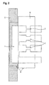
- Fig. 2 shows another embodiment in which the contacting of the intermediate element 1 by means of a plug connection to the busbar 2 takes place.
- one or more contact straps cohesively, for example, by welding, clinching, soldering, etc, attached.
- the outgoing direction of these contacts is preferably rotated by 90 ° relative to the direction of travel of the rail.
- These contact tabs are preferably already encapsulated in the manufacturing process of the potential distribution system below with a molding compound made of plastic. On the one hand, this serves to insulate and protect the contact tabs, on the other hand, the overmoulding, as in connection with the following exemplary embodiments, can also be used as a plug housing.
- the contact tab can be one or more parts in the departure.
- the protective housing 5 is advantageously divided into several chambers. If not all contacts are used depending on the equipment variants, the unused chambers or contacts can be closed with a blanking plug.
- Fig. 3 shows an embodiment in which the intermediate element is designed as an intermediate connector 1a.
- the adapter then also contains the fuse box.
- the box may consist of individual securing elements 7. It is also possible to integrate several current branches and thus also several current branches into the intermediate connector. It is also possible to connect several individual adapter plugs via their housings. These individual intermediate plugs 1a can then, as in the partial view of the Fig. 3a represented by clips or plug-in device, which are as appropriate plug-in elements 8a and recesses 8b in the intermediate connector housing or introduced, are connected together.
- it is also possible retrofits by removing the blind plug on the unused rail side plug-in elements for the adapter plug and inserting additional intermediate plugs make or cover variants.
- the wiring harness for the consumers to be connected is then simply mounted on the output side of a contact tab 9 of the intermediate connector.
- the contact of the intermediate plug with the busbar is also via a plug-in contact tab 10.
- the housing of the rail-side contact tab 10 and the housing 1a of the intermediate plug fit into each other and can be additionally formed with a locking function that supports a secure mechanical existence of the connector.
- the intermediate connector with the integrated fuses may also be integral with a plurality of parallel current branches, e.g. as punched grid solution.
- FIG Fig. 4 Another embodiment of the potential distribution system is shown in FIG Fig. 4 shown.
- the potential distribution system is designed as a double rail system.
- the two busbars 2a, 2b to be contacted may in this case preferably be integrated in a housing 5.
- the outgoing from the busbars contact tabs 10 on different sides of the rails, once on top of the rail 2a and once below the other rail 2b, attached.
- the potentials of these rails can be connected, for example, to the standardized terminals 30, that is to say the input of the battery plus, and to the potential of the terminal 15, that is to say the output for ignition or travel switch, or to the switched terminal 30.
- fuses are used on the top and bottom.
- the potential distribution on the two busbars can also be selected such that one busbar is at the potential of the terminal 30, while the other busbar is at the potential of the terminal 31, ie return to the battery or minus or ground to the battery.
- Such Massesch entry is used for example in on-board networks of commercial vehicles. It would be sufficient if a fuse was integrated at the connection to the busbar with the potential of the terminal 30, a second fuse in the ground current path can be omitted.
- the two busbar housings to be laid side by side are matched to each other, so that, for example, the housing of one busbar projects beyond the housing of the other busbar so that the projecting height is sufficient to make contact with the busbar with an intermediate plug in the region of the projecting height perform. This is especially the case when this protruding height is greater than the height of the intermediate connector.
- control devices can also be connected directly to the rail system.
- two or more rails can be used in a plane, which then several potentials can be distributed.
- the terminal straps can be arranged either offset laterally or one above the other.
Abstract
Description
- Die Erfindung betrifft ein Potentialverteilungssystem für Kraftfahrzeuge mit dem die etablierten Kabelbäume verschlankt werden können.
- Die Hochstromverteilung in Fahrzeugen erfolgt in der Regel über flexible oder hochflexible Rundleiter, die in Bündeln zusammengeschlossen werden. Diese Art Kabelbäume sind biegeschlaff und benötigen daher oft einen zusätzlichen formstabilen Kabelkanal. Die Kontaktierung der Kabelbäume kann nur an fest vorgesehenen Ausleitungen aus dem Kabelbaum und aus dem eventuell vorhandenen Kabelkanal vorgenommen werden. Zwischenabgriffe sind in der Regel nicht oder doch nur mit sehr hohem Aufwand möglich, da sie konstruktionsmäßig nicht vorgesehen und nicht gewollt sind.
- In einzelnen Fällen werden auch vorgeformte, starre Elemente zur Versteifung des Kabelbaumes eingesetzt. Ein Beispiel hierfür ist aus der Siemens Patentschrift
DE 3609704 C2 bekannt. Die Versteifung wird hier durch zusätzliche Formelemente aus Kunststoff erreicht, auf die der Kabelbaum aufgebunden wird. Die Kontaktierung der einzelnen Leitungen des Kabelbaumes erfolgt an speziell vorgesehenen Ausleitungen oder an konstruktiv vorgesehenen Steckverbindungen. - Bei Halogenbeleuchtungen für die Raumausleuchtung von Zimmern in Gebäuden sind ebenfalls Potentialverteilungssysteme für 12 Volt Gleichspannung bekannt. Um den sehr unterschiedlichen Raumaufteilungen in Gebäuden gerecht zu werden, hat man hier bereits flexibel konfektionierbare Verteilungssysteme vorgeschlagen. Ein Beispiel für ein derartiges Potentialverteilungssystem ist aus der
DE 10017484 C2 bekannt. Hier erfolgt die Potentialverteilung mit einem Schienenstecksystem. Die Leiterbahnstruktur befindet sich hierbei auf einem Kunststoffträger der einzelnen Schienensegmente. Die Schienensegmente untereinander werden mit Verbindungselementen zu dem gewünschten Gesamtlayout des Potentialverteilungssystems verbunden. Der Anschluss der Halogenleuchten soll über Steckverbinder erfolgen, die vergleichbar den Verbindungselementen auf die Enden der Schienensegmente aufgesteckt werden. - Auch bekannt ist die Verwendung von Anschlussboxen bzw. von Verteilerdosen für Stromschienen. In der
EP 0722200 B1 wird beispielsweise vorgeschlagen an einem Schienensystem Ansteckmöglichkeiten für die Abzweigung von Kabelbäumen vorzusehen. Das Gehäuse des Schienensystems und die Ansteckmöglichkeiten sind hierbei aus einem Kunstharz gefertigt, so dass die Ansteckmöglichkeit mit dem Kunststoffgehäuse des Schienensystems zusammen gegossen werden kann. Auch vorbekannt sind nach derEP 0722200 B1 Verteilerdosen aus einem Kunststoffgehäuse, wobei die Verteilerdose gleichzeitig als Sicherungsdose ausgebildet ist. - In Kraftfahrzeugbordnetzen blieben bisher Schienensysteme als Ersatz für den Kabelbaum unbekannt. Dies dürfte vor allen Dingen an den höheren Kosten von Schienensystemen liegen. Aber auch technisch bieten die bekannten Schienensysteme zuwenig Vorteile für den Einsatz in Kraftfahrzeugbordnetzen. Hauptnachteil ist die noch als unzureichend empfundene, mangelnde Flexibilität hinsichtlich der Ableitungsmöglichkeiten. Insbesondere die Absicherung der Ableitungen lässt bei den bekannten Schienensystemen oftmals keine Flexibilität zu. Gerade dies ist aber für die Nachrüstbarkeit mit zusätzlichen Verbrauchern oder für die Handhabung der verschiedenen Ausrüstungsvarianten der Kraftfahrzeuge für die Bordnetze in diesen Kraftfahrzeugen wünschenswert.
- Erfindungsgemäße Aufgabe ist es daher, ein Schienensystem vorzuschlagen, das speziell für die Potentialverteilung in Kraftfahrzeugen geeignet ist.
- Die Lösung gelingt mit einem Potentialverteilungssystem nach Anspruch 1. Weitere Ausführungsbeispiele sind in den Unteransprüchen und in der folgenden Beschreibung offenbart.
- Die Lösung gelingt hauptsächlich mit einem Schienensystem, das auf Vorrat an den Stromschienen einen zahlenmäßigen Überschuss an Anschlussmöglichkeiten für weitere Ableitungen vorsieht. Die nicht benötigten Anschlussmöglichkeiten können mit einem Blindstopfen abgeschlossen werden und die benötigten Anschlussmöglichkeiten werden über ein Zwischenelement kontaktiert, wobei das Zwischenelement als Sicherungsbox oder als Zwischenstecker mit integrierten Sicherungen ausgebildet sein kann.
- Das Schienensystem kann auch als Doppelschienensystem ausgebildet sein. Eine Schiene kann dann als Masserückführung geschaltet sein. Das Schienensystem ist dann besonders für den Nutzfahrzeugbereich geeignet, in dem Bordnetze mit Masserückführung eingesetzt werden.
- Ausführungsbeispiele werden im Folgenden anhand von Figuren näher erläutert.
- Dabei zeigen:
- Fig. 1
- ein erstes Ausführungsbeispiel mit einem anschraubbaren Zwischenelement,
- Fig. 2
- ein weiteres Ausführungsbeispiel mit einem steckbaren Zwischenelement,
- Fig. 3
- ein weiteres Ausführungsbeispiel mit einem Zwischenstecker,
- Fig. 4
- ein Ausführungsbeispiel für ein Doppelschienensystem,
- Fig. 5
- ein weiteres Ausführungsbeispiel für ein Doppelschienensystem.
-
Fig. 1 zeigt ein erstes Ausführungsbeispiel des Potentialverteilungssystem, bei dem ein Zwischenelement 1 als Sicherungsbox ausgebildet ist und wobei das Zwischenelement über eine Schraubverbindung 3 mit der Stromschiene 2 kontaktiert wird. Die Schraubverbindung wird vorzugsweise dann eingesetzt, wenn die Stromschiene am Fahrzeugunterboden eines Kraftfahrzeugs verläuft und eine Durchkontaktierung durch den Unterboden erfolgt. Dies kann am Ende der Schiene aber auch entlang des Verlaufs der Fall sein. Der Schraubanschluss wird stoffschlüssig mit der Schiene verbunden, z.B. durch Einschweißen eines Gewindebolzens in die Stromschiene. Das Zwischenelement enthält ein metallisches Stanzgitter 4, das in ein Gehäuse 5 eingefasst ist. Das Stangitter ist mit mehreren elektrischen Stromabzweigen 6 ausgebildet. In die einzelnen Stromabzweige kann bei Bedarf auch gleichzeitig ein Sicherungselement 7, vorzugsweise als Querschnittsverjüngung im Stromabzweig des Stanzgitters enthalten sein. -
Fig. 2 zeigt ein anderes Ausführungsbeispiel, bei dem die Kontaktierung des Zwischenelementes 1 mittels einer Steckverbindung an der Stromschiene 2 erfolgt. Auf der Schiene werden, je nach zu erwartender Strombelastung, ein oder mehrere Kontaktlaschen stoffschlüssig, z.B. durch schweißen, clinchen, löten, etc, angebracht. Die Abgangsrichtung dieser Kontakte ist vorzugsweise um 90° gegenüber der Laufrichtung der Schiene gedreht. Diese Kontaktlaschen werden vorzugsweise bereits beim Herstellungsprozess des Potentialverteilungssystems im Folgenden mit einer Moldmasse aus Kunststoff umspritzt. Dies dient einerseits zur Isolation und zum Schutz der Kontaktlaschen, andererseits kann die Umspritzung, wie im Zusammenhang mit den nachfolgenden Ausführungsbeispielen von Bedeutung auch als Steckergehäuse genutzt werden. Die Kontaktlasche kann dabei im Abgang ein- oder mehrteilig sein. Bei mehrteiligen Abgängen ist das Schutzgehäuse 5 vorteilhafterweise in mehrere Kammern aufgeteilt. Werden abhängig von den Ausstattungsvarianten nicht alle Kontakte genutzt, können die ungenutzten Kammern oder Kontakte mit einem Blindstopfen verschlossen werden. -
Fig. 3 zeigt ein Ausführungsbeispiel, bei dem das Zwischenelement als Zwischenstecker 1a ausgebildet ist. Der Zwischenstecker enthält dann auch die Sicherungsbox. Hierbei kann die Box aus einzelnen Sicherungselementen 7 bestehen. Es können auch mehrere Stromabzweige und damit auch mehrere Stromabzweige in den Zwischenstecker integriert sein. Es ist auch möglich mehrere einzelne Zwischenstecker über ihre Gehäuse miteinander zu verbinden. Diese einzelnen Zwischenstecker 1a können dann, wie in der Teildarstellung derFig. 3a dargestellt, durch Clips- oder Steckvorrichtung, die als passende Steckelemente 8a und Aussparungen 8b in die Zwischensteckergehäuse an- bzw. eingebracht sind, miteinander verbunden werden. Hierdurch ist es auch möglich, Nachrüstungen, durch Entfernen der Blindstopfen an den unbenutzten schienenseitigen Steckelementen für die Zwischenstecker und Einsetzen von weiteren Zwischensteckern, vorzunehmen oder Varianten abzudecken. - Der Leitungssatz für die anzuschließenden Verbraucher wird dann einfach ausgangsseitig an einer Kontaktlasche 9 des Zwischensteckers montiert. Die Kontaktierung des Zwischensteckers mit der Stromschiene erfolgt ebenfalls über eine steckbare Kontaktlasche 10. Das Gehäuse der schienenseitigen Kontaktlasche 10 und das Gehäuse 1a des Zwischensteckers greifen passgenau ineinander und können zusätzlich mit einer Rastfunktion ausgebildet sein, die ein sicheres mechanisches Bestehen der Steckverbindung unterstützt.
- Der Zwischenstecker mit den integrierten Sicherungen kann natürlich auch einteilig mit mehreren, parallelen Stromabzweigen, z.B. als Stanzgitterlösung, ausgeführt werden.
- Ein weiteres Ausführungsbeispiel des Potentialverteilungssystems ist in
Fig. 4 dargestellt. Hier ist das Potentialverteilungssystem als Doppelschienensystem ausgebildet. In diesem Fall werden zwei Schienen 2a, 2b mit einem Zwischenelement, das inFig. 4 als Zwischenstecker 1a ausgebildet ist, gleichzeitig kontaktiert. Die beiden zu kontaktierenden Stromschienen 2a, 2b können hierbei vorzugsweise in ein Gehäuse 5 integriert sein. Hierzu werden die von den Stromschienen abgehenden Kontaktlaschen 10 auf verschiednen Seiten der Schienen, einmal oben auf der Schiene 2a und einmal unten an der weiteren Schiene 2b, angebracht. Die Potentiale dieser Schienen können zum Bsp. mit der genormten Klemmen 30, also Eingang von Batterieplus, und mit dem Potential der Klemme 15, also Ausgang nach Zünd- bzw. Fahrtschalter, oder mit der geschalteten Klemme 30 verbunden sein. In diesem Fall werden ober- wie unterseitig Sicherungen eingesetzt. - Alternativ kann die Potentialverteilung auf die beiden Stromschienen auch derart gewählt werden, dass eine Stromschiene auf dem Potential der Klemme 30 liegt, während die andere Stromschiene auf dem Potential der Klemme 31,also Rückleitung zur Batterie oder Minus bzw. Masse zur Batterie, liegt. Eine solche Masserückführung wird beispielsweise in Bordnetzen von Nutzfahrzeugen eingesetzt. Hierbei wäre es ausreichend, wenn an der Verbindung zur Stromschiene mit dem Potential der Klemme 30 eine Sicherung integriert wäre, eine zweite Absicherung im Massestrompfad kann entfallen.
- Will man bei einer Mehrschienenanordnung die Stromschienen nicht als Doppelschienensystem zusammenfassen, kann man natürlich auch zwei Einzelschienen mit jeweils getrennten Gehäusen nebeneinander verlegen. Dieser Sachverhalt ist in
Fig. 5 dargestellt. Vorzugsweise sind die beiden nebeneinander zu verlegenden Stromschienengehäuse aufeinander abgestimmt, so dass zum Beispiel das Gehäuse der einen Stromschiene das Gehäuse der anderen Stromschiene in der Höhe überragt, derart dass die überstehende Höhe ausreicht, um eine Kontaktierung der Stromschiene mit einem Zwischenstecker im Bereich der überstehenden Höhe durchzuführen. Das ist insbesondere dann der Fall wenn diese überstehende Höhe größer als die Höhe der Zwischenstecker ist. - Anstelle von Zwischenelementen oder Zwischensteckern können natürlich auch Steuergeräte unmittelbar mit dem Schienensystem verbunden werden.
- Weiterhin können auch zwei oder mehrere Schienen in einer Ebene eingesetzt werden, wodurch dann auch mehrere Potentiale verteilt werden können. Hierbei können die Anschlusslaschen entweder seitlich versetzt angeordnet sein oder übereinander.
Claims (8)
- Potentialverteilungssystem für Kraftfahrzeuge mit- einem potentialführenden Schienensystem (2, 2a, 2b), das auf Vorrat an der Stromschiene einen zahlenmäßigen Überschuss an Anschlussmöglichkeiten für weitere Ableitungen hat,
dadurch gekennzeichnet, dass- die anzuschließenden Verbraucher über ein Zwischenelement (1, 1a) an das Stromschienensystem angeschlossen werden und wobei das Zwischenelement als Sicherungsbox (1) oder als Zwischenstecker (1a) mit integrierten Sicherungen ausgebildet ist. - Potentialverteilungssystem nach Anspruch 1, dadurch gekennzeichnet, dass ein Schraubanschluss stoffschlüssig mit der Stromschiene verbunden ist.
- Potentialverteilungssystem nach Anspruch 2, dadurch gekennzeichnet, dass das Zwischenelement über die Schraubverbindung mit der Stromschiene kontaktiert ist
- Potentialverteilungssystem nach einem der Ansprüche 1 bis 3, dadurch gekennzeichnet, dass das Schienensystem als Doppelschienensystem ausgebildet ist.
- Potentialverteilungssystem nach einem der Ansprüche 1 bis 4, dadurch gekennzeichnet, dass die Kontaktlaschen (10) im Zwischenelement als Stanzgitter ausgebildet sind.
- Potentialverteilungssystem nach einem der Ansprüche 1 bis 5, dadurch gekennzeichnet, dass die Kontaktlaschen des Zwischenelements und der Anschluss der Kontaktlaschen an den Stromschienen in einem gemeinsamen Gehäuse (5) vergossen sind.
- Potentialverteilungssystem nach einem der Ansprüche 1 bis 6, dadurch gekennzeichnet, dass bei einem Mehrschienensystem die Stromschienengehause aufeinander abgestimmt sind.
- Potentialverteilungssystem nach Anspruch 6 oder 7, dadurch gekennzeichnet, dass ein Stromschienengehause das andere Stromschienengehause mindestens um die Höhe eines Zwischensteckers überragt.
Priority Applications (1)
| Application Number | Priority Date | Filing Date | Title |
|---|---|---|---|
| EP19168557.7A EP3534466B1 (de) | 2006-03-03 | 2007-03-01 | Anordnung zur stromverteilung sowie deren kontaktierung und absicherung der abgehenden leitungen |
Applications Claiming Priority (3)
| Application Number | Priority Date | Filing Date | Title |
|---|---|---|---|
| DE102006009936A DE102006009936A1 (de) | 2006-03-03 | 2006-03-03 | Anordnung zur Stromverteilung sowie deren Kontaktierung und Absicherung der abgehenden Leitungen |
| PCT/EP2007/001741 WO2007101596A1 (de) | 2006-03-03 | 2007-03-01 | Anordnung zur stromverteilung sowie deren kontaktierung und absicherung der abgehenden leitungen |
| EP07711718.2A EP1992047B1 (de) | 2006-03-03 | 2007-03-01 | Anordnung zur stromverteilung sowie deren kontaktierung und absicherung der abgehenden leitungen |
Related Parent Applications (1)
| Application Number | Title | Priority Date | Filing Date |
|---|---|---|---|
| EP07711718.2A Division EP1992047B1 (de) | 2006-03-03 | 2007-03-01 | Anordnung zur stromverteilung sowie deren kontaktierung und absicherung der abgehenden leitungen |
Related Child Applications (1)
| Application Number | Title | Priority Date | Filing Date |
|---|---|---|---|
| EP19168557.7A Division EP3534466B1 (de) | 2006-03-03 | 2007-03-01 | Anordnung zur stromverteilung sowie deren kontaktierung und absicherung der abgehenden leitungen |
Publications (3)
| Publication Number | Publication Date |
|---|---|
| EP2790272A2 true EP2790272A2 (de) | 2014-10-15 |
| EP2790272A3 EP2790272A3 (de) | 2014-12-17 |
| EP2790272B1 EP2790272B1 (de) | 2019-05-01 |
Family
ID=38091698
Family Applications (3)
| Application Number | Title | Priority Date | Filing Date |
|---|---|---|---|
| EP19168557.7A Active EP3534466B1 (de) | 2006-03-03 | 2007-03-01 | Anordnung zur stromverteilung sowie deren kontaktierung und absicherung der abgehenden leitungen |
| EP07711718.2A Active EP1992047B1 (de) | 2006-03-03 | 2007-03-01 | Anordnung zur stromverteilung sowie deren kontaktierung und absicherung der abgehenden leitungen |
| EP14176369.8A Active EP2790272B1 (de) | 2006-03-03 | 2007-03-01 | Anordnung zur Stromverteilung sowie deren Kontaktierung und Absicherung der abgehenden Leitungen |
Family Applications Before (2)
| Application Number | Title | Priority Date | Filing Date |
|---|---|---|---|
| EP19168557.7A Active EP3534466B1 (de) | 2006-03-03 | 2007-03-01 | Anordnung zur stromverteilung sowie deren kontaktierung und absicherung der abgehenden leitungen |
| EP07711718.2A Active EP1992047B1 (de) | 2006-03-03 | 2007-03-01 | Anordnung zur stromverteilung sowie deren kontaktierung und absicherung der abgehenden leitungen |
Country Status (6)
| Country | Link |
|---|---|
| US (1) | US8142235B2 (de) |
| EP (3) | EP3534466B1 (de) |
| CN (1) | CN101395762B (de) |
| DE (1) | DE102006009936A1 (de) |
| ES (3) | ES2922496T3 (de) |
| WO (1) | WO2007101596A1 (de) |
Families Citing this family (11)
| Publication number | Priority date | Publication date | Assignee | Title |
|---|---|---|---|---|
| JP5170305B2 (ja) | 2009-04-03 | 2013-03-27 | 富士通株式会社 | 移動局、無線基地局および無線通信方法 |
| DE102010050124B3 (de) * | 2010-11-03 | 2012-01-26 | Audi Ag | Stromverteilereinrichtung für ein Hochspannungsnetz und Kraftfahrzeug |
| DE102011051320B4 (de) * | 2011-06-24 | 2013-09-05 | Audio Ohm Di Tonani Caterina & C. S.R.L. | Stecksicherung mit verbesserter Auslösecharakteristik |
| DE102012218826A1 (de) * | 2012-10-16 | 2014-04-17 | Tyco Electronics Amp Gmbh | Elektrischer Potenzialverteilungs-Steckadapter, Verfahren zum Bestücken einer elektrischen Verteilereinrichtung |
| JP6308439B2 (ja) * | 2015-02-10 | 2018-04-11 | 株式会社オートネットワーク技術研究所 | 電源分配装置 |
| DE102015202753A1 (de) * | 2015-02-16 | 2016-08-18 | Bayerische Motoren Werke Aktiengesellschaft | Hochvoltsystem |
| US9774179B1 (en) * | 2017-03-30 | 2017-09-26 | Ford Global Technologies, Llc | Fused T-splice wiring |
| US10217693B1 (en) * | 2017-08-29 | 2019-02-26 | Nio Usa, Inc. | Methods and systems for high voltage component cooling in electric vehicle for fast charge |
| US10608301B2 (en) | 2017-08-29 | 2020-03-31 | Nio Usa, Inc. | Power electronics with integrated busbar cooling |
| DE102021112304B4 (de) * | 2021-05-11 | 2023-03-30 | Lisa Dräxlmaier GmbH | Kontakteinrichtung und kontaktsystem für eine doppelstromschiene |
| DE102022204677A1 (de) * | 2022-05-12 | 2023-11-16 | Leoni Bordnetz-Systeme Gmbh | Vorrichtung zur elektrischen Leistungsverteilung für ein Kraftfahrzeug |
Citations (3)
| Publication number | Priority date | Publication date | Assignee | Title |
|---|---|---|---|---|
| DE3609704C2 (de) | 1986-03-20 | 1995-04-20 | Siemens Ag | Kabelbaum für Kraftfahrzeuge |
| EP0722200B1 (de) | 1995-01-10 | 2001-03-21 | Sumitomo Wiring Systems, Ltd. | Abzweigdose |
| DE10017484C2 (de) | 2000-04-07 | 2003-10-02 | Ralf Wieduwilt | Niederspannungs-Verteilungssystem |
Family Cites Families (15)
| Publication number | Priority date | Publication date | Assignee | Title |
|---|---|---|---|---|
| US3952209A (en) * | 1974-09-09 | 1976-04-20 | International Telephone And Telegraph Corporation | Electrical system for automotive vehicles and the like |
| IT1030225B (it) * | 1975-02-27 | 1979-03-30 | Fiat Spa | Impianto elettrico in particolare per autoveicoli |
| JPS63109244U (de) * | 1987-01-08 | 1988-07-14 | ||
| DE3930153A1 (de) * | 1989-09-09 | 1991-03-21 | Rheydt Kabelwerk Ag | Verkabelungssystem fuer fahrzeuge |
| US5490794A (en) * | 1993-11-05 | 1996-02-13 | Sumitomo Wiring Systems, Ltd. | Branch joint box |
| US5676558A (en) * | 1995-10-02 | 1997-10-14 | Mayer; E. Howard | Reduced cable requiring, fusible bus duct system and method for providing electrical energy to houses and buildings and the like |
| US5643693A (en) * | 1995-10-30 | 1997-07-01 | Yazaki Corporation | Battery-mounted power distribution module |
| DE19646264C2 (de) * | 1996-11-09 | 2000-10-26 | Wilhelm Pudenz Gmbh Elektrotec | Schmelzleiteraufbau |
| AU6049498A (en) * | 1997-01-30 | 1998-08-25 | Whitaker Corporation, The | Power and signal distribution for automotive electronics using area and feature modules |
| DE19732697C2 (de) * | 1997-07-30 | 2001-10-04 | Daimler Chrysler Ag | Vorrichtung zum Abzweigen von Kabeln |
| DE69726158T2 (de) * | 1997-12-17 | 2004-08-26 | Meccanotecnica Codognese S.P.A., Codogno | Starkstromschutzvorrichtung |
| DE19906000B4 (de) | 1999-02-15 | 2006-09-28 | Volkswagen Ag | Energieanschlussleiste für Kraftfahrzeuge |
| JP2001054223A (ja) * | 1999-08-06 | 2001-02-23 | Toyota Motor Corp | ヒューズ装置 |
| US20020132515A1 (en) * | 2001-03-19 | 2002-09-19 | Chin-Chuan Hong | Electrical plug with circuit-breaking capability |
| JP2002329453A (ja) * | 2001-04-27 | 2002-11-15 | Yazaki Corp | 連鎖型ヒューズ組立体およびそのレイアウト方法 |
-
2006
- 2006-03-03 DE DE102006009936A patent/DE102006009936A1/de not_active Withdrawn
-
2007
- 2007-03-01 CN CN2007800075538A patent/CN101395762B/zh not_active Expired - Fee Related
- 2007-03-01 ES ES19168557T patent/ES2922496T3/es active Active
- 2007-03-01 WO PCT/EP2007/001741 patent/WO2007101596A1/de active Application Filing
- 2007-03-01 US US12/281,272 patent/US8142235B2/en not_active Expired - Fee Related
- 2007-03-01 EP EP19168557.7A patent/EP3534466B1/de active Active
- 2007-03-01 ES ES14176369T patent/ES2727669T3/es active Active
- 2007-03-01 EP EP07711718.2A patent/EP1992047B1/de active Active
- 2007-03-01 ES ES07711718.2T patent/ES2502516T3/es active Active
- 2007-03-01 EP EP14176369.8A patent/EP2790272B1/de active Active
Patent Citations (3)
| Publication number | Priority date | Publication date | Assignee | Title |
|---|---|---|---|---|
| DE3609704C2 (de) | 1986-03-20 | 1995-04-20 | Siemens Ag | Kabelbaum für Kraftfahrzeuge |
| EP0722200B1 (de) | 1995-01-10 | 2001-03-21 | Sumitomo Wiring Systems, Ltd. | Abzweigdose |
| DE10017484C2 (de) | 2000-04-07 | 2003-10-02 | Ralf Wieduwilt | Niederspannungs-Verteilungssystem |
Also Published As
| Publication number | Publication date |
|---|---|
| CN101395762A (zh) | 2009-03-25 |
| CN101395762B (zh) | 2011-04-13 |
| EP3534466A1 (de) | 2019-09-04 |
| US8142235B2 (en) | 2012-03-27 |
| US20090050366A1 (en) | 2009-02-26 |
| WO2007101596A1 (de) | 2007-09-13 |
| EP3534466B1 (de) | 2022-07-06 |
| EP2790272B1 (de) | 2019-05-01 |
| ES2727669T3 (es) | 2019-10-17 |
| ES2922496T3 (es) | 2022-09-15 |
| ES2502516T3 (es) | 2014-10-03 |
| DE102006009936A1 (de) | 2007-09-06 |
| EP1992047B1 (de) | 2014-07-16 |
| EP2790272A3 (de) | 2014-12-17 |
| EP1992047A1 (de) | 2008-11-19 |
Similar Documents
| Publication | Publication Date | Title |
|---|---|---|
| EP2790272B1 (de) | Anordnung zur Stromverteilung sowie deren Kontaktierung und Absicherung der abgehenden Leitungen | |
| EP2473377B1 (de) | Modularer stromverteiler | |
| DE4438800C1 (de) | Anschlußklemmenblock mit Elektronikmodul | |
| DE19548961C2 (de) | Elektrischer Anschlußkasten | |
| DE102012214366B4 (de) | Schaltvorrichtung für einen Stromschienen-basierten Fahrzeugstromverteiler | |
| EP0209072B1 (de) | Einrichtung für ein Kraftfahrzeug | |
| EP3006252B1 (de) | Hochvoltverteiler für ein hybrid- oder elektrofahrzeug | |
| DE2409660A1 (de) | Elektrische schalt-, steuer- und/oder regeleinrichtung fuer elektrische geraete in einem fahrzeug | |
| WO2017046370A1 (de) | Stromverteiler mit aufsteckbarer elektronik | |
| DE10248012B4 (de) | Struktur zur Verbindung von Batterieanschlüssen mit Sammelschienen | |
| DE102010042158A1 (de) | Elektrisches Verteilergehäuse | |
| DE102012014519B3 (de) | Verteilerbox | |
| EP1830376B1 (de) | Vorrichtung zur Stromverteilung | |
| DE102006045859B4 (de) | Potentialverteiler für Kraftfahrzeuge | |
| EP1787358B1 (de) | Strom-einspeisemodul mit käfig-zugfederklemmen | |
| DE102019103531B4 (de) | Überspannungsableiteranordnung mit in einem gemeinsamen Gehäuse befindlichen, vorkonfektionierten und elektrisch verschalteten Überspannungsableitern | |
| DE102009036599A1 (de) | Hochstromverkabelung | |
| EP2073314B1 (de) | Anordnung zum elektrisch leitenden Verbinden von elektrischen Leltern | |
| DE2340773A1 (de) | Uebergabesteckverbindung | |
| DE202018006111U1 (de) | Überspannungsableiteranordnung mit in einem gemeinsamen Gehäuse befindlichen, vorkonfektionierten und elektrisch verschalteten Überspannungsableitern | |
| DE102015205450B4 (de) | Hauptsicherungsbox , mit einer Mehrfachsicherung, zur Befestigung an einer Bordnetz-Batterie eines Kraftfahrzeugs | |
| WO1999006242A1 (de) | Potentialverteilungssystem zur potentialverteilung an verbraucher sowie geeigneter verbinder | |
| DE10000336A1 (de) | Modulare Zentralelektrik für Kraftfahrzeuge | |
| DE202021105885U1 (de) | Kabelanschlusskasten mit Nullleitertrennung | |
| EP1562268A1 (de) | Elektrisches Verbindungselement |
Legal Events
| Date | Code | Title | Description |
|---|---|---|---|
| PUAI | Public reference made under article 153(3) epc to a published international application that has entered the european phase |
Free format text: ORIGINAL CODE: 0009012 |
|
| 17P | Request for examination filed |
Effective date: 20140709 |
|
| AC | Divisional application: reference to earlier application |
Ref document number: 1992047 Country of ref document: EP Kind code of ref document: P |
|
| AK | Designated contracting states |
Kind code of ref document: A2 Designated state(s): AT BE BG CH CY CZ DE DK EE ES FI FR GB GR HU IE IS IT LI LT LU LV MC MT NL PL PT RO SE SI SK TR |
|
| PUAL | Search report despatched |
Free format text: ORIGINAL CODE: 0009013 |
|
| AK | Designated contracting states |
Kind code of ref document: A3 Designated state(s): AT BE BG CH CY CZ DE DK EE ES FI FR GB GR HU IE IS IT LI LT LU LV MC MT NL PL PT RO SE SI SK TR |
|
| RIC1 | Information provided on ipc code assigned before grant |
Ipc: H01R 31/02 20060101ALI20141111BHEP Ipc: H01R 9/24 20060101AFI20141111BHEP |
|
| R17P | Request for examination filed (corrected) |
Effective date: 20150410 |
|
| RBV | Designated contracting states (corrected) |
Designated state(s): AT BE BG CH CY CZ DE DK EE ES FI FR GB GR HU IE IS IT LI LT LU LV MC MT NL PL PT RO SE SI SK TR |
|
| GRAP | Despatch of communication of intention to grant a patent |
Free format text: ORIGINAL CODE: EPIDOSNIGR1 |
|
| STAA | Information on the status of an ep patent application or granted ep patent |
Free format text: STATUS: GRANT OF PATENT IS INTENDED |
|
| INTG | Intention to grant announced |
Effective date: 20181129 |
|
| GRAS | Grant fee paid |
Free format text: ORIGINAL CODE: EPIDOSNIGR3 |
|
| GRAA | (expected) grant |
Free format text: ORIGINAL CODE: 0009210 |
|
| STAA | Information on the status of an ep patent application or granted ep patent |
Free format text: STATUS: THE PATENT HAS BEEN GRANTED |
|
| AC | Divisional application: reference to earlier application |
Ref document number: 1992047 Country of ref document: EP Kind code of ref document: P |
|
| AK | Designated contracting states |
Kind code of ref document: B1 Designated state(s): AT BE BG CH CY CZ DE DK EE ES FI FR GB GR HU IE IS IT LI LT LU LV MC MT NL PL PT RO SE SI SK TR |
|
| REG | Reference to a national code |
Ref country code: GB Ref legal event code: FG4D Free format text: NOT ENGLISH |
|
| REG | Reference to a national code |
Ref country code: CH Ref legal event code: EP Ref country code: AT Ref legal event code: REF Ref document number: 1128170 Country of ref document: AT Kind code of ref document: T Effective date: 20190515 |
|
| REG | Reference to a national code |
Ref country code: DE Ref legal event code: R096 Ref document number: 502007016665 Country of ref document: DE |
|
| REG | Reference to a national code |
Ref country code: IE Ref legal event code: FG4D Free format text: LANGUAGE OF EP DOCUMENT: GERMAN |
|
| REG | Reference to a national code |
Ref country code: NL Ref legal event code: MP Effective date: 20190501 |
|
| REG | Reference to a national code |
Ref country code: LT Ref legal event code: MG4D |
|
| REG | Reference to a national code |
Ref country code: ES Ref legal event code: FG2A Ref document number: 2727669 Country of ref document: ES Kind code of ref document: T3 Effective date: 20191017 |
|
| PG25 | Lapsed in a contracting state [announced via postgrant information from national office to epo] |
Ref country code: NL Free format text: LAPSE BECAUSE OF FAILURE TO SUBMIT A TRANSLATION OF THE DESCRIPTION OR TO PAY THE FEE WITHIN THE PRESCRIBED TIME-LIMIT Effective date: 20190501 Ref country code: PT Free format text: LAPSE BECAUSE OF FAILURE TO SUBMIT A TRANSLATION OF THE DESCRIPTION OR TO PAY THE FEE WITHIN THE PRESCRIBED TIME-LIMIT Effective date: 20190901 Ref country code: SE Free format text: LAPSE BECAUSE OF FAILURE TO SUBMIT A TRANSLATION OF THE DESCRIPTION OR TO PAY THE FEE WITHIN THE PRESCRIBED TIME-LIMIT Effective date: 20190501 Ref country code: LT Free format text: LAPSE BECAUSE OF FAILURE TO SUBMIT A TRANSLATION OF THE DESCRIPTION OR TO PAY THE FEE WITHIN THE PRESCRIBED TIME-LIMIT Effective date: 20190501 Ref country code: FI Free format text: LAPSE BECAUSE OF FAILURE TO SUBMIT A TRANSLATION OF THE DESCRIPTION OR TO PAY THE FEE WITHIN THE PRESCRIBED TIME-LIMIT Effective date: 20190501 |
|
| PG25 | Lapsed in a contracting state [announced via postgrant information from national office to epo] |
Ref country code: GR Free format text: LAPSE BECAUSE OF FAILURE TO SUBMIT A TRANSLATION OF THE DESCRIPTION OR TO PAY THE FEE WITHIN THE PRESCRIBED TIME-LIMIT Effective date: 20190802 Ref country code: BG Free format text: LAPSE BECAUSE OF FAILURE TO SUBMIT A TRANSLATION OF THE DESCRIPTION OR TO PAY THE FEE WITHIN THE PRESCRIBED TIME-LIMIT Effective date: 20190801 Ref country code: LV Free format text: LAPSE BECAUSE OF FAILURE TO SUBMIT A TRANSLATION OF THE DESCRIPTION OR TO PAY THE FEE WITHIN THE PRESCRIBED TIME-LIMIT Effective date: 20190501 |
|
| PG25 | Lapsed in a contracting state [announced via postgrant information from national office to epo] |
Ref country code: IS Free format text: LAPSE BECAUSE OF FAILURE TO SUBMIT A TRANSLATION OF THE DESCRIPTION OR TO PAY THE FEE WITHIN THE PRESCRIBED TIME-LIMIT Effective date: 20190901 |
|
| PG25 | Lapsed in a contracting state [announced via postgrant information from national office to epo] |
Ref country code: DK Free format text: LAPSE BECAUSE OF FAILURE TO SUBMIT A TRANSLATION OF THE DESCRIPTION OR TO PAY THE FEE WITHIN THE PRESCRIBED TIME-LIMIT Effective date: 20190501 Ref country code: SK Free format text: LAPSE BECAUSE OF FAILURE TO SUBMIT A TRANSLATION OF THE DESCRIPTION OR TO PAY THE FEE WITHIN THE PRESCRIBED TIME-LIMIT Effective date: 20190501 Ref country code: RO Free format text: LAPSE BECAUSE OF FAILURE TO SUBMIT A TRANSLATION OF THE DESCRIPTION OR TO PAY THE FEE WITHIN THE PRESCRIBED TIME-LIMIT Effective date: 20190501 Ref country code: EE Free format text: LAPSE BECAUSE OF FAILURE TO SUBMIT A TRANSLATION OF THE DESCRIPTION OR TO PAY THE FEE WITHIN THE PRESCRIBED TIME-LIMIT Effective date: 20190501 |
|
| REG | Reference to a national code |
Ref country code: DE Ref legal event code: R097 Ref document number: 502007016665 Country of ref document: DE |
|
| PLBE | No opposition filed within time limit |
Free format text: ORIGINAL CODE: 0009261 |
|
| STAA | Information on the status of an ep patent application or granted ep patent |
Free format text: STATUS: NO OPPOSITION FILED WITHIN TIME LIMIT |
|
| PG25 | Lapsed in a contracting state [announced via postgrant information from national office to epo] |
Ref country code: TR Free format text: LAPSE BECAUSE OF FAILURE TO SUBMIT A TRANSLATION OF THE DESCRIPTION OR TO PAY THE FEE WITHIN THE PRESCRIBED TIME-LIMIT Effective date: 20190501 |
|
| 26N | No opposition filed |
Effective date: 20200204 |
|
| PG25 | Lapsed in a contracting state [announced via postgrant information from national office to epo] |
Ref country code: PL Free format text: LAPSE BECAUSE OF FAILURE TO SUBMIT A TRANSLATION OF THE DESCRIPTION OR TO PAY THE FEE WITHIN THE PRESCRIBED TIME-LIMIT Effective date: 20190501 |
|
| PG25 | Lapsed in a contracting state [announced via postgrant information from national office to epo] |
Ref country code: SI Free format text: LAPSE BECAUSE OF FAILURE TO SUBMIT A TRANSLATION OF THE DESCRIPTION OR TO PAY THE FEE WITHIN THE PRESCRIBED TIME-LIMIT Effective date: 20190501 |
|
| PG25 | Lapsed in a contracting state [announced via postgrant information from national office to epo] |
Ref country code: MC Free format text: LAPSE BECAUSE OF FAILURE TO SUBMIT A TRANSLATION OF THE DESCRIPTION OR TO PAY THE FEE WITHIN THE PRESCRIBED TIME-LIMIT Effective date: 20190501 |
|
| REG | Reference to a national code |
Ref country code: CH Ref legal event code: PL |
|
| REG | Reference to a national code |
Ref country code: BE Ref legal event code: MM Effective date: 20200331 |
|
| PG25 | Lapsed in a contracting state [announced via postgrant information from national office to epo] |
Ref country code: LU Free format text: LAPSE BECAUSE OF NON-PAYMENT OF DUE FEES Effective date: 20200301 |
|
| PG25 | Lapsed in a contracting state [announced via postgrant information from national office to epo] |
Ref country code: IE Free format text: LAPSE BECAUSE OF NON-PAYMENT OF DUE FEES Effective date: 20200301 Ref country code: CH Free format text: LAPSE BECAUSE OF NON-PAYMENT OF DUE FEES Effective date: 20200331 Ref country code: LI Free format text: LAPSE BECAUSE OF NON-PAYMENT OF DUE FEES Effective date: 20200331 |
|
| PG25 | Lapsed in a contracting state [announced via postgrant information from national office to epo] |
Ref country code: BE Free format text: LAPSE BECAUSE OF NON-PAYMENT OF DUE FEES Effective date: 20200331 |
|
| PGFP | Annual fee paid to national office [announced via postgrant information from national office to epo] |
Ref country code: GB Payment date: 20220321 Year of fee payment: 16 Ref country code: DE Payment date: 20220321 Year of fee payment: 16 Ref country code: AT Payment date: 20220322 Year of fee payment: 16 |
|
| PG25 | Lapsed in a contracting state [announced via postgrant information from national office to epo] |
Ref country code: MT Free format text: LAPSE BECAUSE OF FAILURE TO SUBMIT A TRANSLATION OF THE DESCRIPTION OR TO PAY THE FEE WITHIN THE PRESCRIBED TIME-LIMIT Effective date: 20190501 Ref country code: CY Free format text: LAPSE BECAUSE OF FAILURE TO SUBMIT A TRANSLATION OF THE DESCRIPTION OR TO PAY THE FEE WITHIN THE PRESCRIBED TIME-LIMIT Effective date: 20190501 |
|
| PGFP | Annual fee paid to national office [announced via postgrant information from national office to epo] |
Ref country code: FR Payment date: 20220321 Year of fee payment: 16 |
|
| PGFP | Annual fee paid to national office [announced via postgrant information from national office to epo] |
Ref country code: IT Payment date: 20220324 Year of fee payment: 16 Ref country code: ES Payment date: 20220420 Year of fee payment: 16 |
|
| PGFP | Annual fee paid to national office [announced via postgrant information from national office to epo] |
Ref country code: CZ Payment date: 20230126 Year of fee payment: 17 |
|
| REG | Reference to a national code |
Ref country code: DE Ref legal event code: R119 Ref document number: 502007016665 Country of ref document: DE |
|
| REG | Reference to a national code |
Ref country code: AT Ref legal event code: MM01 Ref document number: 1128170 Country of ref document: AT Kind code of ref document: T Effective date: 20230301 |
|
| GBPC | Gb: european patent ceased through non-payment of renewal fee |
Effective date: 20230301 |
|
| PG25 | Lapsed in a contracting state [announced via postgrant information from national office to epo] |
Ref country code: GB Free format text: LAPSE BECAUSE OF NON-PAYMENT OF DUE FEES Effective date: 20230301 |
|
| PG25 | Lapsed in a contracting state [announced via postgrant information from national office to epo] |
Ref country code: GB Free format text: LAPSE BECAUSE OF NON-PAYMENT OF DUE FEES Effective date: 20230301 Ref country code: FR Free format text: LAPSE BECAUSE OF NON-PAYMENT OF DUE FEES Effective date: 20230331 Ref country code: DE Free format text: LAPSE BECAUSE OF NON-PAYMENT OF DUE FEES Effective date: 20231003 Ref country code: AT Free format text: LAPSE BECAUSE OF NON-PAYMENT OF DUE FEES Effective date: 20230301 |