EP2785547B2 - Dichtungsprofil - Google Patents
Dichtungsprofil Download PDFInfo
- Publication number
- EP2785547B2 EP2785547B2 EP13814538.8A EP13814538A EP2785547B2 EP 2785547 B2 EP2785547 B2 EP 2785547B2 EP 13814538 A EP13814538 A EP 13814538A EP 2785547 B2 EP2785547 B2 EP 2785547B2
- Authority
- EP
- European Patent Office
- Prior art keywords
- sealing
- section
- sealing profile
- leg
- lip
- Prior art date
- Legal status (The legal status is an assumption and is not a legal conclusion. Google has not performed a legal analysis and makes no representation as to the accuracy of the status listed.)
- Active
Links
Images
Classifications
-
- B—PERFORMING OPERATIONS; TRANSPORTING
- B60—VEHICLES IN GENERAL
- B60J—WINDOWS, WINDSCREENS, NON-FIXED ROOFS, DOORS, OR SIMILAR DEVICES FOR VEHICLES; REMOVABLE EXTERNAL PROTECTIVE COVERINGS SPECIALLY ADAPTED FOR VEHICLES
- B60J10/00—Sealing arrangements
- B60J10/15—Sealing arrangements characterised by the material
- B60J10/17—Sealing arrangements characterised by the material provided with a low-friction material on the surface
-
- B—PERFORMING OPERATIONS; TRANSPORTING
- B60—VEHICLES IN GENERAL
- B60J—WINDOWS, WINDSCREENS, NON-FIXED ROOFS, DOORS, OR SIMILAR DEVICES FOR VEHICLES; REMOVABLE EXTERNAL PROTECTIVE COVERINGS SPECIALLY ADAPTED FOR VEHICLES
- B60J10/00—Sealing arrangements
- B60J10/20—Sealing arrangements characterised by the shape
- B60J10/27—Sealing arrangements characterised by the shape having projections, grooves or channels in the longitudinal direction
-
- B—PERFORMING OPERATIONS; TRANSPORTING
- B60—VEHICLES IN GENERAL
- B60J—WINDOWS, WINDSCREENS, NON-FIXED ROOFS, DOORS, OR SIMILAR DEVICES FOR VEHICLES; REMOVABLE EXTERNAL PROTECTIVE COVERINGS SPECIALLY ADAPTED FOR VEHICLES
- B60J10/00—Sealing arrangements
- B60J10/20—Sealing arrangements characterised by the shape
- B60J10/27—Sealing arrangements characterised by the shape having projections, grooves or channels in the longitudinal direction
- B60J10/277—Sealing arrangements characterised by the shape having projections, grooves or channels in the longitudinal direction for facilitating specific deformation of sealing parts, e.g. for ensuring proper folding
-
- B—PERFORMING OPERATIONS; TRANSPORTING
- B60—VEHICLES IN GENERAL
- B60J—WINDOWS, WINDSCREENS, NON-FIXED ROOFS, DOORS, OR SIMILAR DEVICES FOR VEHICLES; REMOVABLE EXTERNAL PROTECTIVE COVERINGS SPECIALLY ADAPTED FOR VEHICLES
- B60J10/00—Sealing arrangements
- B60J10/50—Sealing arrangements characterised by means for prevention or reduction of noise, e.g. of rattling or vibration of windows
-
- B—PERFORMING OPERATIONS; TRANSPORTING
- B60—VEHICLES IN GENERAL
- B60J—WINDOWS, WINDSCREENS, NON-FIXED ROOFS, DOORS, OR SIMILAR DEVICES FOR VEHICLES; REMOVABLE EXTERNAL PROTECTIVE COVERINGS SPECIALLY ADAPTED FOR VEHICLES
- B60J10/00—Sealing arrangements
- B60J10/70—Sealing arrangements specially adapted for windows or windscreens
- B60J10/74—Sealing arrangements specially adapted for windows or windscreens for sliding window panes, e.g. sash guides
-
- B—PERFORMING OPERATIONS; TRANSPORTING
- B60—VEHICLES IN GENERAL
- B60J—WINDOWS, WINDSCREENS, NON-FIXED ROOFS, DOORS, OR SIMILAR DEVICES FOR VEHICLES; REMOVABLE EXTERNAL PROTECTIVE COVERINGS SPECIALLY ADAPTED FOR VEHICLES
- B60J10/00—Sealing arrangements
- B60J10/70—Sealing arrangements specially adapted for windows or windscreens
- B60J10/74—Sealing arrangements specially adapted for windows or windscreens for sliding window panes, e.g. sash guides
- B60J10/76—Sealing arrangements specially adapted for windows or windscreens for sliding window panes, e.g. sash guides for window sashes; for glass run channels
- B60J10/763—Sealing arrangements specially adapted for windows or windscreens for sliding window panes, e.g. sash guides for window sashes; for glass run channels for preventing outward displacement of windows when at high speed
Definitions
- the invention relates to a sealing profile for a movable window pane of a motor vehicle.
- Movable window panes are found in many automobiles today.
- the sealing of the interior of the vehicle from the vehicle environment, in particular against noise, heat / cold and moisture, in a closed position of the window, is of great importance here.
- EP 1 935 694 B1 discloses a sealing profile for sealing a motor vehicle door against a body of a motor vehicle.
- several sealing lips with flocking and a bottom lip which touches an end face of a window pane of the motor vehicle in the closed position are provided.
- the bottom lip has a convexly curved contact surface that only touches the front surface of the window pane, but does not grip it in a stable manner. If, for example, pressure fluctuations generated by the airflow occur, a force or at least one force component acts on the window pane perpendicular to a side surface.
- a sealing profile without sealing lips is off EP 1 279 542 B1 known.
- a section of the sealing profile is pressed into a cavity by a window pane, so that the window pane in a closed position is gripped around and held by this section on both of its side surfaces and on the end face. Due to the cavities integrated in the sealing profile, the sealing profile can, however, deform elastically, with the window pane starting to move again and vibrations and the associated undesirable development of noise occurring.
- sealing profile is specially designed for frameless doors, for example on a convertible.
- the sealing lip engages around the face of the window pane. Since the sealing lip of this sealing profile can be moved perpendicular to a side surface of the window pane, in this case the window pane moves together with the sealing lip, which not only leads to undesirable noises, but in this case even causes additional so-called smacking noises. These arise when two surfaces made of elastomeric material loosen that have previously been pressed against one another.
- JP H08 318740 A sealing strip for a window pane of a motor vehicle, which comprises a receiving section which is essentially U-shaped in cross section and has two legs. The two legs are connected to one another by a base. A bottom lip is provided at the base. A first end of the bottom lip is molded onto the base and a second end of the bottom lip is free and movable. The flat contact surface of the bottom lip touches the face of a window pane in the closed state.
- a support section is also provided on the base. The support section is formed, the bottom lip in the Support closed position on the base. Two sealing lips are arranged on the two legs. In the closed state, the bottom lip is deformed and curved towards the base.
- a sealing strip emerges which has a receiving section which is essentially U-shaped in cross section.
- the receiving section comprises a first leg, a second leg and a base connecting the first and second legs.
- a glass cover is connected to the first and second legs.
- the glass cover has a glass receiving surface.
- a restraint rib is provided adjacent to the glass receiving surface. In the closed position, the glass cover is curved towards the base. The glass cover then touches the face of the pane.
- JP 2010 52462 A discloses a sealing profile for a window pane of a motor vehicle, which comprises a receiving section which is essentially U-shaped and has a first leg, a second leg and a base.
- a bottom lip has a first end attached to the base.
- a second end of the bottom lip is free and movable.
- the bottom lip has a curved contact surface. The contact surface is arranged between the first and the second end and touches the end surface of the window pane in the closed state.
- a support protrusion is provided on the second end of the floor lip between the floor lip and the base. The support projection is able to support the bottom lip on the base in the closed position. In the shooting state, the bottom lip only rests against the end face of the window pane, and a cavity is delimited by the bottom lip, the base and the support projection.
- a seal which is used in a motor vehicle and which comprises a receiving section which is essentially U-shaped in cross section is shown in FIG GB 2,462,271 A described.
- a first leg, a second leg and a base form the receiving section.
- a bottom lip has a first end and a second end. The first end is arranged on the first leg. The second end is free and movable.
- a contact surface is arranged between the first and the second end and contacts the end surface of the window pane in the closed state.
- a first sealing lip is on the first leg provided and a second sealing lip is provided on the second leg.
- the first sealing lip has a first sealing section which can be placed against the first side surface.
- the second sealing lip has a second sealing section which can be placed against the second side surface.
- the first and second sealing sections are coated with a friction-reducing coating.
- the invention is based on the object of creating a sealing profile for a window pane of a motor vehicle which enables reliable sealing and prevents undesirable noises that are associated with vibration of the window pane while driving.
- the invention is based on the knowledge that a movement of the window pane perpendicular to a tangential plane of the side surfaces is prevented when the window pane is stabilized in a nominal or construction position.
- a sealing profile with the features of claim 1 makes this knowledge useful.
- Advantageous embodiments of the invention are the subject matter of claims 2 to 11.
- a sealing profile according to an embodiment of the invention is intended for a window pane of a motor vehicle which can be displaced between an open position and a closed position and has a first side surface, a second side surface and an end surface.
- the sealing profile has a receiving section which is essentially U-shaped in cross-section and has a first leg, a second leg and a base which connects the first and second legs to one another.
- the support section which is provided between the bottom lip and the base, serves to support the bottom lip on the base in the closed position.
- the bottom lip has a first cam section that adjoins the contact surface and serves to prevent the window pane from moving in a direction perpendicular to a plane tangent to the side surface.
- the window pane of the motor vehicle is received in the receiving section in the closed position.
- the bottom lip is supported by the support section relative to the base and is forced through the window pane in the direction of the base.
- the contact surface engages around the window pane and the first cam section grips the window pane laterally, creating a form fit between the bottom lip and the window pane.
- the window pane is therefore no longer able to move in a direction perpendicular to a tangential plane of a side surface.
- the window pane can be reliably sealed and undesired noises that are associated with vibration of the window pane are prevented.
- the support section is preferably arranged on the base.
- the support section is arranged on the bottom lip.
- the support section preferably adjoins the first cam section on the side facing away from the contact surface.
- the form fit is strengthened, since the bottom lip is pushed more in the direction of the base and is thus more curved.
- the contact surface completely encompasses the end face and the first cam section is placed against a side surface of the disk.
- the cam section prevents the window pane from moving because the window pane is additionally stabilized in the nominal or construction position. In this way, a reliable seal can be ensured and the generation of undesirable noises due to vibration of the window pane can be prevented.
- the contact surface is further preferably curved in a concave manner. Due to the concave curvature of the bottom lip, the form fit is further strengthened and the window pane is further stabilized in the construction position.
- the bottom lip, the base, the first leg and the support section delimit a cavity in the closed position.
- the bottom lip is able to move elastically and vibrate the Window pane.
- the window pane is also mounted to dampen vibrations.
- the bottom lip comprises a second cam section which adjoins the contact surface.
- the second cam section is preferably arranged at the end of the bottom lip facing away from the first cam section.
- the movement of the window pane is also prevented in another direction perpendicular to a tangential plane of the window pane.
- the window pane is thereby stabilized in a structural or nominal position.
- the window glass can be reliably sealed.
- the vibration damping is significantly improved, which can prevent unwanted noises.
- the contact surface is preferably roughened, coated or made of a friction material so that the contact surface additionally grips the end face of the window pane with a force fit (frictional fit). Movement of the window pane is made more difficult by the additional frictional connection. In addition, vibrations from the window pane are better absorbed by the bottom lip, which prevents undesirable noises from occurring.
- the sealing profile particularly preferably comprises a first sealing lip, which is arranged on the first leg, and a second sealing lip, which is arranged on the second leg.
- the two additional sealing lips prevent the window pane from moving perpendicular to a tangential plane of its side surface.
- the window pane is stabilized in the construction position and undesired noises are prevented.
- a reliable sealing of the window pane can be guaranteed.
- the first sealing lip comprises a first sealing section which is preferably designed to reduce friction or is flocked and which can be placed against the first side surface.
- the second sealing lip comprises a, preferably friction-reducing or flocked, second sealing section which can be placed against the second side surface.
- the flocking of the sealing sections allows the window pane to slide easily into or out of the receiving section during a closing or opening movement.
- the window pane is reliably sealed and the additional form-fitting prevents undesired noises from occurring.
- At least one projection is arranged on the base which prevents the bottom lip from being placed on the base over the entire surface.
- the bottom lip When the bottom lip is pressed against the base through the window pane, the bottom lip and base can adhere to each other.
- so-called smacking noises occur when the bottom lip detaches from the base.
- the at least one projection prevents the bottom lip from being placed against the base over a large area and thus prevents the smacking noises from occurring.
- the sealing profile is preferably made from an elastomer. It is particularly preferred that the elastomer is a thermoplastic elastomer or, alternatively, an ethylene-propylene-diene rubber.
- the sealing profile is preferably extruded.
- the sealing profile according to the present invention comprises a decorative element or a decorative strip.
- the decorative element is preferably made of a metal, such as aluminum, or alternatively of an aluminum alloy.
- the preferred configuration of the sealing profile stabilizes the window pane in the nominal or construction position. This leads to a reliable sealing of the interior of the vehicle from the vehicle environment with regard to noise, heat and moisture, regardless of the driving speed of the vehicle.
- the window pane is mounted to dampen vibrations, which prevents unwanted noises while driving.
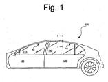
- a motor vehicle 100 comprises a window pane 110, a door 120 and a sealing profile 10.
- the sealing profile 10 is arranged on the upper side of the door 120 of the motor vehicle 100.
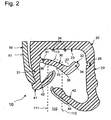
- the window pane 110 has a first side surface 111 (outer side surface), a second side surface 112 (inner side surface) and an end surface (upper side) 113.
- the nominal or structural position of the window pane 110 is shown in FIGS Fig. 2 and 3 shown in dashed lines.
- the sealing profile 10 is shown below with the aid of a section along the line II ( Fig. 1 ) explained in more detail.
- the sealing profile 10 is extruded from an ethylene-propylene-diene rubber and comprises a receiving section 20, a bottom lip 30, a first sealing lip 41, a second sealing lip 42 and a decorative element 50.
- the receiving section 20 comprises a first leg 21, a second leg 22 and a base 23.
- the two legs 21, 22 and the base 23 are arranged such that they form a substantially U-shaped cross section.
- the receiving section 20 receives the end face 113 and part of the window pane 110.
- the window pane 110 is then located between the two legs 21, 22.
- a cavity 26 is formed which is delimited by the bottom lip 30, the first leg 21, the base 23 and a support section 34 (described further below).
- the window pane 110 is completely outside of the receiving section 20.
- the first leg 21 has an area to which the decorative element 50 can be attached and an area to which the bottom lip 30 is arranged.
- the second leg 22 has a groove 25 arranged therein, which extends along the entire sealing profile 10. The groove 25 allows the second leg 22 to be bent so that the sealing profile 10 can be fastened to the door 120 in a corresponding receptacle (not shown).
- the base 23 has one end portion on which one end of the first leg 21 is arranged, and another end portion on which one end of the second leg 22 is arranged.
- the base 23 connects the two legs 21, 22 in this way.
- At least one projection 24 (here two projections), which projects from a lower surface of the base 23 in the direction of the bottom lip 30, is provided.
- the projections 24 prevent the bottom lip 30 from being pressed completely against the base 23 by the window pane 110. When the window pane 110 is opened, the bottom lip 30 moves without having to detach from the base 23. This avoids any undesirable noise associated with this release process.
- the bottom lip 30 comprises a first end 31, a second end 32, a contact surface 33, a support section 34, a first cam section 35, a second cam section 36 and a bulge 37.
- the first end 31 of the bottom lip 30 is on the first leg 22, for example arranged.
- the second end 32 of the bottom lip 30 is a free end, i. the second end 32 moves when the bottom lip is moved while the first end remains stationary except for articulation or rotation.
- the contact surface 33 is arranged between the first end 31 and the second end 32 and is concavely curved.
- the support portion 34 is in this Embodiment of the present invention formed by the second end 32, but can also be formed as an independent part.
- the first cam section 35 is arranged at the second end 32 of the bottom lip 30 and adjoins the contact surface 33. In the case of the first cam section 35, the bulge 37 is arranged on the side of the bottom lip 30 facing the base 23.
- the bottom lip 30 is therefore L-shaped in this embodiment.
- the second cam section 36 is located in the vicinity of the first end 31 and adjoins the first end 31 and the contact surface 33.
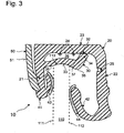
- the support section 34 is arranged at the second end 32 of the floor lip 30 and supports the floor lip 30 on the base 23 in the closed position. If the window pane 110 is in the closed position (see Fig. 3 ), the bottom lip 30 is pressed towards the base 23. Because the bottom lip 30 is supported by the support portion 34, it is also curved toward the base 23.
- the contact surface 33 is also curved concavely by the end surface 113 of the window pane 110. Due to the curvature of the contact surface 33, the first cam section 35 and the second cam section 36 turn around the end face 113 and lie against the two side faces 111, 112. The first cam section 35 and the second cam section 36 thus prevent the window pane 110 from moving in a direction perpendicular to a tangential plane of the side surface 111, 112. The window pane 110 is thus positively captured and stabilized and held in its nominal position.
- the cavity 26 is filled with air and supports the window pane 110 in a vibration-damped manner, since the bottom lip 30 can deform elastically in the event of vibrations of the window pane 110 and can absorb the movement of the window pane 110.
- the first sealing lip 41 with a first sealing section 43 and the second sealing lip 42 with a second sealing section 44 are each arranged on the first and second legs 21, 22 in this exemplary embodiment.
- the two sealing sections 43, 44 are formed by flocking.
- the two sealing lips 41, 42 are elastically deformed by the window pane 110. If a force now acts on the window pane 110, for example due to pressure fluctuations, the sealing lips 41, 42 can absorb this and the window pane 110 in keep their design position.
- the flocked sealing sections 43, 44 ensure a reliable seal.
- the decorative element 50 is made of aluminum and has a shiny surface 51.
- the decorative element 50 is attached to the first leg 21 by a clamp connection.
- the surface 51 is used for the pleasant aesthetic design of the sealing profile 10 for an external viewer of the motor vehicle 100.
- the sealing profile 10 reliably seals the interior of the vehicle from the surroundings of the vehicle, since the special shape of the floor lip 30 prevents the window pane 110 from moving in an inward or outward direction.
- the window pane 110 is stabilized and held in its construction position by means of the two sealing lips 41, 42. Due to the elasticity of the material and the cavity 26 formed in the closed position, the window pane 110 is also supported in a vibration-damped manner. Noises resulting from vibration of the window pane 110 can thus be avoided.
Landscapes
- Engineering & Computer Science (AREA)
- Mechanical Engineering (AREA)
- Seal Device For Vehicle (AREA)
- Specific Sealing Or Ventilating Devices For Doors And Windows (AREA)
Description
- Die Erfindung betrifft ein Dichtungsprofil für eine bewegbare Fensterscheibe eines Kraftfahrzeugs.
- Bewegbare Fensterscheiben befinden sich heutzutage in zahlreichen Kraftfahrzeugen. Die Abdichtung des Innenraums des Fahrzeugs gegenüber der Fahrzeugumgebung, insbesondere gegen Schall, Wärme/Kälte und Feuchtigkeit, in einer Schließstellung der Scheibe, ist hierbei von großer Bedeutung. Zusätzlich wird von einem Dichtungsprofil gefordert, dass es eine Fensterscheibe eines Kraftfahrzeugs schwingungsgedämpft lagert, so dass auch bei höheren Fahrgeschwindigkeiten keine unerwünschten Geräusche aufgrund einer Vibration der Fensterscheibe auftreten.
-
EP 1 935 694 B1 offenbart ein Dichtungsprofil zum Abdichten einer Kraftfahrzeugtür gegenüber einer Karosserie eines Kraftfahrzeugs. Hierzu sind mehrere Dichtlippen mit einer Beflockung und eine Bodenlippe, die eine Stirnfläche einer Fensterscheibe des Kraftfahrzeugs in der Schließstellung berührt, vorgesehen. In der Schließstellung liegen die Dichtlippen an den Seitenflächen der Fensterscheibe an, wodurch sie an einer seitlichen Bewegung durch die Dichtlippen gehindert wird. Die Bodenlippe hat eine konvex gekrümmte Kontaktfläche die die Stirnfläche der Fensterscheibe lediglich berührt, aber nicht stabil erfasst. Treten beispielsweise durch den Fahrtwind erzeugte Druckschwankungen auf, so wirkt eine Kraft oder wenigstens eine Kraftkomponente senkrecht zu einer Seitenfläche auf die Fensterscheibe. Diese Kraft muss von den Dichtlippen vollständig aufgenommen werden, um eine Bewegung und somit eine Vibration der Fensterscheibe zu verhindern und eine zuverlässige Abdichtung sicherzustellen. Die Rücktreibenden Kräfte der Dichtlippen, die aufgrund ihrer elastischen Verformung an der Fensterscheibe anliegen, reichen allgemein jedoch nicht aus, die Bewegung und somit eine Vibration der Fensterscheibe zu verhindern. Außerdem bietet die konvexe Kontaktfläche der Stirnfläche keinen Halt, so dass die Fensterscheibe entlang der Bodenlippe rutschen kann. Ein solches Dichtungsprofil ist daher nicht in der Lage eine zuverlässige Abdichtung zu gewährleisten und eine Vibration der Fensterscheibe, mit der unerwünschte Geräuschentwicklung einhergeht, zu verhindern. Ein solches Dichtungsprofil ist auch ausEP 2 222 491 B1 bekannt. - Ein Dichtungsprofil ohne Dichtlippen ist aus
EP 1 279 542 B1 bekannt. Hierbei wird ein Abschnitt des Dichtungsprofils von einer Fensterscheibe in einen Hohlraum gedrückt, so dass die Fensterscheibe in einer Schließstellung an ihren beiden Seitenflächen und an der Stirnfläche von diesem Abschnitt umgriffen und festgehalten wird. Aufgrund der in das Dichtungsprofil integrierten Hohlräume kann sich das Dichtungsprofil jedoch elastisch verformen, wobei die Fensterscheibe wieder in Bewegung gerät und Vibrationen und die damit einhergehende unerwünschte Geräuschentwicklung auftritt. - Eine weitere Möglichkeit, eine Fensterscheibe durch ein Dichtungsprofil abzudichten, ist aus
DE 102 00 809 A1 ersichtlich. Dieses Dichtungsprofil ist speziell für rahmenlose Türen, beispielsweise an einem Cabriolet, vorgesehen. Die Dichtlippe umgreift die Stirnfläche der Fensterscheibe. Da die Dichtlippe bei diesem Dichtungsprofil senkrecht zu einer Seitenfläche der Fensterscheibe bewegbar ist, kommt die Fensterscheibe in diesem Fall zusammen mit der Dichtlippe in Bewegung, was nicht nur zu unerwünschten Geräuschen führt, sondern in diesem Fall sogar noch zusätzliche sogenannte Schmatzgeräusche nach sich zieht. Diese entstehen beim Lösen zweier Oberflächen aus elastomerem Werkstoff, die zuvor aneinander gepresst worden sind. - Darüber hinaus offenbart
JP H08 318740 A - Aus
JP H06 55932 A -
JP 2010 52462 A - Eine bei einem Kraftfahrzeug Anwendung findende Dichtung, die einen Aufnahmeabschnitt, der im Querschnitt im Wesentlichen U-förmig ist, umfasst, wird in
GB 2 462 271 A - Weitere Dichtungen, die einen im Querschnitt U-förmigen Aufnahmeabschnitt aufweisen, werden in
WO 2006/042492 A1 ,DE 10 2008 053 870 A1 undDE 10 2009 053 937 A1 beschrieben. - Der Erfindung liegt die Aufgabe zugrunde, ein Dichtungsprofil für eine Fensterscheibe eines Kraftfahrzeugs zu schaffen, das eine zuverlässige Abdichtung ermöglicht und unerwünschte Geräusche, die mit einer Vibration der Fensterscheibe während der Fahrt einhergehen, verhindert.
- Der Erfindung liegt die Erkenntnis zugrunde, dass eine Bewegung der Fensterscheibe senkrecht zu einer Tangentialebene der Seitenflächen verhindert wird, wenn die Fensterscheibe in einer Nominal- oder Konstruktionslage stabilisiert wird. Ein Dichtungsprofil mit den Merkmalen des Anspruchs 1 macht diese Erkenntnis nutzbar. Vorteilhafte Ausgestaltungen der Erfindung sind Gegenstand der Ansprüche 2 bis 11.
- Ein Dichtungsprofil entsprechend einer Ausführungsform der Erfindung, ist für eine Fensterscheibe eines Kraftfahrzeugs, die zwischen einer Offenstellung und einer Schließstellung verschiebbar ist, und eine erste Seitenfläche, eine zweite Seitenfläche und eine Stirnfläche aufweist, gedacht. Das Dichtungsprofil hat einen Aufnahmeabschnitt, der im Querschnitt im Wesentlichen U-förmig ist sowie einen ersten Schenkel, einen zweiten Schenkel und eine Basis, die den ersten und zweiten Schenkel miteinander verbindet. Eine Bodenlippe, die ein erstes Ende hat, das an dem ersten Schenkel angeordnet ist, ein zweites Ende hat, das frei ist, und eine gekrümmte Kontaktfläche hat, die zwischen dem ersten und dem zweiten Ende angeordnet ist und die Stirnfläche der Fensterscheibe in der Schließstellung formschlüssig umgreift, ist in einem solchen Dichtungsprofil enthalten. Der Stützabschnitt, der zwischen der Bodenlippe und der Basis vorgesehen ist, dient dazu, die Bodenlippe in der Schließstellung an der Basis abzustützen. Dabei weist die Bodenlippe einen ersten Nockenabschnitt auf, der an die Kontaktfläche angrenzt und dazu dient, die Fensterscheibe am Bewegen in einer Richtung senkrecht zu einer Tangentialebene der Seitenfläche zu hindern.
- Bei einem solchen Dichtungsprofil ist die Fensterscheibe des Kraftfahrzeugs in der Schließstellung in dem Aufnahmeabschnitt aufgenommen. Die Bodenlippe wird durch den Stützabschnitt gegenüber der Basis abgestützt und durch die Fensterscheibe in Richtung der Basis gedrängt. Als Folge umgreift die Kontaktfläche die Fensterscheibe und der erste Nockenabschnitt erfasst die Fensterscheibe seitlich, wobei ein Formschluss zwischen der Bodenlippe und der Fensterscheibe entsteht. Die Fensterscheibe ist somit nicht mehr in der Lage, sich in eine Richtung senkrecht zu einer Tangentialebene einer Seitenfläche zu bewegen. Dadurch kann die Fensterscheibe zuverlässig abgedichtet und das entstehen von unerwünschten Geräuschen, die mit einer Vibration der Fensterscheibe einhergehen, verhindert werden. Bevorzugt ist der Stützabschnitt an der Basis angeordnet. Alternativ hierzu ist der Stützabschnitt an der Bodenlippe angeordnet. Vorzugsweise grenzt der Stützabschnitt auf der der Kontaktfläche abgewandten Seite an den ersten Nockenabschnitt.
- Durch die bevorzugte Anordnung des Stützabschnitts, wird der Formschluss verstärkt, da die Bodenlippe stärker in Richtung der Basis gedrängt und so stärker verkrümmt wird. Folglich umgreift die Kontaktfläche die Stirnfläche vollständig und der erste Nockenabschnitt wird an eine Seitenfläche der Scheibe anlegt. Der Nockenabschnitt hindert die Fensterscheibe an einer Bewegung, da die Fensterscheibe in der Nominal- oder Konstruktionslage zusätzlich stabilisiert ist. Auf diese Weise kann eine zuverlässige Abdichtung gewährleistet und das Entstehen unerwünschter Geräusche aufgrund einer Vibration der Fensterscheibe verhindert werden.
- Weiter bevorzugt ist die Kontaktfläche konkav gekrümmt. Durch die konkave Krümmung der Bodenlippe wird der Formschluss weiter verstärkt und die Fensterscheibe weiter in der Konstruktionslage stabilisiert.
- Erfindungsgemäßbegrenzen die Bodenlippe, die Basis, der erste Schenkel und der Stützabschnitt in der Schließstellung einen Hohlraum. Durch den Hohlraum ist die Bodenlippe in der Lage sich elastisch federnd zu bewegen und Vibrationen der Fensterscheibe aufzunehmen. Die Fensterscheibe ist dadurch zusätzlich schwingungsgedämpft gelagert.
- Bei einer weiteren bevorzugten Ausführungsform umfasst die Bodenlippe einen zweiten Nockenabschnitt, der an die Kontaktfläche angrenzt. Der zweite Nockenabschnitt ist vorzugsweise an dem, dem ersten Nockenabschnitt abgewandten, Ende der Bodenlippe angeordnet.
- Bei einem solchen Dichtungsprofil wird die Bewegung der Fensterscheibe auch in eine andere Richtung senkrecht zu einer Tangentialebene der Fensterscheibe verhindert. Die Fensterscheibe ist dadurch in einer Konstruktions- oder Nominallage stabilisiert. Folglich kann die Fensterscheibe zuverlässig Abgedichtet werden. Zusätzlich ist die Schwingungsdämpfung erheblich verbessert, wodurch unerwünschte Geräusche verhindert werden können.
- Vorzugsweise ist die Kontaktfläche aufgeraut, beschichtet oder aus einem Reibmaterial gefertigt, damit die Kontaktfläche die Stirnfläche der Fensterscheibe zusätzlich kraftschlüssig (reibschlüssig) erfasst. Eine Bewegung der Fensterscheibe wird durch den zusätzlichen Kraftschluss (Reibschluss) zusätzlich erschwert. Zusätzlich werden Vibrationen der Fensterscheibe besser von der Bodenlippe aufgenommen, was das Auftreten von unerwünschten Geräuschen verhindert.
- Das Dichtungsprofil umfasst besonders bevorzugt eine erste Dichtlippe, die an dem ersten Schenkel angeordnet ist, und eine zweite Dichtlippe, die an dem zweiten Schenkel angeordnet ist. Durch die beiden zusätzlichen Dichtlippen wird die Fensterscheibe an einer Bewegung senkrecht zu einer Tangentialebene ihrer Seitenfläche gehindert. Die Fensterscheibe wird dabei in der Konstruktionslage stabilisiert und das Entstehen von unerwünschten Geräuschen verhindert. Zusätzlich kann eine zuverlässige Abdichtung der Fensterscheibe gewährleistet werden.
- Es ist bevorzugt, dass die erste Dichtlippe einen, vorzugsweise reibungsmindernd ausgebildeten oder beflockten, ersten Dichtabschnitt, der an die erste Seitenfläche anlegbar ist, umfasst.
- Es ist bevorzugt, dass die zweite Dichtlippe einen, vorzugsweise reibungsmindernd ausgebildeten oder beflockten, zweiten Dichtabschnitt, der an die zweite Seitenfläche anlegbar ist, umfasst.
- Die Beflockung der Dichtabschnitte erlaubt es der Fensterscheibe leicht in den oder aus dem Aufnahmeabschnitt bei einer Schließ- oder Öffnungsbewegung zu gleiten. Außerdem wird die Fensterscheibe zuverlässig abgedichtet und durch den zusätzlichen Formschluss das Entstehen unerwünschter Geräusche verhindert.
- Erfindungsgemäßist wenigstens ein Vorsprung an der Basis angeordnet, der ein vollflächiges Anlegen der Bodenlippe an die Basis verhindert. Wenn die Bodenlippe durch die Fensterscheibe gegen die Basis gedrückt wird, können die Bodenlippe und die Basis aneinander haften. Beim Öffnen treten dann sogenannte Schmatzgeräusche auf, wenn sich die Bodenlippe wieder von der Basis löst. Der wenigstens eine Vorsprung verhindert ein großflächiges anlegen der Bodenlippe an die Basis und somit das Auftreten der Schmatzgeräusche.
- Bevorzugt ist das Dichtungsprofil aus einem Elastomer gefertigt. Es ist besonders bevorzugt, dass das Elastomer ist ein thermplastisches Elastomer oder alternativ ein Ethylen-Propylen-Dien-Kautschuk ist. Das Dichtungsprofil ist bevorzugt extrudiert.
- Weiter bevorzugt umfasst das Dichtungsprofil entsprechend der vorliegenden Erfindung ein Zierelement oder eine Zierleiste. Dabei ist das Zierelement vorzugsweise aus einem Metall, wie etwa Aluminium, oder alternativ aus einer Aluminiumlegierung gefertigt.
- Durch die bevorzugte Ausgestaltung des Dichtungsprofils wird die Fensterscheibe in der Nominal- oder Konstruktionslage stabilisiert. Dies führt zu einer zuverlässigen Abdichtung des Innenraums des Fahrzeugs gegenüber der Fahrzeugumgebung hinsichtlich Schall, Wärme und Feuchtigkeit unabhängig von der Fahrgeschwindigkeit des Fahrzeugs. Zusätzlich ist die Fensterscheibe schwingungsgedämpft gelagert, wodurch unerwünschte Geräusche während der Fahrt verhindert werden.
- Richtungsangaben in der Beschreibung, wie "innen", "außen", "rechts", "links", "vorne", "hinten", "oben" und "unten" beziehen sich auf die Sichtweise einer in dem Fahrzeug sitzenden Person mit Blick in Richtung auf die Windschutzscheibe.
- Ein Ausführungsbeispiel der Erfindung wird nachfolgend anhand der beigefügten Zeichnungen erläutert. Darin zeigen:
- Fig. 1
- eine seitliche Teilansicht eines Kraftfahrzeugs;
- Fig. 2
- einen Querschnitt eines Ausführungsbeispiels eines Dichtungsprofils mit einer Fensterscheibe (Nominallage gestrichelt) in einer Offenstellung; und
- Fig. 3
- einen Querschnitt des Ausführungsbeispiels des Dichtungsprofils mit der Fensterscheibe in einer Schließstellung (gestrichelt).
- Wie aus
Fig. 1 ersichtlich, umfasst ein Kraftfahrzeug 100 eine Fensterscheibe 110, eine Tür 120 und ein Dichtungsprofil 10. Das Dichtungsprofil 10 ist an der Oberseite der Tür 120 des Kraftfahrzeugs 100 angeordnet. - Wie aus den
Fig. 2 und3 ersichtlich, weist die Fensterscheibe 110 eine erste Seitenfläche 111 (äußere Seitenfläche), eine zweite Seitenfläche 112 (innere Seitenfläche) und eine Stirnfläche (Oberseite) 113 auf. Die Nominal- oder Konstruktionslage der Fensterscheibe 110 ist in denFig. 2 und3 gestrichelt dargestellt. Das Dichtungsprofil 10 wird im Folgenden unter Zuhilfenahme eines Schnitts entlang der Linie I-I (Fig. 1 ) näher erläutert. - Das Dichtungsprofil 10 ist aus einem Ethylen-Propylen-Dien-Kautschuk extrudiert und umfasst einen Aufnahmeabschnitt 20, eine Bodenlippe 30, eine erste Dichtlippe 41, eine zweite Dichtlippe 42 und ein Zierelement 50. Der Aufnahmeabschnitt 20 umfasst einen ersten Schenkel 21, einen zweiten Schenkel 22 und eine Basis 23. Die beiden Schenkel 21, 22 sowie die Basis 23 sind so angeordnet, dass sie einen im Wesentlichen U-förmigen Querschnitt bilden.
- In der Schließstellung nimmt der Aufnahmeabschnitt 20 die Stirnfläche 113 und einen Teil Fensterscheibe 110 in sich auf. Die Fensterscheibe 110 befindet sich dann zwischen den beiden Schenkeln 21, 22. Außerdem wird ein Hohlraum 26 gebildet, der von der Bodenlippe 30, dem ersten Schenkel 21, der Basis 23 und einem Stützabschnitt 34 (weiter unten beschrieben) begrenzt ist. In der Offenstellung befindet sich die Fensterscheibe 110 vollständig außerhalb des Aufnahmeabschnitts 20.
- Der erste Schenkel 21 hat einen Bereich, an dem das Zierelement 50 befestigt werden kann, und einen Bereich an dem die Bodenlippe 30 angeordnet ist. Der zweite Schenkel 22 weist eine darin angeordnete Nut 25 auf, die sich entlang des gesamten Dichtungsprofils 10 erstreckt. Die Nut 25 erlaubt ein Knicken des zweiten Schenkels 22, damit das Dichtungsprofil 10 in einer entsprechenden Aufnahme (nicht gezeigt) an der Tür 120 befestigt werden kann.
- Die Basis 23 hat einen Endabschnitt, an dem ein Ende des ersten Schenkels 21 angeordnet ist, und einen anderen Endabschnitt, an dem ein Ende des zweiten Schenkels 22 angeordnet ist. Die Basis 23 verbindet auf diese Weise die beiden Schenkel 21, 22. Wenigstens ein Vorsprung 24 (hier zwei Vorsprünge), der von einer unteren Fläche der Basis 23 in Richtung der Bodenlippe 30 vorspringt, ist vorgesehen. Die Vorsprünge 24 verhindern, dass die Bodenlippe 30 durch die Fensterscheibe 110 vollständig an die Basis 23 gedrückt wird. Beim Öffnen der Fensterscheibe 110 bewegt sich die Bodenlippe 30 ohne sich von der Basis 23 lösen zu müssen. Dadurch wird ein unerwünschtes Geräusch, das mit diesem Lösevorgang einhergeht, vermieden.
- Die Bodenlippe 30 umfasst ein erstes Ende 31, ein zweites Ende 32, eine Kontaktfläche 33, einen Stützabschnitt 34, einen ersten Nockenabschnitt 35, einen zweiten Nockenabschnitt 36 und eine Ausbauchung 37. Das erste Ende 31 der Bodenlippe 30 ist beispielsweise an dem ersten Schenkel 22 angeordnet. Das zweite Ende 32 der Bodenlippe 30 ist ein freies Ende, d.h. das zweite Ende 32 wird bewegt, wenn die Bodenlippe bewegt wird, während das erste Ende bis auf eine Gelenk- oder Drehbewegung stationär bleibt.
- Die Kontaktfläche 33 ist zwischen dem ersten Ende 31 und dem zweiten Ende 32 angeordnet und konkav gekrümmt. Der Stützabschnitt 34 wird bei diesem Ausführungsbeispiel der vorliegenden Erfindung von dem zweiten Ende 32 gebildet, kann aber auch als ein selbständiges Teil gebildet sein. Der erste Nockenabschnitt 35 ist an dem zweiten Ende 32 der Bodenlippe 30 angeordnet und grenzt an die Kontaktfläche 33. Bei dem ersten Nockenabschnitt 35 ist auf der, der Basis 23 zugewandten Seite der Bodenlippe 30 die Ausbauchung 37 angeordnet. Die Bodenlippe 30 ist daher bei diesem Ausführungsbeispiel L-förmig ausgebildet. Der zweite Nockenabschnitt 36 befindet sich in der Nähe des ersten Endes 31 und grenzt an das erste Ende 31 und die Kontaktfläche 33 an.
- Der Stützabschnitt 34 ist an dem zweiten Ende 32 der Bodenlippe 30 angeordnet und stützt in der Schließstellung die Bodenlippe 30 an der Basis 23 ab. Befindet sich die Fensterscheibe 110 in der Schließstellung (siehe
Fig. 3 ), ist die Bodenlippe 30 in Richtung der Basis 23 gedrückt. Weil die Bodenlippe 30 durch den Stützabschnitt 34 abgestützt ist, wird sie ebenso in Richtung der Basis 23 verkrümmt. Die Kontaktfläche 33 wird dabei von der Stirnfläche 113 der Fensterscheibe 110 ebenso konkav verkrümmt. Durch die Verkrümmung der Kontaktfläche 33 stülpen sich der erste Nockenabschnitt 35 und der zweite Nockenabschnitt 36 um die Stirnfläche 113 und liegen an den beiden Seitenflächen 111, 112 an. Der erste Nockenabschnitt 35 und der zweite Nockenabschnitt 36 verhindern so eine Bewegung der Fensterscheibe 110 in eine Richtung senkrecht zu einer Tangentialebene der Seitenfläche 111, 112. Die Fensterscheibe 110 wird somit formschlüssig erfasst und in ihrer Nominallage stabilisiert und gehalten. - Der Hohlraum 26 ist luftgefüllt und lagert die Fensterscheibe 110 schwingungsgedämpft, da sich die Bodenlippe 30 im Fall von Vibrationen der Fensterscheibe 110 elastisch verformen und die Bewegung der Fensterscheibe 110 aufnehmen kann. Die erste Dichtlippe 41 mit einem ersten Dichtabschnitt 43 und die zweite Dichtlippe 42 mit einem zweiten Dichtabschnitt 44 sind bei diesem Ausführungsbeispiel jeweils an dem ersten und zweiten Schenkel 21 ,22 angeordnet. Die beiden Dichtabschnitte 43, 44 sind dabei durch Beflocken gebildet.
- In der Schließstellung (
Fig. 3 ) werden die beiden Dichtlippen 41, 42 von der Fensterscheibe 110 elastisch verformt. Wenn nun eine Kraft auf die Fensterscheibe 110, beispielsweise aufgrund von Druckschwankungen, wirkt, können die Dichtlippen 41, 42 diese aufnehmen und die Fensterscheibe 110 in ihrer Konstruktionslage halten. Die beflockten Dichtabschnitte 43, 44 sorgen dabei für eine zuverlässige Abdichtung. - Das Zierelement 50 ist bei aus Aluminium und hat eine glänzende Oberfläche 51. Das Zierelement 50 ist an dem ersten Schenkel 21 durch eine Klemmverbindung befestigt. Die Oberfläche 51 dient der angenehmen ästhetischen Gestaltung des Dichtungsprofils 10 für einen äußeren Betrachter des Kraftfahrzeugs 100.
- Das Dichtungsprofil 10 dichtet den Innenraum des Fahrzeugs zuverlässig gegenüber der Umgebung des Fahrzeugs ab, da die spezielle Form der Bodenlippe 30 die Bewegung der Fensterscheibe 110 in eine Richtung nach innen oder außen verhindert. Die Fensterscheibe 110 wird zusätzlich zu dem Formschluss zwischen der Bodenlippe 30 und den Stirn- und Seitenflächen 111, 112, 113 mittel der beiden Dichtlippen 41, 42 in ihrer Konstruktionslage stabilisiert und gehalten. Durch die Elastizität des Werkstoffs und den in der Schließstellung gebildeten Hohlraum 26 ist die Fensterscheibe 110 auch schwingungsgedämpft gelagert. Von einer Vibration der Fensterscheibe 110 herrührende Geräusche können so vermieden werden.
-
- 10
- Dichtungsprofil
- 20
- Aufnahmeabschnitt
- 21
- erster Schenkel
- 22
- zweiter Schenkel
- 23
- Basis
- 24
- Vorsprung
- 25
- Nut
- 26
- Hohlraum
- 30
- Bodenlippe
- 31
- erstes Ende
- 32
- zweites Ende
- 33
- Kontaktfläche
- 34
- Stützabschnitt
- 35
- erster Nockenabschnitt
- 36
- zweiter Nockenabschnitt
- 37
- Ausbauchung
- 41
- erste Dichtlippe
- 42
- zweite Dichtlippe
- 43
- ersten Dichtabschnitt
- 44
- zweiten Dichtabschnitt
- 50
- Zierelement
- 51
- Oberfläche
- 100
- Kraftfahrzeug
- 110
- Fensterscheibe
- 111
- erste Seitenfläche
- 112
- zweite Seitenfläche
- 113
- Stirnfläche
- 120
- Tür
Claims (11)
- Dichtungsprofil (10) für eine Fensterscheibe (110) eines Kraftfahrzeugs (100), die zwischen einer Offenstellung und einer Schließstellung verschiebbar ist, und eine erste Seitenfläche (111), eine zweite Seitenfläche (112) und eine Stirnfläche (113) aufweist, umfassend:einen Aufnahmeabschnitt (20), der im Querschnitt im Wesentlichen U-förmig ist und einen ersten Schenkel (21), einen zweiten Schenkel (22) und eine den ersten und zweiten Schenkel (21, 22) miteinander verbindende Basis (23) aufweist;eine Bodenlippe (30), die ein erstes Ende (31), das an dem ersten Schenkel (21) angeordnet ist, und ein zweites Ende (32), das frei ist, aufweist, undeinen Stützabschnitt (34), der zwischen der Bodenlippe (30) und der Basis (23) vorgesehen und dazu ausgebildet ist, die Bodenlippe (30) in der Schließstellung an der Basis (23) abzustützen;dadurch gekennzeichnet, dass die Bodenlippe (30) eine gekrümmte Kontaktfläche (33), die zwischen dem ersten und dem zweiten Ende (31, 32) angeordnet ist und die Stirnfläche (113) der Fensterscheibe (110) in der Schließstellung formschlüssig umgreift, aufweist;wobei die Bodenlippe (30), die Basis (23), der erste Schenkel (21) und der Stützabschnitt (34) in der Schließstellung einen Hohlraum (26) begrenzen;wobei die Bodenlippe (30) einen ersten Nockenabschnitt (35) aufweist, der an die Kontaktfläche (33) angrenzt und dazu ausgebildet ist, die Fensterscheibe (110) am Bewegen in einer Richtung senkrecht zu einer Tangentialebene der Seitenfläche (111, 112) zu hindern,unddass wenigstens ein Vorsprung (24) vorgesehen ist, der an der Basis (23) angeordnet ist, um ein vollflächiges Anlegen der Bodenlippe (30) an die Basis (23) zu verhindern.
- Dichtungsprofil (10) nach Anspruch 1, dadurch gekennzeichnet, dass der Stützabschnitt (34) an der Basis (23) angeordnet ist.
- Dichtungsprofil (10) nach Anspruch 1, dadurch gekennzeichnet, dass der Stützabschnitt (34) an der Bodenlippe (30) angeordnet ist.
- Dichtungsprofil (10) nach Anspruch 3, dadurch gekennzeichnet, dass der Stützabschnitt (34) auf der der Kontaktfläche (33) abgewandten Seite an den ersten Nockenabschnitt (35) grenzt.
- Dichtungsprofil (10) nach einem der Ansprüche 1 bis 4, dadurch gekennzeichnet, dass die Kontaktfläche (33) konkav gekrümmt ist.
- Dichtungsprofil (10) nach einem der Ansprüche 1 bis 5, dadurch gekennzeichnet, dass die Bodenlippe (30) einen zweiten Nockenabschnitt (36) umfasst, der an die Kontaktfläche (33) angrenzt und an dem, dem ersten Nockenabschnitt (35) abgewandten Ende (31, 32) der Bodenlippe (30) angeordnet ist.
- Dichtungsprofil (10) nach einem der Ansprüche 1 bis 6, dadurch gekennzeichnet, dass die Kontaktfläche (33) aufgeraut oder beschichtet oder aus einem Reibmaterial gefertigt ist, um die Stirnfläche (113) der Fensterscheibe (110) zusätzlich kraftschlüssig zu halten.
- Dichtungsprofil (10) nach einem der Ansprüche 1 bis 7, gekennzeichnet durch eine erste Dichtlippe (41), die an dem ersten Schenkel (21) angeordnet ist, und eine zweite Dichtlippe (42), die an dem zweiten Schenkel (22) angeordnet ist.
- Dichtungsprofil (10) nach Anspruch 8, dadurch gekennzeichnet,
dass die erste Dichtlippe (41) einen, vorzugsweise reibungsmindernd ausgebildeten oder beflockten, ersten Dichtabschnitt (43), der an die erste Seitenfläche (111) anlegbar ist, umfasst, und/oder
dass die zweite Dichtlippe (42) einen, vorzugsweise reibungsmindernd ausgebildeten oder beflockten, zweiten Dichtabschnitt (44), der an die zweite Seitenfläche (112) anlegbar ist, umfasst. - Dichtungsprofil (10) nach einem der Ansprüche 1 bis 9, dadurch gekennzeichnet, dass das Dichtungsprofil (10) aus einem Elastomer, vorzugsweise einem thermoplastischen Elastomer oder einem Ethylen-Propylen-Dien-Kautschuk, gefertigt, vorzugsweise extrudiert, ist.
- Dichtungsprofil (10) nach einem der Ansprüche 1 bis 10, gekennzeichnet durch ein Zierelement (50), das an dem ersten oder zweiten Schenkel (21,22) angeordnet und vorzugsweise aus Metall, Aluminium oder einer Aluminiumlegierung gefertigt ist.
Priority Applications (1)
| Application Number | Priority Date | Filing Date | Title |
|---|---|---|---|
| PL13814538T PL2785547T3 (pl) | 2013-02-26 | 2013-12-19 | Profil uszczelniający |
Applications Claiming Priority (2)
| Application Number | Priority Date | Filing Date | Title |
|---|---|---|---|
| DE102013101896.3A DE102013101896A1 (de) | 2013-02-26 | 2013-02-26 | Dichtungsprofil |
| PCT/EP2013/077442 WO2014131480A1 (de) | 2013-02-26 | 2013-12-19 | Dichtungsprofil |
Publications (3)
| Publication Number | Publication Date |
|---|---|
| EP2785547A1 EP2785547A1 (de) | 2014-10-08 |
| EP2785547B1 EP2785547B1 (de) | 2015-07-08 |
| EP2785547B2 true EP2785547B2 (de) | 2020-09-23 |
Family
ID=49885256
Family Applications (1)
| Application Number | Title | Priority Date | Filing Date |
|---|---|---|---|
| EP13814538.8A Active EP2785547B2 (de) | 2013-02-26 | 2013-12-19 | Dichtungsprofil |
Country Status (7)
| Country | Link |
|---|---|
| US (1) | US9475372B2 (de) |
| EP (1) | EP2785547B2 (de) |
| CN (1) | CN104364106B (de) |
| DE (1) | DE102013101896A1 (de) |
| ES (1) | ES2546535T5 (de) |
| PL (1) | PL2785547T3 (de) |
| WO (1) | WO2014131480A1 (de) |
Families Citing this family (6)
| Publication number | Priority date | Publication date | Assignee | Title |
|---|---|---|---|---|
| DE102015010073B3 (de) * | 2015-08-03 | 2016-11-17 | Henniges Automotive Gmbh & Co. Kg | Scheibenanordnung, insbesondere Karosserie-Scheibenanordnung |
| DE102015013974A1 (de) | 2015-10-29 | 2017-05-04 | Henniges Automotive Gmbh & Co. Kg | Scheibenanordnung, insbesondere Karosserie-Scheibenanordnung |
| JP6781037B2 (ja) * | 2016-04-12 | 2020-11-04 | 西川ゴム工業株式会社 | 車両用ドアのグラスラン |
| US10710440B1 (en) | 2019-04-29 | 2020-07-14 | Toyota Motor Engineering & Manufacturing North America, Inc. | Glass run seal comprising corner moldings with integrated window spacers |
| CN112193040B (zh) * | 2020-10-08 | 2022-07-19 | 宁波阅荷思山智能科技有限公司 | 充气变形弯曲密封式无框车门汽车 |
| CN114889417A (zh) * | 2022-05-31 | 2022-08-12 | 瀚德(太仓)密封系统有限公司 | 一种无边框密封条 |
Family Cites Families (43)
| Publication number | Priority date | Publication date | Assignee | Title |
|---|---|---|---|---|
| DE2535508A1 (de) * | 1974-08-14 | 1976-02-26 | Nissan Motor | Fensterdichtung |
| GB2233377B (en) * | 1989-06-21 | 1993-08-25 | Draftex Ind Ltd | Sealing strips |
| DE4017813A1 (de) * | 1990-06-01 | 1991-12-05 | Metzeler Gmbh | Anordnung zur halterung eines fensterfuehrungsprofils |
| JPH0655932A (ja) * | 1992-08-12 | 1994-03-01 | Hino Motors Ltd | 自動車に使用されるドア・ガラスラン |
| DE4339033C2 (de) * | 1993-11-15 | 1997-08-21 | Metzeler Automotive Profiles | Anordnung zum gleichzeitigen Abdichten einer Türscheibe und der Türöffnung an einem Kraftfahrzeug |
| US5566510A (en) * | 1994-10-26 | 1996-10-22 | Gencorp Inc. | Molded glass run channel corner assembly |
| JP3312554B2 (ja) * | 1995-03-23 | 2002-08-12 | 豊田合成株式会社 | 自動車用ガラスラン |
| WO1997039907A1 (en) * | 1996-04-25 | 1997-10-30 | Draftex Industries Limited | Sealing, trimming or guiding strips |
| FR2775224B1 (fr) * | 1998-02-26 | 2000-06-23 | Btr Sealing Systems France | Nouveau profile d'etancheite pour encadrement de vitre coulissante, notamment de porte de vehicule automobile, et son procede de fabrication |
| US6205712B1 (en) * | 1998-07-29 | 2001-03-27 | Decoma Exterior Trim Inc. | Decorative molding assembly for a vehicle door frame |
| US6409251B1 (en) * | 1999-05-27 | 2002-06-25 | Schlegel Corporation | Glass run surround cap |
| US6493992B2 (en) * | 1999-11-30 | 2002-12-17 | Toyoda Gosei Co., Ltd. | Glass run and attachment structure therefor |
| JP3770120B2 (ja) * | 2000-10-27 | 2006-04-26 | 東海興業株式会社 | ガラスランチャンネル及びガラスランチャンネル組立体 |
| DE10136174A1 (de) | 2001-07-25 | 2003-02-20 | Daimler Chrysler Ag | Dichtungsprofil für einen Kraftwagen |
| DE10200809A1 (de) | 2002-01-11 | 2003-11-06 | Contitech Profile Gmbh | Dichtungsprofil für rahmenlose Fensterscheiben an Türen von Fahrzeugen |
| US6817651B2 (en) * | 2002-05-01 | 2004-11-16 | Schlegel Corporation | Modular vehicular window seal assembly |
| JP3739732B2 (ja) * | 2002-07-31 | 2006-01-25 | 東海興業株式会社 | 車両用窓縁モール |
| DE10239076B4 (de) * | 2002-08-26 | 2004-12-16 | Metzeler Automotive Profile Systems Gmbh | Dichtungsanordnung, insbesondere zum Abdichten einer an einem Kraftfahrzeug angeordneten Verkleidung |
| JP2006502048A (ja) * | 2002-10-02 | 2006-01-19 | ジーディーエックス・ノース・アメリカ・インコーポレーテッド | シーリング、トリミング又はガイディング・ストリップ |
| FR2863212B1 (fr) * | 2003-12-09 | 2006-02-24 | Hutchinson | Procede pour fabriquer un joint d'etancheite, en particulier une coulisse pour vitrage de vehicule a moteur, et joint ainsi fabrique |
| US7316097B2 (en) * | 2004-09-28 | 2008-01-08 | Tokai Kogyo Co., Ltd. | Glass run channel for vehicle and glass run channel assembly for vehicle |
| GB2419371A (en) * | 2004-10-20 | 2006-04-26 | Gdx Automotive Rehburg Gmbh & | Sealing, trimming or guiding strips |
| GB0423875D0 (en) * | 2004-10-27 | 2004-12-01 | Gdx North America Inc | Sealing or guiding assemblies and methods of making them |
| JP4475529B2 (ja) * | 2005-03-31 | 2010-06-09 | 豊田合成株式会社 | 自動車用ガラスラン |
| JP4375273B2 (ja) * | 2005-03-31 | 2009-12-02 | 豊田合成株式会社 | 自動車用ガラスラン |
| GB2432870A (en) * | 2005-11-18 | 2007-06-06 | Gdx North America Inc | Sealing assemblies and methods of making them |
| DE102006021190B4 (de) * | 2006-05-06 | 2008-08-14 | GM Global Technology Operations, Inc., Detroit | Dichtungsprofil |
| DE102006060390B3 (de) | 2006-12-20 | 2008-02-07 | Metzeler Automotive Profile Systems Gmbh | Dichtungsprofil, insbesondere zum Abdichten einer Tür gegenüber der Karosserie eines Kraftfahrzeugs |
| EP1944182B1 (de) * | 2007-01-12 | 2009-03-18 | Rainforest R&D Limited | Befestigungsleiste zur Verwendung mit einer Abdichtung zum Abdichten eines Fensters einer Fahrzeugtür |
| FR2913215B1 (fr) * | 2007-03-01 | 2011-07-29 | Hutchinson | Systeme d'etancheite pour ouvrant de porte d'un vehicule,son procede de fabrication et vehicule l'incorporant |
| US8840170B2 (en) * | 2007-06-29 | 2014-09-23 | Cooper-Standard Automotive Inc. | Inner garnish assembly module system |
| DE202008000372U1 (de) * | 2008-01-09 | 2008-03-13 | Meteor Gummiwerke K.H. Bädje GmbH & Co. KG | Dichtungsanordnung |
| DE102008027877A1 (de) * | 2008-06-11 | 2009-12-17 | Bayerische Motoren Werke Aktiengesellschaft | Dichtung für eine Tür eines Kraftfahrzeuges |
| GB2462271B (en) * | 2008-07-30 | 2012-07-11 | Nissan Motor Mfg Uk Ltd | Vehicle glass seal |
| US8166708B2 (en) * | 2008-07-30 | 2012-05-01 | Ellis Peter J | Integrated glass run and upper reveal with film |
| JP5163367B2 (ja) * | 2008-08-26 | 2013-03-13 | 豊田合成株式会社 | ガラスランの取付構造 |
| EP2168800A1 (de) * | 2008-09-26 | 2010-03-31 | HUTCHINSON GmbH | Eckteil für eine Fensterführung mit verborgenem Rahmen, diese Führung bildender Dichtungsstrang und Dichtungssystem damit |
| DE102008055942B4 (de) | 2008-11-05 | 2012-03-01 | Metzeler Automotive Profile Systems Gmbh | Verfahren zur Herstellung eines Dichtungsprofils für ein Kraftfahrzeug und ein solches Dichtungsprofil |
| DE102008060448A1 (de) * | 2008-12-04 | 2010-06-17 | CADEA-Gesellschaft für Anwendung und Realisierung computerunterstützter Systeme mbH | Scheibeneinfassung |
| DE102009053937A1 (de) * | 2009-11-19 | 2010-06-17 | Daimler Ag | Profil für eine zwischen einer Schließstellung und wenigstens einer Offenstellung bewegbare Scheibe |
| US8978306B2 (en) * | 2009-12-01 | 2015-03-17 | Guardian Industries Corp. | Vehicle seal system |
| JP5610308B2 (ja) * | 2011-09-27 | 2014-10-22 | 豊田合成株式会社 | ガラスラン |
| JP2013184627A (ja) * | 2012-03-09 | 2013-09-19 | Toyoda Gosei Co Ltd | ガラスラン |
-
2013
- 2013-02-26 DE DE102013101896.3A patent/DE102013101896A1/de not_active Withdrawn
- 2013-12-19 CN CN201380013457.XA patent/CN104364106B/zh active Active
- 2013-12-19 WO PCT/EP2013/077442 patent/WO2014131480A1/de not_active Ceased
- 2013-12-19 US US14/431,879 patent/US9475372B2/en active Active
- 2013-12-19 PL PL13814538T patent/PL2785547T3/pl unknown
- 2013-12-19 EP EP13814538.8A patent/EP2785547B2/de active Active
- 2013-12-19 ES ES13814538T patent/ES2546535T5/es active Active
Also Published As
| Publication number | Publication date |
|---|---|
| PL2785547T3 (pl) | 2015-12-31 |
| WO2014131480A1 (de) | 2014-09-04 |
| US20150239329A1 (en) | 2015-08-27 |
| ES2546535T5 (es) | 2021-06-18 |
| ES2546535T3 (es) | 2015-09-24 |
| EP2785547A1 (de) | 2014-10-08 |
| CN104364106A (zh) | 2015-02-18 |
| EP2785547B1 (de) | 2015-07-08 |
| US9475372B2 (en) | 2016-10-25 |
| DE102013101896A1 (de) | 2014-08-28 |
| CN104364106B (zh) | 2017-07-21 |
Similar Documents
| Publication | Publication Date | Title |
|---|---|---|
| EP2785547B1 (de) | Dichtungsprofil | |
| DE69107589T2 (de) | Dichtungsvorrichtung eines Fensteröffnungsrahmens für eine absenkbare oder feste Glasscheibe. | |
| EP1572482A1 (de) | Dichtungsanordnung, insbesondere zum abdichten von fensterscheiben eines kraftfahrzeugs | |
| DE2535508A1 (de) | Fensterdichtung | |
| EP3154805B1 (de) | Schiebetür | |
| WO2008110231A1 (de) | Dichtungsprofil und dieses einbeziehende dichtungsanordnung | |
| DE20321549U1 (de) | Dicht-, Trimm- oder Führungsleiste | |
| EP2188143B1 (de) | Abdeckleiste | |
| WO1997012775A1 (de) | Dichtungsanordnung für kraftfahrzeuge | |
| DE19926955B4 (de) | Stegkappe aus gummielastischem Material | |
| DE102018207892A1 (de) | Konfiguration einer Scheibenführungsschiene für ein Automobil | |
| DE102008005230A1 (de) | Klappe für Fahrzeuge | |
| EP3348761B1 (de) | Vorrichtung zur schwenkbaren befestigung eines türflügels an einer türzarge | |
| DE102019126860A1 (de) | Deckel zum Verschließen einer Öffnung in einer Fahrzeugkarosserie | |
| EP2383136B1 (de) | Dichtungseinrichtung für eine Fahrzeugtür | |
| EP2243650B1 (de) | Blendenanordnung für ein KFZ-Fenster | |
| EP3031646A1 (de) | Abdichtungsanordnung für eine fahrzeugscheibe | |
| EP1818203A1 (de) | Dichtungselement für eine Sichtscheibe | |
| EP1279791B1 (de) | Absenkbare Türdichtung | |
| EP2054252B1 (de) | Kraftfahrzeug mit hinteren seitenscheiben | |
| DE102006028051B4 (de) | Dichtungsanordnung für eine Fensterscheibe in einer Fahrzeugkarosserie | |
| DE102008041970B4 (de) | Dichtungsprofil für eine verschiebbare Fensterscheibe eines Kraftfahrzeugs | |
| DE102007059411A1 (de) | Dichtung zum Abdichten der Fensterscheibe eines Kraftfahrzeugs, Verstärkungsträger für eine solche Dichtung und Verfahren zum Herstellen der Dichtung | |
| DE102005059275B4 (de) | Verblendungsvorrichtung für Fahrzeugdachsysteme mit öffnungsfähigem Deckel | |
| EP2829453B1 (de) | Schienenfahrzeug mit Schiebetür |
Legal Events
| Date | Code | Title | Description |
|---|---|---|---|
| PUAI | Public reference made under article 153(3) epc to a published international application that has entered the european phase |
Free format text: ORIGINAL CODE: 0009012 |
|
| 17P | Request for examination filed |
Effective date: 20140606 |
|
| AK | Designated contracting states |
Kind code of ref document: A1 Designated state(s): AL AT BE BG CH CY CZ DE DK EE ES FI FR GB GR HR HU IE IS IT LI LT LU LV MC MK MT NL NO PL PT RO RS SE SI SK SM TR |
|
| GRAP | Despatch of communication of intention to grant a patent |
Free format text: ORIGINAL CODE: EPIDOSNIGR1 |
|
| GRAS | Grant fee paid |
Free format text: ORIGINAL CODE: EPIDOSNIGR3 |
|
| DAX | Request for extension of the european patent (deleted) | ||
| INTG | Intention to grant announced |
Effective date: 20150416 |
|
| GRAA | (expected) grant |
Free format text: ORIGINAL CODE: 0009210 |
|
| AK | Designated contracting states |
Kind code of ref document: B1 Designated state(s): AL AT BE BG CH CY CZ DE DK EE ES FI FR GB GR HR HU IE IS IT LI LT LU LV MC MK MT NL NO PL PT RO RS SE SI SK SM TR |
|
| REG | Reference to a national code |
Ref country code: GB Ref legal event code: FG4D Free format text: NOT ENGLISH |
|
| REG | Reference to a national code |
Ref country code: AT Ref legal event code: REF Ref document number: 735105 Country of ref document: AT Kind code of ref document: T Effective date: 20150715 Ref country code: CH Ref legal event code: EP |
|
| REG | Reference to a national code |
Ref country code: IE Ref legal event code: FG4D Free format text: LANGUAGE OF EP DOCUMENT: GERMAN |
|
| REG | Reference to a national code |
Ref country code: DE Ref legal event code: R096 Ref document number: 502013000861 Country of ref document: DE |
|
| REG | Reference to a national code |
Ref country code: ES Ref legal event code: FG2A Ref document number: 2546535 Country of ref document: ES Kind code of ref document: T3 Effective date: 20150924 |
|
| REG | Reference to a national code |
Ref country code: RO Ref legal event code: EPE |
|
| REG | Reference to a national code |
Ref country code: NL Ref legal event code: MP Effective date: 20150708 |
|
| REG | Reference to a national code |
Ref country code: FR Ref legal event code: PLFP Year of fee payment: 3 |
|
| REG | Reference to a national code |
Ref country code: LT Ref legal event code: MG4D |
|
| REG | Reference to a national code |
Ref country code: PL Ref legal event code: T3 |
|
| PG25 | Lapsed in a contracting state [announced via postgrant information from national office to epo] |
Ref country code: GR Free format text: LAPSE BECAUSE OF FAILURE TO SUBMIT A TRANSLATION OF THE DESCRIPTION OR TO PAY THE FEE WITHIN THE PRESCRIBED TIME-LIMIT Effective date: 20151009 Ref country code: FI Free format text: LAPSE BECAUSE OF FAILURE TO SUBMIT A TRANSLATION OF THE DESCRIPTION OR TO PAY THE FEE WITHIN THE PRESCRIBED TIME-LIMIT Effective date: 20150708 Ref country code: LV Free format text: LAPSE BECAUSE OF FAILURE TO SUBMIT A TRANSLATION OF THE DESCRIPTION OR TO PAY THE FEE WITHIN THE PRESCRIBED TIME-LIMIT Effective date: 20150708 Ref country code: LT Free format text: LAPSE BECAUSE OF FAILURE TO SUBMIT A TRANSLATION OF THE DESCRIPTION OR TO PAY THE FEE WITHIN THE PRESCRIBED TIME-LIMIT Effective date: 20150708 Ref country code: NO Free format text: LAPSE BECAUSE OF FAILURE TO SUBMIT A TRANSLATION OF THE DESCRIPTION OR TO PAY THE FEE WITHIN THE PRESCRIBED TIME-LIMIT Effective date: 20151008 |
|
| REG | Reference to a national code |
Ref country code: SK Ref legal event code: T3 Ref document number: E 19460 Country of ref document: SK |
|
| PG25 | Lapsed in a contracting state [announced via postgrant information from national office to epo] |
Ref country code: PT Free format text: LAPSE BECAUSE OF FAILURE TO SUBMIT A TRANSLATION OF THE DESCRIPTION OR TO PAY THE FEE WITHIN THE PRESCRIBED TIME-LIMIT Effective date: 20151109 Ref country code: SE Free format text: LAPSE BECAUSE OF FAILURE TO SUBMIT A TRANSLATION OF THE DESCRIPTION OR TO PAY THE FEE WITHIN THE PRESCRIBED TIME-LIMIT Effective date: 20150708 Ref country code: RS Free format text: LAPSE BECAUSE OF FAILURE TO SUBMIT A TRANSLATION OF THE DESCRIPTION OR TO PAY THE FEE WITHIN THE PRESCRIBED TIME-LIMIT Effective date: 20150708 Ref country code: HR Free format text: LAPSE BECAUSE OF FAILURE TO SUBMIT A TRANSLATION OF THE DESCRIPTION OR TO PAY THE FEE WITHIN THE PRESCRIBED TIME-LIMIT Effective date: 20150708 Ref country code: IS Free format text: LAPSE BECAUSE OF FAILURE TO SUBMIT A TRANSLATION OF THE DESCRIPTION OR TO PAY THE FEE WITHIN THE PRESCRIBED TIME-LIMIT Effective date: 20151108 |
|
| REG | Reference to a national code |
Ref country code: DE Ref legal event code: R026 Ref document number: 502013000861 Country of ref document: DE |
|
| PLBI | Opposition filed |
Free format text: ORIGINAL CODE: 0009260 |
|
| PG25 | Lapsed in a contracting state [announced via postgrant information from national office to epo] |
Ref country code: DK Free format text: LAPSE BECAUSE OF FAILURE TO SUBMIT A TRANSLATION OF THE DESCRIPTION OR TO PAY THE FEE WITHIN THE PRESCRIBED TIME-LIMIT Effective date: 20150708 Ref country code: EE Free format text: LAPSE BECAUSE OF FAILURE TO SUBMIT A TRANSLATION OF THE DESCRIPTION OR TO PAY THE FEE WITHIN THE PRESCRIBED TIME-LIMIT Effective date: 20150708 |
|
| PLAX | Notice of opposition and request to file observation + time limit sent |
Free format text: ORIGINAL CODE: EPIDOSNOBS2 |
|
| 26 | Opposition filed |
Opponent name: CQLT SAARGUMMI TECHNOLOGIES S.A.R.L. Effective date: 20160408 |
|
| PG25 | Lapsed in a contracting state [announced via postgrant information from national office to epo] |
Ref country code: BE Free format text: LAPSE BECAUSE OF NON-PAYMENT OF DUE FEES Effective date: 20151231 |
|
| PG25 | Lapsed in a contracting state [announced via postgrant information from national office to epo] |
Ref country code: LU Free format text: LAPSE BECAUSE OF FAILURE TO SUBMIT A TRANSLATION OF THE DESCRIPTION OR TO PAY THE FEE WITHIN THE PRESCRIBED TIME-LIMIT Effective date: 20151219 Ref country code: MC Free format text: LAPSE BECAUSE OF FAILURE TO SUBMIT A TRANSLATION OF THE DESCRIPTION OR TO PAY THE FEE WITHIN THE PRESCRIBED TIME-LIMIT Effective date: 20150708 |
|
| PLBB | Reply of patent proprietor to notice(s) of opposition received |
Free format text: ORIGINAL CODE: EPIDOSNOBS3 |
|
| PG25 | Lapsed in a contracting state [announced via postgrant information from national office to epo] |
Ref country code: SI Free format text: LAPSE BECAUSE OF FAILURE TO SUBMIT A TRANSLATION OF THE DESCRIPTION OR TO PAY THE FEE WITHIN THE PRESCRIBED TIME-LIMIT Effective date: 20150708 |
|
| REG | Reference to a national code |
Ref country code: IE Ref legal event code: MM4A |
|
| PG25 | Lapsed in a contracting state [announced via postgrant information from national office to epo] |
Ref country code: IE Free format text: LAPSE BECAUSE OF NON-PAYMENT OF DUE FEES Effective date: 20151219 |
|
| REG | Reference to a national code |
Ref country code: FR Ref legal event code: PLFP Year of fee payment: 4 |
|
| PGFP | Annual fee paid to national office [announced via postgrant information from national office to epo] |
Ref country code: CZ Payment date: 20161213 Year of fee payment: 4 Ref country code: SK Payment date: 20161214 Year of fee payment: 4 |
|
| PGFP | Annual fee paid to national office [announced via postgrant information from national office to epo] |
Ref country code: RO Payment date: 20161209 Year of fee payment: 4 Ref country code: PL Payment date: 20161209 Year of fee payment: 4 |
|
| PG25 | Lapsed in a contracting state [announced via postgrant information from national office to epo] |
Ref country code: BG Free format text: LAPSE BECAUSE OF FAILURE TO SUBMIT A TRANSLATION OF THE DESCRIPTION OR TO PAY THE FEE WITHIN THE PRESCRIBED TIME-LIMIT Effective date: 20150708 |
|
| PG25 | Lapsed in a contracting state [announced via postgrant information from national office to epo] |
Ref country code: HU Free format text: LAPSE BECAUSE OF FAILURE TO SUBMIT A TRANSLATION OF THE DESCRIPTION OR TO PAY THE FEE WITHIN THE PRESCRIBED TIME-LIMIT; INVALID AB INITIO Effective date: 20131219 Ref country code: CY Free format text: LAPSE BECAUSE OF FAILURE TO SUBMIT A TRANSLATION OF THE DESCRIPTION OR TO PAY THE FEE WITHIN THE PRESCRIBED TIME-LIMIT Effective date: 20150708 Ref country code: NL Free format text: LAPSE BECAUSE OF FAILURE TO SUBMIT A TRANSLATION OF THE DESCRIPTION OR TO PAY THE FEE WITHIN THE PRESCRIBED TIME-LIMIT Effective date: 20150708 |
|
| REG | Reference to a national code |
Ref country code: CH Ref legal event code: PL |
|
| PG25 | Lapsed in a contracting state [announced via postgrant information from national office to epo] |
Ref country code: MT Free format text: LAPSE BECAUSE OF FAILURE TO SUBMIT A TRANSLATION OF THE DESCRIPTION OR TO PAY THE FEE WITHIN THE PRESCRIBED TIME-LIMIT Effective date: 20150708 |
|
| PG25 | Lapsed in a contracting state [announced via postgrant information from national office to epo] |
Ref country code: LI Free format text: LAPSE BECAUSE OF NON-PAYMENT OF DUE FEES Effective date: 20161231 Ref country code: CH Free format text: LAPSE BECAUSE OF NON-PAYMENT OF DUE FEES Effective date: 20161231 |
|
| REG | Reference to a national code |
Ref country code: FR Ref legal event code: PLFP Year of fee payment: 5 |
|
| PG25 | Lapsed in a contracting state [announced via postgrant information from national office to epo] |
Ref country code: SM Free format text: LAPSE BECAUSE OF FAILURE TO SUBMIT A TRANSLATION OF THE DESCRIPTION OR TO PAY THE FEE WITHIN THE PRESCRIBED TIME-LIMIT Effective date: 20150708 |
|
| RIC2 | Information provided on ipc code assigned after grant |
Ipc: B60J 10/50 20160101AFI20180522BHEP Ipc: B60J 10/763 20160101ALI20180522BHEP Ipc: B60J 10/74 20160101ALI20180522BHEP Ipc: B60J 10/27 20160101ALI20180522BHEP |
|
| PG25 | Lapsed in a contracting state [announced via postgrant information from national office to epo] |
Ref country code: MK Free format text: LAPSE BECAUSE OF FAILURE TO SUBMIT A TRANSLATION OF THE DESCRIPTION OR TO PAY THE FEE WITHIN THE PRESCRIBED TIME-LIMIT Effective date: 20150708 |
|
| PG25 | Lapsed in a contracting state [announced via postgrant information from national office to epo] |
Ref country code: CZ Free format text: LAPSE BECAUSE OF NON-PAYMENT OF DUE FEES Effective date: 20171219 |
|
| PG25 | Lapsed in a contracting state [announced via postgrant information from national office to epo] |
Ref country code: RO Free format text: LAPSE BECAUSE OF NON-PAYMENT OF DUE FEES Effective date: 20171219 |
|
| REG | Reference to a national code |
Ref country code: SK Ref legal event code: MM4A Ref document number: E 19460 Country of ref document: SK Effective date: 20171219 |
|
| PG25 | Lapsed in a contracting state [announced via postgrant information from national office to epo] |
Ref country code: AL Free format text: LAPSE BECAUSE OF FAILURE TO SUBMIT A TRANSLATION OF THE DESCRIPTION OR TO PAY THE FEE WITHIN THE PRESCRIBED TIME-LIMIT Effective date: 20150708 |
|
| PG25 | Lapsed in a contracting state [announced via postgrant information from national office to epo] |
Ref country code: SK Free format text: LAPSE BECAUSE OF NON-PAYMENT OF DUE FEES Effective date: 20171219 |
|
| APAH | Appeal reference modified |
Free format text: ORIGINAL CODE: EPIDOSCREFNO |
|
| APBM | Appeal reference recorded |
Free format text: ORIGINAL CODE: EPIDOSNREFNO |
|
| APBP | Date of receipt of notice of appeal recorded |
Free format text: ORIGINAL CODE: EPIDOSNNOA2O |
|
| APBM | Appeal reference recorded |
Free format text: ORIGINAL CODE: EPIDOSNREFNO |
|
| APBP | Date of receipt of notice of appeal recorded |
Free format text: ORIGINAL CODE: EPIDOSNNOA2O |
|
| APBQ | Date of receipt of statement of grounds of appeal recorded |
Free format text: ORIGINAL CODE: EPIDOSNNOA3O |
|
| RIC2 | Information provided on ipc code assigned after grant |
Ipc: B60J 10/74 20160101ALI20180522BHEP Ipc: B60J 10/50 20160101AFI20180522BHEP Ipc: B60J 10/27 20160101ALI20180522BHEP Ipc: B60J 10/763 20160101ALI20180522BHEP |
|
| APBQ | Date of receipt of statement of grounds of appeal recorded |
Free format text: ORIGINAL CODE: EPIDOSNNOA3O |
|
| PG25 | Lapsed in a contracting state [announced via postgrant information from national office to epo] |
Ref country code: PL Free format text: LAPSE BECAUSE OF NON-PAYMENT OF DUE FEES Effective date: 20171219 |
|
| REG | Reference to a national code |
Ref country code: AT Ref legal event code: MM01 Ref document number: 735105 Country of ref document: AT Kind code of ref document: T Effective date: 20181219 |
|
| PG25 | Lapsed in a contracting state [announced via postgrant information from national office to epo] |
Ref country code: AT Free format text: LAPSE BECAUSE OF NON-PAYMENT OF DUE FEES Effective date: 20181219 |
|
| APBU | Appeal procedure closed |
Free format text: ORIGINAL CODE: EPIDOSNNOA9O |
|
| REG | Reference to a national code |
Ref country code: DE Ref legal event code: R081 Ref document number: 502013000861 Country of ref document: DE Owner name: BAYERISCHE MOTOREN WERKE AKTIENGESELLSCHAFT, DE Free format text: FORMER OWNER: COOPER STANDARD GMBH, 88131 LINDAU, DE Ref country code: DE Ref legal event code: R081 Ref document number: 502013000861 Country of ref document: DE Owner name: COOPER STANDARD GMBH, DE Free format text: FORMER OWNER: COOPER STANDARD GMBH, 88131 LINDAU, DE Ref country code: DE Ref legal event code: R082 Ref document number: 502013000861 Country of ref document: DE Representative=s name: FLUEGEL PREISSNER SCHOBER SEIDEL PATENTANWAELT, DE |
|
| PUAH | Patent maintained in amended form |
Free format text: ORIGINAL CODE: 0009272 |
|
| STAA | Information on the status of an ep patent application or granted ep patent |
Free format text: STATUS: PATENT MAINTAINED AS AMENDED |
|
| 27A | Patent maintained in amended form |
Effective date: 20200923 |
|
| AK | Designated contracting states |
Kind code of ref document: B2 Designated state(s): AL AT BE BG CH CY CZ DE DK EE ES FI FR GB GR HR HU IE IS IT LI LT LU LV MC MK MT NL NO PL PT RO RS SE SI SK SM TR |
|
| REG | Reference to a national code |
Ref country code: DE Ref legal event code: R102 Ref document number: 502013000861 Country of ref document: DE |
|
| REG | Reference to a national code |
Ref country code: ES Ref legal event code: DC2A Ref document number: 2546535 Country of ref document: ES Kind code of ref document: T5 Effective date: 20210618 |
|
| PGFP | Annual fee paid to national office [announced via postgrant information from national office to epo] |
Ref country code: FR Payment date: 20211220 Year of fee payment: 9 Ref country code: GB Payment date: 20211222 Year of fee payment: 9 |
|
| PGFP | Annual fee paid to national office [announced via postgrant information from national office to epo] |
Ref country code: IT Payment date: 20211230 Year of fee payment: 9 Ref country code: ES Payment date: 20220119 Year of fee payment: 9 |
|
| PG25 | Lapsed in a contracting state [announced via postgrant information from national office to epo] |
Ref country code: TR Free format text: LAPSE BECAUSE OF NON-PAYMENT OF DUE FEES Effective date: 20171219 |
|
| GBPC | Gb: european patent ceased through non-payment of renewal fee |
Effective date: 20221219 |
|
| PG25 | Lapsed in a contracting state [announced via postgrant information from national office to epo] |
Ref country code: GB Free format text: LAPSE BECAUSE OF NON-PAYMENT OF DUE FEES Effective date: 20221219 |
|
| PG25 | Lapsed in a contracting state [announced via postgrant information from national office to epo] |
Ref country code: FR Free format text: LAPSE BECAUSE OF NON-PAYMENT OF DUE FEES Effective date: 20221231 |
|
| PG25 | Lapsed in a contracting state [announced via postgrant information from national office to epo] |
Ref country code: IT Free format text: LAPSE BECAUSE OF NON-PAYMENT OF DUE FEES Effective date: 20221219 |
|
| REG | Reference to a national code |
Ref country code: ES Ref legal event code: FD2A Effective date: 20240202 |
|
| PG25 | Lapsed in a contracting state [announced via postgrant information from national office to epo] |
Ref country code: ES Free format text: LAPSE BECAUSE OF NON-PAYMENT OF DUE FEES Effective date: 20221220 |
|
| PG25 | Lapsed in a contracting state [announced via postgrant information from national office to epo] |
Ref country code: ES Free format text: LAPSE BECAUSE OF NON-PAYMENT OF DUE FEES Effective date: 20221220 |
|
| PGFP | Annual fee paid to national office [announced via postgrant information from national office to epo] |
Ref country code: DE Payment date: 20260114 Year of fee payment: 13 |