EP2774706B1 - Schneideeinsatz, schneidewerkzeug sowie herstellungsverfahren für ein schneideprodukt mit dem schneidewerkzeug - Google Patents
Schneideeinsatz, schneidewerkzeug sowie herstellungsverfahren für ein schneideprodukt mit dem schneidewerkzeug Download PDFInfo
- Publication number
- EP2774706B1 EP2774706B1 EP12845789.2A EP12845789A EP2774706B1 EP 2774706 B1 EP2774706 B1 EP 2774706B1 EP 12845789 A EP12845789 A EP 12845789A EP 2774706 B1 EP2774706 B1 EP 2774706B1
- Authority
- EP
- European Patent Office
- Prior art keywords
- cutting edge
- rake
- cutting
- insert
- angle
- Prior art date
- Legal status (The legal status is an assumption and is not a legal conclusion. Google has not performed a legal analysis and makes no representation as to the accuracy of the status listed.)
- Active
Links
- 238000005520 cutting process Methods 0.000 title claims description 326
- 238000000034 method Methods 0.000 title claims description 13
- 238000004519 manufacturing process Methods 0.000 title 1
- 230000003247 decreasing effect Effects 0.000 claims description 6
- 230000002787 reinforcement Effects 0.000 description 24
- 230000001154 acute effect Effects 0.000 description 4
- 230000001747 exhibiting effect Effects 0.000 description 4
- 239000000463 material Substances 0.000 description 4
- 230000009467 reduction Effects 0.000 description 4
- 238000003801 milling Methods 0.000 description 3
- 230000004048 modification Effects 0.000 description 3
- 238000012986 modification Methods 0.000 description 3
- 230000002093 peripheral effect Effects 0.000 description 3
- 230000009471 action Effects 0.000 description 2
- 230000000694 effects Effects 0.000 description 2
- ATJFFYVFTNAWJD-UHFFFAOYSA-N Tin Chemical compound [Sn] ATJFFYVFTNAWJD-UHFFFAOYSA-N 0.000 description 1
- PNEYBMLMFCGWSK-UHFFFAOYSA-N aluminium oxide Inorganic materials [O-2].[O-2].[O-2].[Al+3].[Al+3] PNEYBMLMFCGWSK-UHFFFAOYSA-N 0.000 description 1
- 230000008901 benefit Effects 0.000 description 1
- -1 cemented carbide Substances 0.000 description 1
- 239000000919 ceramic Substances 0.000 description 1
- 239000011195 cermet Substances 0.000 description 1
- 230000008859 change Effects 0.000 description 1
- 239000011248 coating agent Substances 0.000 description 1
- 239000011247 coating layer Substances 0.000 description 1
- 238000000576 coating method Methods 0.000 description 1
- 229910052593 corundum Inorganic materials 0.000 description 1
- 230000001419 dependent effect Effects 0.000 description 1
- 230000006866 deterioration Effects 0.000 description 1
- 230000006872 improvement Effects 0.000 description 1
- 238000003754 machining Methods 0.000 description 1
- 230000014759 maintenance of location Effects 0.000 description 1
- 238000000465 moulding Methods 0.000 description 1
- 230000008569 process Effects 0.000 description 1
- 230000000717 retained effect Effects 0.000 description 1
- 230000003746 surface roughness Effects 0.000 description 1
- 229910001845 yogo sapphire Inorganic materials 0.000 description 1
Images


Classifications
-
- B—PERFORMING OPERATIONS; TRANSPORTING
- B23—MACHINE TOOLS; METAL-WORKING NOT OTHERWISE PROVIDED FOR
- B23C—MILLING
- B23C5/00—Milling-cutters
- B23C5/02—Milling-cutters characterised by the shape of the cutter
- B23C5/10—Shank-type cutters, i.e. with an integral shaft
- B23C5/109—Shank-type cutters, i.e. with an integral shaft with removable cutting inserts
-
- B—PERFORMING OPERATIONS; TRANSPORTING
- B23—MACHINE TOOLS; METAL-WORKING NOT OTHERWISE PROVIDED FOR
- B23C—MILLING
- B23C5/00—Milling-cutters
- B23C5/02—Milling-cutters characterised by the shape of the cutter
- B23C5/06—Face-milling cutters, i.e. having only or primarily a substantially flat cutting surface
-
- B—PERFORMING OPERATIONS; TRANSPORTING
- B23—MACHINE TOOLS; METAL-WORKING NOT OTHERWISE PROVIDED FOR
- B23C—MILLING
- B23C5/00—Milling-cutters
- B23C5/16—Milling-cutters characterised by physical features other than shape
- B23C5/20—Milling-cutters characterised by physical features other than shape with removable cutter bits or teeth or cutting inserts
- B23C5/202—Plate-like cutting inserts with special form
-
- B—PERFORMING OPERATIONS; TRANSPORTING
- B23—MACHINE TOOLS; METAL-WORKING NOT OTHERWISE PROVIDED FOR
- B23C—MILLING
- B23C2200/00—Details of milling cutting inserts
- B23C2200/04—Overall shape
- B23C2200/0494—Rectangular
-
- B—PERFORMING OPERATIONS; TRANSPORTING
- B23—MACHINE TOOLS; METAL-WORKING NOT OTHERWISE PROVIDED FOR
- B23C—MILLING
- B23C2200/00—Details of milling cutting inserts
- B23C2200/08—Rake or top surfaces
- B23C2200/085—Rake or top surfaces discontinuous
-
- B—PERFORMING OPERATIONS; TRANSPORTING
- B23—MACHINE TOOLS; METAL-WORKING NOT OTHERWISE PROVIDED FOR
- B23C—MILLING
- B23C2200/00—Details of milling cutting inserts
- B23C2200/12—Side or flank surfaces
- B23C2200/125—Side or flank surfaces discontinuous
-
- B—PERFORMING OPERATIONS; TRANSPORTING
- B23—MACHINE TOOLS; METAL-WORKING NOT OTHERWISE PROVIDED FOR
- B23C—MILLING
- B23C2200/00—Details of milling cutting inserts
- B23C2200/28—Angles
- B23C2200/284—Negative clearance angles
-
- B—PERFORMING OPERATIONS; TRANSPORTING
- B23—MACHINE TOOLS; METAL-WORKING NOT OTHERWISE PROVIDED FOR
- B23C—MILLING
- B23C2210/00—Details of milling cutters
- B23C2210/04—Angles
- B23C2210/0407—Cutting angles
- B23C2210/0442—Cutting angles positive
- B23C2210/045—Cutting angles positive axial rake angle
-
- B—PERFORMING OPERATIONS; TRANSPORTING
- B23—MACHINE TOOLS; METAL-WORKING NOT OTHERWISE PROVIDED FOR
- B23C—MILLING
- B23C2210/00—Details of milling cutters
- B23C2210/04—Angles
- B23C2210/0407—Cutting angles
- B23C2210/0442—Cutting angles positive
- B23C2210/0457—Cutting angles positive radial rake angle
-
- Y—GENERAL TAGGING OF NEW TECHNOLOGICAL DEVELOPMENTS; GENERAL TAGGING OF CROSS-SECTIONAL TECHNOLOGIES SPANNING OVER SEVERAL SECTIONS OF THE IPC; TECHNICAL SUBJECTS COVERED BY FORMER USPC CROSS-REFERENCE ART COLLECTIONS [XRACs] AND DIGESTS
- Y10—TECHNICAL SUBJECTS COVERED BY FORMER USPC
- Y10T—TECHNICAL SUBJECTS COVERED BY FORMER US CLASSIFICATION
- Y10T407/00—Cutters, for shaping
- Y10T407/22—Cutters, for shaping including holder having seat for inserted tool
-
- Y—GENERAL TAGGING OF NEW TECHNOLOGICAL DEVELOPMENTS; GENERAL TAGGING OF CROSS-SECTIONAL TECHNOLOGIES SPANNING OVER SEVERAL SECTIONS OF THE IPC; TECHNICAL SUBJECTS COVERED BY FORMER USPC CROSS-REFERENCE ART COLLECTIONS [XRACs] AND DIGESTS
- Y10—TECHNICAL SUBJECTS COVERED BY FORMER USPC
- Y10T—TECHNICAL SUBJECTS COVERED BY FORMER US CLASSIFICATION
- Y10T407/00—Cutters, for shaping
- Y10T407/23—Cutters, for shaping including tool having plural alternatively usable cutting edges
-
- Y—GENERAL TAGGING OF NEW TECHNOLOGICAL DEVELOPMENTS; GENERAL TAGGING OF CROSS-SECTIONAL TECHNOLOGIES SPANNING OVER SEVERAL SECTIONS OF THE IPC; TECHNICAL SUBJECTS COVERED BY FORMER USPC CROSS-REFERENCE ART COLLECTIONS [XRACs] AND DIGESTS
- Y10—TECHNICAL SUBJECTS COVERED BY FORMER USPC
- Y10T—TECHNICAL SUBJECTS COVERED BY FORMER US CLASSIFICATION
- Y10T83/00—Cutting
- Y10T83/04—Processes
Definitions
- the present invention relates to a cutting insert, a cutting tool, and a method of producing a machined product using the same.
- an upper cutting edge includes, sequentially from a first corner to a second corner, a corner cutting edge, a minor cutting edge inclined as separating from the corner cutting edge at a first inclination angle on a basis of a vertical plane perpendicular to a central axis extending between upper and lower surfaces, and a major cutting edge inclined as separating from the minor cutting edge at a second inclination angle on the basis of the vertical plane so as to become more closer to the lower surface than the minor cutting edge.
- a cross section of a rake surface obtained by cutting an inwardly located end portion thereof along a direction of the central axis has a straight line shape or concave shape in a region crossing over at least a minor rake surface and a major rake surface.
- WO 2011/052340 A1 shows a cutting insert with the features of the preamble of claim 1.
- An object of the present invention is to provide a cutting insert and a cutting tool each having the excellent chip discharge performance, as well as a method of producing a machined product using the cutting insert and the cutting tool.
- the present invention provides a cutting insert as defined in claim 1 and a cutting tool as defined in claim 14, as well as a method of producing a machined product as defined in claim 15. Further embodiments of the cutting insert of the present invention are described in dependent claims 2 to 13.
- a cutting insert includes an upper surface, a lower surface, a side surface that is connected to each of the upper surface and the lower surface, and sequentially includes a first side surface, a corner side surface, and a second side surface, and a cutting edge.
- the cutting edge includes a major cutting edge located at an intersecting part of the upper surface and the first side surface, a corner cutting edge located at an intersecting part of the upper surface and the corner side surface, and a minor cutting edge located at an intersecting part of the upper surface and the second side surface.
- the upper surface sequentially includes a first rake surface and a second rake surface.
- the first rake surface is located along the cutting edge and is inclined toward the lower surface as going inward from the cutting edge at a first rake angle on a basis of a perpendicular plane perpendicular to a central axis extending between the upper surface and the lower surface.
- the second rake surface is located more inward than the first rake surface and is inclined toward the lower surface at a second rake angle different from the first rake angle on the basis of the perpendicular plane.
- An intersecting part of the first rake surface and the second rake surface includes a protruded part located at a highest position in a region of the intersecting part extending along the second side surface.
- a cutting tool includes the cutting insert of the foregoing embodiment, and a holder configured to attach the cutting insert to the holder.
- a method of producing a machined product according to an embodiment of the present invention includes rotating the cutting tool according to the foregoing embodiment, bringing the cutting edge of the cutting tool being rotated into contact with a workpiece, and separating the cutting tool from the workpiece.
- the upper surface sequentially includes the first rake surface and the second rake surface.
- the first rake surface is located along the cutting edge and is inclined toward the lower surface as going inward from the cutting edge at the first rake angle on the basis of the perpendicular plane perpendicular to the central axis extending between the upper surface and the lower surface.
- the second rake surface is located more inward than the first rake surface and is inclined toward the lower surface at the second rake angle different from the first rake angle on the basis of the perpendicular plane.
- the intersecting part of the first rake surface and the second rake surface includes the protruded part located at the highest position in the region of the intersecting part extending along the second side surface. Therefore, even under the cutting conditions that the corner cutting edge and the minor cutting edge are used mainly and the depth of cut is relatively small, generated chips can be stably curled by the high protruded part located in the region of the intersecting part extending along the second side surface, thereby exhibiting the excellent chip discharge performance.
- a cutting insert (hereinafter generally referred to as an "insert") according to an embodiment of the present invention is described in detail below with reference to Figs. 1 to 7 .
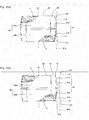
- the insert 1 of the present embodiment generally includes an upper surface 2, a lower surface 3, a side surface 4 connected to each of the upper surface 2 and the lower surface 3, a through hole 6 extending between the upper surface 2 and the lower surface 3, and a cutting edge 5 located at an intersecting part of the upper surface 2 and the side surface 4.
- the upper surface 2 includes a rake surface 8 and a flat surface 21.
- the side surface 4 includes a first side surface 41, a corner side surface 43, and a second side surface 42.
- the cutting edge 5 includes a major cutting edge 51, a corner cutting edge 53, and a minor cutting edge 52.
- the insert 1 has an approximately quadrangular shape (approximately rectangular shape) in a top view.
- top view denotes a condition in which the insert 1 is viewed from the upper surface 2.
- the shape of the insert 1 is not limited to the approximately quadrangular shape.
- the insert 1 may have a plate shape of an approximately polygonal shape, such as triangle, pentagon, hexagon, and octagon, in the top view.
- the insert 1 may be configured so that each long side of the approximately quadrangular shape measures approximately 8-15 mm and each short side thereof measures approximately 4-8 mm in the top view.
- a thickness from the upper surface 2 to the lower surface 3 may be approximately 3-7 mm.
- the term "thickness” denotes a line segment parallel to a central axis S1 of the insert 1 in a distance from a portion of the upper surface 2 that is located uppermost to a portion of the lower surface 3 that is located lowermost in a side view.
- side view denotes a condition in which the insert 1 is viewed toward the first side surface 41.
- the term "central axis S1 of the insert 1” denotes the axis that extends between the upper surface 2 and the lower surface 3, and serves as a rotation axis when the insert 1 is rotated in the top view.
- the insert 1 also includes a cutting edge 5A having a major cutting edge 51A and a minor cutting edge 52A, at an intersecting part of the lower surface 3 and the side surface 4.
- the flat surface 21 of the upper surface 2 is usable as a seating surface to a holder 10 described later. That is, with the insert 1 of the present embodiment, the upper surface 2 and the lower surface 3 are individually usable for the cutting process. Therefore, in order to ensure the use of the insert 1 in a vertically inverted state, the major cutting edge 51A close to the lower surface 3 has a shape obtained by inverting the major cutting edge 51 close to the upper surface 2.
- the insert 1 has rotational symmetry around a line normal to the paper surface of Fig. 1(c) .
- the cutting process is performable using a total of four corners, namely, two on each of the upper surface 2 and the lower surface 3.
- a portion of the side surface 4 configured to dispose the major cutting edge 51 and a portion of the side surface 4 configured to dispose the minor cutting edge 52 are respectively independently configured as the first side surface 41 and the second side surface 42.
- This configuration makes it relatively easy to design a suitable configuration for the major cutting edge 51 and the rake surface 8 located on the upper surface 2 along the major cutting edge 51, and a suitable configuration for a flank surface (a second upper constraining surface 42a) with respect to the minor cutting edge 52.
- the individual components of the insert 1 according to the present embodiment are described in further detail below.
- the cutting edge 5 is the located at the intersecting part of the upper surface 2 and the side surface 4, and includes the major cutting edge 51 and the minor cutting edge 52.
- the major cutting edge 51 and the minor cutting edge 52 are connected to each other with the corner cutting edge 53 interposed therebetween as shown in Fig. 1(b) .
- the insert 1 of the present embodiment is capable of performing the cutting process by using a corner including the major cutting edge 51, the minor cutting edge 52, and the corner cutting edge 53.
- the major cutting edge 51 is located at an intersecting part of the upper surface 2 and the first side surface 41, and functions mainly to generate chips in a cutting action. As shown in Fig. 1(b) , the major cutting edge 51 has a gentle convex-shaped curve line in an outward direction as going away from the minor cutting edge 52 in the top view. As shown in Fig. 1(d) , the major cutting edge 51 is inclined downward as going away from the minor cutting edge 52 in the side view.
- the former structure ensures reduction of cutting edge fracture of the major cutting edge 51, and the latter structure ensures reduction of cutting resistance during the cutting process.
- An inclination angle of the major cutting edge 51 in the side view is gradually decreased as going away from the minor cutting edge 52. The inclination angle of the major cutting edge 51 in the side view may reach zero at the end portion of the major cutting edge 51 that is farthest from the minor cutting edge 52.
- the minor cutting edge 52 is located at an intersecting part of the upper surface 2 and the second side surface 42, and functions to smoothen a finished surface 102 of a workpiece 100 described later.
- the minor cutting edge 52 has a straight line shape in the top view as shown in Fig. 1(b) .
- the minor cutting edge 52 is inclined toward the lower surface 3 as going away from the corner cutting edge 53 in the side view taken from the second side surface 42 as shown in Fig. 1(c) . More specifically, the minor cutting edge 52 is inclined downward in the straight line shape as going from one end of the minor cutting edge 52 close to the major cutting edge 51 (corner cutting edge 53) to the other end spaced away from the major cutting edge 51 (corner cutting edge 53) in the side view taken from the second side surface 42.
- An inclination angle of the minor cutting edge 52 is preferably set to 6° to 13° on a basis of a plane perpendicular to the central axis S1 in the side view taken from the second side surface 42.
- the portion close to the one end functions mainly to smoothen the finished surface 102 of the workpiece 100.
- the minor cutting edge 52 is formed of the single straight line so as to eliminate a projected portion, such as a highest point, in the direction from one end to the other end.
- This configuration reduces the probability that when the chips generated during the cutting process using the cutting edges 51 to 53 close to the one corner side surface 43 are discharged through the upper surface 2 (rake surface 8), the chips collide with the minor cutting edge 52P among the major cutting edge 51P, the corner cutting edge 53P, and the minor cutting edge 52P close to another corner side surface 43P described later. It is therefore ensured to reduce damage to the non-used minor cutting edge 52P.
- the minor cutting edge 52 may have a gentle circular arc shape in the side view taken from the second side surface 42.
- the corner cutting edge 53 is located at an intersecting part of the upper surface 2 and a corner side surface 43, and functions to reduce fracture of the cutting edge at an intersecting part of the major cutting edge 51 and the minor cutting edge 52.
- the corner cutting edge 53 is disposed between the major cutting edge 51 and the minor cutting edge 52, and has a relatively gentle curved line shape.
- the upper surface 2 includes a rake surface 8 and a flat surface 21.
- the rake surface 8 is located along the cutting edge 5 and is inclined downward as going away from the cutting edge 5.
- the flat surface 21 is located at a portion that lies on the circumference of the through hole 6 and is spaced apart from the cutting edge 5.
- the flat surface 21 is at least partially located above the major cutting edge 51.
- the rake surface 8 is to be contacted with the chips generated by the major cutting edge 51 during the cutting process so as to deform the chips or change a chip flow direction, thus allowing the chips to be smoothly discharged outside.
- the rake surface 8 may include a planar surface shape portion or curved surface shape portion.
- planar surface shape includes not only a strict planar surface but also ones having somewhat irregularities and curvature as long as the rake surface 8 can perform the above-mentioned function. This is also true for the case of having the curved surface shape.
- the flat surface 21 functions as a seating surface when the insert 1 is attached to the holder 10.
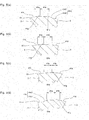
- the rake surface 8 sequentially includes a first rake surface 81 and a second rake surface 82.
- the first rake surface 81 is located along the cutting edge 5 and is inclined toward the lower surface 3 as going inward from the cutting edge 5 at a first rake angle ⁇ 1 on the basis of a perpendicular plane S1b perpendicular to the central axis S1 extending between the upper surface 2 and the lower surface 3.
- the second rake surface 82 is located more inward than the first rake surface 81 and is inclined toward the lower surface 3 at a second rake angle ⁇ 2 different from the first rake angle ⁇ 1 on the basis of the perpendicular plane S1b.
- An intersecting part 83 of the first rake surface 81 and the second rake surface 82 includes a protruded portion 831 located at the highest position in a region of the intersecting part 83 extending along the second side surface 42.
- the term “inward” denotes being located inside the insert 1 with respect to the cutting edge 5 and being located close to the through hole 6 (the central axis S1).
- the term “highest position” denotes being large in terms of height on the basis of the perpendicular plane S1b, namely, in terms of distance in the direction of the central axis S1 of the insert 1.
- the second rake angle ⁇ 2 of the second rake surface 82 may be partially identical to the first rake angle ⁇ 1 of the first rake surface 81.
- the protruded portion 831 is located closer to the corner side surface 43 than a midpoint 42A of the second side surface 42 in the top view as shown in Figs. 6(a) and 6(c) . This configuration ensures effective curling of the chips generated under the cutting conditions that the depth of cut is small as described above.
- the first rake angle ⁇ 1 of the first rake surface 81 reaches a minimum at a portion thereof passing through the protruded portion 831 as shown in Fig. 6(c) .
- This configuration makes it easier to create a difference in height between this portion and the portion located closer to the corner cutting edge 53 of the rake surface 8 particularly than the protruded portion 831.
- the second rake angle ⁇ 2 of the second rake surface 82 is decreased as going from the corner cutting edge 53 to the major cutting edge 51 side as shown in Fig. 7 .
- This configuration allows the second rake surface 82 to ensure a thickness on the first end portion 8a as shown in Fig. 1(a) , thereby reducing damage to the major cutting edge 51 in a region subjected to a large depth of cut.
- the first end portion 8a corresponds to one of both end portions of the rake surface 8 located along the major cutting edge 51, which is located further away from the minor cutting edge 52.
- a later-described second end portion 8b is one of both end portions of the rake surface 8 located along the major cutting edge 51, which is located close to the minor cutting edge 52.
- the first rake angle ⁇ 1 of the first rake surface 81 and the second rake angle ⁇ 2 of the second rake surface 82 include region in which a reversal of values occurs between the corner cutting edge 53 side and the major cutting edge 51 side as shown in Fig. 7 .
- the angles ⁇ 1 and ⁇ 2 have a relationship of ⁇ 1 ⁇ 2 in Fig. 7(b) , a relationship of ⁇ 1 ⁇ 2 in Fig. 7(c) , and a relationship of ⁇ 1> ⁇ 2 in Fig. 7(d) .
- the first rake angle ⁇ 1 and the second rake angle ⁇ 2 are subject to the reversal of values as going away from the corner cutting edge 53.
- This configuration ensures that the second rake surface 82 has a small inward-oriented width on the second end portion 8b in the top view, thereby ensuring a large area of the flat surface 21 so as to enhance attachment stability to the holder.
- This configuration also ensures a certain thickness on the first end portion 8a so as to reduce damage to the major cutting edge 51 in the region subjected to the large depth of cut.
- a relationship that the first rake angle ⁇ 1 is smaller than the second rake angle ⁇ 2 may be retained instead of the reversal of values between the above-mentioned portions.
- the first rake angle ⁇ 1 of the first rake surface 81 is subject to less variation than the second rake angle ⁇ 2 of the second rake surface 82 in the region from the first side surface 41 to the corner side surface 43 as shown in Fig. 7 .
- the rake surface 8 may be continuous with the major cutting edge 51 or disposed with a so-called land surface (land part) interposed therebetween.
- the term "land surface” denotes a narrow belt-shaped surface with a constant width disposed along the cutting edge 5 on the upper surface 2.
- the land surface is disposed for the purpose of reducing fracture of the cutting edge 5.
- the upper surface 2 further includes the land surface 22 disposed between the cutting edge 5 and the first rake surface 81 as shown in Figs. 6 and 7 .
- the land surface 22 lies over the whole periphery of the insert 1.
- the land surface 22 may be flat, or inclined as going inward from the cutting edge 5 in a direction toward the lower surface 3 or in a direction away from the lower surface 3 at a land angle ⁇ 3 on the basis of the perpendicular plane S1b.
- the land angle ⁇ 3 is determined as being plus (+) when the land surface 22 is inclined toward the lower surface 3, and as being minus (-) when the land surface 22 is inclined in the direction away from the lower surface 3, on the basis of the perpendicular plane S1b.
- the land surface 22 is inclined toward the lower surface 3 as going inward from the cutting edge 5 at the land angle ⁇ 3 on the basis of the perpendicular plane S1b. That is, in the present embodiment, the land angle ⁇ 3 is plus, and the land angle ⁇ 3 is smaller than the first rake angle ⁇ 1 of the first rake surface 81.
- the upper surface 2 and the lower surface 3 have the same configuration, and hence the description of the lower surface 3 is omitted in the following unless a special description is needed.
- the through hole 6 is the hole configured to insert a clamp screw and an attachment bolt when the insert 1 is attached to the holder 10.
- the through hole 6 is located in a central part of the upper surface 2, and the central axis of the through hole 6 and the central axis S1 of the insert 1 exist in the same position.
- the side surface 4 is connected to each of the upper surface 2 and the lower surface 3 as described above.
- the side surface 4 includes a first side surface 41 and a second side surface 42 adjacent to each other.
- the first side surface 41 and the second side surface 42 respectively include a plurality of constraining surfaces described later. According to an attachment direction with respect to the holder 10, the individual constraining surfaces function as an attachment surface to the holder 10, or as a so-called flank surface for avoiding contact with the workpiece 100.
- the side surface 4 further includes a corner side surface 43 that is disposed between the first side surface 41 and the second side surface 42, and is curved outward in the top view. That is, the side surface 4 sequentially includes the first side surface 41, the corner side surface 43, and the second side surface 42.
- the insert 1 of the present embodiment has the rectangular shape whose long sides correspond to an outer edge close to the first side surface 41 and short sides correspond to an outer edge close to the second side surface 42 in the top view.
- An end portion 52a of the minor cutting edge 52 spaced apart from the corner cutting edge 53 is located closer to the corner cutting edge 53 than a midpoint 42a of each of the short sides.
- the insert 1 of the present embodiment has the rectangular shape whose long sides correspond to the outer edge close to the first side surface 41 and short sides correspond to the outer edge close to the second side surface 42 in the top view. Therefore, a third side surface 41P to be paired with the first side surface 41 is located on the opposite side, and a fourth side surface 42P to be paired with the second side surface 42 is located on the opposite side.
- the third side surface 41P and the fourth side surface 42P respectively have the same structure as the first side surface 41 and the second side surface 42. Therefore, the descriptions of the first side surface 41 and the second side surface 42 are applicable to the descriptions of the third side surface 41P and the fourth side surface 42P in the following unless a special description is needed. This is also true for another corner side surface 43P to be paired with the corner side surface 43.
- a distance (width) W1 from the first side surface 41 to the third side surface 41P in the top view shown in Fig. 1(b) is larger than a distance (thickness) W2 from the upper surface 2 to the lower surface 3 in the side view shown in Figs. 1(c) and (d) . That is, the insert 1 of the present embodiment is a so-called lateral insert.
- the insert 1 is to be attached to the holder 10 by using the clamp screw 61 to be inserted into the through hole 6 as described later. With this configuration, the insert 1 has a large width so as to ensure that the rake surface 8 has desired size and shape, thereby improving the chip discharge performance. Additionally, the clamp screw 61 is to be inserted into the through hole 6. This configuration eliminates the need to increase the thickness of the insert 1 than necessary, thus reducing material costs.
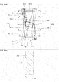
- the first side surface 41 sequentially includes a first upper constraining surface 41a and a first lower constraining surface 41b in a direction from the upper surface 2 to the lower surface 3.
- the first upper constraining surface 41a is inclined outward at an inclination angle ⁇ 1 on the basis of the central axis S1.
- the first lower constraining surface 41b is continuous with the first upper constraining surface 41a and is inclined inward at an inclination angle ⁇ 2.
- the first side surface 41 includes a first upper reinforcement surface 41c that is located between the major cutting edge 51 and the first upper constraining surface 41a, and has a portion inclined as going from the upper surface 2 to the lower surface 3 at an inclination angle ⁇ 3 on the basis of the central axis S1.
- the inclination angle ⁇ 3 of the first upper reinforcement surface 41c is larger than the inclination angle ⁇ 1 of the first upper constraining surface 41a.
- the first side surface 41 includes a first lower reinforcement surface 41d that is located between the major cutting edge 51A close to the lower surface 3 and the first lower constraining surface 41b, and is inclined as going from the upper surface 2 to the lower surface 3 at an inclination angle ⁇ 4 on the basis of the central axis S1.
- the inclination angle ⁇ 4 of the first lower reinforcement surface 41d is larger than the inclination angle ⁇ 2 of the first lower constraining surface 41b.
- the term “inclination angle ⁇ 1" denotes an angle formed by a plane S1a parallel to the central axis S1 and a virtual extension line L1 of the first upper constraining surface 41a.
- the term “inclination angle ⁇ 2” denotes an angle formed by the plane S1a and a virtual extension line L2 of the first lower constraining surface 41b.
- the term “inclination angle ⁇ 3” denotes an angle formed by the plane S1a and a virtual extension line L3 of the first upper reinforcement surface 41c.
- the term “inclination angle ⁇ 4" denotes an angle formed by the plane S1a and a virtual extension line L4 of the first lower reinforcement surface 41d.
- the individual inclination angles are indicated by an absolute value on the basis of the central axis S1.
- the insert 1 of the present embodiment has a relationship that the inclination angle ⁇ 1 equals to the inclination angle ⁇ 2, and also has a relationship that the inclination angle ⁇ 3 equals to the inclination angle ⁇ 4.
- the inclination angles ⁇ 1 and ⁇ 2 are respectively preferably set to 3° to 5°
- the inclination angles ⁇ 3 and ⁇ 4 are respectively preferably set to 4° to 7°.
- Each of these inclination angles may be changed as going away from the minor cutting edge 52.
- the first upper reinforcement surface 41c includes a first region 41cA close to the minor cutting edge 52 (corner cutting edge 53), and a second region 41cB spaced apart from the minor cutting edge 52 (corner cutting edge 53).
- the first region 41cA and the second region 41cB differ from each other in configuration.
- the straight line S1b is perpendicular to the central axis S1 and passes through the center in a thickness direction of the insert 1.
- the first upper reinforcement surface 41c is inclined outward in the first region 41cA as going from the upper surface 2 to the lower surface 3 as shown in Figs. 5(a) and 5(b) . More specifically, the first upper reinforcement surface 41c has a shape that bulges outward as going from the upper surface 2 to the lower surface 3. In the present embodiment, the region shown in Fig. 5(c) has a similar shape.
- an upper region 41c1 of the first upper reinforcement surface 41c which is continuous with the major cutting edge 51, is inclined inward with respect to the central axis S1 of the insert 1.
- a lower region 41c2 of the upper region 41c1, which is continuous with the lower surface 3, is inclined outward as going further toward the lower surface 3. More specifically, the lower region 41c2 has a shape that bulges outward as going further toward the lower surface 3.
- the upper region 41c1 of the first upper reinforcement surface 41c is inclined inward with respect to the central axis S1 of the insert 1. Accordingly, when the holder 10 with the insert 1 attached thereto is rotated around a rotation axis S2 of the holder 10, a clearance between the upper region 41c1 and a wall surface 101 of the workpiece 100 can be ensured to effectively reduce damage to the wall surface 101 of the workpiece 100. As shown in Fig. 5(a) , the same is true for the relationship between the upper region 41d1 and the lower region 41d2 of the first lower reinforcement surface 41d.
- the first side surface 41 further includes a first flank surface 41e.
- the first flank surface 41e is located below the major cutting edge 51 and closer to the second side surface 42 than both of the first upper reinforcement surface 41c and the first upper constraining surface 41a, and is inclined outward as going from the upper surface 2 to the lower surface 3 at an inclination angle ⁇ on the basis of the central axis S1.
- the inclination angle ⁇ (not shown) of the first flank surface 41e is smaller than the inclination angle ⁇ 3 of the first upper reinforcement surface 41c. Owing to the first flank surface 41e, the contact with a portion of the workpiece 100 that becomes the wall surface 101 of the workpiece 100 during the cutting process can be reduced to improve machining accuracy and reduce damage to the insert 1.
- the first flank surface 41e extends not only below the major cutting edge 51 as described above, but also below the corner cutting edge 53. Consequently, a similar effect is also attainable on the corner cutting edge 53.
- a boundary part 41g of the first upper constraining surface 41a and the first lower constraining surface 41b has a straight line shape and is inclined toward the lower surface 3 as going away from the minor cutting edge 52 with respect to a perpendicular line of the central axis S1 of the insert 1 in the side view.
- the boundary part 41g is located outermost of the first side surface 41.
- the boundary part 41g has a belt shape with a relatively large width, and has a curved surface shape protruding outward as going from one end to the other end in the width direction.
- This configuration ensures a relatively large area of the first upper constraining surface 41a and the first lower constraining surface 41b, and also ensures smooth loading of a material into a mold when molding the insert 1.
- a radius of curvature of a curved line is preferably set to, for example, 0.1 to 0.5 mm.
- the boundary part 41g may have a curved line shape partially or over the full length thereof in the side view.
- the first side surface 41 of the present embodiment includes portions (surfaces) 41a1 and 41a2 and portions (surfaces) 41b1 and 41b2, which are respectively obtained by dividing the first upper constraining surface 41a and the first lower constraining surface 41b into two portions by a concave part 41f located at an approximately middle part of the first side surface 41 as shown in Figs. 1(d) and 4(a) . That is, the first upper constraining surface 41a includes a first upper constraining portion 41a1 and a second upper constraining portion 41a2.
- the first lower constraining surface 41b includes a first lower constraining portion 41b1 and a second lower constraining portion 41b2.
- the three surfaces (41a1, 41a2, and 42a), including the second upper constraining surface 42a (or the second lower constraining surface 42b) of the second side surface 42, can be brought into contact with the holder 10, thus exhibiting the excellent attachment stability.
- the concave part 41f is preferably inclined toward the minor cutting edge 52 as going from the upper surface 2 to the lower surface 3 in the side view.
- This configuration allows the areas of the two divided constraining portions 41a1 and 41a2 (41b1 and 41b2) to approximate each other. Consequently, a cutting force applied mainly to the insert 1 during cutting of the workpiece 100 can be received by the two divided constraining portions 41a1 and 41a2 (41b1 and 41b2) in a well-balanced manner so as to improve the attachment stability.
- a depth 41f1 of the concave part 41f is preferably set to, for example, 0.03 to 0.15 mm.
- the second side surface 42 sequentially includes a second upper constraining surface 42a and a second lower constraining surface 42b in the direction from the upper surface 2 to the lower surface 3.
- the second upper constraining surface 42a is inclined inward at an inclination angle ⁇ 1 on the basis of the central axis S1.
- the second lower constraining surface 42b is continuous with the second upper constraining surface 42a and is inclined outward at an inclination angle ⁇ 2 on the basis of the central axis S1.
- the term "inclination angle ⁇ 1" denotes an angle formed by the plane S1a parallel to the central axis S1 and a virtual extension line L5 of the second upper constraining surface 42a.
- the term “inclination angle ⁇ 2" denotes an angle formed by the plane S1a and a virtual extension line L6 of the second lower constraining surface 42b.
- the insert 1 of the present embodiment has a relationship that the inclination angle ⁇ 1 equals to the inclination angle ⁇ 2.
- the inclination angles ⁇ 1 and ⁇ 2 are respectively preferably set to 4° to 8°.
- the second side surface 42 includes a second upper reinforcement surface 42c and a second lower reinforcement surface 42d as shown in Figs. 1(c) and 1(d) .
- the second upper reinforcement surface 42c is located between the minor cutting edge 52 and the second upper constraining surface 42a, and is approximately parallel to the central axis S1.
- the second lower reinforcement surface 42d is located between the major cutting edge 51A close to the lower surface 3 and the second lower constraining surface 42b, and is approximately parallel to the central axis S1.
- the second side surface 42 sequentially includes the second upper reinforcement surface 42c, the second upper constraining surface 42a, the second lower constraining surface 42b, and the second lower reinforcement surface 42d as going from the upper surface 2 to the lower surface 3.
- the second side surface 42 is capable of reducing the contact with the workpiece 100 during the cutting process owing to the second upper constraining surface 42a and the second lower constraining surface 42b.
- the second side surface 42 is also capable of exhibiting excellent cutting edge strength owing to the second upper reinforcement surface 42c and the second lower reinforcement surface 42d that are approximately parallel to the central axis S1.
- the lengths of the second upper reinforcement surface 42c and the second lower reinforcement surface 42d in the thickness direction of the insert 1 are decreased as going away from the corresponding major cutting edge 51 (corner cutting edge 53) according to the configuration that the minor cutting edge 52 is inclined in the straight line shape as described above.
- the insert 1 of the present embodiment having the foregoing configurations may be formed of a hard material, such as cemented carbide, ceramic, or cermet, or one obtained by coating any one of these base materials with a hard film of TiC, TiN, TiCN, or Al 2 O 3 by means of PVD or CVD.
- PVD-coated cemented carbide is preferred from the viewpoint of chipping resistance and the stability of a coating layer.
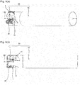
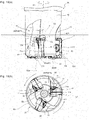
- a cutting tool according to an embodiment of the present invention is described below with reference to Figs. 8 to 10 .
- the cutting tool 20 of the present embodiment is configured to attach a plurality of inserts 1 described above to outer peripheral front end portions of the holder 10.
- a plurality of insert pockets 11 are disposed at spaced intervals in a circumferential direction in the outer peripheral front end portions of the holder 10 of the present embodiment.
- the insert pockets 11 are the portions obtained by cutting out the outer peripheral front end portions of the holder 10 in an approximately V shape in a front end view.
- a plurality of attachment surfaces of the insert pockets 11, which are formed by cutting out, function as attachment portions of the inserts 1.
- the inserts 1 are respectively attached to the insert pockets 11 one by one.
- a method of attaching the inserts 1 includes, for example, inserting a clamp screw 61 into each of the through holes 6 of the inserts 1, and screwing a front end portion of the clamp screw 61 to a screw hole 12 formed in each of the attachment surfaces of the holder 10.
- Another method of attaching the inserts 1 includes, for example, a clamp structure.
- the holder 10 (insert pockets) includes a seating surface 11c to be contacted with the lower surface 3 of the insert 1, and a first constraining surface 11a (contact surface) to be contacted with the first upper constraining surface 41a (third upper constraining surface 41Pa) of the insert 1.
- An angle ⁇ 1 formed by a virtual extension line L7 of the seating surface 11c and a virtual extension line L8 of the first constraining surface 11a is an acute angle.
- the holder 10 (insert pockets) includes a second constraining surface 11b (contact surface) to be contacted with the second lower constraining surface 42b (fourth lower constraining surface 42Pb) of the insert 1.
- An angle ⁇ 2 formed by the virtual extension line L7 of the seating surface 11c and a virtual extension line L9 of the second constraining surface 11b is an acute angle.
- Each of the inserts 1 is attached to the holder 11 in a state that the upper surface 2 is oriented forward in a rotation direction indicated by arrow I of Fig. 10 so as to allow the major cutting edge 51 to project beyond the outer periphery of the holder 10. Then, the first side surface 41 and the second side surface 42 are located close to the outer periphery of the front end of the holder 10, and the cutting process for the workpiece 100 is performed using the major cutting edge 51 and the minor cutting edge 52.
- the surface of the side surface 4 of the insert 1, which do not contribute to the cutting action, namely, the third side surface 41P and the fourth side surface 42P are respectively contacted with the contact surfaces of the holder 10. That is, the fourth lower constraining surface 42Pb of the fourth side surface 42P is contacted with the second constraining surface 11b of the holder 10 as shown by the region surrounded by a broken line 21 in Fig. 10(a) .
- the third upper constraining surface 41Pa of the third side surface 41P is contacted with the first constraining surface 11a of the holder 10 as shown by the region surrounded by a broken line 22 in Fig. 10(b) . Consequently, the insert 1 and the holder 10 are mutually constrained so that the insert 1 is attached to the holder 10.
- relatively large cutting force exerted on the major cutting edge 51 close to the first side surface 41 during the cutting process acts as force (buoyant force) by which the third side surface 41P of the insert 1 is lifted from the holder 10 in an arrowed direction Y1 via the clamp screw 61 inserted into the through hole 6.
- the angle ⁇ 1 is the acute angle
- the third upper constraining surface 41Pa of the third side surface 41P on which the buoyant force occurs can be pressed from above by the first constraining surface 11a of the holder 10, thereby effectively constraining the insert 1.
- relatively small cutting force exerted on the minor cutting edge 52 close to the second side surface 42 acts as force (buoyant force) by which the fourth side surface 42P of the insert 1 is lifted from the holder 10 in an arrowed direction Y2 via the clamp screw 61 inserted into the through hole 6.
- the angle ⁇ 2 is the acute angle
- the fourth lower constraining surface 42Pb of the fourth side surface 42P on which the buoyant force occurs can be pressed from above by the second constraining surface 11b of the holder 10, thereby effectively constraining the insert 1.
- the cutting tool 20 of the present embodiment is capable of generating appropriate constraining force according to the position subjected to the cutting force and the magnitude of the cutting force, thereby improving the stability of constraint of the insert 1 and the holder 10.
- the cutting tool 20 of the present embodiment it is ensured to improve the degree of freedom for the attachment of the foregoing inserts 1 to the holder 10, and to obtain excellent operation advantage based thereon. That is, as shown in Fig. 10(a) , the major cutting edge 51 is disposed so as to have a positive axial rake angle ⁇ 3. This configuration ensures reduction of cutting resistance.
- the second upper constraining surface 42a of the second side surface 42 is disposed so as to have a clearance angle ⁇ 4 of approximately 8° to 15°. This configuration ensures reduction of damage to the second upper constraining surface 42a, and also ensures improvement of surface roughness of the finished surface 102 of the workpiece 100.
- the axial rake angle ⁇ 3 of the major cutting edge 51 preferably reaches approximately 8° to 15° at the end portion thereof close to the minor cutting edge 52, and is preferably decreased as going away from the minor cutting edge 52.
- the term "axial rake angle ⁇ 3" denotes an inclination angle with respect to a plane S2a parallel to the rotation axis S2 of the holder 10.
- the term "clearance angle ⁇ 4" denotes an inclination angle with respect to a plane S2b perpendicular to the rotation axis S2 of the holder 10.
- the insert 1 is disposed so that the longitudinal direction thereof has an inclination of approximately 2° to 6° with respect to the rotation axis S2 of the holder 10 in the side view. Accordingly, the minor cutting edge 52 is disposed so as to have an inclination of approximately 0° to 1° with respect to the plane S2b perpendicular to the rotation axis S2 of the holder 10.
- the non-cutting region is spaced apart from the finished surface 102 of the workpiece 100 during the cutting process, and hence the contact therebetween can be suppressed to reduce damage to the non-cutting region. That is, when the insert 1 is used by turning over the upper surface 2 and the lower surface 3, the non-cutting region is capable of appropriately exhibiting the function as the minor cutting edge 52.
- the cutting process of the workpiece 100 using the major cutting edge 51 and the minor cutting edge 52 is performed by rotating the cutting tool 20 having the foregoing configurations in the arrowed I direction around the rotation axis S2 of the holder 10.
- the cutting tool 20 with the plurality of inserts 1 attached to the holder 10 as described above is prepared before starting the cutting process of the workpiece 100.
- the cutting tool 20 is disposed so that the rotation axis S2 of the holder 10 is approximately parallel to a surface of the workpiece 100 that is to become the wall surface 101 by being cut.
- the workpiece 100 is fixed to, for example, a bed for a milling machine (not shown), and the cutting tool 20 is moved in an arrowed direction II so as to set an appropriate depth of cut.
- the cutting tool 20 is fed (moved) in an arrowed direction III while rotating the cutting tool 20 around the arrowed direction I around the rotation axis S2 of the holder 10. Consequently, the major cutting edge 51 is brought into contact with a circular arc shaped part of the workpiece 100 located forward in the feed direction, thereby cutting a region according to the depth of cut.
- the plurality of inserts 1 sequentially enter a cutting region so as to perform cutting, so that circular arc lines (cutting marks) remain on the surface (bottom surface) of the workpiece 100. These circular arc shaped marks are then cut by the minor cutting edge 52, resulting in a smooth surface.
- the cutting tool 20 passes through the workpiece 100 and is then raised in an arrowed direction IV so as to separate the cutting tool 20 from the workpiece 100.
- the machined product 110 having the wall surface 101 and the finished surface 102 is produced through the foregoing individual steps. That is, the method of producing the machined product according to the present embodiment includes the step of cutting in which the cutting tool 20 is rotated so as to bring the individual inserts 1 into contact with the workpiece 100, and the step of separating the cutting tool 20 from the workpiece 100. These steps are sequentially performed to produce the machined product 110.
- the cutting process may be performed using the cutting edge 5 not yet being used by rotating the insert 1 about the central axis S1, or by turning over the upper surface 2 and the lower surface 3.
- the cutting tool 20 being rotated is moved with respect to the workpiece 100 in the foregoing embodiment.
- the cutting process may be performed by rotating the cutting tool 20 at a predetermined position, and by feeding the workpiece 100 with respect to the cutting tool 20.
- the foregoing embodiment has illustrated the milling machine as a machine tool.
- the cutting process may be performed by bringing the cutting tool 20 not being rotated and the workpiece 100 being rotated into contact with each other, as in the case of a lathe.
- the minor cutting edge 52 has the straight line shape in the top view in the foregoing embodiment.
- the minor cutting edge 52 may be formed of three straight line portions in the top view. Specifically, a first straight line shaped part in a middle region is located most outward of the insert 1, and second and third straight line shaped parts on both sides of the first straight line shaped part are respectively inclined inward as going away from the middle region.
- This configuration ensures a large clearance between the third straight line shaped part spaced apart from the major cutting edge 51 (corner cutting edge 53) on the upper surface 2 and the finished surface 102 of the workpiece 100 when the insert 1 is attached to the holder 10 in a state that the second straight line shaped part close to the major cutting edge 51 (corner cutting edge 53) is disposed along the finished surface 102 of the workpiece 100 and the upper surface 2 is oriented forward in the rotation direction.
- This configuration also ensures a large clearance between the second straight line shaped part of the minor cutting edge 52A close to the above-mentioned lower surface 3 configured correspondingly to the upper surface 2 and the finished surface 102 of the workpiece 100. Hence, the contact between the finished surface 102 and each of the second and third straight line shaped parts can be suppressed to enhance the surface accuracy of the finished surface 102 of the workpiece 100.
- the upper surface 2 may include a protruded surface that is located continuously with at least a part of the rake surface 8 and is inclined upward as going away from the major cutting edge 51.
- a first end portion 8a of the rake surface 8 located away from the minor cutting edge 52 is preferably continuous with the flat surface 21 with the protruded surface interposed therebetween.
- a second end portion 8b of the rake surface 8 located close to the minor cutting edge 52 is preferably continuous with the flat surface 21.
- a flat bottom portion may be disposed between the rake surface 8 and the protruded surface.
- the portion corresponding to the foregoing rake surface 8 and the flat surface 21 are preferably continuous with each other without disposing a portion inclined upward, such as the foregoing protruded surface, in a region of the upper surface 2 located inside the minor cutting edge 52.
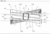
- the concave part 41f has the approximately constant width perpendicular to the thickness direction of the insert 1 in the side view in the foregoing embodiment.
- the concave part 41f may have the shape as shown in Fig. 12 in the side view.
- a concave part 41f' of this embodiment is located at an approximately middle part of the first side surface 41 in the side view, and has a width w perpendicular to the thickness direction of the insert 1.
- short sides 411 of the concave part 41f' are approximately parallel to the major cutting edges 51 and 51A, and the width w is parallel to a straight line connecting both ends of each of the short sides 411.
- the width w is narrow at positions close to the major cutting edges 51 and 51A, and is wide at positions away from the major cutting edges 51 and 51A.
- the constraining parts 41a1, 41a2, 41b1, and 41b2 respectively divided by the concave part 41f' can be relatively strongly brought into contact with the holder 10 even when the insert 1 is considerably deformed.
- the concave part 41f' is preferably narrowed at the positions close to the major cutting edges 51 and 51A. This configuration ensures retention of the strength of the major cutting edges 51 and 51A.
- the portions of the constraining parts 41a1, 41a2, 41b1, and 41b2, which are located on the circumference of the concave part 41f' and located close to the major cutting edges 51 and 51A, are particularly strongly brought into contact with the holder 10. It is therefore effective to make a modification to increase a contact length of the portions subjected to the particularly strong contact.
Claims (15)
- Schneideinsatz (1), aufweisend:eine obere Fläche (2),eine untere Fläche (3),eine Seitenfläche (4), die mit jeder von der oberen Fläche (2) und der unteren Fläche (3) verbunden ist und aufeinanderfolgend eine erste Seitenfläche (41), eine Eckenseitenfläche (43) und eine zweite Seitenfläche (42) aufweist, undeine Schneidkante (5), aufweisend eine Hauptschneidkante (51), die sich an einem Schnittteil der oberen Fläche (2) und der ersten Seitenfläche (41) befindet, und eine Eckenschneidkante (53), die sich an einem Schnittteil der oberen Fläche (2) und der Eckenseitenfläche (43) befindet,wobei die obere Fläche (2) aufeinanderfolgend eine erste Spanfläche (81) und eine zweite Spanfläche (82) aufweist, wobei die erste Spanfläche (81) entlang der Schneidkante (5) angeordnet und, von der Schneidkante (5) aus nach innen, in Richtung zu der unteren Fläche (3) in einem ersten Spanwinkel (θ1) auf einer Grundlage einer senkrechten Ebene (S1b) senkrecht zu einer sich zwischen der oberen Fläche (2) und der unteren Fläche (3) erstreckenden Mittelachse (S1) geneigt ist, wobei die zweite Spanfläche (82) weiter innen liegt als die erste Spanfläche (81) und in Richtung zu der unteren Fläche (3) in einem zweiten Spanwinkel (θ2), der sich von dem ersten Spanwinkel (θ1) unterscheidet, auf der Grundlage der senkrechten Ebene (S1b) geneigt ist, unddadurch gekennzeichnet, dassder erste Spanwinkel (θ1) der ersten Spanfläche (81) in einem Bereich, der sich von der ersten Seitenfläche (41) zu der Eckenseitenfläche (43) erstreckt, einer geringeren Variation als der zweite Spanwinkel (θ2) der zweiten Spanfläche (82) unterliegt.
- Schneideinsatz (1) gemäß Anspruch 1, wobeiein Schnittteil (83) der ersten Spanfläche (81) und der zweiten Spanfläche (82) einen hervorstehenden Teil (831) aufweist, der sich an einer höchsten Position in einem Bereich des Schnittteils befindet, der sich entlang der zweiten Seitenfläche (42) erstreckt, undder hervorstehende Teil (831) in einer Draufsicht näher bei der Eckenseitenfläche (43) liegt als ein Mittelpunkt (42A) der zweiten Seitenfläche (42).
- Schneideinsatz (1) gemäß Anspruch 1 oder 2, wobeiein Schnittteil (83) der ersten Spanfläche (81) und der zweiten Spanfläche (82) einen hervorstehenden Teil (831) aufweist, der sich an einer höchsten Position in einem Bereich des Schnittteils befindet, der sich entlang der zweiten Seitenfläche (42) erstreckt, undder erste Spanwinkel (θ1) der ersten Spanfläche (81) an einem Abschnitt, der durch den hervorstehenden Teil (831) hindurchverläuft, ein Minimum erreicht.
- Schneideinsatz (1) gemäß irgendeinem der Ansprüche 1 bis 3, wobei der zweite Spanwinkel (θ2) der zweiten Spanfläche (82) von der Eckenschneidkante (53) zu der Hauptschneidkantenseite (51) hin abnimmt.
- Schneideinsatz (1) gemäß irgendeinem der Ansprüche 1 bis 4, wobei der erste Spanwinkel (θ1) der ersten Spanfläche (81) und der zweite Spanwinkel (θ2) der zweiten Spanfläche (82) einen Bereich aufweisen, in dem eine Umkehrung von Werten des ersten Spanwinkels (θ1) und des zweiten Spanwinkels (θ2) zwischen der Eckenschneidkanten- (53) -seite und der Hauptschneidkanten- (51) -seite auftritt.
- Schneideinsatz (1) gemäß irgendeinem der Ansprüche 1 bis 4, wobei der erste Spanwinkel (θ1) der ersten Spanfläche (81) kleiner als der zweite Spanwinkel (θ2) der zweiten Spanfläche (82) ist.
- Schneideinsatz (1) gemäß irgendeinem der Ansprüche 1 bis 6, wobei die obere Fläche (2) ferner eine zwischen der Schneidkante (5) und der ersten Spanfläche (81) angeordnete Stegfläche (22) aufweist.
- Schneideinsatz (1) gemäß Anspruch 7, wobei die Stegfläche (22) auf der Grundlage der senkrechten Ebene (S1b) in einem Stegwinkel (θ3) geneigt ist und der Stegwinkel (θ3) kleiner als der erste Spanwinkel (θ1) der ersten Spanfläche (81) ist.
- Schneideinsatz (1) gemäß irgendeinem der Ansprüche 1 bis 8, wobei eine Nebenschneidkante (52), die sich an einem Schnittteil der oberen Fläche (2) und der zweiten Seitenfläche (42) befindet, in einer Seitenansicht weg von der Eckenschneidkante (53) in Richtung zu der unteren Fläche (3) geneigt ist.
- Schneideinsatz (1) gemäß irgendeinem der Ansprüche 1 bis 9,wobei der Schneideinsatz (1) in einer Draufsicht eine rechteckige Form hat, aufweisend lange Seiten, die einer Außenkante nahe bei der ersten Seitenfläche (41) entsprechen, und kurze Seiten, die einer Außenkante nahe bei der zweiten Seitenfläche (42) entsprechen, undwobei ein Endabschnitt (52a) einer Nebenschneidkante (52), der sich an einem Schnittteil der oberen Fläche (2) und der zweiten Seitenfläche (42) befindet, die im Abstand von der Eckenschneidkante (53) angeordnet ist, näher bei der Eckenschneidkante (53) angeordnet ist als ein Mittelpunkt (42a) der kurzen Seiten.
- Schneideinsatz (1) gemäß irgendeinem der Ansprüche 1 bis 10, ferner aufweisend ein Durchgangsloch (6), das sich zwischen der oberen Fläche (2) und der unteren Fläche (3) erstreckt.
- Schneideinsatz (1) gemäß Anspruch 1, wobei in der Seitenansicht die Hauptschneidkante (51) weg von der Nebenschneidkante (52) in Richtung zu der unteren Fläche (3) geneigt ist, und ein Neigungswinkel der Hauptschneidkante (51) weg von der Nebenschneidkante (52) allmählich kleiner wird.
- Schneideinsatz (1) gemäß irgendeinem der Ansprüche 1 bis 12, wobei die obere Fläche (2) ferner eine flache Fläche (21) aufweist, die im Abstand von der Schneidkante (5) angeordnet ist und sich zumindest teilweise über der Hauptschneidkante (51) befindet.
- Schneidwerkzeug (20), aufweisend:einen Schneideinsatz (1) gemäß irgendeinem der Ansprüche 1 bis 13 undeine Halterung (10), die konfiguriert ist, um den Schneideinsatz (1) an der Halterung (10) anzubringen.
- Verfahren zum Herstellen eines maschinell bearbeiteten Produkts, aufweisend:Drehen eines Schneidwerkzeugs (20) gemäß Anspruch 14,in-Kontakt-Bringen der Schneidkante (5) des Schneidwerkzeugs (20), das gedreht wird, mit einem Werkstück undTrennen des Schneidwerkzeugs (20) von dem Werkstück.
Applications Claiming Priority (2)
| Application Number | Priority Date | Filing Date | Title |
|---|---|---|---|
| JP2011239491 | 2011-10-31 | ||
| PCT/JP2012/072037 WO2013065393A1 (ja) | 2011-10-31 | 2012-08-30 | 切削インサートおよび切削工具、並びにそれを用いた切削加工物の製造方法 |
Publications (3)
| Publication Number | Publication Date |
|---|---|
| EP2774706A1 EP2774706A1 (de) | 2014-09-10 |
| EP2774706A4 EP2774706A4 (de) | 2015-08-05 |
| EP2774706B1 true EP2774706B1 (de) | 2020-11-04 |
Family
ID=48191752
Family Applications (1)
| Application Number | Title | Priority Date | Filing Date |
|---|---|---|---|
| EP12845789.2A Active EP2774706B1 (de) | 2011-10-31 | 2012-08-30 | Schneideeinsatz, schneidewerkzeug sowie herstellungsverfahren für ein schneideprodukt mit dem schneidewerkzeug |
Country Status (5)
| Country | Link |
|---|---|
| US (4) | US9272342B2 (de) |
| EP (1) | EP2774706B1 (de) |
| JP (3) | JP5824526B2 (de) |
| CN (2) | CN103889624B (de) |
| WO (1) | WO2013065393A1 (de) |
Families Citing this family (44)
| Publication number | Priority date | Publication date | Assignee | Title |
|---|---|---|---|---|
| KR20130024903A (ko) * | 2010-05-06 | 2013-03-08 | 가부시키가이샤 탕가로이 | 절삭용 인서트 및 인덱서블 절삭공구 |
| EP2623240B1 (de) * | 2010-09-30 | 2017-11-15 | Tungaloy Corporation | Schneidewerkzeug mit austauschbarer klingenkante |
| JP5568138B2 (ja) * | 2010-10-05 | 2014-08-06 | 京セラ株式会社 | 切削インサートおよび切削工具、並びにそれらを用いた切削加工物の製造方法 |
| JP5589244B2 (ja) * | 2010-10-06 | 2014-09-17 | 大昭和精機株式会社 | インサート |
| EP2703107B1 (de) * | 2011-04-26 | 2017-12-13 | Tungaloy Corporation | Schneideeinsatz und schneidewerkzeug |
| US10035198B2 (en) | 2011-11-15 | 2018-07-31 | Kennametal Inc. | Double-sided, indexable cutting insert with ramping capability and cutting tool therefor |
| US10201856B2 (en) * | 2012-05-24 | 2019-02-12 | Gershon System Ltd. | Method for designing a cutting edge of a cutting tool, cutting tools comprising the same, and cutting elements with multiple such cutting portions |
| DE102012108751A1 (de) * | 2012-09-18 | 2014-03-20 | Hartmetall-Werkzeugfabrik Paul Horn Gmbh | Schneideinsatz und Werkzeug zur spanenden Bearbeitung eines Werkstücks |
| DE102012108752B3 (de) * | 2012-09-18 | 2014-01-23 | Hartmetall-Werkzeugfabrik Paul Horn Gmbh | Schneideinsatz und Werkzeug zur spanenden Bearbeitung eines Werkstücks |
| US20150117969A1 (en) * | 2013-10-29 | 2015-04-30 | Kennametal Inc. | Cutting insert and shim for heavy machining operations |
| EP2893997B1 (de) * | 2014-01-08 | 2019-03-13 | Sandvik Intellectual Property AB | Fräswerkzeug |
| JP5790903B1 (ja) * | 2014-01-28 | 2015-10-07 | 三菱日立ツール株式会社 | インサート及び刃先交換式回転切削工具 |
| USD748703S1 (en) * | 2014-05-27 | 2016-02-02 | Korloy Inc. | Cutting insert |
| KR101469135B1 (ko) * | 2014-07-08 | 2014-12-04 | 한국야금 주식회사 | 절삭 인서트 및 이를 장착한 절삭 공구 |
| USD736841S1 (en) * | 2014-09-25 | 2015-08-18 | Taegutec Ltd. | Cutting insert |
| EP3000548B1 (de) * | 2014-09-26 | 2021-11-10 | Seco Tools Ab | Doppelseitige, quadratische Schulterfräsplatte |
| CN106715015B (zh) * | 2014-09-26 | 2018-09-28 | 京瓷株式会社 | 切削镶刀、切削工具以及切削加工物的制造方法 |
| USD755267S1 (en) * | 2014-12-10 | 2016-05-03 | Taegutec Ltd. | Cutting insert |
| US10046398B2 (en) * | 2014-12-15 | 2018-08-14 | Seco Tools Ab | Reinforced double-sided cutting insert and cutting tool with reinforced double-sided cutting insert |
| EP3072616B1 (de) * | 2015-03-25 | 2018-10-10 | Sandvik Intellectual Property AB | Schneideinsatz und fräswerkzeug |
| US9993884B2 (en) * | 2015-07-16 | 2018-06-12 | Kennametal Inc. | Double-sided tangential cutting insert |
| US9981323B2 (en) | 2015-07-16 | 2018-05-29 | Kennametal Inc. | Double-sided tangential cutting insert and cutting tool system using the same |
| US10076795B2 (en) * | 2015-11-19 | 2018-09-18 | Iscar, Ltd. | Triangular tangential milling insert and milling tool |
| JP6612152B2 (ja) * | 2016-03-03 | 2019-11-27 | 住友電工ハードメタル株式会社 | 切削インサートおよび切削工具 |
| JP1568740S (de) * | 2016-09-09 | 2017-02-06 | ||
| CN110234453B (zh) * | 2017-03-29 | 2021-01-26 | 京瓷株式会社 | 切削刀片、钻头以及切削加工物的制造方法 |
| CN110944777B (zh) * | 2017-08-02 | 2021-11-09 | 京瓷株式会社 | 切削刀片、切削工具以及切削加工物的制造方法 |
| EP3674023A4 (de) * | 2017-08-23 | 2021-05-26 | Kyocera Corporation | Einsatz |
| WO2019146645A1 (ja) * | 2018-01-23 | 2019-08-01 | 京セラ株式会社 | 切削インサート、切削工具及び切削加工物の製造方法 |
| EP3530391A1 (de) * | 2018-02-26 | 2019-08-28 | Seco Tools Ab | Schneideinsatz und werkzeugkörper für ein fräswerkzeug |
| EP3556498B1 (de) * | 2018-04-16 | 2021-02-17 | Seco Tools Ab | Schneideeinsatz und fräswerkzeug |
| JP7035176B2 (ja) * | 2018-05-07 | 2022-03-14 | 京セラ株式会社 | 切削インサート、切削工具及び切削加工物の製造方法 |
| WO2019230987A1 (ja) * | 2018-06-01 | 2019-12-05 | 京セラ株式会社 | 切削インサート、切削工具及び切削加工物の製造方法 |
| JP6507355B1 (ja) * | 2018-06-19 | 2019-05-08 | 株式会社タンガロイ | 切削インサート及び切削工具 |
| JP7257413B2 (ja) * | 2018-10-23 | 2023-04-13 | 京セラ株式会社 | 切削インサート、切削工具及び切削加工物の製造方法 |
| JP6744599B1 (ja) * | 2019-03-01 | 2020-08-19 | 株式会社タンガロイ | 切削インサート |
| EP3950188A4 (de) * | 2019-03-27 | 2022-06-01 | Sumitomo Electric Hardmetal Corp. | Schneideinsatz |
| AT16933U1 (de) * | 2019-07-11 | 2020-12-15 | Ceratizit Austria Gmbh | Doppelseitiger Schneideinsatz zum Fräsen |
| CN110449649B (zh) * | 2019-08-15 | 2021-08-03 | 株洲华锐精密工具股份有限公司 | 变前角铣削刀片 |
| JP6869492B2 (ja) * | 2019-08-28 | 2021-05-12 | 株式会社タンガロイ | 切削インサート |
| EP3808482A1 (de) * | 2019-10-14 | 2021-04-21 | Seco Tools Ab | Schneideeinsatz und fräswerkzeug |
| US20210138563A1 (en) * | 2019-11-13 | 2021-05-13 | Taegutec Ltd. | Cutting insert and cutting tool assembly including same |
| US11850670B2 (en) | 2020-04-24 | 2023-12-26 | Kennametal India Ltd. | Milling cutting inserts |
| JP6855024B1 (ja) * | 2020-10-02 | 2021-04-07 | 株式会社タンガロイ | 切削インサートおよびこれを備えた切削工具 |
Family Cites Families (52)
| Publication number | Priority date | Publication date | Assignee | Title |
|---|---|---|---|---|
| JPS59188104U (ja) * | 1983-05-27 | 1984-12-13 | 東芝タンガロイ株式会社 | スロ−アウエイチツプ |
| SE459326B (sv) * | 1987-11-03 | 1989-06-26 | Sandvik Ab | Vaendskaer foer spaanavskiljande bearbetning |
| JP2537102Y2 (ja) * | 1991-03-29 | 1997-05-28 | 三菱マテリアル株式会社 | スローアウェイチップ |
| JP2593408Y2 (ja) * | 1992-12-28 | 1999-04-12 | 京セラ株式会社 | スローアウェイインサート |
| SE500721C2 (sv) * | 1993-01-27 | 1994-08-15 | Sandvik Ab | Skär med vriden spånyta |
| SE500719C2 (sv) * | 1993-01-27 | 1994-08-15 | Sandvik Ab | Skär med skruvformigt vriden spånyta |
| ES2109088T3 (es) * | 1994-01-31 | 1998-01-01 | Widia Gmbh | Placa de corte giratoria y herramienta correspondiente. |
| JP3109561B2 (ja) * | 1995-03-08 | 2000-11-20 | 住友電気工業株式会社 | スローアウェイチップ及び切削工具 |
| JP3329159B2 (ja) * | 1995-10-25 | 2002-09-30 | 三菱マテリアル株式会社 | スローアウェイチップ及びスローアウェイ式転削工具 |
| IL119114A0 (en) * | 1996-08-22 | 1996-11-14 | Iscar Ltd | Cutting insert |
| JPH10146712A (ja) * | 1996-11-13 | 1998-06-02 | Mitsubishi Materials Corp | ボーリングカッタ |
| SE514014C2 (sv) * | 1998-05-06 | 2000-12-11 | Sandvik Ab | Vändskär för roterande fräsverktyg |
| IL127175A (en) * | 1998-11-20 | 2003-06-24 | Iscar Ltd | Cutting insert for mounting on a milling cutter |
| JP2001047306A (ja) * | 1999-08-09 | 2001-02-20 | Dijet Ind Co Ltd | スローアウェイチップ |
| JP4304935B2 (ja) | 2002-03-11 | 2009-07-29 | 三菱マテリアル株式会社 | 切削工具及びスローアウェイチップ |
| DE10317760B4 (de) | 2003-04-17 | 2005-08-25 | Walter Ag | Fräswerkzeug und Schneidplatte für ein solches |
| IL160223A (en) * | 2004-02-04 | 2008-11-26 | Carol Smilovici | Double-sided cutting insert and milling cutter |
| US7070363B2 (en) * | 2004-07-15 | 2006-07-04 | Kennametal Inc. | Cutting insert for high-speed milling cutter |
| US7104735B2 (en) | 2004-09-02 | 2006-09-12 | Ingersoll Cutting Tool Company | Tangential cutting insert and milling cutter |
| US7452167B2 (en) * | 2004-11-26 | 2008-11-18 | Kyocera Corporation | Cutting insert and milling tool |
| IL169491A (en) * | 2005-06-30 | 2009-06-15 | Carol Smilovici | Cutting insert |
| JP4491404B2 (ja) * | 2005-11-07 | 2010-06-30 | 住友電工ハードメタル株式会社 | 刃先交換式チップと刃先交換式隅削りフライスカッタ |
| KR100854278B1 (ko) * | 2006-12-28 | 2008-08-26 | 한국야금 주식회사 | 다기능 절삭공구 |
| US7963729B2 (en) * | 2007-01-18 | 2011-06-21 | Kennametal Inc. | Milling cutter and milling insert with coolant delivery |
| IL182100A (en) * | 2007-03-21 | 2010-11-30 | Taegutec India Ltd | Cutting insert for a milling cutter |
| IL182343A0 (en) * | 2007-04-01 | 2007-07-24 | Iscar Ltd | Cutting insert and tool for milling and ramping at high feed rates |
| BRPI0807914A2 (pt) * | 2007-04-26 | 2014-06-24 | Taegu Tec India P Ltd | Inserto de corte indexável de dupla extremidade, e, fresa. |
| SE531250C2 (sv) * | 2007-06-05 | 2009-02-03 | Sandvik Intellectual Property | Indexerbart hörnfrässkär |
| DE202008001348U1 (de) * | 2008-01-31 | 2009-06-10 | Kennametal Inc. | Bohrwerkzeug |
| DE102008027009B4 (de) * | 2008-06-06 | 2010-08-12 | Kennametal Inc. | Schneideinsatz für ein Zerspanungswerkzeug, sowie Werkzeugsitz und Schneidwerkzeug |
| CA2727599A1 (en) * | 2008-06-13 | 2009-12-17 | Taegutec Ltd. | Cutting insert |
| IL193284A (en) * | 2008-08-06 | 2014-06-30 | Iscar Ltd | Milling tools and cutting tool for it |
| WO2010100953A1 (ja) * | 2009-03-06 | 2010-09-10 | 三菱マテリアル株式会社 | 切削インサートおよびインサート着脱式切削工具 |
| EP2446992B1 (de) * | 2009-06-26 | 2017-09-20 | Kyocera Corporation | Schneideeinsatz, schneidewerkzeug sowie herstellungsverfahren für schneideprodukte damit |
| EP2481504B1 (de) * | 2009-09-25 | 2019-07-24 | Tungaloy Corporation | Schneideeinsatz und schneidewerkzeug |
| BR112012008834B1 (pt) | 2009-10-15 | 2021-04-13 | Tungaloy Corporation | Inserto de corte |
| WO2011052340A1 (ja) * | 2009-10-28 | 2011-05-05 | 京セラ株式会社 | 切削インサートおよび切削工具、並びにそれを用いた切削加工物の製造方法 |
| JP5441615B2 (ja) * | 2009-10-29 | 2014-03-12 | 京セラ株式会社 | 切削インサートおよび切削工具ならびに被削加工物の製造方法 |
| JP5357979B2 (ja) * | 2009-11-27 | 2013-12-04 | 京セラ株式会社 | 切削インサートおよび切削工具、並びにそれを用いた切削加工物の製造方法 |
| IL203283A (en) * | 2010-01-13 | 2014-02-27 | Iscar Ltd | Cutting put |
| JP5204927B2 (ja) * | 2010-06-30 | 2013-06-05 | 京セラ株式会社 | インサートおよび切削工具、並びにそれらを用いた切削加工物の製造方法 |
| WO2012020784A1 (ja) * | 2010-08-11 | 2012-02-16 | 京セラ株式会社 | 切削インサートおよび切削工具、並びにそれらを用いた切削加工物の製造方法 |
| EP2492035B1 (de) * | 2011-02-24 | 2016-01-13 | Seco Tools AB | Achteckiger Schneideinsatz mit Kantenabschnitt mit variablem Keilwinkel und Schneidwerkzeug |
| WO2012147923A1 (ja) * | 2011-04-28 | 2012-11-01 | 京セラ株式会社 | 切削インサートおよび切削工具、並びにそれを用いた切削加工物の製造方法 |
| US9475133B2 (en) * | 2011-06-30 | 2016-10-25 | Kyocera Corporation | Cutting insert, cutting tool, and method of manufacturing machined product using the same |
| US8573905B2 (en) * | 2012-03-22 | 2013-11-05 | Iscar, Ltd. | Triangular cutting insert and cutting tool |
| JP5591409B2 (ja) * | 2012-05-30 | 2014-09-17 | 京セラ株式会社 | 切削インサート、切削工具および被削加工物の製造方法 |
| US8708616B2 (en) * | 2012-07-06 | 2014-04-29 | Iscar, Ltd. | Rotary cutting tool and reversible cutting insert therefor |
| CN106413958B (zh) * | 2014-05-26 | 2018-12-04 | 株式会社泰珂洛 | 切削刀片、主体及切削刀具 |
| US9468983B2 (en) * | 2014-09-22 | 2016-10-18 | Iscar, Ltd. | Rotary cutting tool and reversible cutting insert having variable-width minor relief surfaces therefor |
| JP5988186B1 (ja) * | 2014-11-27 | 2016-09-07 | 株式会社タンガロイ | 切削インサート及び刃先交換式回転切削工具 |
| US9901992B2 (en) * | 2014-12-23 | 2018-02-27 | Iscar, Ltd. | Ramping insert and high-feed milling tool assembly |
-
2012
- 2012-08-30 US US14/354,775 patent/US9272342B2/en active Active
- 2012-08-30 JP JP2013541663A patent/JP5824526B2/ja active Active
- 2012-08-30 WO PCT/JP2012/072037 patent/WO2013065393A1/ja active Application Filing
- 2012-08-30 EP EP12845789.2A patent/EP2774706B1/de active Active
- 2012-08-30 CN CN201280052992.1A patent/CN103889624B/zh active Active
- 2012-08-30 CN CN201710558902.0A patent/CN107297531B/zh active Active
-
2015
- 2015-10-09 JP JP2015200722A patent/JP6095241B2/ja active Active
-
2016
- 2016-01-12 US US14/993,501 patent/US9604292B2/en active Active
-
2017
- 2017-02-16 JP JP2017026659A patent/JP6353941B2/ja active Active
- 2017-02-27 US US15/443,111 patent/US9889511B2/en active Active
-
2018
- 2018-01-02 US US15/860,326 patent/US10486247B2/en active Active
Non-Patent Citations (1)
| Title |
|---|
| None * |
Also Published As
| Publication number | Publication date |
|---|---|
| CN103889624B (zh) | 2017-07-04 |
| WO2013065393A1 (ja) | 2013-05-10 |
| CN107297531A (zh) | 2017-10-27 |
| US9272342B2 (en) | 2016-03-01 |
| US20140298967A1 (en) | 2014-10-09 |
| US20170252838A1 (en) | 2017-09-07 |
| EP2774706A1 (de) | 2014-09-10 |
| JP2016005864A (ja) | 2016-01-14 |
| JP6095241B2 (ja) | 2017-03-15 |
| JP5824526B2 (ja) | 2015-11-25 |
| US10486247B2 (en) | 2019-11-26 |
| US9604292B2 (en) | 2017-03-28 |
| US20160121411A1 (en) | 2016-05-05 |
| JP6353941B2 (ja) | 2018-07-04 |
| JP2017080889A (ja) | 2017-05-18 |
| CN103889624A (zh) | 2014-06-25 |
| US20180193928A1 (en) | 2018-07-12 |
| US9889511B2 (en) | 2018-02-13 |
| JPWO2013065393A1 (ja) | 2015-04-02 |
| CN107297531B (zh) | 2019-11-22 |
| EP2774706A4 (de) | 2015-08-05 |
Similar Documents
| Publication | Publication Date | Title |
|---|---|---|
| EP2774706B1 (de) | Schneideeinsatz, schneidewerkzeug sowie herstellungsverfahren für ein schneideprodukt mit dem schneidewerkzeug | |
| EP2604369B1 (de) | Schneideeinsatz, schneidewerkzeug und verfahren zur herstellung eines schneideartikels mithilfe des schneideeinsatzes und des schneidewerkzeugs | |
| EP2599571B1 (de) | Schneideeinsatz und schneidewerkzeug sowie herstellungsverfahren für schneidewerkstück damit | |
| US8979440B2 (en) | Cutting insert, cutting tool, and method of manufacturing machined product using them | |
| US8882408B2 (en) | Cutting insert, cutting tool, and method of manufacturing machined product using the same | |
| EP2495060B1 (de) | Schneideeinsatz und schneidewerkzeug sowie herstellungsverfahren für schneidewerkstück damit | |
| US8985915B2 (en) | Cutting insert, cutting tool, and method of manufacturing machined product using the same | |
| US8915681B2 (en) | Cutting insert, cutting tool, and method of manufacturing machined product using the same | |
| US9327354B2 (en) | Cutting insert, cutting tool, and method of producing machined product using the same | |
| EP2727672B1 (de) | Schneideeinsatz, schneidewerkzeug sowie herstellungsverfahren für ein schneideprodukt mit dem schneidewerkzeug | |
| EP2446992A1 (de) | Schneideeinsatz, schneidewerkzeug sowie herstellungsverfahren für schneideprodukte damit |
Legal Events
| Date | Code | Title | Description |
|---|---|---|---|
| PUAI | Public reference made under article 153(3) epc to a published international application that has entered the european phase |
Free format text: ORIGINAL CODE: 0009012 |
|
| 17P | Request for examination filed |
Effective date: 20140425 |
|
| AK | Designated contracting states |
Kind code of ref document: A1 Designated state(s): AL AT BE BG CH CY CZ DE DK EE ES FI FR GB GR HR HU IE IS IT LI LT LU LV MC MK MT NL NO PL PT RO RS SE SI SK SM TR |
|
| DAX | Request for extension of the european patent (deleted) | ||
| RA4 | Supplementary search report drawn up and despatched (corrected) |
Effective date: 20150707 |
|
| RIC1 | Information provided on ipc code assigned before grant |
Ipc: B23B 51/00 20060101ALI20150701BHEP Ipc: B23C 5/10 20060101ALI20150701BHEP Ipc: B23C 5/20 20060101AFI20150701BHEP Ipc: B23B 27/16 20060101ALI20150701BHEP Ipc: B23B 27/14 20060101ALI20150701BHEP Ipc: B23C 5/06 20060101ALI20150701BHEP |
|
| STAA | Information on the status of an ep patent application or granted ep patent |
Free format text: STATUS: EXAMINATION IS IN PROGRESS |
|
| 17Q | First examination report despatched |
Effective date: 20181119 |
|
| GRAP | Despatch of communication of intention to grant a patent |
Free format text: ORIGINAL CODE: EPIDOSNIGR1 |
|
| STAA | Information on the status of an ep patent application or granted ep patent |
Free format text: STATUS: GRANT OF PATENT IS INTENDED |
|
| INTG | Intention to grant announced |
Effective date: 20200529 |
|
| GRAS | Grant fee paid |
Free format text: ORIGINAL CODE: EPIDOSNIGR3 |
|
| GRAA | (expected) grant |
Free format text: ORIGINAL CODE: 0009210 |
|
| STAA | Information on the status of an ep patent application or granted ep patent |
Free format text: STATUS: THE PATENT HAS BEEN GRANTED |
|
| AK | Designated contracting states |
Kind code of ref document: B1 Designated state(s): AL AT BE BG CH CY CZ DE DK EE ES FI FR GB GR HR HU IE IS IT LI LT LU LV MC MK MT NL NO PL PT RO RS SE SI SK SM TR |
|
| REG | Reference to a national code |
Ref country code: GB Ref legal event code: FG4D |
|
| REG | Reference to a national code |
Ref country code: CH Ref legal event code: EP |
|
| REG | Reference to a national code |
Ref country code: AT Ref legal event code: REF Ref document number: 1330155 Country of ref document: AT Kind code of ref document: T Effective date: 20201115 |
|
| REG | Reference to a national code |
Ref country code: IE Ref legal event code: FG4D |
|
| REG | Reference to a national code |
Ref country code: DE Ref legal event code: R096 Ref document number: 602012073125 Country of ref document: DE |
|
| REG | Reference to a national code |
Ref country code: NL Ref legal event code: MP Effective date: 20201104 |
|
| REG | Reference to a national code |
Ref country code: AT Ref legal event code: MK05 Ref document number: 1330155 Country of ref document: AT Kind code of ref document: T Effective date: 20201104 |
|
| PG25 | Lapsed in a contracting state [announced via postgrant information from national office to epo] |
Ref country code: GR Free format text: LAPSE BECAUSE OF FAILURE TO SUBMIT A TRANSLATION OF THE DESCRIPTION OR TO PAY THE FEE WITHIN THE PRESCRIBED TIME-LIMIT Effective date: 20210205 Ref country code: PT Free format text: LAPSE BECAUSE OF FAILURE TO SUBMIT A TRANSLATION OF THE DESCRIPTION OR TO PAY THE FEE WITHIN THE PRESCRIBED TIME-LIMIT Effective date: 20210304 Ref country code: NO Free format text: LAPSE BECAUSE OF FAILURE TO SUBMIT A TRANSLATION OF THE DESCRIPTION OR TO PAY THE FEE WITHIN THE PRESCRIBED TIME-LIMIT Effective date: 20210204 Ref country code: FI Free format text: LAPSE BECAUSE OF FAILURE TO SUBMIT A TRANSLATION OF THE DESCRIPTION OR TO PAY THE FEE WITHIN THE PRESCRIBED TIME-LIMIT Effective date: 20201104 Ref country code: RS Free format text: LAPSE BECAUSE OF FAILURE TO SUBMIT A TRANSLATION OF THE DESCRIPTION OR TO PAY THE FEE WITHIN THE PRESCRIBED TIME-LIMIT Effective date: 20201104 |
|
| PG25 | Lapsed in a contracting state [announced via postgrant information from national office to epo] |
Ref country code: PL Free format text: LAPSE BECAUSE OF FAILURE TO SUBMIT A TRANSLATION OF THE DESCRIPTION OR TO PAY THE FEE WITHIN THE PRESCRIBED TIME-LIMIT Effective date: 20201104 Ref country code: IS Free format text: LAPSE BECAUSE OF FAILURE TO SUBMIT A TRANSLATION OF THE DESCRIPTION OR TO PAY THE FEE WITHIN THE PRESCRIBED TIME-LIMIT Effective date: 20210304 Ref country code: LV Free format text: LAPSE BECAUSE OF FAILURE TO SUBMIT A TRANSLATION OF THE DESCRIPTION OR TO PAY THE FEE WITHIN THE PRESCRIBED TIME-LIMIT Effective date: 20201104 Ref country code: SE Free format text: LAPSE BECAUSE OF FAILURE TO SUBMIT A TRANSLATION OF THE DESCRIPTION OR TO PAY THE FEE WITHIN THE PRESCRIBED TIME-LIMIT Effective date: 20201104 Ref country code: ES Free format text: LAPSE BECAUSE OF FAILURE TO SUBMIT A TRANSLATION OF THE DESCRIPTION OR TO PAY THE FEE WITHIN THE PRESCRIBED TIME-LIMIT Effective date: 20201104 Ref country code: AT Free format text: LAPSE BECAUSE OF FAILURE TO SUBMIT A TRANSLATION OF THE DESCRIPTION OR TO PAY THE FEE WITHIN THE PRESCRIBED TIME-LIMIT Effective date: 20201104 Ref country code: BG Free format text: LAPSE BECAUSE OF FAILURE TO SUBMIT A TRANSLATION OF THE DESCRIPTION OR TO PAY THE FEE WITHIN THE PRESCRIBED TIME-LIMIT Effective date: 20210204 |
|
| REG | Reference to a national code |
Ref country code: LT Ref legal event code: MG9D |
|
| PG25 | Lapsed in a contracting state [announced via postgrant information from national office to epo] |
Ref country code: HR Free format text: LAPSE BECAUSE OF FAILURE TO SUBMIT A TRANSLATION OF THE DESCRIPTION OR TO PAY THE FEE WITHIN THE PRESCRIBED TIME-LIMIT Effective date: 20201104 |
|
| PG25 | Lapsed in a contracting state [announced via postgrant information from national office to epo] |
Ref country code: LT Free format text: LAPSE BECAUSE OF FAILURE TO SUBMIT A TRANSLATION OF THE DESCRIPTION OR TO PAY THE FEE WITHIN THE PRESCRIBED TIME-LIMIT Effective date: 20201104 Ref country code: SK Free format text: LAPSE BECAUSE OF FAILURE TO SUBMIT A TRANSLATION OF THE DESCRIPTION OR TO PAY THE FEE WITHIN THE PRESCRIBED TIME-LIMIT Effective date: 20201104 Ref country code: RO Free format text: LAPSE BECAUSE OF FAILURE TO SUBMIT A TRANSLATION OF THE DESCRIPTION OR TO PAY THE FEE WITHIN THE PRESCRIBED TIME-LIMIT Effective date: 20201104 Ref country code: SM Free format text: LAPSE BECAUSE OF FAILURE TO SUBMIT A TRANSLATION OF THE DESCRIPTION OR TO PAY THE FEE WITHIN THE PRESCRIBED TIME-LIMIT Effective date: 20201104 Ref country code: CZ Free format text: LAPSE BECAUSE OF FAILURE TO SUBMIT A TRANSLATION OF THE DESCRIPTION OR TO PAY THE FEE WITHIN THE PRESCRIBED TIME-LIMIT Effective date: 20201104 Ref country code: EE Free format text: LAPSE BECAUSE OF FAILURE TO SUBMIT A TRANSLATION OF THE DESCRIPTION OR TO PAY THE FEE WITHIN THE PRESCRIBED TIME-LIMIT Effective date: 20201104 |
|
| REG | Reference to a national code |
Ref country code: DE Ref legal event code: R097 Ref document number: 602012073125 Country of ref document: DE |
|
| PG25 | Lapsed in a contracting state [announced via postgrant information from national office to epo] |
Ref country code: DK Free format text: LAPSE BECAUSE OF FAILURE TO SUBMIT A TRANSLATION OF THE DESCRIPTION OR TO PAY THE FEE WITHIN THE PRESCRIBED TIME-LIMIT Effective date: 20201104 |
|
| PLBE | No opposition filed within time limit |
Free format text: ORIGINAL CODE: 0009261 |
|
| STAA | Information on the status of an ep patent application or granted ep patent |
Free format text: STATUS: NO OPPOSITION FILED WITHIN TIME LIMIT |
|
| 26N | No opposition filed |
Effective date: 20210805 |
|
| PG25 | Lapsed in a contracting state [announced via postgrant information from national office to epo] |
Ref country code: IT Free format text: LAPSE BECAUSE OF FAILURE TO SUBMIT A TRANSLATION OF THE DESCRIPTION OR TO PAY THE FEE WITHIN THE PRESCRIBED TIME-LIMIT Effective date: 20201104 Ref country code: AL Free format text: LAPSE BECAUSE OF FAILURE TO SUBMIT A TRANSLATION OF THE DESCRIPTION OR TO PAY THE FEE WITHIN THE PRESCRIBED TIME-LIMIT Effective date: 20201104 Ref country code: NL Free format text: LAPSE BECAUSE OF FAILURE TO SUBMIT A TRANSLATION OF THE DESCRIPTION OR TO PAY THE FEE WITHIN THE PRESCRIBED TIME-LIMIT Effective date: 20201104 |
|
| PG25 | Lapsed in a contracting state [announced via postgrant information from national office to epo] |
Ref country code: SI Free format text: LAPSE BECAUSE OF FAILURE TO SUBMIT A TRANSLATION OF THE DESCRIPTION OR TO PAY THE FEE WITHIN THE PRESCRIBED TIME-LIMIT Effective date: 20201104 |
|
| REG | Reference to a national code |
Ref country code: CH Ref legal event code: PL |
|
| PG25 | Lapsed in a contracting state [announced via postgrant information from national office to epo] |
Ref country code: MC Free format text: LAPSE BECAUSE OF FAILURE TO SUBMIT A TRANSLATION OF THE DESCRIPTION OR TO PAY THE FEE WITHIN THE PRESCRIBED TIME-LIMIT Effective date: 20201104 |
|
| REG | Reference to a national code |
Ref country code: BE Ref legal event code: MM Effective date: 20210831 |
|
| GBPC | Gb: european patent ceased through non-payment of renewal fee |
Effective date: 20210830 |
|
| PG25 | Lapsed in a contracting state [announced via postgrant information from national office to epo] |
Ref country code: LI Free format text: LAPSE BECAUSE OF NON-PAYMENT OF DUE FEES Effective date: 20210831 Ref country code: CH Free format text: LAPSE BECAUSE OF NON-PAYMENT OF DUE FEES Effective date: 20210831 |
|
| PG25 | Lapsed in a contracting state [announced via postgrant information from national office to epo] |
Ref country code: IS Free format text: LAPSE BECAUSE OF FAILURE TO SUBMIT A TRANSLATION OF THE DESCRIPTION OR TO PAY THE FEE WITHIN THE PRESCRIBED TIME-LIMIT Effective date: 20210304 Ref country code: LU Free format text: LAPSE BECAUSE OF NON-PAYMENT OF DUE FEES Effective date: 20210830 |
|
| PG25 | Lapsed in a contracting state [announced via postgrant information from national office to epo] |
Ref country code: IE Free format text: LAPSE BECAUSE OF NON-PAYMENT OF DUE FEES Effective date: 20210830 Ref country code: GB Free format text: LAPSE BECAUSE OF NON-PAYMENT OF DUE FEES Effective date: 20210830 Ref country code: FR Free format text: LAPSE BECAUSE OF NON-PAYMENT OF DUE FEES Effective date: 20210831 Ref country code: BE Free format text: LAPSE BECAUSE OF NON-PAYMENT OF DUE FEES Effective date: 20210831 |
|
| PG25 | Lapsed in a contracting state [announced via postgrant information from national office to epo] |
Ref country code: HU Free format text: LAPSE BECAUSE OF FAILURE TO SUBMIT A TRANSLATION OF THE DESCRIPTION OR TO PAY THE FEE WITHIN THE PRESCRIBED TIME-LIMIT; INVALID AB INITIO Effective date: 20120830 Ref country code: CY Free format text: LAPSE BECAUSE OF FAILURE TO SUBMIT A TRANSLATION OF THE DESCRIPTION OR TO PAY THE FEE WITHIN THE PRESCRIBED TIME-LIMIT Effective date: 20201104 |
|
| P01 | Opt-out of the competence of the unified patent court (upc) registered |
Effective date: 20230508 |
|
| PGFP | Annual fee paid to national office [announced via postgrant information from national office to epo] |
Ref country code: DE Payment date: 20230705 Year of fee payment: 12 |