EP2773098B1 - Appareil d'imagerie par radiation, procédé d'imagerie par radiation et programme - Google Patents
Appareil d'imagerie par radiation, procédé d'imagerie par radiation et programme Download PDFInfo
- Publication number
- EP2773098B1 EP2773098B1 EP14154974.1A EP14154974A EP2773098B1 EP 2773098 B1 EP2773098 B1 EP 2773098B1 EP 14154974 A EP14154974 A EP 14154974A EP 2773098 B1 EP2773098 B1 EP 2773098B1
- Authority
- EP
- European Patent Office
- Prior art keywords
- scanning
- radiation
- reset
- image
- scanning lines
- Prior art date
- Legal status (The legal status is an assumption and is not a legal conclusion. Google has not performed a legal analysis and makes no representation as to the accuracy of the status listed.)
- Active
Links
- 230000005855 radiation Effects 0.000 title claims description 296
- 238000003384 imaging method Methods 0.000 title claims description 112
- 238000000034 method Methods 0.000 title claims description 17
- 238000001514 detection method Methods 0.000 claims description 125
- 238000012545 processing Methods 0.000 claims description 58
- 238000004891 communication Methods 0.000 claims description 35
- 238000012937 correction Methods 0.000 claims description 35
- 238000007599 discharging Methods 0.000 claims description 7
- 238000006243 chemical reaction Methods 0.000 description 30
- 238000012546 transfer Methods 0.000 description 30
- 238000009825 accumulation Methods 0.000 description 15
- 230000006866 deterioration Effects 0.000 description 15
- 230000007547 defect Effects 0.000 description 14
- 238000003702 image correction Methods 0.000 description 7
- 238000003745 diagnosis Methods 0.000 description 6
- OAICVXFJPJFONN-UHFFFAOYSA-N Phosphorus Chemical compound [P] OAICVXFJPJFONN-UHFFFAOYSA-N 0.000 description 5
- 238000010586 diagram Methods 0.000 description 4
- 230000008859 change Effects 0.000 description 3
- 230000002950 deficient Effects 0.000 description 3
- 230000006870 function Effects 0.000 description 3
- 230000035945 sensitivity Effects 0.000 description 3
- 230000005540 biological transmission Effects 0.000 description 2
- 239000000470 constituent Substances 0.000 description 2
- 230000007423 decrease Effects 0.000 description 2
- 230000000694 effects Effects 0.000 description 2
- 230000002401 inhibitory effect Effects 0.000 description 2
- 230000007246 mechanism Effects 0.000 description 2
- 238000012544 monitoring process Methods 0.000 description 2
- 238000005070 sampling Methods 0.000 description 2
- 230000003321 amplification Effects 0.000 description 1
- 238000013459 approach Methods 0.000 description 1
- 230000007274 generation of a signal involved in cell-cell signaling Effects 0.000 description 1
- 230000006872 improvement Effects 0.000 description 1
- 230000010365 information processing Effects 0.000 description 1
- 239000011159 matrix material Substances 0.000 description 1
- 238000012986 modification Methods 0.000 description 1
- 230000004048 modification Effects 0.000 description 1
- 238000003199 nucleic acid amplification method Methods 0.000 description 1
- 230000003287 optical effect Effects 0.000 description 1
- 230000000737 periodic effect Effects 0.000 description 1
- 230000008569 process Effects 0.000 description 1
- 230000009467 reduction Effects 0.000 description 1
Images


Classifications
-
- G—PHYSICS
- G01—MEASURING; TESTING
- G01T—MEASUREMENT OF NUCLEAR OR X-RADIATION
- G01T1/00—Measuring X-radiation, gamma radiation, corpuscular radiation, or cosmic radiation
- G01T1/16—Measuring radiation intensity
- G01T1/17—Circuit arrangements not adapted to a particular type of detector
-
- A—HUMAN NECESSITIES
- A61—MEDICAL OR VETERINARY SCIENCE; HYGIENE
- A61B—DIAGNOSIS; SURGERY; IDENTIFICATION
- A61B6/00—Apparatus or devices for radiation diagnosis; Apparatus or devices for radiation diagnosis combined with radiation therapy equipment
- A61B6/42—Arrangements for detecting radiation specially adapted for radiation diagnosis
- A61B6/4208—Arrangements for detecting radiation specially adapted for radiation diagnosis characterised by using a particular type of detector
- A61B6/4233—Arrangements for detecting radiation specially adapted for radiation diagnosis characterised by using a particular type of detector using matrix detectors
-
- A—HUMAN NECESSITIES
- A61—MEDICAL OR VETERINARY SCIENCE; HYGIENE
- A61B—DIAGNOSIS; SURGERY; IDENTIFICATION
- A61B6/00—Apparatus or devices for radiation diagnosis; Apparatus or devices for radiation diagnosis combined with radiation therapy equipment
- A61B6/58—Testing, adjusting or calibrating thereof
- A61B6/586—Detection of faults or malfunction of the device
-
- H—ELECTRICITY
- H04—ELECTRIC COMMUNICATION TECHNIQUE
- H04N—PICTORIAL COMMUNICATION, e.g. TELEVISION
- H04N25/00—Circuitry of solid-state image sensors [SSIS]; Control thereof
- H04N25/30—Circuitry of solid-state image sensors [SSIS]; Control thereof for transforming X-rays into image signals
-
- H—ELECTRICITY
- H04—ELECTRIC COMMUNICATION TECHNIQUE
- H04N—PICTORIAL COMMUNICATION, e.g. TELEVISION
- H04N25/00—Circuitry of solid-state image sensors [SSIS]; Control thereof
- H04N25/60—Noise processing, e.g. detecting, correcting, reducing or removing noise
- H04N25/63—Noise processing, e.g. detecting, correcting, reducing or removing noise applied to dark current
-
- H—ELECTRICITY
- H04—ELECTRIC COMMUNICATION TECHNIQUE
- H04N—PICTORIAL COMMUNICATION, e.g. TELEVISION
- H04N25/00—Circuitry of solid-state image sensors [SSIS]; Control thereof
- H04N25/60—Noise processing, e.g. detecting, correcting, reducing or removing noise
- H04N25/68—Noise processing, e.g. detecting, correcting, reducing or removing noise applied to defects
- H04N25/683—Noise processing, e.g. detecting, correcting, reducing or removing noise applied to defects by defect estimation performed on the scene signal, e.g. real time or on the fly detection
-
- H—ELECTRICITY
- H04—ELECTRIC COMMUNICATION TECHNIQUE
- H04N—PICTORIAL COMMUNICATION, e.g. TELEVISION
- H04N5/00—Details of television systems
- H04N5/30—Transforming light or analogous information into electric information
- H04N5/32—Transforming X-rays
Definitions
- the present invention relates to a radiation imaging apparatus, a method for radiation imaging, and a program.
- a radiation imaging system using a radiation generator which irradiates an object with radiation, a radiation imaging apparatus which generates a clear radiation image by performing image processing for the radiation image obtained by digitizing a radiation image as a radiation intensity distribution, and an image processing apparatus.
- the radiation irradiation apparatus irradiates an object with radiation
- the radiation imaging apparatus transfers obtained radiation image data to an image processing apparatus such as a control computer for image processing and saving.
- the image processing apparatus causes a display apparatus such as a display to display the processed image.
- the radiation imaging apparatus uses a sensor array having a two-dimensional array of pixels each including a conversion element which converts radiation into an image signal charge (electrical signals) and a switch element such as a TFT which transfers electrical signals to the outside. Performing matrix driving using switch elements such as TFTs transfers the signal charges converted by the conversion elements to a readout image processing apparatus, thereby forming an image from a readout charge amount.
- Each conversion element on the sensor array directly or indirectly generates signals upon being irradiated with radiation.
- the conversion element of each pixel detects the visible light converted from radiation by the phosphor instead of directly detecting the radiation.
- each pixel In either the direct or indirect sensor, each pixel generates and accumulates a certain level of a signal even without any radiation irradiation. This signal is called a dark charge here.
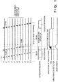
- the sensor array is configured to detect a change in the amount of current in each bias line while performing the reset scanning (TC101) of sequentially driving the respective rows (L0 to L10,...) on the sensor array to turn on the switch elements so as to reset charges in the respective pixels connected to the corresponding rows.
- the sensor array stops the reset scanning on the row on which it has executed reset scanning (TC102), and turns off the switch element to shift the sensor driving state to the state of accumulating operation for image signal charges originating from radiation (TC103). In this state, the sensor array detects radiation.
- the sensor array Upon completion of radiation irradiation, the sensor array sequentially drives the respective rows to turn on the switch elements to shift the sensor driving state to the state of output operation for image signal charges, thereby reading out the radiation image signals accumulated in the respective pixels (TC104).
- each pixel on the row in the process of reset operation at the time point (TC102) when the start of radiation irradiation is detected lets part of effective image signal charges generated by radiation irradiation flow out because the switch element is in the ON state.
- the radiation imaging apparatus may detect the start of irradiation with a delay.
- the sensor array performs reset scanning on a plurality of rows (L2 to L7 in the case shown in Fig. 1 ) from the row corresponding to the time point when the radiation irradiation apparatus has actually started irradiation to the row corresponding to the time point when the radiation imaging apparatus has detected the start of irradiation.
- effective image signal charges accumulated over a plurality of rows by radiation irradiation partly flow out.
- the pixel values on the rows (L2 to L7) from which effective charges flow out are smaller in charge amount than those on preceding and succeeding rows (L0, L1, L8 to L10,...), and hence lack in reliability.
- the apparatus disclosed in Japanese Patent Laid-Open No. 2011-249891 is configured to wait for the detection of the start of radiation irradiation while sequentially performing the above reset scanning (TC301) on rows which are not physically adjacent to each other as shown in Fig. 3 .
- the radiation imaging system is required to be capable of displaying a captured image immediately after the execution of imaging in order to quickly determine whether imaging has been normally performed (re-imaging is required).
- a captured image requires various types of image correction processing such as offset correction processing for correcting offset components in the image and the transfer time required to transfer the image to the display device, resulting in a delay time (display delay time) from imaging to the display of the image.
- Japanese Patent Laid-Open No. 2012-152340 discloses a method of transferring a preview image to a display device upon offset correction to reduce the display delay time.
- the present invention provides a radiation imaging technique which can reduce a display delay concerning a image and display the image without performing correction processing for an image deterioration at the time of the detection of radiation.
- the present invention in its first aspect provides a radiation imaging apparatus as specified in claims 1 to 13.
- the present invention in its second aspect provides a method for radiation imaging as specified in claim 14.
- the present invention in its third aspect provides a program as specified in claim 15.
- the present invention it is possible to reduce a display delay concerning an image and display the image without performing correction processing for an image deterioration at the time of the detection of radiation.
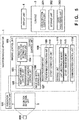
- Fig. 5 is a block diagram showing an example of the arrangement of a radiation imaging system according to an explanatory example.
- the radiation imaging system includes a radiation imaging apparatus 1, a console 3 (information processing apparatus) which controls the radiation imaging apparatus 1, a display unit 4, and a radiation generation unit 500 which irradiates an object with radiation.
- the radiation imaging apparatus 1 also includes a radiation detection unit 2 which generates image data by detecting radiation, an irradiation detection unit 101 which detects the start or end of radiation irradiation, and an imaging control unit 102 which controls imaging operation.
- the imaging control unit 102 includes a driving control unit 103 which controls the scanning driving of the radiation detection unit 2, an image acquisition control unit 107 which controls the acquisition of image data from the radiation detection unit 2, and an image processing unit 108 which performs signal processing such as offset correction and preview image generation.
- the imaging control unit 102 includes a storage unit 111 storing the obtained image obtained from the radiation detection unit 2 and a communication control unit 114 which controls data communication with the console 3, for example, transferring an obtained image to the console 3 outside the apparatus.
- the communication control unit 114 can use, for example, wireless LAN communication for data communication between the radiation imaging apparatus 1 and the console 3. Note that data communication is not limited wireless LAN communication, and wireless communication of another system or wired communication using a cable may be used.
- the driving control unit 103 includes a reset scanning control unit 105 for discharging (resetting) accumulated dark charges from the radiation detection unit 2 periodically or at an arbitrary timing.
- the driving control unit 103 includes a readout scanning control unit 106 which performs driving control to read out an image from the radiation detection unit 2, and an irradiation detection time information storage unit 104 for storing information concerning an irradiation time such as the number of the row on which reset scanning has been performed at the time point when radiation irradiation has started.
- the console 3 includes a communication control unit 301 which controls data communication between the radiation imaging apparatus 1 and the console 3, for example, receiving the captured image transferred from the radiation imaging apparatus 1.
- the console 3 includes a storage unit 302 for storing the reception image transferred and received from the radiation imaging apparatus 1 and an image processing unit 303 for correcting a reception image.
- the imaging control unit 102 reads out, for example, programs and the like saved in the storage unit 111, and performs overall control on the radiation imaging apparatus 1 based on the readout programs and the like.
- the imaging control unit 102 may control the radiation imaging apparatus 1 by performing apparatus control using a control signal generation circuit (control circuit) such as an ASIC or may implement overall control on the radiation imaging apparatus 1 by using both programs and the control circuit.
- control circuit control circuit
- the radiation detection unit 2 a plurality of conversion elements which convert radiation into charges are arranged along scanning lines in the row direction, and a plurality of scanning lines are arranged in the column direction.
- the radiation detection unit 2 is formed by arranging, in a two-dimensional array, pixels each including a switch element such as a TFT and a photoelectric conversion element (radiation detection element).
- a phosphor is provided on each pixel. In this case, radiation entering the radiation detection unit 2 is converted into visible light by the phosphor and strikes the photoelectric conversion element of each pixel. Each photoelectric conversion element then generates charges in accordance with the visible light.
- the radiation detection unit 2 can obtain a radiation image by executing charge accumulation and charge readout operation by switching on and off the TFTs.
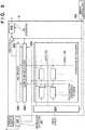
- Fig. 6 is a block diagram showing an example of the arrangement of the radiation detection unit 2.
- a drive circuit 201 simultaneously addresses the respective pixels on a row on the two-dimensional sensor array of the radiation detection unit 2.
- a sample and hold circuit 202 holds charges from the respective pixels on the row.
- a multiplexer 203 sequentially reads out the charges (pixel outputs) from the respective pixels which are held by the sample and hold circuit 202.
- An amplifier 205 amplifies the readout charges.
- An A/D converter 206 then converts the charges into image data with a digital value. Every time scanning on each row is complete, the drive circuit 201 sequentially performs scanning by driving each next row on the two-dimensional sensor array, and finally converts the charges output from all the pixels into digital values.
- the radiation detection unit 2 scans the respective pixels on a row while fixing a voltage applied to each column signal line connected to the pixels to a specific value, and discharges dark charges by discarding obtained charges, thereby discharging (resetting) the dark charges accumulated in the respective pixels.
- the driving control unit 103 performs control operation such as driving of the detection unit and readout operation.
- a captured image memory 112 stores the radiation image data in Fig. 5 . If the above image data is offset image data obtained from dark charge components from the respective pixels without performing radiation irradiation, an offset image memory 113 in Fig. 5 stores the offset image data.
- An offset correction unit 110 included in the image processing unit 108 can obtain a captured image from which unnecessary dark charge components are removed by performing the offset correction of subtracting offset image data components from radiation image data.
- the irradiation detection unit 101 which detects the start and end of radiation irradiation can include an independent sensor for radiation detection other than the radiation detection unit 2 which obtains images.
- the radiation detection unit 2 can implement detection of the start and end of irradiation by itself by monitoring the amount of dark charges discharged during reset scanning on the radiation detection unit 2.
- Offset image data is obtained, for example, after radiation imaging.
- the offset correction unit 110 then performs offset correction.
- the acquisition timing of offset image data is not limited to that after radiation imaging.
- offset image data may be obtained before radiation imaging.
- one offset image prepared in advance may be repeatedly used for offset correction processing.
- the image processing unit 108 in the radiation imaging apparatus 1 also includes a preview image generation unit 109 which generates a preview image by reducing a captured image from which unnecessary dark charge components are removed.
- the preview image generation unit 109 generates a preview image in advance from a radiation captured image before offset correction after the acquisition of the captured image.
- the preview image generation unit 109 then transfers the preview image generated in advance to the console 3 under the control of the communication control unit 114 to allow the display unit 4 connected to the console 3 to display the preview image generated in advance. Thereafter, the captured image for which offset correction is executed by the offset correction unit 110 and which is not reduced is transferred to the console 3 under the control of the communication control unit 114.
- the display unit 4 connected to the console 3 displays the transferred captured image as an actual image.
- the communication control unit 301 of the console 3 controls data transmission/reception with respect to the radiation imaging apparatus 1.
- the communication control unit 301 controls data transmission/reception with respect to the imaging control unit 102 by operating software incorporated in a computer or the like to set parameters such as an imaging region and imaging conditions.
- the image processing unit 303 of the console 3 performs image processing to form the captured image received from the radiation imaging apparatus 1 into a shape suitable for diagnosis.
- the storage unit 302 of the console 3 stores the captured image received from the radiation imaging apparatus 1.
- the display unit 4 displays the radiation captured image based on the charges read out from the radiation detection unit 2, an operation UI, and the like based on the captured image data transmitted to the console 3.
- Fig. 7 is a timing chart showing an imaging sequence in the radiation imaging system according to this explanatory example.
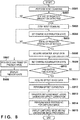
- Fig. 8 is a flowchart for explaining a procedure for an imaging sequence in the radiation imaging system. The operation of the radiation imaging system will be described with reference to Figs. 7 and 8 .
- the reset scanning control unit 105 of the driving control unit 103 periodically executes reset scanning to prevent dark charges from being accumulated in the two-dimensional sensor array forming the radiation detection unit 2 (TC701 in Fig. 7 and step S801 in Fig. 8 ).
- the reset scanning control unit 105 selects scanning lines as reset scanning targets so as to sequentially perform reset scanning (TC701) on conversion elements on rows (scanning lines) which are not physically adjacent to each other on the two-dimensional sensor array, and sequentially drives the conversion elements on the selected scanning lines.
- the reset scanning control unit 105 waits for radiation irradiation while discharging dark charges by repeating the first partial reset scanning and the second partial reset scanning. Note that the selection order of reset scanning is a mere example, and the reset scanning control unit 105 may perform the second partial reset scanning first, and then perform the first partial reset scanning after the second partial reset scanning.
- this explanatory example exemplifies the case in which the reset scanning control unit 105 scans every other row as rows (scanning lines) which are not adjacent to each other.
- the scope of the present invention is not limited to this.
- the reset scanning control unit 105 scans the (3 x n)th row in the first partial reset scanning, scans the (3 x n + 1)th row in the second partial reset scanning, and scans the (3 x n + 2)th row in the third partial reset scanning.
- the reset scanning control unit 105 scans the (4 x n)th row in the first partial reset scanning, scans the (4 x n + 1)th row in the second partial reset scanning, scans the (4 x n + 2)th row in the third partial reset scanning, and scans the (4 x n + 3)th row in the fourth partial reset scanning.
- the reset scanning control unit 105 may scan every arbitrary number (m - 1: m is an integer equal to or more than 2) of rows and may repeat reset scanning up to the mth partial reset scanning.
- the reset scanning control unit 105 may select a plurality of rows and perform reset scanning on them at once as long as they are not adjacent rows. When, for example, scanning every three rows, the reset scanning control unit 105 may simultaneously select rows and perform reset scanning on them in the first partial reset scanning and the third partial reset scanning. In addition, the reset scanning control unit 105 may simultaneously select rows and perform reset scanning on them in the second partial reset scanning and the fourth partial reset scanning.
- step S802 the irradiation detection unit 101 determines whether the radiation generation unit 500 has started radiation irradiation. If the irradiation detection unit 101 does not detect the start of radiation irradiation (NO in step S802), the reset scanning control unit 105 repeatedly executes reset scanning (step S801).
- the irradiation detection unit 101 detects this. If the irradiation detection unit 101 detects the start of radiation irradiation (YES in step S802), the reset scanning control unit 105 stops reset scanning (TC702 and step S803). The readout scanning control unit 106 turns off all the TFT switches on the two-dimensional sensor array, and sets all the pixels on the two-dimensional sensor array in the charge accumulation state (TC703 and step S804). When the reset scanning control unit 105 stops reset scanning, the sensor driving state shifts to the charge accumulation state.
- the driving control unit 103 stores information on the two-dimensional sensor array at the time of the stop of reset scanning in the irradiation detection time information storage unit 104. That is, the driving control unit 103 stores, in the irradiation detection time information storage unit 104, information concerning a row number corresponding to the time when reset scanning is stopped, the type of partial reset scanning when reset scanning is stopped, an output value corresponding to the time when irradiation is detected, and the like. Referring to Fig. 7 , the row number corresponding to the time when reset scanning is stopped is 8 (L8).
- the type of partial reset scanning indicates information for selecting rows (scanning lines) which are not adjacent to each other at the time of the execution of reset scanning, for example, information indicating scanning on every other row, scanning on every two rows, or scanning on every three rows.
- step S805 the irradiation detection unit 101 determines whether radiation irradiation is complete. If radiation irradiation is not complete (NO in step S805), the apparatus continues charge accumulating operation (TC703 and step S804).
- the readout scanning control unit 106 turns off all the TFT switches on the two-dimensional sensor array to set all the pixels on the two-dimensional sensor array in the charge output state. To read out the charges accumulated by radiation irradiation, the readout scanning control unit 106 performs readout scanning control (TC704) to sequentially scan rows on the two-dimensional sensor array, and obtains radiation image data captured by radiation (step S806).
- the captured image memory 112 stores the radiation image data obtained in this case.
- radiation image data can deteriorate in quality on some rows due to a detection delay from the start of actual radiation irradiation to the detection of the start of irradiation by the irradiation detection unit 101.
- the readout scanning control unit 106 obtains information concerning the two-dimensional sensor array at the time of the stop of reset scanning, which is stored in the irradiation detection time information storage unit 104. The readout scanning control unit 106 then specifies defective image data of the radiation image data.
- the irradiation detection unit 101 detects the start of radiation irradiation during partial reset scanning on the (2 x n)th row. Therefore, as shown in Fig. 4 , defects have occurred in radiation image data on the reset row (L8) corresponding to the time when reset scanning is stopped and the preceding (2 x n)th rows (L2, L4 and L6) .
- the irradiation detection unit 101 may detect the end of radiation irradiation, or the imaging control unit 102 may start readout operation upon standing by for a specific fixed time, with the corresponding timing being regarded as the end of irradiation.
- the two-dimensional sensor array detects the end of irradiation by itself, it is possible to detect the end of irradiation by, for example, keeping the TFT switch on on the row on which reset scanning has been performed at the start of irradiation without turning the TFT switch off, and keeping monitoring the amount of current flowing in the bias line.
- the preview image generation unit 109 of the image processing unit 108 decides image data to be used for the generation of a preview image. No image deterioration has occurred in image data on the (2 x n + 1)th rows selected in the second partial reset scanning, on which no reset scanning has been performed at the start of radiation irradiation, because no effective charges flow out by reset.
- the preview image generation unit 109 of the image processing unit 108 decides image data on rows other than the rows selected in the partial reset scanning executed at the time of the detection of the start of irradiation as image data to be used for the generation of a preview image, and generates a preview image from the image data (TC705 and step S807).
- the communication control unit 114 transfers the preview image generated by the preview image generation unit 109 to the console 3 before an actual image for diagnosis (TC705 and step S807).
- the preview image transferred to the console 3 requires no deteriorated image correction processing because there is no image deterioration at the time of the detection of irradiation, and can be instantaneously displayed on the display unit 4 (TC706 and step S808).
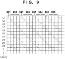
- the preview image generation unit 109 of the image processing unit 108 may generate a preview image by further thinning out and reducing data on rows other than rows selected in partial reset scanning at the time of the detection of irradiation (image data on the (2 x n + 1)th row).
- the preview image generation unit 109 can generate a reduced preview image by reducing a captured image by thinning out pixels as shown in Fig. 9 and then transfer the image to the console 3.
- a hatched pixel 901 is used for the generation (sampling) of a reduced preview image, and blanked pixels 902 to 905 are thinned out.
- a method of generating a reduced preview image by using the preview image generation unit 109 the method to be used is not limited to that exemplified by Fig. 9 , and another thinning-out method can be used.
- the preview image generation unit 109 may generate a reduced preview image by using interpolation processing among pixels to be used for the generation of a reduced preview image.
- a reduced preview image by combining the pixel values of pixels used for the generation of a reduced preview image with interpolation processing.
- the thinning-out ratio to be set is not limited to that exemplified in Fig. 9 , and various ratios can be set.
- the readout scanning control unit 106 Upon completing the readout operation for the radiation image data (step S806), the readout scanning control unit 106 turns off the TFT switches of all the pixels on the two-dimensional sensor array to set the charge accumulation state (TC707 and step S809).
- the readout scanning control unit 106 executes the processing in this step concurrently with the generation/transfer processing of a preview image (TC705 and step S807) and preview image display processing (TC706 and step S808) described above. Performing concurrent processing in this manner can shorten the time from the generation and display of a preview image to the generation and display of an actual image for diagnosis (to be described later).
- step S810 the readout scanning control unit 106 determines whether the same waiting time as the accumulation time at the time of radiation irradiation (TC703 and step S804) has elapsed (the waiting time has elapsed). If this waiting time has not elapsed (NO in step S810), the readout scanning control unit 106 continues charge accumulating operation. This continues the accumulation of dark charges. Upon determining that the same time as the accumulation time at the time of radiation irradiation has elapsed (YES in step S810), the readout scanning control unit 106 turns on all the TFT switches on the two-dimensional sensor array to set all the pixels on the two-dimensional sensor array in the charge output state. The readout scanning control unit 106 then executes readout operation to obtain the offset image data of only dark charge components (TC708 and step S811) .
- the offset correction unit 110 performs offset correction by using all the radiation image data stored in the captured image memory 112 and the obtained offset image data (step S812).
- the offset correction unit 110 obtains a captured image from which dark charge components are removed by the offset correction of subtracting offset image data components from the radiation image data.
- the communication control unit 114 transfers the captured image, for which offset correction has been performed by the offset correction unit 110, as an actual image to the console 3 (TC709 and step S813).
- the driving control unit 103 reads out, from the irradiation detection time information storage unit 104, information (information at the time of the detection of irradiation) concerning the two-dimensional sensor array at the time of the stop of reset scanning.
- the communication control unit 114 transfers the information at the time of the detection of irradiation, read out by the driving control unit 103, to the console 3.
- the image processing unit 303 of the console 3 specifies, from the information at the time of the detection of irradiation, information concerning a row number corresponding to the time when reset scanning is stopped, the type of partial reset scanning when partial reset scanning is stopped (a method of selecting rows (scanning lines) which are not adjacent to each other), an output value corresponding to the time when irradiation is detected, and the like.
- the image processing unit 303 performs image correction so as to interpolate defects in the received captured image by using the specified information and performs image processing suitable for each type of diagnosis (TC710 and step S814).
- the display unit 4 displays the captured image for which image processing has been performed by the image processing unit 303 (TC711 and step S815: display of actual image).
- the image processing unit 303 of the console 3 executes image defect correction processing at the time of the detection of irradiation.
- the present invention is not limited to this, and the image processing unit 108 in the radiation imaging apparatus 1 may execute this processing. In this case, it is not necessary to transfer the information at the time of the detection of irradiation to the console 3, and the image processing unit 108 may perform correction processing by using the information.
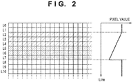
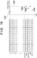
- a reset row at the time of the detection of the start of radiation irradiation is located near the head of a row selected by partial reset scanning, an image deterioration due to an irradiation start detection delay may also appear across the vicinity of the last row on which partial reset scanning has been executed at the immediately preceding timing.
- a reset row at the time of the detection of the start of irradiation is the first row (L0) at the time of the first partial reset scanning
- an image deterioration also appears across the vicinity of the last row (L2(n - 2) + 1, L2(n - 1) + 1, and L2n + 1)) in the second partial reset scanning executed earlier.
- each pixel exhibits a pixel value 1001.
- the first row (L0) at the time of first partial reset scanning is a reset row at the time of the detection of the start of radiation irradiation
- a pixel value 1002 of the first row (L0) is much lower than the pixel value 1001 as a reference.
- a pixel value 1003 of a row L2(n - 2) + 1, a pixel value 1004 of a row L2(n - 1) + 1, and a pixel value 1005 of a row L2n + 1 near the last row in the second partial reset scanning gradually decrease relative to the pixel value 1001 as the reference and approach the pixel value 1002 of the first row (L0).
- a preview image is generated from image data on a row ((2 x n + 1)th row) selected in the second partial reset scanning but not subjected to reset scanning at the time of the detection of irradiation.
- a most noticeable image deterioration appears on a row (for example, L7 in Fig. 2 ) at the time of the stop of reset scanning, which exhibits the largest change in pixel value in the column direction and on which a level difference occurs.
- Fig. 10 although image deteriorations have also occurred in the image data on the (2 x n + 1)th row used as a preview image, they do not look as level differences but look as gradual gradation on an end portion. Therefore, they have little influence on the display of a preview image.
- the radiation imaging apparatus is the radiation imaging apparatus including the radiation detection unit 2 including a radiation detection array 204 having a plurality of pixels configured to detect radiation and accumulates charges and arranged two-dimensionally and a plurality of scanning lines for sequentially discharging the charges accumulated in the pixels on a line basis.
- the reset scanning control unit 105 functioning as a reset control unit of the radiation imaging apparatus sequentially selects scanning lines which are not adjacent to each other and performs reset scanning.
- the irradiation detection unit 101 detects the start of radiation irradiation based on the charges discharged by reset scanning.
- the imaging control unit 102 performs control to stop reset scanning in accordance with the detection of the start of irradiation and obtain image signals by reading out charges accumulated in the pixels of the radiation detection array 204 by radiation irradiation.
- the preview image generation unit 109 functioning as a generation unit of the radiation imaging apparatus generates image data based on image signals from which image signals from scanning lines on which reset scanning has been performed during radiation irradiation are removed.
- the communication control unit 114 functioning as an output unit of the radiation imaging apparatus outputs image data to an external apparatus.
- the imaging control unit 102 reads out charges, from which image signals are obtained, starting from the scanning line on which reset scanning is stopped.
- the reset scanning control unit 105 sequentially selects scanning lines in accordance with a predetermined sequence.
- the imaging control unit 102 reads out charges, from which image signals are obtained, in accordance with a predetermined sequence, starting from the scanning line on which reset scanning is stopped.
- the preview image generation unit 109 generates image data based on image signals corresponding to the scanning line from which readout operation has started to the N/2th scanning line from which readout operation is performed, with N representing the total number of lines from which image signals are obtained.
- the communication control unit 114 outputs the image data generated by the preview image generation unit 109 and then outputs another image data containing image signals from scanning lines on which reset scanning has performed during radiation irradiation to an external apparatus.
- the reset scanning control unit 105 separately performs reset scanning on even-numbered lines and odd-numbered lines in accordance with a predetermined sequence. If a line on which reset scanning is stopped is an even-numbered line, the preview image generation unit 109 generates image data based on image signals from an odd-numbered line. If a line on which reset scanning is stopped is an odd-numbered line, the preview image generation unit 109 generates image data based on image signals from an even-numbered line.
- the radiation imaging apparatus is the radiation imaging apparatus including the radiation detection unit having the radiation detection array 204 having a plurality of pixels configured to detect radiation and accumulate charges and arranged two-dimensionally and a plurality of scanning lines for discharging the charges accumulated in the pixels.
- the reset scanning control unit 105 functioning as a reset control unit of the radiation imaging apparatus performs reset scanning to sequentially discharge charges accumulated in the pixels of the radiation detection array 204.
- the irradiation detection unit 101 detects the start of radiation irradiation based on charges discharged by reset scanning.
- the imaging control unit 102 performs control to stop reset scanning in accordance with the detection of the start of irradiation and obtain image signals by reading out charges accumulated in the pixels of the radiation detection array 204 by radiation irradiation.
- the preview image generation unit 109 functioning as a generation unit of the radiation imaging apparatus generates image data based on image signals from which image signals from pixels on which reset scanning has been performed during radiation irradiation are removed.
- the communication control unit 114 functioning as an output unit of the radiation imaging apparatus outputs image data to an external apparatus.
- a radiation imaging system according to a second explanatory example will be described next. Since the arrangement of the radiation imaging system according to this explanatory example is the same as that of the radiation imaging system according to the first explanatory example described above, a description of each constituent element will be omitted.
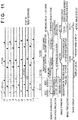
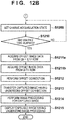
- Figs. 11 , 12A and 12B are a timing chart and a flowchart, respectively, showing an imaging sequence in the radiation imaging system according to this explanatory example. The operation of the radiation imaging system will be described with reference to Figs. 11 , 12A and 12B .
- a reset scanning control unit 105 of a driving control unit 103 periodically executes reset scanning to prevent dark charges from being accumulated in a two-dimensional sensor array forming a radiation detection unit 2.
- the reset scanning control unit 105 selects scanning lines as reset scanning targets so as to sequentially perform reset scanning on rows (scanning lines) which are not physically adjacent to each other on the two-dimensional sensor array, and sequentially drives the conversion elements on the selected scanning lines (TC1101 and step S1201).
- step S1202 if an irradiation detection unit 101 does not detect the start of radiation irradiation (NO in step S1202), the reset scanning control unit 105 repeatedly executes reset scanning (step S1201). If the irradiation detection unit 101 detects the start of radiation irradiation (YES in step S1202), the reset scanning control unit 105 stops reset scanning (TC1102 and step S1203). A readout scanning control unit 106 turns off all the TFT switches on the two-dimensional sensor array to set all the pixels on the two-dimensional sensor array in the charge accumulation state (TC1103 and step S1204). In the case shown in Fig. 11 , reset scanning stops during reset scanning 1 on the 2nth row.
- the driving control unit 103 stores, in an irradiation detection time information storage unit 104, information concerning a row number corresponding to the time when reset scanning is stopped, the type of partial reset scanning when reset scanning is stopped, an output value corresponding to the time when irradiation is detected, and the like.
- the information stored in this case is used to read out radiation image data.
- step S1205 the irradiation detection unit 101 determines whether radiation irradiation is complete. If radiation irradiation is not complete (NO in step S1205), the readout scanning control unit 106 continues charge accumulating operation (TC1203 and step S1204).
- the readout scanning control unit 106 turns on all the TFT switches on the two-dimensional sensor array to set all the pixels on the two-dimensional sensor array in the charge output state. To read out charges accumulated by radiation irradiation, the readout scanning control unit 106 performs readout scanning control to sequentially scan the rows on the two-dimensional sensor array (TC1104a and TC1104b), thereby acquiring radiation image data by radiation imaging (step S1206).
- the readout scanning control unit 106 selects only a row (for example, the (2n + 1)th row) other than the row (for example, the 2nth row) selected in partial reset scanning at the time of the detection of irradiation, and executes readout scanning first.
- the irradiation detection unit 101 has detected the start of irradiation at the time of the first partial reset scanning of sequentially performing reset scanning on the (2 x n)th row.
- the readout scanning control unit 106 performs partial readout scanning of sequentially reading out radiation image data, starting from the (2 x n + 1)th row other than the 2nth row (TC1104a and step S1206a: first partial readout scanning).
- the readout scanning control unit 106 Upon completion of readout of radiation image data from the (2 x n + 1)th row, the readout scanning control unit 106 performs partial readout scanning of sequentially reading out radiation image data from the (2 x n)th row (TC1104b and step S1206b: second partial readout scanning). In this case, in the radiation image data obtained by the first partial readout scanning (TC1104a and step S1206a), there is no deterioration in radiation image data at the time of the detection of irradiation.
- a preview image generation unit 109 Upon completion of the first partial readout scanning (TC1104a and step S1206a), therefore, a preview image generation unit 109 generates a preview image from the radiation image data obtained by the first partial readout scanning by concurrent processing with the second partial readout scanning (TC1105 and step S1207) .
- a communication control unit 114 then transfers the preview image generated by the preview image generation unit 109 to a console 3 before an actual image for diagnosis (TC1105 and step S1207).
- the preview image transferred to the console 3 is free from an image deterioration at the time of the detection of irradiation, and hence requires no deteriorated image correction processing and can be instantaneously displayed on a display unit 4 (TC1106 and step S1208). This makes it possible to transfer a preview image in advance without waiting for the completion of readout from all the rows on the sensor array.
- This explanatory example can shorten the delay time until a preview image is displayed as compared with the first explanatory example.
- the readout scanning control unit 106 Upon completion of readout operation of radiation image data from the (2 x n)th row (TC1104b and step S1206b), the readout scanning control unit 106 turns off the TFT switches of all the pixels on the two-dimensional sensor array again to set it in the charge accumulation state (TC1107 and step S1209).
- step S1210 the readout scanning control unit 106 determines whether the same time as the accumulation time at the time of radiation irradiation (TC1103 and step S1204) has elapsed (the waiting time has elapsed). If this waiting time has not elapsed (NO in step S1210), the readout scanning control unit 106 continues the charge accumulating operation. This continues the accumulation of dark charges. Upon determining that the same time as the accumulation time at the time of radiation irradiation has elapsed (YES in step S1210), the readout scanning control unit 106 turns on all the TFT switches on the two-dimensional sensor array to set all the pixels on the two-dimensional sensor array in the charge output state. The readout scanning control unit 106 then obtains offset image data of only dark charge components by executing readout operation.
- the readout scanning control unit 106 sequentially reads out offset image data, starting from the (2 x n + 1)th row other than the 2nth row (TC1108a and step S1211a).
- the readout scanning control unit 106 Upon completion of readout of offset image data from the (2 x n + 1)th row, the readout scanning control unit 106 sequentially reads out offset image data from the (2 x n)th row (TC1108b and step S1211b).
- An offset correction unit 110 performs offset correction by using all the radiation image data stored in a captured image memory 112 and the obtained offset image data (step S1212).
- the offset correction unit 110 obtains a captured image from which dark charge components are removed by the offset correction of subtracting offset image data components from the radiation image data.
- the communication control unit 114 transfers the captured image for which offset correction has been performed by the offset correction unit 110, as an actual image, to the console 3 (TC1109 and step S1213).
- the driving control unit 103 reads out information at the time of the detection of irradiation from an irradiation detection time information storage unit 104.
- the communication control unit 114 transfers information at the time of the detection of irradiation, read out from the driving control unit 103, to the console 3.
- An image processing unit 303 of the console 3 specifies, from the information at the time of the detection of irradiation, information concerning a row number corresponding to the time when reset scanning is stopped, the type of partial reset scanning when partial reset scanning is stopped (a method of selecting rows (scanning lines) which are not adjacent to each other), an output value corresponding to the time when irradiation is detected, and the like.
- the image processing unit 303 performs image correction so as to interpolate defects in the received captured image by using the specified information and performs image processing suitable for each type of diagnosis (TC1110 and step S1214).
- the display unit 4 displays the captured image for which image processing has been performed by the image processing unit 303 (TC1111 and step S1215: display of actual image).
- the apparatus sequentially performs reset scanning on rows on the two-dimensional sensor array which are not adjacent to each other, when waiting for the start of radiation irradiation. Defects occur in only image data on rows on which partial reset scanning has been performed at the time of the detection of the start of radiation irradiation, and no defects occur in image data on rows which have not been selected for reset scanning at the time of the start of irradiation.
- This can reduce the delay time (display delay) until a preview image is displayed and display the preview image free from the influence of pixel value defects.
- the radiation imaging apparatus includes a radiation detection unit including a radiation detection array having a plurality of pixels configured to convert radiation into charges and arranged two-dimensionally and a plurality of scanning lines for selecting conversion elements.
- a reset scanning control unit performs reset scanning control to perform reset scanning to sequentially select scanning lines which are not adjacent to each other and discharge charges accumulated in conversion elements corresponding to the scanning lines.
- An irradiation detection unit detects the start of radiation irradiation during reset scanning.
- a readout control unit stops reset scanning in accordance with the detection of the start of irradiation by the irradiation detection unit and obtain image data based on charges by reading out the charges accumulated in conversion element by radiation irradiation.
- a preview image generation unit 109 (generation unit) generates a preview image based on image data corresponding to scanning lines on which no reset scanning is performed during radiation irradiation.
- a communication control unit outputs the preview image generated by the preview image generation unit (generation unit) to an external apparatus.
- the preview image generation unit generates a preview image based on the image data obtained by removing image data corresponding to scanning lines on which reset scanning has been performed in the interval from the start of radiation irradiation to the detection of radiation irradiation from the image data read out by the readout control unit.
- the reset scanning control unit and the readout control unit divide a plurality of scanning lines into a plurality of scanning line groups each including scanning lines which are not adjacent to each other, and execute scanning on one line group of the plurality of scanning line groups first and then execute scanning on the other line group.
- the readout control unit reads out, in advance, charges accumulated in conversion elements on scanning lines other than the scanning line group on which reset scanning has been performed at the time of the detection of radiation irradiation.
- the preview image generation unit (generation unit) generates a preview image based on image data corresponding to the charges accumulated in the conversion elements on the scanning lines, which have been read out in advance.
- the plurality of scanning line groups include the first line group including scanning lines arranged at even-numbered positions in the arrangement of a radiation detection array and the second line group including scanning lines arranged at odd-numbered positions.
- the communication control unit includes a wireless communication circuit which wirelessly transmits the preview image generated by the preview image generation unit (generation unit). Note that a method of transmitting a preview image is not limited to wireless communication, and may be wired communication using a cable.
- the radiation imaging apparatus includes a radiation detection unit having a plurality conversion elements configured to convert radiation into charges and arranged two-dimensionally.
- the apparatus radiation imaging apparatus includes: a reset scanning control unit configured to select scanning lines of the radiation detection unit which are not adjacent to each other and sequentially drive conversion elements on the selected scanning lines to perform reset scanning to discharge dark charges accumulated in the conversion elements; an irradiation detection unit configured to detect the start of radiation irradiation and the end of radiation irradiation; an obtaining unit configured to obtain image data by the radiation irradiation by reading out charges accumulated in the conversion elements by the radiation irradiation; a generation unit configured to generate, by using the image data, a preview image concerning a scanning line on which the reset scanning is not performed at the start of the radiation irradiation; and an output unit configured to output the preview image.
- the reset scanning control unit stops the reset scanning at the start of the radiation irradiation.
- the obtaining unit obtains image data on a scanning line on which the reset scanning is not performed at the start of the radiation irradiation from the obtained image data by using information of said radiation detection unit at the stop of the reset scanning.
- the obtaining unit obtains offset image data while the radiation is not irradiated, by reading out dark charges accumulated in the conversion elements with a lapse of time from the start of the irradiation to the end of the irradiation.
- the obtaining unit obtains offset image data concerning a scanning line on which the reset scanning is not performed at the start of the radiation irradiation while the radiation is not irradiated, by reading out dark charges accumulated in the conversion elements with a lapse of time from the start of the irradiation to the end of the irradiation.
- the radiation imaging apparatus includes a radiation detection unit including a radiation detection array having a plurality of conversion elements configured to convert radiation into charges and a plurality of scanning lines for selecting the conversion elements.
- the radiation imaging apparatus includes: a reset scanning control unit configured to perform reset scanning to discharge charges accumulated in conversion elements corresponding to the scanning lines by sequentially selecting the scanning lines which are not adjacent to each other; an irradiation detection unit configured to detect the start of radiation irradiation during reset scanning; a control unit configured to read out charges accumulated in the pixels by the radiation irradiation while stopping the reset scanning in accordance with detection of the radiation irradiation and obtain image data based on the charges; a generation unit configured to generate a preview image based on image data corresponding to a scanning line on which the reset scanning is not performed during the radiation irradiation; and an output unit configured to output the preview image to an external apparatus.
- the generation unit generates, from image data read out by the readout control unit, a preview image based on image data except for image data corresponding to scanning lines on which the reset scanning has been performed in an interval from the start of the radiation irradiation to detection of the radiation irradiation.
- the third explanatory example will be described with reference to Fig. 13 .
- This explanatory example differs from the above explanatory examples and embodiments in the manner of driving.
- the driving control entity and the target to be driven are the same as those in the above explanatory examples and embodiments, and hence a description of them will be omitted.
- the apparatus upon entering the accumulating operation (TC1303), the apparatus performs radiation image readout operation from the row next to the row which has been scanned immediately before the accumulating operation.
- the apparatus starts radiation image readout operation from a row L9 upon performing reset scanning on a row L8, and scans the (2n + 1)th row and the 2nth row.
- the apparatus can reduce the accumulation time difference for each line between the 2nth row and the (2n + 1)th row, and hence can obtain an image with less noise.
- the apparatus Upon scanning up to the last (2n + 1)th row, the apparatus returns to the initial position to scan the remaining (2n + 1)th rows (up to the row number smaller by one than that corresponding to the row on which scanning is stopped). The apparatus scans L9, L11,..., and then scans L1, L3, L5, and L7. This completes scanning on the (2n + 1)th rows.
- the image signal obtained by scanning on the (2n + 1)th rows is transferred to an external apparatus as in the embodiment described above. Obviously, if the last row on which reset scanning has been performed before accumulating operation is the (2n + 1)th row (even-numbered row), the apparatus starts radiation image readout operation from the 2nth row.
- the apparatus Upon performing accumulating operation (TC1307) after the radiation image readout operation, the apparatus performs offset image readout operation in the same manner as the above radiation image readout operation. This can make the accumulation time for a radiation image closer to that for an offset image and properly correct dark components in the radiation image.
- the apparatus performs reset scanning upon reversely biasing pixels and then performs reset scanning upon forwardly biasing the pixels (refreshing operation) in the same manner between the radiation image readout operation and the accumulating operation (TC1307).
- This makes it possible to obtain a good offset image by recovering the dynamic range in a MIS sensor, in particular, which decreases upon X-ray detection.
- the apparatus may start readout operation from, for example, the row L11 or L13 instead of the row next to the last row L8 on which reset scanning has been performed before accumulating operation. That is, it is not always necessary to start readout operation from the row next the row L8.
- the fourth explanatory example will be described with reference to Fig. 14 .
- This explanatory example differs from the above explanatory examples and embodiments in the manner of driving.
- the driving control entity and the target to be driven are the same as those in the above explanatory examples and embodiments, and hence a description of them will be omitted.
- the apparatus simultaneously scans a plurality of rows in reset scanning.
- the apparatus simultaneously turns on the TFTs connected to the row selection lines of a total of four rows, namely rows L0, L2, L4, and L6.
- detection sensitivity is defined as, for example, the time between the instant X-ray irradiation is actually started and the instant X-ray irradiation is detected.
- detection sensitivity is defined as the minimum value of the intensity of X-rays which can be detected within a predetermined time. In this case, intensity is, for example, a dose per unit time.
- this explanatory example provides a waiting time between scanning on the (2n + 1)th row and scanning on the 2nth row in radiation image readout operation, and transfers the image signal obtained by scanning on the (2n + 1)th row to the outside.
- the explanatory example controls this waiting time to make it come to an end when the transfer of the image signal obtained by scanning on the (2n + 1)th row is complete, that is, in accordance with determination whether an ACK signal is received from the transfer destination or the timeout concerning transfer occurs.
- the apparatus starts scanning on the 2nth row in accordance with such determination.
- Information concerning such a waiting time t_wait is stored in a memory.
- Inhibiting the timing of radiation image readout operation from coinciding with that of image transfer in this manner can reduce communication noise superimposed on a readout image signal.
- Such driving operation produces a larger effect when performing wireless image transfer.
- performing image transfer in the interval between scanning on the (2n + 1)th row and scanning on the 2nth row can reduce the influence of communication noise and can eventually quicken the display of a preview image.
- a waiting time corresponding to t_wait stored in the memory is also provided between scanning on the (2n + 1)th row and scanning on the 2nth row in offset image readout operation.
- the explanatory example is configured to perform control to start scanning on the 2nth row after the elapse of t_wait since the end of scanning on the (2n + 1)th row.
- a waiting time is set in the interval between scanning on the (2n + 1)th row and scanning on the 2nth row in radiation image readout operation as shown in Fig. 14 to inhibit scanning, amplification of the signal obtained by scanning by an image signal amplifier, and readout operation such as A/D conversion from being performed during the transfer of the image signal obtained by scanning on the (2n + 1)th row.
- the apparatus performs timing control so as to concurrently perform radiation image readout operation and transfer. Furthermore, the embodiments can be properly combined.
- Embodiments of the present invention can also be realized by a computer of a system or apparatus that reads out and executes computer executable instructions recorded on a storage medium (e.g., non-transitory computer-readable storage medium) to perform the functions of one or more of the above-described embodiment(s) of the present invention, and by a method performed by the computer of the system or apparatus by, obtained by scanning on the (2n + 1)th row is complete, that is, in accordance with determination whether an ACK signal is received from the transfer destination or the timeout concerning transfer occurs.
- the apparatus starts scanning on the 2nth row in accordance with such determination.
- Information concerning such a waiting time t_wait is stored in a memory.
- Inhibiting the timing of radiation image readout operation from coinciding with that of image transfer in this manner can reduce communication noise superimposed on a readout image signal.
- Such driving operation produces a larger effect when performing wireless image transfer.
- performing image transfer in the interval between scanning on the (2n + 1)th row and scanning on the 2nth row can reduce the influence of communication noise and can eventually quicken the display of a preview image.
- a waiting time corresponding to t_wait stored in the memory is also provided between scanning on the (2n + 1)th row and scanning on the 2nth row in offset image readout operation.
- the embodiment is configured to perform control to start scanning on the 2nth row after the elapse of t_wait since the end of scanning on the (2n + 1)th row.
- the computer may comprise one or more of a central processing unit (CPU), micro processing unit (MPU), or other circuitry, and may include a network of separate computers or separate computer processors.
- the computer executable instructions may be provided to the computer, for example, from a network or the storage medium.
- the storage medium may include, for example, one or more of a hard disk, a random-access memory (RAM), a read only memory (ROM), a storage of distributed computing systems, an optical disk (such as a compact disc (CD), digital versatile disc (DVD), or Blu-ray Disc (BD)TM), a flash memory device, a memory card, and the like.
- RAM random-access memory
- ROM read only memory
- BD Blu-ray Disc
- a radiation imaging apparatus includes reset control means for performing reset scanning to sequentially discharge charges accumulated in pixels; irradiation detection means for detecting a start of radiation irradiation based on charges discharged by the reset scanning; imaging control means for performing control to stop the reset scanning in accordance with detection of the start of irradiation and obtaining an image signal by reading out charges accumulated in the pixels; generation means for generating image data based on the image signal except for an image signal from a pixel on which the reset scanning is performed during the radiation irradiation; and output means for outputting the image data to an external apparatus.
Landscapes
- Health & Medical Sciences (AREA)
- Life Sciences & Earth Sciences (AREA)
- Engineering & Computer Science (AREA)
- Medical Informatics (AREA)
- Physics & Mathematics (AREA)
- High Energy & Nuclear Physics (AREA)
- Molecular Biology (AREA)
- Radiology & Medical Imaging (AREA)
- Veterinary Medicine (AREA)
- Nuclear Medicine, Radiotherapy & Molecular Imaging (AREA)
- Optics & Photonics (AREA)
- Pathology (AREA)
- Biophysics (AREA)
- Biomedical Technology (AREA)
- Heart & Thoracic Surgery (AREA)
- Public Health (AREA)
- Surgery (AREA)
- Animal Behavior & Ethology (AREA)
- General Health & Medical Sciences (AREA)
- Multimedia (AREA)
- Signal Processing (AREA)
- Mathematical Physics (AREA)
- General Physics & Mathematics (AREA)
- Spectroscopy & Molecular Physics (AREA)
- Apparatus For Radiation Diagnosis (AREA)
- Measurement Of Radiation (AREA)
- Transforming Light Signals Into Electric Signals (AREA)
Claims (13)
- Appareil d'imagerie radiographique (1) comprenant un moyen de détection de rayonnement (2) comprenant un réseau de détection de rayonnement (204) comportant une pluralité de pixels configurés pour détecter un rayonnement et pour accumuler des charges et organisés en un réseau bidimensionnel dans une direction de rangée et dans une direction de colonne, et une pluralité de lignes de balayage, s'étendant toutes dans la direction de rangée, balayées dans la direction de colonne, pour décharger des charges accumulées dans les pixels, où chaque pixel est connecté à une ligne de balayage correspondante, l'appareil comprenant :un moyen de commande de réinitialisation (105) destiné à appliquer un balayage de réinitialisation à la pluralité de lignes de balayage pour décharger successivement des charges accumulées dans les pixels ;un moyen de détection d'exposition à un rayonnement (101) destiné à détecter le début d'une exposition à un rayonnement sur la base de charges déchargées par le balayage de réinitialisation ;un moyen de commande d'imagerie (102) destiné à exécuter une commande d'arrêt du balayage de réinitialisation conformément à une détection du début d'exposition à un rayonnement et à obtenir des signaux d'image par une extraction de charges accumulées dans les pixels par l'exposition à un rayonnement au moyen de la pluralité de lignes de balayage ;dans lequel la pluralité de lignes de balayage sont composées d'une pluralité d'ensembles de lignes de balayage, les lignes de balayage de chaque ensemble de lignes de balayage ne sont pas adjacentes les unes aux autres, ledit moyen de commande de réinitialisation a pour fonction de sélectionner successivement chaque ensemble de lignes de balayage et sélectionner successivement des lignes de balayage de chaque ensemble de lignes de balayage, et de commander un balayage de réinitialisation des lignes de balayage sélectionnées pour décharger des charges accumulées dans des pixels connectés aux lignes de balayage sélectionnées,un moyen de génération (109) destiné à générer une image d'aperçu sur la base des signaux d'image, où l'image d'aperçu n'est pas générée sur la base de signaux d'image correspondant à des pixels d'un premier ensemble de lignes de balayage de la pluralité d'ensembles de lignes de balayage, qui comprend une ligne de balayage sélectionnée lors de l'arrêt du balayage de réinitialisation, mais est générée sur la base de signaux d'image correspondant à des pixels de lignes de balayage, à l'exception de lignes du premier ensemble de lignes de balayage, et à générer une image réelle sur la base de signaux d'image comprenant des signaux d'image correspondant à des pixels de lignes de balayage du premier ensemble de lignes de balayage et d'autres ensembles de lignes de balayage ; etun moyen de sortie (114) destiné à délivrer l'image d'aperçu à un appareil externe.
- Appareil selon la revendication 1, dans lequel ledit moyen de commande d'imagerie (102) a pour fonction de démarrer une extraction de charges, à partir de laquelle sont obtenus les signaux d'image, en partant d'une ligne de balayage à laquelle aucun balayage de réinitialisation n'est appliqué par l'arrêt.
- Appareil selon la revendication 2, dans lequel ledit moyen de commande de réinitialisation (105) a pour fonction de sélectionner successivement les lignes de balayage conformément à une séquence prédéterminée,
ledit moyen de commande d'imagerie (102) a pour fonction d'extraire des charges à partir desquelles sont obtenus les signaux d'image, en commençant par une ligne de balayage à laquelle aucun balayage de réinitialisation n'est appliqué par l'arrêt, conformément à la séquence prédéterminée, et
ledit moyen de génération (109) a pour fonction de générer l'image d'aperçu sur la base de signaux d'image correspondant à une ligne de balayage par laquelle a commencé l'opération d'extraction jusqu'à une N/2è ligne de balayage à laquelle est appliquée une opération d'extraction, N représentant le nombre total de lignes à partir desquelles sont obtenus des signaux d'image. - Appareil selon l'une quelconque des revendications 1 à 3, dans lequel ledit moyen de sortie (114) a pour fonction de délivrer, à un appareil externe, des données d'image contenant des signaux d'image provenant d'une ligne de balayage à laquelle le balayage de réinitialisation est appliqué pendant l'exposition à un rayonnement, après une délivrance de l'image d'aperçu générée.
- Appareil selon la revendication 3, dans lequel ledit moyen de commande de réinitialisation (105) a pour fonction d'appliquer séparément le balayage de réinitialisation à des lignes numérotées paires et à des lignes numérotées impaires selon une séquence prédéterminée, et
ledit moyen de génération (109) a pour fonction de générer l'image d'aperçu sur la base de signaux d'image provenant d'une ligne numérotée impaire dans un cas dans lequel une ligne faisant l'objet d'un balayage lors de l'arrêt du balayage de réinitialisation est une ligne numérotée paire, et génère l'image d'aperçu sur la base de signaux d'image provenant d'une ligne numérotée paire dans un cas dans lequel une ligne faisant l'objet d'un balayage lors de l'arrêt du balayage de réinitialisation est une ligne numérotée impaire. - Appareil selon l'une quelconque des revendications 1 à 5, dans lequel ledit moyen de commande de réinitialisation (105) a pour fonction d'arrêter le balayage de réinitialisation au début de l'exposition à un rayonnement, et
ledit moyen de commande d'imagerie (102) a pour fonction d'obtenir les signaux d'image d'une ligne de balayage autre qu'une ligne de balayage à laquelle est appliqué le balayage de réinitialisation lorsqu'une exposition à un rayonnement est détectée au moyen d'informations dudit moyen de détection de rayonnement (101) lors de l'arrêt du balayage de réinitialisation. - Appareil selon la revendication 6, dans lequel ledit moyen de commande d'imagerie (102) a pour fonction d'obtenir des signaux d'image d'une ligne de balayage à laquelle est appliqué le balayage de réinitialisation lorsqu'une exposition à un rayonnement est détectée au moyen d'informations dudit moyen de détection de rayonnement après l'obtention des signaux d'image.
- Appareil selon l'une quelconque des revendications 1 à 7, dans lequel ledit moyen de commande de réinitialisation (105) a pour fonction d'arrêter le balayage de réinitialisation au début de l'exposition à un rayonnement, et
ledit moyen de commande d'imagerie (102) a pour fonction d'obtenir des signaux d'image d'une ligne de balayage autre qu'une ligne de balayage à laquelle est appliqué le balayage de réinitialisation lorsqu'une exposition à un rayonnement est détectée à partir des signaux d'image obtenus au moyen d'informations dudit moyen de détection de rayonnement lors de l'arrêt du balayage de réinitialisation, et
des informations concernant ledit moyen de détection de rayonnement lors de l'arrêt du balayage de réinitialisation comprennent des informations indiquant une ligne de balayage à laquelle est appliqué un balayage de réinitialisation au début de l'exposition à un rayonnement et des informations permettant de sélectionner des lignes de balayage qui ne sont pas adjacentes les unes aux autres lors de l'exécution d'un balayage de réinitialisation. - Appareil selon l'une quelconque des revendications 1 à 8, comprenant en outre
un moyen de correction (110) destiné à effectuer une correction de décalage permettant d'éliminer une composante de charge sombre des signaux d'image obtenus qui ont été obtenus par l'exposition à un rayonnement ; et
un moyen de traitement d'image (108) destiné à appliquer un traitement d'image aux signaux d'image qui ont été soumis à la correction de décalage,
dans lequel ledit moyen de sortie (114) a pour fonction de délivrer les signaux d'image qui ont fait l'objet du traitement d'image à un appareil externe après la délivrance de l'image d'aperçu générée à l'appareil externe par l'une d'une communication sans fil et d'une communication câblée. - Appareil selon l'une quelconque des revendications 1 à 9, dans lequel ledit moyen de génération (109) a pour fonction de générer une image d'aperçu réduite par un amincissement de pixels à partir des signaux d'image obtenus.
- Appareil selon l'une quelconque des revendications 1 à 4 et 6 à 10, dans lequel ledit moyen de commande de réinitialisation (105) et ledit moyen de commande d'imagerie (102) ont pour fonction de diviser la pluralité de lignes de balayage en une pluralité de groupes de lignes de balayage, tous comprenant des lignes de balayage qui ne sont pas adjacentes les unes aux autres, et d'appliquer un balayage à un groupe de lignes de la pluralité de groupes de lignes de balayage et d'appliquer ensuite un balayage à l'autre groupe de lignes,
ledit moyen de commande d'imagerie a pour fonction d'extraire, à l'avance, des charges accumulées dans les pixels d'une ligne de balayage autre que les lignes de balayage d'un groupe de lignes de balayage auxquelles est appliqué le balayage de réinitialisation lors de la détection d'une exposition à un rayonnement, et
ledit moyen de génération (109) a pour fonction de générer l'image d'aperçu sur la base des signaux d'image obtenus, extraits à l'avance, et correspondant à des charges accumulées dans les pixels de la ligne de balayage. - Procédé d'imagerie radiographique faisant appel à un moyen de détection de rayonnement comprenant une pluralité de pixels organisés en un réseau bidimensionnel dans une direction de rangée et dans une direction de colonne, tous conçus pour accumuler des charges, et une pluralité de lignes de balayage, s'étendant toutes dans la direction de rangée, balayées dans la direction de colonne, destinées à décharger des charges accumulées dans les pixels, où chaque pixel est connecté à la ligne de balayage correspondante, le procédé comprenant les étapes consistant à :appliquer (S801) un balayage de réinitialisation à la pluralité de lignes de balayage pour décharger successivement des charges accumulées dans les pixels ;détecter (S802) un début d'exposition à un rayonnement sur la base de charges déchargées par le balayage de réinitialisation ;arrêter (S803) le balayage de réinitialisation conformément à une détection du début d'une exposition à un rayonnement ;obtenir (S806) des signaux d'image par une extraction de charges accumulées dans les pixels par l'exposition à un rayonnement au moyen de la pluralité de lignes de balayage ;où la pluralité de lignes de balayage sont composées d'une pluralité d'ensembles de lignes de balayage, les lignes de balayage de chaque ensemble de lignes de balayage ne sont pas adjacentes les unes aux autres, les ensembles de lignes de balayage sont sélectionnés successivement et les lignes de balayage de chaque ensemble de lignes de balayage sont sélectionnées successivement et un balayage de réinitialisation des lignes de balayage sélectionnées est commandé pour décharger des charges accumulées dans des pixels connectés aux lignes de balayage sélectionnées,générer (S807) une image d'aperçu sur la base des signaux d'image, où l'image d'aperçu n'est pas générée sur la base de signaux d'image correspondant à des pixels d'un premier ensemble de lignes de balayage de la pluralité d'ensembles de lignes de balayage, qui comprend une ligne de balayage sélectionnée lors de l'arrêt du balayage de réinitialisation, mais est générée sur la base de signaux d'image correspondant à des pixels de lignes de balayage à l'exception de lignes du premier ensemble de lignes de balayage, et générer une image réelle sur la base de signaux d'image comprenant des signaux d'image correspondant à des pixels de lignes de balayage du premier ensemble de lignes de balayage et des autres ensembles de lignes de balayage ; etdélivrer (S807) l'image d'aperçu à un appareil externe.
- Programme destiné à amener un ordinateur à exécuter chaque étape d'un procédé d'imagerie radiographique selon la revendication 12.
Applications Claiming Priority (2)
| Application Number | Priority Date | Filing Date | Title |
|---|---|---|---|
| JP2013040037 | 2013-02-28 | ||
| JP2014021705A JP6442144B2 (ja) | 2013-02-28 | 2014-02-06 | 放射線撮像装置、放射線撮像システム、放射線撮像方法およびプログラム |
Publications (3)
| Publication Number | Publication Date |
|---|---|
| EP2773098A2 EP2773098A2 (fr) | 2014-09-03 |
| EP2773098A3 EP2773098A3 (fr) | 2014-10-08 |
| EP2773098B1 true EP2773098B1 (fr) | 2019-08-07 |
Family
ID=50112751
Family Applications (1)
| Application Number | Title | Priority Date | Filing Date |
|---|---|---|---|
| EP14154974.1A Active EP2773098B1 (fr) | 2013-02-28 | 2014-02-13 | Appareil d'imagerie par radiation, procédé d'imagerie par radiation et programme |
Country Status (3)
| Country | Link |
|---|---|
| US (1) | US9395450B2 (fr) |
| EP (1) | EP2773098B1 (fr) |
| JP (1) | JP6442144B2 (fr) |
Families Citing this family (20)
| Publication number | Priority date | Publication date | Assignee | Title |
|---|---|---|---|---|
| JP6053282B2 (ja) * | 2011-12-28 | 2016-12-27 | キヤノン株式会社 | 撮影制御装置、放射線撮影システム及び撮影制御方法 |
| US9554759B2 (en) * | 2013-09-18 | 2017-01-31 | Carestream Health, Inc. | Digital radiography detector image readout process |
| KR20160047314A (ko) * | 2014-10-22 | 2016-05-02 | 삼성전자주식회사 | 방사선 검출기 및 방사선 검출기 구동 방법 |
| JP6072097B2 (ja) * | 2015-01-30 | 2017-02-01 | キヤノン株式会社 | 放射線撮影装置、制御装置、長尺撮影システム、制御方法、及びプログラム |
| JP6072102B2 (ja) * | 2015-01-30 | 2017-02-01 | キヤノン株式会社 | 放射線撮影システム及び放射線撮影方法 |
| US10498975B2 (en) | 2016-03-17 | 2019-12-03 | Canon Kabushiki Kaisha | Radiation imaging apparatus, method of controlling the same, and radiation imaging system |
| JP6852287B2 (ja) * | 2016-06-07 | 2021-03-31 | コニカミノルタ株式会社 | 放射線画像撮影装置および放射線画像撮影システム |
| JP6824106B2 (ja) | 2017-04-28 | 2021-02-03 | キヤノン株式会社 | 放射線撮影装置、制御装置、それらの制御方法およびプログラム |
| JP6888416B2 (ja) * | 2017-05-22 | 2021-06-16 | コニカミノルタ株式会社 | 放射線画像撮影装置及び放射線画像撮影システム |
| JP7062447B2 (ja) * | 2018-01-19 | 2022-05-06 | キヤノン株式会社 | 放射線撮影装置、転送制御方法及びプログラム |
| JP7087435B2 (ja) * | 2018-02-19 | 2022-06-21 | コニカミノルタ株式会社 | 放射線画像撮影装置及び放射線画像撮影システム |
| JP7022614B2 (ja) * | 2018-02-21 | 2022-02-18 | キヤノン株式会社 | 放射線撮像装置、放射線撮像システム、放射線撮像装置の制御方法およびプログラム |
| JP6807348B2 (ja) * | 2018-05-16 | 2021-01-06 | シャープ株式会社 | 放射線検出器及び放射線透過画像取得システム |
| WO2019230093A1 (fr) * | 2018-05-29 | 2019-12-05 | オリンパス株式会社 | Dispositif d'imagerie et système d'endoscopie |
| CN112215757A (zh) * | 2019-07-10 | 2021-01-12 | 群创光电股份有限公司 | 图像处理方法 |
| JP7308694B2 (ja) | 2019-08-27 | 2023-07-14 | キヤノン株式会社 | 放射線撮像装置の制御装置及び制御方法並びに放射線撮像システム |
| US20210358995A1 (en) * | 2020-05-15 | 2021-11-18 | Canon Electron Tubes & Devices Co., Ltd. | Radiation detector |
| JP2022119627A (ja) | 2021-02-04 | 2022-08-17 | キヤノン株式会社 | 放射線撮像装置、放射線撮像システム、放射線撮像装置の制御方法およびプログラム |
| EP4044585A1 (fr) | 2021-02-12 | 2022-08-17 | Canon Kabushiki Kaisha | Système d'imagerie par rayonnement |
| JP2022164433A (ja) * | 2021-04-16 | 2022-10-27 | キヤノン株式会社 | 放射線撮像装置および放射線撮像システム |
Family Cites Families (25)
| Publication number | Priority date | Publication date | Assignee | Title |
|---|---|---|---|---|
| JP2000227480A (ja) * | 1999-02-08 | 2000-08-15 | Fuji Photo Film Co Ltd | 放射線固体検出器の電荷読出方法および放射線固体検出器 |
| JP4810013B2 (ja) | 2001-07-19 | 2011-11-09 | キヤノン株式会社 | X線撮影装置、x線撮影システム、検出器制御装置の制御方法 |
| JP2003199736A (ja) * | 2002-01-10 | 2003-07-15 | Canon Inc | X線撮影装置、モバイルx線撮影装置、x線撮影システム及びコンピュータ可読記憶媒体 |
| JP4468083B2 (ja) * | 2003-08-26 | 2010-05-26 | キヤノン株式会社 | 放射線撮影装置、放射線撮影方法 |
| US20050128327A1 (en) * | 2003-12-10 | 2005-06-16 | Bencuya Selim S. | Device and method for image sensing |
| JP2005168961A (ja) * | 2003-12-15 | 2005-06-30 | Canon Inc | 放射線画像撮影装置 |
| JP2009219538A (ja) | 2008-03-13 | 2009-10-01 | Konica Minolta Medical & Graphic Inc | 放射線画像検出装置および放射線画像撮影システム |
| JP5233831B2 (ja) * | 2009-05-14 | 2013-07-10 | コニカミノルタエムジー株式会社 | 放射線画像撮影装置および放射線画像撮影システム |
| JP4854769B2 (ja) * | 2009-06-30 | 2012-01-18 | キヤノン株式会社 | 撮像装置、撮像システム及びそれらの制御方法 |
| JP5060535B2 (ja) * | 2009-09-24 | 2012-10-31 | 株式会社東芝 | 画像処理装置 |
| JP5683850B2 (ja) * | 2010-01-28 | 2015-03-11 | 富士フイルム株式会社 | 放射線検出素子、及び放射線画像撮影装置 |
| JP2011172606A (ja) * | 2010-02-23 | 2011-09-08 | Konica Minolta Medical & Graphic Inc | 放射線画像撮影装置および放射線画像撮影システム |
| JP2011227047A (ja) * | 2010-03-29 | 2011-11-10 | Fujifilm Corp | 放射線画像撮影装置及び放射線画像撮影システム |
| EP2564779B1 (fr) * | 2010-04-30 | 2017-08-30 | Konica Minolta Medical & Graphic, Inc. | Dispositif de photographie d'image radiographique |
| JP5459066B2 (ja) * | 2010-05-24 | 2014-04-02 | コニカミノルタ株式会社 | 放射線画像撮影装置 |
| JP5653823B2 (ja) * | 2010-06-30 | 2015-01-14 | 富士フイルム株式会社 | 放射線検出素子、及び放射線画像撮影装置 |
| JP5665484B2 (ja) * | 2010-10-29 | 2015-02-04 | キヤノン株式会社 | 撮像装置、放射線撮影システム、イメージセンサの制御方法 |
| JP2012152340A (ja) | 2011-01-25 | 2012-08-16 | Canon Inc | 放射線撮像装置、放射線撮像方法及びプログラム |
| JP5289477B2 (ja) * | 2011-02-09 | 2013-09-11 | 富士フイルム株式会社 | 放射線画像検出装置及び放射線の照射開始検出方法 |
| EP2716224B1 (fr) * | 2011-06-02 | 2017-03-29 | Konica Minolta, Inc. | Système de radiographie |
| JP5720429B2 (ja) * | 2011-06-14 | 2015-05-20 | コニカミノルタ株式会社 | 放射線画像撮影装置 |
| JP2013038475A (ja) * | 2011-08-04 | 2013-02-21 | Konica Minolta Medical & Graphic Inc | 放射線画像撮影装置および放射線画像撮影システム |
| JP2013085632A (ja) * | 2011-10-17 | 2013-05-13 | Konica Minolta Medical & Graphic Inc | 放射線画像撮影システム、画像処理装置および放射線画像撮影装置 |
| JP2013138280A (ja) * | 2011-12-28 | 2013-07-11 | Konica Minolta Inc | 放射線画像撮影装置および放射線画像撮影システム |
| JP5998615B2 (ja) * | 2012-04-25 | 2016-09-28 | コニカミノルタ株式会社 | 放射線画像撮影システム |
-
2014
- 2014-02-06 JP JP2014021705A patent/JP6442144B2/ja not_active Expired - Fee Related
- 2014-02-13 EP EP14154974.1A patent/EP2773098B1/fr active Active
- 2014-02-26 US US14/190,169 patent/US9395450B2/en active Active
Non-Patent Citations (1)
| Title |
|---|
| None * |
Also Published As
| Publication number | Publication date |
|---|---|
| US20140239188A1 (en) | 2014-08-28 |
| JP6442144B2 (ja) | 2018-12-19 |
| EP2773098A3 (fr) | 2014-10-08 |
| EP2773098A2 (fr) | 2014-09-03 |
| JP2014194408A (ja) | 2014-10-09 |
| US9395450B2 (en) | 2016-07-19 |
Similar Documents
| Publication | Publication Date | Title |
|---|---|---|
| EP2773098B1 (fr) | Appareil d'imagerie par radiation, procédé d'imagerie par radiation et programme | |
| EP3226549B1 (fr) | Appareil d'imagerie par rayon x, système d'imagerie par rayon x et procédé de fonctionnement d'un appareil d'imagerie par rayon x | |
| US9807332B2 (en) | Image capturing apparatus and method for controlling the same | |
| US9551794B2 (en) | Radiation imaging system, radiation imaging apparatus, and method of controlling the same | |
| US10148898B2 (en) | Image sensor driving apparatus, method and radiation imaging apparatus | |
| US9854195B2 (en) | Image capturing apparatus, control method for the same, and storage medium | |
| JP6019692B2 (ja) | 撮像素子、撮像素子の制御方法、および、撮像装置 | |
| WO2017081837A1 (fr) | Appareil d'imagerie par rayonnement et procédé de comptage de photons | |
| US20140239186A1 (en) | Radiation imaging apparatus, radiation inspection apparatus, method for correcting signal, and computer-readable storage medium | |
| US9869774B2 (en) | Radiation imaging apparatus, driving method for the same, and non-transitory computer-readable medium | |
| US10698122B2 (en) | Radiation imaging system, signal processing apparatus, and, radiographic image signal processing method | |
| US20140252243A1 (en) | Radiographic apparatus and method for controlling radiographic apparatus | |
| EP3136088B1 (fr) | Détecteur de rayonnement et procédé radiographique l'utilisant | |
| US9467631B2 (en) | Radiation imaging apparatus, method of driving the same, and radiation inspection apparatus | |
| US9897709B2 (en) | Imaging apparatus and radiographic imaging system | |
| CN110501739B (zh) | 放射线检测器以及放射线透射图像取得系统 | |
| EP1489435B1 (fr) | Dispositif radiographique et procédé radiographique | |
| US20130336452A1 (en) | Radiation imaging apparatus, radiation imaging system, radiation imaging method, and program | |
| CN108292579B (zh) | 带电粒子束装置 | |
| US9962137B2 (en) | Control apparatus, radiation imaging apparatus, radiation imaging system, and control method of radiation imaging apparatus, controlling a state of a radiation sensor based on first and second times from an initialization operation | |
| US20220334273A1 (en) | Radiation imaging apparatus and radiation imaging system | |
| JP6643449B2 (ja) | 放射線撮像装置、放射線撮像システム、放射線撮像装置の制御方法およびプログラム | |
| JP2009021889A (ja) | 固体撮像装置及びその駆動方法 | |
| US10746886B2 (en) | Radiation imaging apparatus, method of driving the same, and radiation imaging system | |
| US10397449B2 (en) | Image capturing apparatus for storing, as image data, signal from pixel sensible to light, image processing apparatus for processing such image data, and control method therefor |
Legal Events
| Date | Code | Title | Description |
|---|---|---|---|
| PUAI | Public reference made under article 153(3) epc to a published international application that has entered the european phase |
Free format text: ORIGINAL CODE: 0009012 |
|
| 17P | Request for examination filed |
Effective date: 20140213 |
|
| AK | Designated contracting states |
Kind code of ref document: A2 Designated state(s): AL AT BE BG CH CY CZ DE DK EE ES FI FR GB GR HR HU IE IS IT LI LT LU LV MC MK MT NL NO PL PT RO RS SE SI SK SM TR |
|
| AX | Request for extension of the european patent |
Extension state: BA ME |
|
| PUAL | Search report despatched |
Free format text: ORIGINAL CODE: 0009013 |
|
| AK | Designated contracting states |
Kind code of ref document: A3 Designated state(s): AL AT BE BG CH CY CZ DE DK EE ES FI FR GB GR HR HU IE IS IT LI LT LU LV MC MK MT NL NO PL PT RO RS SE SI SK SM TR |
|
| AX | Request for extension of the european patent |
Extension state: BA ME |
|
| RIC1 | Information provided on ipc code assigned before grant |
Ipc: G01T 1/17 20060101ALI20140901BHEP Ipc: H04N 5/217 20110101AFI20140901BHEP Ipc: H04N 5/361 20110101ALI20140901BHEP |
|
| R17P | Request for examination filed (corrected) |
Effective date: 20150408 |
|
| RBV | Designated contracting states (corrected) |
Designated state(s): AL AT BE BG CH CY CZ DE DK EE ES FI FR GB GR HR HU IE IS IT LI LT LU LV MC MK MT NL NO PL PT RO RS SE SI SK SM TR |
|
| STAA | Information on the status of an ep patent application or granted ep patent |
Free format text: STATUS: EXAMINATION IS IN PROGRESS |
|
| 17Q | First examination report despatched |
Effective date: 20161124 |
|
| REG | Reference to a national code |
Ref country code: DE Ref legal event code: R079 Ref document number: 602014051133 Country of ref document: DE Free format text: PREVIOUS MAIN CLASS: H04N0005217000 Ipc: A61B0006000000 |
|
| RIC1 | Information provided on ipc code assigned before grant |
Ipc: A61B 6/00 20060101AFI20190110BHEP Ipc: H04N 5/217 20110101ALI20190110BHEP Ipc: H04N 5/32 20060101ALI20190110BHEP Ipc: H04N 5/361 20110101ALI20190110BHEP |
|
| GRAP | Despatch of communication of intention to grant a patent |
Free format text: ORIGINAL CODE: EPIDOSNIGR1 |
|
| STAA | Information on the status of an ep patent application or granted ep patent |
Free format text: STATUS: GRANT OF PATENT IS INTENDED |
|
| INTG | Intention to grant announced |
Effective date: 20190215 |
|
| RIN1 | Information on inventor provided before grant (corrected) |
Inventor name: TEZUKA, SHIMPEI |
|
| GRAS | Grant fee paid |
Free format text: ORIGINAL CODE: EPIDOSNIGR3 |
|
| GRAA | (expected) grant |
Free format text: ORIGINAL CODE: 0009210 |
|
| STAA | Information on the status of an ep patent application or granted ep patent |
Free format text: STATUS: THE PATENT HAS BEEN GRANTED |
|
| AK | Designated contracting states |
Kind code of ref document: B1 Designated state(s): AL AT BE BG CH CY CZ DE DK EE ES FI FR GB GR HR HU IE IS IT LI LT LU LV MC MK MT NL NO PL PT RO RS SE SI SK SM TR |
|
| REG | Reference to a national code |
Ref country code: GB Ref legal event code: FG4D |
|
| REG | Reference to a national code |
Ref country code: CH Ref legal event code: EP Ref country code: AT Ref legal event code: REF Ref document number: 1162594 Country of ref document: AT Kind code of ref document: T Effective date: 20190815 |
|
| REG | Reference to a national code |
Ref country code: DE Ref legal event code: R096 Ref document number: 602014051133 Country of ref document: DE |
|
| REG | Reference to a national code |
Ref country code: IE Ref legal event code: FG4D |
|
| REG | Reference to a national code |
Ref country code: NL Ref legal event code: MP Effective date: 20190807 |
|
| REG | Reference to a national code |
Ref country code: LT Ref legal event code: MG4D |
|
| PG25 | Lapsed in a contracting state [announced via postgrant information from national office to epo] |
Ref country code: FI Free format text: LAPSE BECAUSE OF FAILURE TO SUBMIT A TRANSLATION OF THE DESCRIPTION OR TO PAY THE FEE WITHIN THE PRESCRIBED TIME-LIMIT Effective date: 20190807 Ref country code: HR Free format text: LAPSE BECAUSE OF FAILURE TO SUBMIT A TRANSLATION OF THE DESCRIPTION OR TO PAY THE FEE WITHIN THE PRESCRIBED TIME-LIMIT Effective date: 20190807 Ref country code: SE Free format text: LAPSE BECAUSE OF FAILURE TO SUBMIT A TRANSLATION OF THE DESCRIPTION OR TO PAY THE FEE WITHIN THE PRESCRIBED TIME-LIMIT Effective date: 20190807 Ref country code: PT Free format text: LAPSE BECAUSE OF FAILURE TO SUBMIT A TRANSLATION OF THE DESCRIPTION OR TO PAY THE FEE WITHIN THE PRESCRIBED TIME-LIMIT Effective date: 20191209 Ref country code: NO Free format text: LAPSE BECAUSE OF FAILURE TO SUBMIT A TRANSLATION OF THE DESCRIPTION OR TO PAY THE FEE WITHIN THE PRESCRIBED TIME-LIMIT Effective date: 20191107 Ref country code: NL Free format text: LAPSE BECAUSE OF FAILURE TO SUBMIT A TRANSLATION OF THE DESCRIPTION OR TO PAY THE FEE WITHIN THE PRESCRIBED TIME-LIMIT Effective date: 20190807 Ref country code: LT Free format text: LAPSE BECAUSE OF FAILURE TO SUBMIT A TRANSLATION OF THE DESCRIPTION OR TO PAY THE FEE WITHIN THE PRESCRIBED TIME-LIMIT Effective date: 20190807 Ref country code: BG Free format text: LAPSE BECAUSE OF FAILURE TO SUBMIT A TRANSLATION OF THE DESCRIPTION OR TO PAY THE FEE WITHIN THE PRESCRIBED TIME-LIMIT Effective date: 20191107 |
|
| REG | Reference to a national code |
Ref country code: AT Ref legal event code: MK05 Ref document number: 1162594 Country of ref document: AT Kind code of ref document: T Effective date: 20190807 |
|
| PG25 | Lapsed in a contracting state [announced via postgrant information from national office to epo] |
Ref country code: LV Free format text: LAPSE BECAUSE OF FAILURE TO SUBMIT A TRANSLATION OF THE DESCRIPTION OR TO PAY THE FEE WITHIN THE PRESCRIBED TIME-LIMIT Effective date: 20190807 Ref country code: AL Free format text: LAPSE BECAUSE OF FAILURE TO SUBMIT A TRANSLATION OF THE DESCRIPTION OR TO PAY THE FEE WITHIN THE PRESCRIBED TIME-LIMIT Effective date: 20190807 Ref country code: ES Free format text: LAPSE BECAUSE OF FAILURE TO SUBMIT A TRANSLATION OF THE DESCRIPTION OR TO PAY THE FEE WITHIN THE PRESCRIBED TIME-LIMIT Effective date: 20190807 Ref country code: GR Free format text: LAPSE BECAUSE OF FAILURE TO SUBMIT A TRANSLATION OF THE DESCRIPTION OR TO PAY THE FEE WITHIN THE PRESCRIBED TIME-LIMIT Effective date: 20191108 Ref country code: RS Free format text: LAPSE BECAUSE OF FAILURE TO SUBMIT A TRANSLATION OF THE DESCRIPTION OR TO PAY THE FEE WITHIN THE PRESCRIBED TIME-LIMIT Effective date: 20190807 Ref country code: IS Free format text: LAPSE BECAUSE OF FAILURE TO SUBMIT A TRANSLATION OF THE DESCRIPTION OR TO PAY THE FEE WITHIN THE PRESCRIBED TIME-LIMIT Effective date: 20191207 |
|
| PG25 | Lapsed in a contracting state [announced via postgrant information from national office to epo] |
Ref country code: TR Free format text: LAPSE BECAUSE OF FAILURE TO SUBMIT A TRANSLATION OF THE DESCRIPTION OR TO PAY THE FEE WITHIN THE PRESCRIBED TIME-LIMIT Effective date: 20190807 |
|
| PG25 | Lapsed in a contracting state [announced via postgrant information from national office to epo] |
Ref country code: EE Free format text: LAPSE BECAUSE OF FAILURE TO SUBMIT A TRANSLATION OF THE DESCRIPTION OR TO PAY THE FEE WITHIN THE PRESCRIBED TIME-LIMIT Effective date: 20190807 Ref country code: PL Free format text: LAPSE BECAUSE OF FAILURE TO SUBMIT A TRANSLATION OF THE DESCRIPTION OR TO PAY THE FEE WITHIN THE PRESCRIBED TIME-LIMIT Effective date: 20190807 Ref country code: AT Free format text: LAPSE BECAUSE OF FAILURE TO SUBMIT A TRANSLATION OF THE DESCRIPTION OR TO PAY THE FEE WITHIN THE PRESCRIBED TIME-LIMIT Effective date: 20190807 Ref country code: RO Free format text: LAPSE BECAUSE OF FAILURE TO SUBMIT A TRANSLATION OF THE DESCRIPTION OR TO PAY THE FEE WITHIN THE PRESCRIBED TIME-LIMIT Effective date: 20190807 Ref country code: IT Free format text: LAPSE BECAUSE OF FAILURE TO SUBMIT A TRANSLATION OF THE DESCRIPTION OR TO PAY THE FEE WITHIN THE PRESCRIBED TIME-LIMIT Effective date: 20190807 Ref country code: DK Free format text: LAPSE BECAUSE OF FAILURE TO SUBMIT A TRANSLATION OF THE DESCRIPTION OR TO PAY THE FEE WITHIN THE PRESCRIBED TIME-LIMIT Effective date: 20190807 |
|
| PG25 | Lapsed in a contracting state [announced via postgrant information from national office to epo] |
Ref country code: SK Free format text: LAPSE BECAUSE OF FAILURE TO SUBMIT A TRANSLATION OF THE DESCRIPTION OR TO PAY THE FEE WITHIN THE PRESCRIBED TIME-LIMIT Effective date: 20190807 Ref country code: CZ Free format text: LAPSE BECAUSE OF FAILURE TO SUBMIT A TRANSLATION OF THE DESCRIPTION OR TO PAY THE FEE WITHIN THE PRESCRIBED TIME-LIMIT Effective date: 20190807 Ref country code: IS Free format text: LAPSE BECAUSE OF FAILURE TO SUBMIT A TRANSLATION OF THE DESCRIPTION OR TO PAY THE FEE WITHIN THE PRESCRIBED TIME-LIMIT Effective date: 20200224 Ref country code: SM Free format text: LAPSE BECAUSE OF FAILURE TO SUBMIT A TRANSLATION OF THE DESCRIPTION OR TO PAY THE FEE WITHIN THE PRESCRIBED TIME-LIMIT Effective date: 20190807 |
|
| REG | Reference to a national code |
Ref country code: DE Ref legal event code: R097 Ref document number: 602014051133 Country of ref document: DE |
|
| PLBE | No opposition filed within time limit |
Free format text: ORIGINAL CODE: 0009261 |
|
| STAA | Information on the status of an ep patent application or granted ep patent |
Free format text: STATUS: NO OPPOSITION FILED WITHIN TIME LIMIT |
|
| PG2D | Information on lapse in contracting state deleted |
Ref country code: IS |
|
| 26N | No opposition filed |
Effective date: 20200603 |
|
| PG25 | Lapsed in a contracting state [announced via postgrant information from national office to epo] |
Ref country code: SI Free format text: LAPSE BECAUSE OF FAILURE TO SUBMIT A TRANSLATION OF THE DESCRIPTION OR TO PAY THE FEE WITHIN THE PRESCRIBED TIME-LIMIT Effective date: 20190807 |
|
| REG | Reference to a national code |
Ref country code: CH Ref legal event code: PL |
|
| GBPC | Gb: european patent ceased through non-payment of renewal fee |
Effective date: 20200213 |
|
| REG | Reference to a national code |
Ref country code: BE Ref legal event code: MM Effective date: 20200229 |
|
| PG25 | Lapsed in a contracting state [announced via postgrant information from national office to epo] |
Ref country code: MC Free format text: LAPSE BECAUSE OF FAILURE TO SUBMIT A TRANSLATION OF THE DESCRIPTION OR TO PAY THE FEE WITHIN THE PRESCRIBED TIME-LIMIT Effective date: 20190807 Ref country code: LU Free format text: LAPSE BECAUSE OF NON-PAYMENT OF DUE FEES Effective date: 20200213 |
|
| PG25 | Lapsed in a contracting state [announced via postgrant information from national office to epo] |
Ref country code: LI Free format text: LAPSE BECAUSE OF NON-PAYMENT OF DUE FEES Effective date: 20200229 Ref country code: CH Free format text: LAPSE BECAUSE OF NON-PAYMENT OF DUE FEES Effective date: 20200229 |
|
| PG25 | Lapsed in a contracting state [announced via postgrant information from national office to epo] |
Ref country code: FR Free format text: LAPSE BECAUSE OF NON-PAYMENT OF DUE FEES Effective date: 20200229 Ref country code: GB Free format text: LAPSE BECAUSE OF NON-PAYMENT OF DUE FEES Effective date: 20200213 Ref country code: IE Free format text: LAPSE BECAUSE OF NON-PAYMENT OF DUE FEES Effective date: 20200213 |
|
| PG25 | Lapsed in a contracting state [announced via postgrant information from national office to epo] |
Ref country code: BE Free format text: LAPSE BECAUSE OF NON-PAYMENT OF DUE FEES Effective date: 20200229 |
|
| PG25 | Lapsed in a contracting state [announced via postgrant information from national office to epo] |
Ref country code: MT Free format text: LAPSE BECAUSE OF FAILURE TO SUBMIT A TRANSLATION OF THE DESCRIPTION OR TO PAY THE FEE WITHIN THE PRESCRIBED TIME-LIMIT Effective date: 20190807 Ref country code: CY Free format text: LAPSE BECAUSE OF FAILURE TO SUBMIT A TRANSLATION OF THE DESCRIPTION OR TO PAY THE FEE WITHIN THE PRESCRIBED TIME-LIMIT Effective date: 20190807 |
|
| PG25 | Lapsed in a contracting state [announced via postgrant information from national office to epo] |
Ref country code: MK Free format text: LAPSE BECAUSE OF FAILURE TO SUBMIT A TRANSLATION OF THE DESCRIPTION OR TO PAY THE FEE WITHIN THE PRESCRIBED TIME-LIMIT Effective date: 20190807 |
|
| PGFP | Annual fee paid to national office [announced via postgrant information from national office to epo] |
Ref country code: DE Payment date: 20240123 Year of fee payment: 11 |