EP2772116B1 - Kühl- und haltekörper für heizelemente, heizgerät und verfahren zur herstellung eines kühl- und haltekörpers - Google Patents
Kühl- und haltekörper für heizelemente, heizgerät und verfahren zur herstellung eines kühl- und haltekörpers Download PDFInfo
- Publication number
- EP2772116B1 EP2772116B1 EP12787386.7A EP12787386A EP2772116B1 EP 2772116 B1 EP2772116 B1 EP 2772116B1 EP 12787386 A EP12787386 A EP 12787386A EP 2772116 B1 EP2772116 B1 EP 2772116B1
- Authority
- EP
- European Patent Office
- Prior art keywords
- shaft
- cooling
- flat housing
- holding body
- walls
- Prior art date
- Legal status (The legal status is an assumption and is not a legal conclusion. Google has not performed a legal analysis and makes no representation as to the accuracy of the status listed.)
- Active
Links
Images




Classifications
-
- H—ELECTRICITY
- H05—ELECTRIC TECHNIQUES NOT OTHERWISE PROVIDED FOR
- H05B—ELECTRIC HEATING; ELECTRIC LIGHT SOURCES NOT OTHERWISE PROVIDED FOR; CIRCUIT ARRANGEMENTS FOR ELECTRIC LIGHT SOURCES, IN GENERAL
- H05B3/00—Ohmic-resistance heating
- H05B3/40—Heating elements having the shape of rods or tubes
- H05B3/42—Heating elements having the shape of rods or tubes non-flexible
- H05B3/48—Heating elements having the shape of rods or tubes non-flexible heating conductor embedded in insulating material
- H05B3/50—Heating elements having the shape of rods or tubes non-flexible heating conductor embedded in insulating material heating conductor arranged in metal tubes, the radiating surface having heat-conducting fins
-
- H—ELECTRICITY
- H05—ELECTRIC TECHNIQUES NOT OTHERWISE PROVIDED FOR
- H05B—ELECTRIC HEATING; ELECTRIC LIGHT SOURCES NOT OTHERWISE PROVIDED FOR; CIRCUIT ARRANGEMENTS FOR ELECTRIC LIGHT SOURCES, IN GENERAL
- H05B3/00—Ohmic-resistance heating
- H05B3/02—Details
- H05B3/06—Heater elements structurally combined with coupling elements or holders
-
- H—ELECTRICITY
- H05—ELECTRIC TECHNIQUES NOT OTHERWISE PROVIDED FOR
- H05B—ELECTRIC HEATING; ELECTRIC LIGHT SOURCES NOT OTHERWISE PROVIDED FOR; CIRCUIT ARRANGEMENTS FOR ELECTRIC LIGHT SOURCES, IN GENERAL
- H05B2203/00—Aspects relating to Ohmic resistive heating covered by group H05B3/00
- H05B2203/02—Heaters using heating elements having a positive temperature coefficient
-
- Y—GENERAL TAGGING OF NEW TECHNOLOGICAL DEVELOPMENTS; GENERAL TAGGING OF CROSS-SECTIONAL TECHNOLOGIES SPANNING OVER SEVERAL SECTIONS OF THE IPC; TECHNICAL SUBJECTS COVERED BY FORMER USPC CROSS-REFERENCE ART COLLECTIONS [XRACs] AND DIGESTS
- Y10—TECHNICAL SUBJECTS COVERED BY FORMER USPC
- Y10T—TECHNICAL SUBJECTS COVERED BY FORMER US CLASSIFICATION
- Y10T29/00—Metal working
- Y10T29/49—Method of mechanical manufacture
- Y10T29/49826—Assembling or joining
- Y10T29/49863—Assembling or joining with prestressing of part
Definitions
- the invention relates to a cooling and holding body for heating elements, in particular PTC heating elements or flat heaters, a heater with such a cooling and holding body and a method for producing such a cooling and holding body.
- Such heaters are usually equipped with electrical heating elements.
- the holder of these heating elements should on the one hand allow a good heat transfer and on the other hand a constant secure fixation.
- the frequent and depending on the operating conditions temperature changes can lead to fatigue due to aging and thus to a reduction in the holding force with which the heating elements are fixed. As a result, the heat transfer is deteriorated. If the hold function is completely eliminated, it can even lead to a total failure of the device.
- FIG DE 196 04 218 A1 An example of a known heater with a PTC element is shown in FIG DE 196 04 218 A1 described, in which the PTC element is mounted in a centrally arranged rectangular recess.
- a double wedge assembly is provided in the recess, which are moved by means of a set screw can to change the width of the double wedge assembly.
- the PTC element can be jammed in the recess.
- the double wedge assembly is expensive and does not solve the problem of reducing the clamping force due to material fatigue. To avoid this, the double wedge assembly would have to be adjusted by operating the screw.
- An improvement of this known device is in the DE 2006 018 151 A1 disclosed to the assignee.
- the heating element is arranged in the centrally arranged recess of a heat exchanger, wherein the contact inner surfaces of the recess lie flat against the heating element.
- the holding force is achieved in that after installation of the heating element sidewalls of the heat exchanger are bent inwardly, whereby the distance between the contact surfaces of the recess is reduced.
- the arranged between the contact surfaces heating element is thereby clamped flat.
- This attachment is a stable holder that provides a constant high holding force and thus a constant good heat transfer from the heating element to the heat exchanger without readjustment.
- the buckling of the side walls leads to a plastic deformation of the wall material, which is not optimal due to the frequent temperature changes for the holding conditions.
- DE 40 10 620 A1 . DE 28 04 818 A1 . DE 201 20 821 U1 and EP 2 053 902 A1 disclose further cooling and holding bodies for heating elements according to the prior art.
- the invention is therefore based on the object to improve a cooling and holding body of the type mentioned in such a way that a secure mounting of the heating element or the heating elements in the cooling and holding body is achieved despite frequent temperature changes.
- the invention is further based on the object to provide a heater with such a cooling and holding body and a method for producing such a cooling and holding body. According to the invention this object is achieved by the holding and cooling body according to claim 1, the heater according to claim 15 and the method according to claim 16.
- the invention is based on the idea to provide a cooling and holding body for heating elements, in particular electrical heating elements, in particular PTC heating elements or flat heaters, which has a flat housing with at least one heating shaft in which at least one heating element is arranged.
- the heating shaft has opposite shaft walls, between which the heating element is clamped.
- the heating shaft has at least one side slot which separates the shaft walls such that the distance between the shaft walls for mounting the heating element is variable.
- On the flat housing engages at least one over the flat housing to the outside projecting clamping section.
- the clamping portion spans the side slot and is elastically deformed in the mounted state of the heating element for generating a force acting on the heating element pressing force of the shaft walls.
- the heating elements is provided according to the invention that the at least one clamping section is elastically deformed. This means that the deformation takes place in the area of the Hooke's straight line and is proportional to the stress that is generated in the tensioning section.
- the deformation below the elastic limit optimizes the clamping force with which the heating elements are clamped in the heating shaft. Settlements resulting from material aging are avoided in contrast to plastic deformation.
- the clamping force with which the heating elements are fixed remains constant or at least substantially constant despite the temperature changes. Due to the constant high clamping force a constant maximum heat transfer from the heating elements is achieved on the material of the holding and cooling body.
- the elastic deformation causes the force with which the heating elements are pressed to act as a spring force according to the respective material constant. A readjustment of the pressure or clamping force is not required.
- the heating shaft has at least one side slot which separates the shaft walls in such a way that the distance between the shaft walls for mounting the heating element can be changed. This will cause the distance between the shaft walls to be increased to introduce the heating element (s) into the heater shaft. In the assembled state of the heating elements or the distance between the shaft walls is reduced, so that these rest on the heating element for heat transfer and fix the heating element in the heating shaft.
- the contact force is due to the outside generated on the flat housing projecting clamping portions or a single outwardly beyond the flat housing protruding clamping portion which engages the flat housing and spans the side slot.
- the one or more clamping portions are elastically deformed and act as springs or similar to leaf springs, which produce in the region of the shaft walls acting on the heating elements contact forces. The contact forces act in opposite directions inwards.
- the excess between the heating element and the heating shaft is set so that the clamping sections or the clamping section elastically deform due to the slightly spaced apart side slot or the slightly spaced apart side slots.
- the heating elements are thus arranged between the shaft walls in the mounted state in a press fit.
- the expert makes a setting of a suitable oversize as a function of the respective material properties of the flat housing in such a way that adjusts the elastic deformation of the clamping sections in the assembled state.
- clamping sections can be used for easy installation of the heating elements. By acting on the clamping sections with a relative to the flat housing inwardly acting mounting force increase the clamping sections their radius and open the side slot, which thus acts as a mounting slot.
- the housing parts connected to the clamping sections are deflected outwards. This results in a slight increase in the distance between the shaft walls, which is sufficient to bring or insert the heating element or elements with an insulating film in the heating shaft.
- the mounting force is released and the clamping sections try to return to their stress-free state. Since the clamping sections are thereby blocked by the heating elements or the heating element, they produce at the shaft walls the desired holding or pressing force in an elastic range dependent on the respective material constant.
- the deformation of the clamping sections for mounting takes place in the area of Hooke's Straight lines, ie below the elastic limit.
- the mechanical expansion can be supplemented or replaced by a thermal expansion (shrinking).
- the over the flat housing projecting outward clamping portion may be formed as a convexly curved clamping portion.
- the convex curvature of the clamping section means that it bulges outwardly with respect to the outer walls of the flat housing or protrudes outward curved over the straight walls of the flat housing.
- the over the flat housing projecting outward clamping portion straight legs, in particular two straight legs, which are interconnected at an angle.
- the legs together with the outer wall of the flat housing form a triangular cross-sectional profile.
- the distance between the apex of the curved clamping section or between the tip of the triangular clamping section, that is generally the maximum distance between clamping section and flat housing, is dimensioned so that a sufficient spring travel is available for the assembly.
- At least one shaft wall and an outer wall of the flat housing extending parallel to the shaft wall are connected by at least one transverse web.
- the transverse webs act as cooling ribs, which increase the heat transfer of the surface of the cooling and holding body.
- the length of the clamping portion is increased transversely to the longitudinal extent of the side slit.
- the angle between the clamping portion and flat housing in the region of the point of attack is an acute angle and adjusted so that a force acting perpendicular to the side slot mounting force or acting in the opposite direction pressing force can be generated.
- the attack points can attack on the outer edges of the flat housing. This results in the maximum distance of the attack points from the side slot. It is also possible that the points of attack of the chuck portion farther in, ie closer to the side slit, i. are arranged between the outer edge of the flat housing and the side slot. This embodiment has the further advantage that a relatively large radius of the convexly curved clamping portion and thus a small distance of the clamping portion of the housing side can be adjusted.
- the cooling and holding body can be made compact. The widening of the heating shaft is generally determined by the radius of the tensioning section or the chord radius, the spacing of the chordal connections or the points of application, the material thickness, the material and also the shape of the tensioning section (for example triangular or curved).
- the mechanical properties are determined by means of angle attack, fixed bearing and contact pressure.
- the side slot and the points of attack of the clamping portion are each provided perpendicular to the heating shaft side walls of the flat housing, which are connected to the clamping portion at the points of attack.
- the transition from the side walls to the clamping portion has on the inside in each case a rounding or a radius.
- the notch effect and thus the plastic deformation is reduced or completely prevented by the rounding in the region of the transition from the side walls to the clamping section.
- the cooling and holding body can be made particularly compact and simple, for example by pultrusion be made.
- At least two parallel heating ducts can be provided, which are separated by a core arranged between the heating ducts.
- Each heating shaft has at least one side slot.
- This embodiment allows the stacked arrangement of a plurality of heating elements in different planes, wherein the ease of assembly and the constant contact pressure due to the elastic deformation of the clamping portions and the clamping portion are maintained.
- a substantially square shape for mounting a fan with corresponding screw or clip fasteners is possible. Due to the length of the flat housing, the power output can be influenced.
- the respective inner shaft walls may be formed by outer walls of the core, wherein the outer walls are in turn connected to each other by transverse webs.
- the core thus forms a common boundary of the two Walkermchte by the outer walls of the core form the respective inner shaft walls.
- the outer shaft walls of the two Walkermchte are formed by the flat housing and arranged in each case closer to the outer surface of the flat housing.
- the connection of the outer walls of the core by transverse webs increases on the one hand the stability of the cooling and holding body, in particular of the core, and on the other hand, the area effective for the heat transfer surface.
- the transverse webs thus act as cooling ribs.
- each side slot is associated with a single clamping section.
- a single clamping section may be associated with a plurality of side sections located on one and the same side of the flat housing. The assignment of a single clamping section to several side sections results in a simple construction of the cooling and holding body. If each side section is assigned a single clamping section, the installation of the heating elements in the individual heating ducts is simplified.
- the thickness of the clamping sections or the chords between the points of attack, ie transversely to the longitudinal extension of the flat housing changes.
- increased buckling loads are possible.
- the clamping sections are thicker in the middle and become thinner towards the ends of the legs, ie towards the points of attack.
- the core is fixedly connected to the flat housing, in particular fixedly connected by the clamping sections.
- This embodiment is particularly suitable for the embodiment in which each side slot has its own clamping section.
- the clamping sections have the dual function, on the one hand apply the contact pressure, on the other hand to fix the core in a certain position, in particular centrally in the cooling and holding body. Other arrangements of the core in the cooling and holding body are possible.
- the core can be arranged freely in the flat housing. This means that the core is not directly, i. materially connected to the flat housing. This embodiment is particularly suitable in combination with the single clamping portion associated with a plurality of side slots on one and the same side of the flat housing.
- a first longitudinal edge of at least one shaft wall is connected to the flat housing.
- a second longitudinal edge of the shaft wall is arranged opposite the first longitudinal edge, wherein the second longitudinal edge is freely movable such that the location of the shaft wall can be changed.
- the shaft wall is coupled to the flat housing at a first longitudinal edge.
- the second longitudinal edge which lies opposite the first longitudinal edge is free and can be moved relative to the flat housing in such a way that the spatial position of the shaft wall can be changed.
- the movement of the shaft wall is initiated by a deformation of the flat housing over the first longitudinal edge.
- a further increase in power can be achieved if, in the embodiment described above, the shaft wall is connected to a stiffening rib which acts on the shaft wall between the two longitudinal edges and is connected to the flat housing in the region of the first longitudinal edge. The movement is thereby introduced not only in the region of the first longitudinal edge in the shaft wall, but also by the stiffening rib. Thus, the contact pressure on the heating element is improved and thus increases the power output.
- a heater is disclosed with a cooling and holding body according to one of the aforementioned embodiments or with a cooling and holding body according to the invention, wherein at one axial end of the cooling and holding body, a fan is arranged such that the Cooling and holding body in the longitudinal direction with gas or air can flow and / or flow around.
- a heater can be used for example for the air conditioning of a cabinet or for other applications.
- the distance between the shaft walls for joining is increased, wherein the flat housing is heated and / or the distance between the shaft walls is increased by an assembly force extending transversely to the respective heating shaft on the clamping section or on the Clamping sections is applied, which causes the clamping sections and the clamping section is compressed.
- the distance between the shaft walls is increased due to the side slot.
- the heating elements or the heating element and the cooling and holding body can be joined by the heating element is pushed into the heating shaft.
- the flat housing is cooled and / or relieved, so that the shaft walls are moved to their holding position and act on the heating elements or with a corresponding contact pressure.
- Fig. 1 is a perspective view of a cooling and holding body for an electric heating element (not shown) according to an embodiment of the invention shown, which can be installed in a heater, such as a heater.
- the fan heater in turn can be used for example for the air conditioning of a control cabinet. Other applications of such a fan heater are conceivable.
- both the cooling and holding body with the heating elements arranged therein, so as an independent assembly, as well as the entire heater with such a cooling and holding body is disclosed and claimed.
- the cooling and holding body can be referred to as a heat sink or heat exchanger due to its function.
- the heating elements are known per se PTC heating elements, ie PTC thermistors with a positive temperature coefficient.
- the heating elements 10 have a flat cuboid shape. Other electrical heating elements are possible.
- the cooling and holding body has a flat housing 11 with a single heating shaft 12, which is centrally, that is formed centrally in the flat housing.
- the flat housing is elongated and has at least one, in particular at least two flat outer walls 16, which are flat, ie not curved, and parallel to each other.
- the outer wall 16, in particular both outer walls 16 extend substantially over the entire width of the flat housing 11.
- the two outer walls 16 and the heating shaft 12 are also parallel to each other. Perpendicular to the outer walls 16 straight side walls 19 are arranged.
- the outer walls 16 and side walls 19 are perpendicular to each other.
- the side walls 19 are associated with convexly curved clamping portions 15 which limit the outer contour of the flat housing, at least in the region of the sides.
- the flat housing 11 has a substantially rectangular cross-section, wherein the sides of the flat housing are convexly outwardly projecting in particular outwardly curved.
- the straight lines, perpendicular to the outer walls 16 arranged side walls 19 are located within the outwardly projecting sides.
- clamping portions 15 The structure and function of the clamping portions 15 will be described in more detail elsewhere.
- the arranged in the flat housing heater shaft 12 extends in the longitudinal direction of the flat housing 11 and has opposite parallel shaft walls 13a, 13b.
- at least one heating element 10 in particular a plurality of heating elements arranged side by side in the transverse direction of the flat housing in the heating shaft 12, wherein the shaft walls 13a, 13b bear close to the or on the heating elements 10 for heat transfer.
- the heating elements or the heating element 10 are fixed in the heating shaft 12 in the longitudinal and transverse directions of the flat housing 11.
- the shaft walls 13a, 13b respectively connected to the associated outer walls 16 by transverse webs 17.
- the transverse webs 17 serve on the one hand for transmitting the contact pressure generated by the clamping portions 15 on the shaft walls 13a, 13b.
- the transverse webs 17 act as cooling fins, in order to transfer the heat from the heating element to the shaft walls 13a, 13b Dissipate heat.
- the transverse webs 17 extend parallel to the side walls 19 and extend in the longitudinal direction of the flat housing 11 in the example Fig. 1 are two transverse webs 17 per shaft wall 13a, 13b provided.
- the transverse webs 17 divide the space between the respective shaft wall 13a, 13b and the associated outer wall into chambers, in the example according to FIG Fig.
- transverse webs 17 specifically in three chambers, which can be flowed through to cool the heating element with air or gas.
- the chambers are open at both axial ends of the cooling and holding body.
- Another number of transverse webs 17, for example a single transverse web 17 or more than two transverse webs 17 is possible.
- the transverse webs 17 are arranged and constructed respectively on both sides of the heating shaft 12.
- the heating shaft 12 has two side slots 14, which are provided in the transverse direction of the flat housing on both sides of the heating shaft 12.
- the two lateral slots 14 separate the shaft walls 13a, 13b from one another such that the distance between the two shaft walls 13a, 13b can be changed at least during the assembly of the heating element 10.
- the shaft walls 13a, 13b are mechanically decoupled. As a result, the shaft walls 13a, 13b can be moved away from one another, in particular by applying a suitable mounting force, in order to introduce the heating element 10 into the heating shaft 12. In the mounted state of the heating element 10, the two shaft walls 13a, 13b are moved toward the heating element such that they come into contact with the heating element 10 and apply this to improve the heat transfer and fixing with a contact force.
- the previously mentioned clamping sections 15 are provided on both transverse sides of the flat housing 11.
- the two Clamping portions 15 are associated with the side slits 14 and generate in the mounted state of the heating element oppositely directed contact forces acting on the shaft walls 13 a, 13 b and thus from both sides of the heating element 10.
- the clamping portions 15 engage at two points on the flat housing 11 and span the side slot 14. It is understood that with only a single side slot 14 and only a single clamping portion 15 is required, which is assigned to this side portion.
- the clamping portions 15 extend, as well as the respectively associated side slots 14 in the longitudinal direction of the flat housing.
- the clamping portions 15 are curved transversely to the longitudinal extent.
- the clamping portions 15 form in cross-section arcuate or circular segment-like, elongated components whose end points are connected to the flat housing 11 in the region of the engagement points 18.
- In the region of the side slit 14 is the largest distance of the respective clamping portions 15 from the flat housing 11.
- the resulting symmetrical configuration of the clamping portions 15 leads to a uniform force distribution.
- An asymmetrical configuration of the clamping portions 15 is possible.
- clamping sections 15 can engage further on the flat housing, ie between the outer edges of the flat housing and the side slit 14 in the region of the side walls 19.
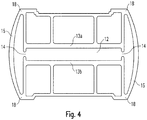
- the arcuate shape of the clamping portions 15 can be made as a radius of variable thickness. This increases the stability and the risk of buckling is reduced.
- This embodiment of the clamping portions 15 is disclosed as a design option in connection with all embodiments and is in Fig. 4 shown.
- the maximum thickness of the respective clamping section 15 is approximately equal to the side slit 14 and decreases on both sides towards the points of attack 18, where in each case the minimum thickness is present.
- the arrangement of the two engagement points 18 each of a clamping element 15 on both sides of the side slit 14 means that the engagement points 18 are arranged above and below the side slit 14 and spaced from the side slit 14.
- the side walls 19 of the flat housing 11 are, as stated, arranged perpendicular to the heating shaft 12 and extend between the side slot 14 and the engagement points 18 and the end points of the respective clamping portion 15. As in Fig. 1 can be seen, the side walls 19 are connected on its outer side with the end points of the clamping portions 15 in the region of the engagement points 18. On the inside of the clamping portions 15, the transition from the side walls 19 to the respective clamping portion 15 is formed with a rounding, in particular an ideal rounding, in order to keep the notch effect as minimal as possible.
- the side walls 19 are extended beyond the inner surfaces of the shaft walls 13a, 13b and project beyond these or the inner edges 21 formed there, thereby forming guide lugs 20.
- the guide lugs 20 bound the side slots 14.
- the guide lugs 20 form lateral stops for the in the heating shaft 12 arranged heating element, whereby the assembly of the heating element facilitates and a mechanical barrier against lateral slippage is formed.
- the cooling and holding body according to Fig. 1 has a single centrally disposed heating shaft 12.
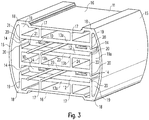
- the invention is not limited to such cooling and holding body, but also includes cooling and holding body with a plurality of heating ducts, as exemplified by the embodiments according to Fig. 2 . 3 is shown.
- a flat housing 11 which has straight outer walls 16. Laterally, the flat housing 11 is bounded by side walls 19 which extend perpendicular to the outer walls 16.
- the side walls 19 are in the embodiment according to Fig. 2 as well as in the embodiment according to Fig. 1 arranged within the convexly curved clamping portions 15 which engage over the side walls 19 on the outside of the flat housing 11.
- the flat housing according to Fig. 2 is on the outside of the outer shaft walls 13a, so in the space between the outer shaft walls 13a and the respective associated outer wall 16 similar to the embodiment according to Fig. 1 constructed and has transverse webs 17 which connect the outer shaft walls 13 a with the associated outer walls 16.
- transverse webs 17 For the function and arrangement of the transverse webs 17 is in accordance with the statements Fig. 1 directed.
- the two outer walls 16 are each offset inwards.
- the outer wall 16 forms a shoulder which runs parallel to the offset region of the respective outer wall 16 and forms the outer edge of the flat housing 11.
- the shoulder goes over into the clamping sections 15.
- a core 22 is provided which is arranged between the two outer shaft walls 13a and divides the flat housing 11 into two heating ducts 12 arranged one above the other in parallel.
- the core 22 has a rectangular cross section whose width corresponds to the width of the outer shaft walls 13a.
- the side walls 19a of the core 22 perpendicular to the inner shaft walls 13b are aligned with the side walls 19 connected to the outer shaft walls 13a.
- the sidewalls 19 connected to the outer shaft walls 13a and the side walls 19a of the core 22 form the (inner) straight sidewalls of the flat housing, which are bridged by the curved clamping sections 15.
- the two Schumanchte 12 are each in principle as the central heating shaft 12 according to Fig. 1 built and work accordingly.
- the two heating ducts 12 according to Fig. 2 each have two side slots 14, which decouple the core 22 and the inner shaft walls 13b of the outer shaft walls 13a. For a change in distance or broadening of the heating shaft is possible.
- For details and to the operation of the side slits 14 is based on the embodiments, for example according to Fig. 1 directed.
- the contact pressure is determined by the in Fig. 2 shown clamping portions 15 applied.
- the individual clamping sections 15 correspond in shape and arrangement to the clamping section 15 Fig. 1 , Reference is made to the corresponding statements.
- each heating shaft 12 on both sides clamping sections 15 are assigned.
- four clamping sections 15 are provided, two on each side of the flat housing 11.
- the function of the clamping sections corresponds to the function of the clamping sections according to Fig. 1 ,
- the clamping portions 15 on the one hand with the outer edge of the flat housing or generally connected to the flat housing 11 and on the other hand to the core 22, in particular integrally connected or formed in one piece.
- the clamping portions 15 engage in the center of the core 22 on the side surfaces 19 a.
- the transition between the side surface 19, 19 a of the flat housing 11 and the core 22 to the respective clamping portions 15 is carried out in each case with a rounding.
- the SchuMchte 12 each have guide lugs 20, as in the embodiment according to Fig. 1 are formed.
- the number of heating shafts according to Fig. 2 is to be understood as an example. It is also possible to provide more than two heating ducts with a corresponding number of cores and associated clamping sections, which are constructed on the same principle as in Fig. 2 shown. For a multiple stacking of heating elements in the height direction of the cooling and holding body and a corresponding increase in heating capacity is possible.
- the core 22 has transverse webs 24 which connect the outer walls 23 and the two inner shaft walls 13b and extend in the longitudinal direction of the core.
- the transverse webs 24 increase the strength of the core 22.
- the transverse webs 24 serve as cooling ribs in order to separate the heating elements from the heating element inner duct walls 13b dissipate transferred heat through an enlarged surface.
- two transverse webs 24 are provided, which run parallel to the side walls 19a. Another number, for example, only a single crossbar or more than two transverse webs are possible.
- the two heating elements 10 are shown in the assembled state, wherein these are arranged in a press fit in the heating shaft 12. Thereby, the above-described elastic deformation of the four or the plurality of clamping portions 15 is achieved and the associated contact pressure achieved.
- the heating elements are PTC heating elements, of which the ceramic base 10a in FIG Fig. 2 can be seen as well as the connecting wires 10b. Other electrical heating elements can be used.
- the heating elements 10 are electrically insulated from the heating shaft 12 by suitable insulating materials. This applies to all embodiments of this application.
- the difference between the versions according to Fig. 2 . 3 consists in the arrangement of the core 22 and the formation of the clamping portions 15.
- the core 22 according to Fig. 3 it is a so-called flying or floating core, which is arranged freely in the flat housing 11.
- the housing is Patschalig, concretely bivalve and has at least one core 22 and an outer shell.
- the core 22 is not directly, that is not materially connected to the flat housing 11.
- the fixation of the core 22 in the flat housing 11 is effected by the force exerted by the clamping portions 15 contact forces, which compress the heating elements and the core 22 arranged therebetween.
- the difference with respect to the clamping portions 15 is that the two Schwarzing section 12 on each side of the flat housing, a single clamping section 15 is associated.
- the clamping portion 15 thus overlaps both side slots 14 and generally more, in particular all side slots 14 on the same side of the housing.
- the common clamping portion 15 is attached to the two outer edges of the flat housing 11 and corresponds to the embodiment according to Fig. 1 ,
- the execution according to Fig. 3 has the advantage that this comparatively simple, for example by extrusion can be produced.
- the assembly forces for expansion of the flat housing 11 are applied in opposite directions at both clamping portions 15 such that the convexly curved clamping portions 15 are flattened, so that the outer shaft walls 13a are moved apart , The radius of the clamping portions 15 is increased.
- For fixing is - after the core 22 is introduced with the two heating elements 10 in the flared flat housing 11 - repealed the assembly force. Due to the excess of the heating elements 10 in the height direction, the clamping portions 15 can not return to the starting position, but remain elastically deformed, whereby the required contact pressure is applied.
- the core 22 and the outer shell or the flat housing 11 may be constructed of different combinations of materials with different or equal expansion coefficients in order to achieve a constant contact pressure.
- Fig. 5 . 6 show two embodiments in which the heating shaft 12, specifically the suspension of the shaft walls 13a, 13b is modified to increase the travel. This has the advantage that tolerances can be better compensated.
- each shaft wall 13a, 13b connected on one side with the flat housing 11.
- first longitudinal edge 25a of a shaft wall 13a, 13b is connected to the flat housing 11.
- second longitudinal edge 25b of the shaft wall 13a, 13b is free.
- the second longitudinal edge 25b is not connected to the flat housing 11, but movable relative to the flat housing 11.
- Both shaft walls 13a, 13b are fastened correspondingly to the flat housing 11, wherein the free longitudinal edges 25b of the shaft walls 13a, 13b are arranged on opposite sides.
- the side slit 14 is covered on both sides in each case by a side wall 19 of the flat housing 11.
- the free longitudinal edge 25b is spaced from the side wall 19, so that a movement of the free longitudinal edge 25b along the side wall 19 is unhindered possible.
- the clamping portions 15 engage the foot of the respective side wall 19.
- the foot opposite the end 26 of the respective side wall 19 is free.
- the free ends 26 of the side walls 19 are arranged offset on opposite sides of the housing or diagonally.
- the clamping portions 15 each engage over the side slot 14 and the free end 26 of the respective side wall 19 and are connected on the opposite side of the housing with the foot of the other side wall 19.
- the clamping portions 15 go in the region of the free ends 26 of the side walls 19, without touching them, in the respective straight outer wall 16 of the flat housing over.
- the distance between the free end 26 of the side wall 19 and the cross-part of the clamping portion 15 is dimensioned so that a sufficient spring travel is possible.
- the deformation of the clamping portions 15 takes place below the elastic limit, so that in the operating state with clamped heating element 10, the spring force due to the elastic deformation is generated according to the respective material constant.
- cooling fins 27 are provided on the outside of the shaft walls.
- the side wall 19 projects beyond the associated shaft wall 13a, 13b and also forms a cooling rib 27.
- Other forms of cooling fins are possible.
- clamping portions 15 which according to FIG. 6 is arrow-shaped.
- clamping portions 15 together with the respectively associated side wall 19 form an approximately triangular cross-sectional profile with a straight leg 28, wherein a tip of the triangular cross-sectional profile is opened.
- the open tip corresponds to the free end 26 of the respective side wall 19.
- the cooling and holding body according to Fig. 7 is in the basic structure similar to the cooling and holding body according to Fig. 5 . 6 educated.
- the two shaft walls 13a, 13b are as in Fig. 5 . 6 in the region of the first longitudinal edge 25a in each case connected to the flat housing 11 such that the movement of the shaft walls 13a, 13b for installation in the region of the first longitudinal edges 25a through the flat housing 11, in particular through the respective clamping portions 15 of the flat housing 11 is introduced.
- the first longitudinal edges 25a of the two shaft walls 13a, 13b are each connected to the flat housing 11 on opposite sides.
- the first longitudinal edges 25a are located diagonally opposite. The same applies to the position of the second free longitudinal edges 25b.
- the embodiments correspond according to Fig. 5 . 6 . 7 , With regard to the basic structure according to Fig. 7 will apply to the comments Fig. 5 . 6 Referenced.
- the difference between the embodiment according to Fig. 7 and the examples according to Fig. 5 . 6 consists in that the two shaft walls 13a, 13b are each connected to a stiffening rib 29.
- the stiffening rib 29 engages on the outside of the respective shaft wall 13a, 13b, ie on the side facing away from the heating shaft 12 side of the respective shaft wall 13a, 13b.
- the point of application or the line of attack of the stiffening rib 29 is located in each case between the first and second longitudinal edges 25a, 25b of the respective shaft wall 13a, 13b.
- the longitudinal rib 29 is connected to the flat housing 11 in the region of the first longitudinal edge 25a of the associated shaft wall 13a, 13b.
- the longitudinal rib 29 forms an extension of the respective side wall 19 of the flat housing.
- the side wall 19 is beveled above the first longitudinal edge 25a and forms a parallel to the outer wall 16 extending web 30a.
- the parallel web 30a thus extends between the outer wall 16 and the associated shaft wall 13a, 13b.
- the parallel web 30a is bent and merges into a transverse web 30b, which is connected to the outside of the shaft wall 13a, 13b.
- the stiffening rib 29 extends as in FIG Fig. 7 seen, in the longitudinal direction of the flat housing 11 and over the entire axial length of the flat housing eleventh
- each shaft wall 13a, 13b is connected to the flat housing 11 at two locations.
- the contact pressure is also comparable.
- the connection of a shaft wall 13a, 13b to the flat housing 11 takes place on one and the same side of the respective shaft wall 13a, 13b. This means that in the first shaft wall 13a, the first longitudinal edge 25a and the reinforcing rib 29 on the same side are connected to the flat housing 11, specifically to the side wall 19 of the flat housing 11. This ensures that the transmitted by the side wall 19 movement or contact force in one and the same shaft wall 13a, 13b is initiated.
- the contact force acting in opposite directions is generally achieved by the nested arrangement of the clamping surfaces 15 and the shaft walls 13a, 13b.
- the nested arrangement means that the attack sites, at where the clamping portions 15 are connected to the flat housing 11, are arranged at diagonal corners of the flat housing 11. Accordingly, the free ends 26 of the side walls 19 are arranged at diagonally opposite corners of the flat housing.
- the diagonal arrangement of the points of attack of the clamping portions 15 and the free ends 26 is achieved that at an increase in the radius of the clamping portions 15, for example, by applying a mounting force, the attack points at which the clamping portions 15 are connected to the flat housing 11, pressed apart.
- each stiffening chambers 31 are provided in the lower region of the side walls 19, which also improve the heat transfer through the enlarged area.
- the stiffening chambers 31 are respectively provided at the foot end of the side walls 19, that is, in the region in which the clamping portions 19 are connected to the flat housing 11.
- the transitions of the clamping portions 15 to the flat housing 11 and to the side walls 19 curves on to reduce the notch effect. This ensures that even in the area of the transitions the deformation is below the elastic limit, ie in the area of Hooke's straight line.
Landscapes
- Resistance Heating (AREA)
- Air-Conditioning For Vehicles (AREA)
- Direct Air Heating By Heater Or Combustion Gas (AREA)
- Secondary Cells (AREA)
Priority Applications (1)
| Application Number | Priority Date | Filing Date | Title |
|---|---|---|---|
| PL12787386T PL2772116T3 (pl) | 2011-10-24 | 2012-10-22 | Układ chłodzący i mocujący dla elementów grzewczych, urządzenie grzewcze i sposób wytwarzania układu chłodzącego i mocującego |
Applications Claiming Priority (2)
| Application Number | Priority Date | Filing Date | Title |
|---|---|---|---|
| DE102011054752.5A DE102011054752B4 (de) | 2011-10-24 | 2011-10-24 | Kühl- und Haltekörper für Heizelemente, Heizgerät und Verfahren zur Herstellung eines Kühl- und Haltekörpers |
| PCT/EP2012/070871 WO2013060647A1 (de) | 2011-10-24 | 2012-10-22 | Kühl- und haltekörper für heizelemente, heizgerät und verfahren zur herstellung eines kühl- und haltekörpers |
Publications (2)
| Publication Number | Publication Date |
|---|---|
| EP2772116A1 EP2772116A1 (de) | 2014-09-03 |
| EP2772116B1 true EP2772116B1 (de) | 2018-01-17 |
Family
ID=47189889
Family Applications (1)
| Application Number | Title | Priority Date | Filing Date |
|---|---|---|---|
| EP12787386.7A Active EP2772116B1 (de) | 2011-10-24 | 2012-10-22 | Kühl- und haltekörper für heizelemente, heizgerät und verfahren zur herstellung eines kühl- und haltekörpers |
Country Status (12)
| Country | Link |
|---|---|
| US (1) | US9661689B2 (enExample) |
| EP (1) | EP2772116B1 (enExample) |
| JP (1) | JP6075801B2 (enExample) |
| CN (1) | CN103891399B (enExample) |
| BR (1) | BR112014009640A2 (enExample) |
| DE (1) | DE102011054752B4 (enExample) |
| ES (1) | ES2665304T3 (enExample) |
| IN (1) | IN2014CN02579A (enExample) |
| PL (1) | PL2772116T3 (enExample) |
| RU (1) | RU2599530C2 (enExample) |
| TW (1) | TWI606777B (enExample) |
| WO (1) | WO2013060647A1 (enExample) |
Families Citing this family (14)
| Publication number | Priority date | Publication date | Assignee | Title |
|---|---|---|---|---|
| KR200486211Y1 (ko) * | 2015-12-21 | 2018-04-16 | 자화전자(주) | 피티씨 히터 |
| KR101711030B1 (ko) * | 2015-12-24 | 2017-03-02 | (주)하이엘 | 피티씨 히터 |
| CN106376106B (zh) * | 2016-10-24 | 2023-01-03 | 美的集团武汉制冷设备有限公司 | 空调室内机的ptc电加热器及空调室内机 |
| JP6769331B2 (ja) * | 2017-02-15 | 2020-10-14 | 株式会社デンソー | ワーク保持部材、及びそれを用いるワーク回転装置 |
| DE102017121042A1 (de) * | 2017-05-24 | 2018-11-29 | Webasto SE | Flüssigkeitsheizgerät, insbesondere Wasserheizgerät |
| US11118810B2 (en) | 2017-10-19 | 2021-09-14 | Tom Richards, Inc. | Heat transfer assembly |
| DE102019108435B4 (de) * | 2019-04-01 | 2025-02-06 | Borgwarner Ludwigsburg Gmbh | Verfahren zum Herstellen eines Heizstabs |
| EP3945747A1 (en) * | 2020-07-26 | 2022-02-02 | Valeo Klimasysteme GmbH | A tube for an electric heater |
| DE102021104680A1 (de) * | 2021-02-26 | 2022-09-01 | Eberspächer Catem Gmbh & Co. Kg | Elektrische Heizvorrichtung |
| DE102021106299A1 (de) | 2021-03-16 | 2022-09-22 | Eberspächer Catem Gmbh & Co. Kg | Elektrische Heizvorrichtung |
| USD1038348S1 (en) | 2021-05-05 | 2024-08-06 | Stego-Holding Gmbh | Convector heater |
| USD1030014S1 (en) | 2021-05-05 | 2024-06-04 | Stego-Holding Gmbh | Convector heater |
| DE102021111665B4 (de) | 2021-05-05 | 2022-12-01 | Stego-Holding Gmbh | Haltevorrichtung, Heizgerät und Verfahren |
| USD1030013S1 (en) | 2021-08-17 | 2024-06-04 | Stego-Holding Gmbh | Convector heater |
Citations (4)
| Publication number | Priority date | Publication date | Assignee | Title |
|---|---|---|---|---|
| DE2804818A1 (de) * | 1978-02-04 | 1979-08-09 | Eichenauer Fa Fritz | Elektrische widerstandsheizeinrichtung |
| DE4010620A1 (de) * | 1990-04-02 | 1991-10-10 | Petz Elektro Waerme Techn | Elektrisches heizelement |
| DE20120281U1 (de) * | 2001-12-14 | 2002-04-04 | Weda-Dammann & Westerkamp GmbH, 49424 Goldenstedt | Futteranmischbehälter |
| EP2053902A1 (en) * | 2007-10-26 | 2009-04-29 | Calsonic Kansei Corporation | Electrical heating apparatus, method of manufacturing heat generator unit and pressing jig for use in manufacturing thereof |
Family Cites Families (74)
| Publication number | Priority date | Publication date | Assignee | Title |
|---|---|---|---|---|
| US3146519A (en) | 1961-03-21 | 1964-09-01 | Etc Inc | Method of making electrical connections |
| US3108174A (en) | 1962-06-27 | 1963-10-22 | Hynes Electric Heating Co | Heavy duty heaters for gases |
| US3662149A (en) | 1969-09-16 | 1972-05-09 | Braun Pebra Gmbh | Heated lock for motorcars |
| US3996447A (en) * | 1974-11-29 | 1976-12-07 | Texas Instruments Incorporated | PTC resistance heater |
| US4021098A (en) | 1975-09-04 | 1977-05-03 | International Telephone And Telegraph Corporation | Fiber bundle consolidation |
| DE2804749C3 (de) | 1978-02-04 | 1980-07-31 | Fa. Fritz Eichenauer, 6744 Kandel | Durchlauferhitzer |
| DE2905905A1 (de) * | 1978-02-22 | 1979-08-23 | Tdk Electronics Co Ltd | Wabenfoermiges heizelement |
| JPS6054730B2 (ja) | 1978-03-02 | 1985-12-02 | 日本碍子株式会社 | 合成樹脂碍子 |
| JPS5561688U (enExample) | 1978-10-20 | 1980-04-26 | ||
| DE2902909A1 (de) | 1979-01-26 | 1980-07-31 | Eichenauer Fa Fritz | Schaltschrank-heizgeraet |
| US4673801A (en) | 1979-08-17 | 1987-06-16 | Raychem Corporation | PTC heater assembly |
| DE2939470C2 (de) * | 1979-09-28 | 1982-04-08 | Siemens AG, 1000 Berlin und 8000 München | Kaltleiter-Heizeinrichtung |
| DE7934523U1 (de) * | 1979-12-07 | 1980-03-20 | Siemens Ag, 1000 Berlin Und 8000 Muenchen | Durchlauferhitzer mit heizwiderstaenden aus kaltleitendem keramischen material |
| US4431983A (en) * | 1980-08-29 | 1984-02-14 | Sprague Electric Company | PTCR Package |
| US4425692A (en) | 1981-03-23 | 1984-01-17 | Jidosha Kiki Co., Ltd. | Glow plug for use in diesel engine and method of manufacturing the same |
| GB2143708B (en) | 1983-06-23 | 1986-12-17 | Tokai Electric Wire | Heating device for heating an air-fuel mixture to be supplied to an internal combustion engine |
| US4578235A (en) * | 1983-08-01 | 1986-03-25 | Hawkeye Concrete Products Co. | Method for lining pipe |
| JPS6048201U (ja) * | 1983-09-09 | 1985-04-04 | ティーディーケイ株式会社 | 正特性サ−ミスタ装置 |
| DE3621241C1 (de) * | 1986-06-25 | 1987-06-25 | Freudenberg Carl Fa | Verfahren zur Herstellung eines Dichtringes mit einer Dichtlippe |
| EP0262243B1 (de) | 1986-10-01 | 1991-02-20 | David & Baader DBK Spezialfabrik elektrischer Apparate und Heizwiderstände GmbH | Kaltleiter-PTC-Heizkörper |
| US5166497A (en) | 1986-12-16 | 1992-11-24 | Raychem Gmbh | Facade heating |
| DE3852519T2 (de) * | 1987-04-21 | 1995-08-10 | Fumakilla Ltd | Heizvorrichtung mit Kaltleiter. |
| US4822980A (en) | 1987-05-04 | 1989-04-18 | Gte Products Corporation | PTC heater device |
| US4870249A (en) | 1987-05-26 | 1989-09-26 | Texas Instruments Incorporated | Electric fuel heating device |
| JPH0734390B2 (ja) | 1987-09-11 | 1995-04-12 | 株式会社村田製作所 | 正特性サーミスタ装置 |
| US4855570A (en) | 1987-12-09 | 1989-08-08 | Tim Wang | Electric fluid heating unit having radial PTC ceramic heating elements |
| US4855571A (en) | 1988-01-29 | 1989-08-08 | Industrial Technology Research Institute | Positive temperature coefficient ceramic heating element for heating a fluid |
| JP2556877B2 (ja) | 1988-03-10 | 1996-11-27 | 株式会社村田製作所 | 正特性サーミスタ装置 |
| DE3815306A1 (de) * | 1988-05-05 | 1989-11-16 | Eichenauer Gmbh & Co Kg F | Elektrisches heizelement mit ptc-element |
| DE3816819A1 (de) | 1988-05-18 | 1989-11-30 | Stettner & Co | Heizvorrichtung mit ptc-elementen |
| US5111032A (en) | 1989-03-13 | 1992-05-05 | Raychem Corporation | Method of making an electrical device comprising a conductive polymer |
| US5204044A (en) | 1989-03-28 | 1993-04-20 | Aisan Kogyo Kabushiki Kaisha | Method of asembling a DC solenoid with a thermistor |
| US5125070A (en) | 1989-07-11 | 1992-06-23 | Chung Tai Chang | PTC heater assembly with securely positioned PTC resistors |
| US5153555A (en) * | 1989-11-28 | 1992-10-06 | Murata Manufacturing Co., Ltd. | Electronic device comprising a plate-shaped electronic element and a support and overcurrent protector for the same |
| US5198640A (en) * | 1991-05-28 | 1993-03-30 | Yang Chiung Hsiang | Fully clad electric ptc heater with a finned protective casing |
| US5201774A (en) * | 1991-08-23 | 1993-04-13 | United States Manufacturing Company | Prosthetic valve system and process for sealing a socket |
| US5192853A (en) | 1991-10-22 | 1993-03-09 | Yeh Yuan Chang | Heating set having positive temperatue coefficient thermistor elements adhesively connected to heat radiator devices |
| JPH07335408A (ja) * | 1994-06-10 | 1995-12-22 | Murata Mfg Co Ltd | 発熱電子部品 |
| US5471029A (en) | 1994-07-22 | 1995-11-28 | Tuffaloy Products, Inc. | Water cooled resistance welding assembly |
| US6318864B1 (en) | 1994-11-15 | 2001-11-20 | Olympus Optical Co., Ltd. | Sterile instruments cover for use on surgical microscopes |
| DE19521755C1 (de) | 1995-06-14 | 1996-10-02 | Schunk Fritz Gmbh | Verbindungssystem zum lösbaren festen Verbinden zweier Bauteile |
| DE19604218C2 (de) | 1996-02-06 | 1998-03-26 | Loh Kg Rittal Werk | Heizgerät mit einem PTC-Element und einem Profilkontaktkörper |
| JPH10220909A (ja) | 1996-12-03 | 1998-08-21 | Komatsu Ltd | 流体温度制御装置 |
| DE29720357U1 (de) * | 1997-01-17 | 1998-02-26 | Siemens Matsushita Components GmbH & Co. KG, 81541 München | Kaltleiteranordnung |
| US5922231A (en) | 1997-05-13 | 1999-07-13 | Dekko Heating Technologies, Inc. | Voltage surge resistant positive temperature coefficient heater |
| US6054692A (en) | 1997-06-25 | 2000-04-25 | Takehiko Hitomi | Heating device, heat storing type heat generating body and protective sheet for the heating device |
| US6079716A (en) | 1997-12-12 | 2000-06-27 | Black & Decker Inc. | Removable chuck |
| JP3331561B2 (ja) | 1997-12-12 | 2002-10-07 | 矢崎総業株式会社 | 電線接続部の密封方法、及び熱収縮チューブの保持治具、並びに収縮機 |
| US6180930B1 (en) * | 1999-12-29 | 2001-01-30 | Chia-Hsiung Wu | Heater with enclosing envelope |
| DK1301304T3 (da) | 2000-07-14 | 2005-12-05 | Franz Haimer Maschb Kg | Værktöjsholder til et omkring en omdrejningsakse drejeligt værktöj, især et bore, fræse eller römmeværktöj |
| US6455822B1 (en) | 2000-10-11 | 2002-09-24 | Mega Dynamics Ltd. | Heat sink for a PTC heating element and a PTC heating member made thereof |
| RU24482U1 (ru) | 2001-09-12 | 2002-08-10 | Васильев Всеволод Дмитриевич | Ограждающая конструкция многоэтажного строения |
| US20030095795A1 (en) | 2001-11-21 | 2003-05-22 | Birdsell Walter G. | PTC heating element |
| DE20120821U1 (de) * | 2001-12-21 | 2002-05-08 | Türk & Hillinger GmbH, 78532 Tuttlingen | Elektrische Heizvorrichtung für Absorptionskühlsysteme |
| RU25582U1 (ru) | 2002-03-19 | 2002-10-10 | Гончаров Александр Викторович | Канальный электронагреватель воздуха |
| DE20216509U1 (de) * | 2002-10-22 | 2004-02-26 | Eichenauer Heizelemente Gmbh & Co. Kg | Elektrische Heizeinrichtung |
| DE10333678B4 (de) | 2003-07-24 | 2006-06-08 | Thyssenkrupp Steel Ag | Verfahren zum Herstellen eines abschnittweise verstärkten rohrförmigen Trägers aus Metall, insbesondere für Tragstrukturen in Kraftfahrzeugen |
| US7427341B2 (en) | 2003-08-15 | 2008-09-23 | Symyx Technologies, Inc. | System for synthesis of electrode array |
| DE10360159A1 (de) * | 2003-12-20 | 2005-07-21 | Eichenauer Heizelemente Gmbh & Co. Kg | Profilrohr und Verfahren zum Verspannen von Funktionselementen in einem solchen |
| PT1580495E (pt) | 2004-03-22 | 2011-12-15 | Halla Climate Control Corp | Aquecedor eléctrico |
| US20060024145A1 (en) | 2004-07-29 | 2006-02-02 | Pei-Chung Wang | Friction stir rivet and method of joining therewith |
| ATE357123T1 (de) | 2004-11-11 | 2007-04-15 | Dbk David & Baader Gmbh | Elektrischer platinenheizbaustein, elektronikplatine und verfahren zum beheizen |
| DE202005020765U1 (de) | 2005-08-10 | 2006-07-06 | Stego-Holding Gmbh | Vorrichtung zum Übertragen von Wärme von einem Heizelement auf Umgebungsluft |
| EP1963753B1 (de) | 2005-12-20 | 2016-06-08 | BorgWarner Ludwigsburg GmbH | Elektrische heizvorrichtung, insbesondere für automobile |
| JP4843356B2 (ja) | 2006-04-13 | 2011-12-21 | 昭和電工株式会社 | 部材同士の接合方法 |
| DE102006018151B4 (de) | 2006-04-19 | 2012-07-19 | Stego-Holding Gmbh | Heizgerät |
| DE102006018150B4 (de) * | 2006-04-19 | 2008-01-24 | Stego-Holding Gmbh | Heizeinrichtung |
| DE102006055216B4 (de) * | 2006-11-21 | 2012-11-15 | Eichenauer Heizelemente Gmbh & Co. Kg | Heizeinrichtung für Dieselkraftstoff und beheizbares Dieselfiltersystem |
| GB2451080B (en) * | 2007-07-17 | 2011-10-05 | Uponor Innovation Ab | Tapping tee assembly |
| DE102008030212A1 (de) | 2007-10-18 | 2009-04-23 | Stego-Holding Gmbh | Heizvorrichtung und Wärmetauscher |
| CA2756911C (en) | 2009-03-31 | 2017-08-29 | Alcoa Inc. | Electrode holder assembly and furnace comprising same |
| DE102010006184A1 (de) | 2010-01-29 | 2011-08-04 | Eichenauer Heizelemente GmbH & Co. KG, 76870 | Elektrische Heizeinrichtung und Verfahren zum Fertigen einer elektrischen Heizeinrichtung |
| EP2440004B1 (de) | 2010-10-08 | 2015-02-25 | Eberspächer catem GmbH & Co. KG | Elektrische Heizvorrichtung |
| EP2440005B1 (de) | 2010-10-08 | 2015-12-23 | Eberspächer catem GmbH & Co. KG | Elektrische Heizvorrichtung und Verfahren zur Herstellung |
-
2010
- 2010-08-18 IN IN2579CHN2014 patent/IN2014CN02579A/en unknown
-
2011
- 2011-10-24 DE DE102011054752.5A patent/DE102011054752B4/de not_active Expired - Fee Related
-
2012
- 2012-10-22 EP EP12787386.7A patent/EP2772116B1/de active Active
- 2012-10-22 US US14/354,006 patent/US9661689B2/en active Active
- 2012-10-22 RU RU2014120902/07A patent/RU2599530C2/ru active
- 2012-10-22 PL PL12787386T patent/PL2772116T3/pl unknown
- 2012-10-22 BR BR112014009640A patent/BR112014009640A2/pt not_active Application Discontinuation
- 2012-10-22 WO PCT/EP2012/070871 patent/WO2013060647A1/de not_active Ceased
- 2012-10-22 CN CN201280052012.8A patent/CN103891399B/zh active Active
- 2012-10-22 JP JP2014536280A patent/JP6075801B2/ja not_active Expired - Fee Related
- 2012-10-22 ES ES12787386.7T patent/ES2665304T3/es active Active
- 2012-10-23 TW TW101139054A patent/TWI606777B/zh not_active IP Right Cessation
Patent Citations (4)
| Publication number | Priority date | Publication date | Assignee | Title |
|---|---|---|---|---|
| DE2804818A1 (de) * | 1978-02-04 | 1979-08-09 | Eichenauer Fa Fritz | Elektrische widerstandsheizeinrichtung |
| DE4010620A1 (de) * | 1990-04-02 | 1991-10-10 | Petz Elektro Waerme Techn | Elektrisches heizelement |
| DE20120281U1 (de) * | 2001-12-14 | 2002-04-04 | Weda-Dammann & Westerkamp GmbH, 49424 Goldenstedt | Futteranmischbehälter |
| EP2053902A1 (en) * | 2007-10-26 | 2009-04-29 | Calsonic Kansei Corporation | Electrical heating apparatus, method of manufacturing heat generator unit and pressing jig for use in manufacturing thereof |
Also Published As
| Publication number | Publication date |
|---|---|
| CN103891399B (zh) | 2016-01-20 |
| CN103891399A (zh) | 2014-06-25 |
| TWI606777B (zh) | 2017-11-21 |
| DE102011054752A1 (de) | 2013-04-25 |
| ES2665304T3 (es) | 2018-04-25 |
| DE102011054752B4 (de) | 2014-09-04 |
| RU2014120902A (ru) | 2015-12-10 |
| RU2599530C2 (ru) | 2016-10-10 |
| JP2014534573A (ja) | 2014-12-18 |
| TW201325424A (zh) | 2013-06-16 |
| PL2772116T3 (pl) | 2018-07-31 |
| IN2014CN02579A (enExample) | 2015-06-26 |
| JP6075801B2 (ja) | 2017-02-08 |
| BR112014009640A2 (pt) | 2017-06-13 |
| US20140299293A1 (en) | 2014-10-09 |
| WO2013060647A1 (de) | 2013-05-02 |
| EP2772116A1 (de) | 2014-09-03 |
| US9661689B2 (en) | 2017-05-23 |
Similar Documents
| Publication | Publication Date | Title |
|---|---|---|
| DE102011054752B4 (de) | Kühl- und Haltekörper für Heizelemente, Heizgerät und Verfahren zur Herstellung eines Kühl- und Haltekörpers | |
| DE102011054750B4 (de) | Kühl- und Haltekörper für Heizelemente, Heizgerät und Verfahren zur Herstellung eines Kühl- und Haltekörpers | |
| EP1790916B1 (de) | Elektrische Heizvorrichtung mit Toleranz-PTC-Heizelement | |
| EP1515587B1 (de) | Elektrische Heizvorrichtung mit versiegeltem Heizelement | |
| DE102009033370B4 (de) | Stromschiene mit Kompensationsabschnitt | |
| DE202009009607U1 (de) | Stromschiene mit Kompensationsabschnitt | |
| DE102005031504A1 (de) | Prismatische Batterie aus mehreren Einzelzellen | |
| DE102007006058A1 (de) | Elektrisches Heizmodul zur Luftstromerwärmung, insbesondere zur Heizung und Belüftung von Sitzen | |
| DE202014103206U1 (de) | Wärmeaustauscher | |
| DE102020119350A1 (de) | Leiteranschlussklemme | |
| DE102010062240A1 (de) | Multiphasenwandler | |
| EP4044780B1 (de) | Elektrogerät mit gehäuseteil | |
| DE102010033310A1 (de) | Elektrisches Heizmodul mit PTC-Element zum elektrischen Erwärmen eines Luftstroms | |
| DE202010011016U1 (de) | Elektrisches Heizmodul mit PTC-Element zum elektrischen Erwärmen eines Luftstroms | |
| DE102006018151B4 (de) | Heizgerät | |
| DE102016210159A1 (de) | Rippenelement für einen Wärmeübertrager | |
| DE102019116362A1 (de) | Filterbauelement und Anordnung zur Befestigung eines Filterbauelements | |
| EP4335245B1 (de) | Haltevorrichtung, heizgerät und verfahren | |
| DE19732010A1 (de) | Elektrische Heizeinrichtung, insbesondere für ein Kraftfahrzeug | |
| WO2006105925A1 (de) | Wärmeübertrager, insbesondere für ein kraftfahrzeug | |
| DE102005043291A1 (de) | Seitenblech für Kühler | |
| DE102022112414A1 (de) | Flexibler Modulverbinder für eine Batterie und Batterie für ein Kraftfahrzeug | |
| DE2500223C3 (de) | Elektrisches Widerstandsgerät | |
| EP3261118A1 (de) | Kühlkörper | |
| DE102018213676A1 (de) | Wärmeübertrager für ein Kraftfahrzeug und ein Verfahren zum Herstellen des Wärmeübertragers |
Legal Events
| Date | Code | Title | Description |
|---|---|---|---|
| PUAI | Public reference made under article 153(3) epc to a published international application that has entered the european phase |
Free format text: ORIGINAL CODE: 0009012 |
|
| 17P | Request for examination filed |
Effective date: 20140328 |
|
| AK | Designated contracting states |
Kind code of ref document: A1 Designated state(s): AL AT BE BG CH CY CZ DE DK EE ES FI FR GB GR HR HU IE IS IT LI LT LU LV MC MK MT NL NO PL PT RO RS SE SI SK SM TR |
|
| DAX | Request for extension of the european patent (deleted) | ||
| 17Q | First examination report despatched |
Effective date: 20161219 |
|
| GRAP | Despatch of communication of intention to grant a patent |
Free format text: ORIGINAL CODE: EPIDOSNIGR1 |
|
| INTG | Intention to grant announced |
Effective date: 20170802 |
|
| GRAS | Grant fee paid |
Free format text: ORIGINAL CODE: EPIDOSNIGR3 |
|
| GRAA | (expected) grant |
Free format text: ORIGINAL CODE: 0009210 |
|
| AK | Designated contracting states |
Kind code of ref document: B1 Designated state(s): AL AT BE BG CH CY CZ DE DK EE ES FI FR GB GR HR HU IE IS IT LI LT LU LV MC MK MT NL NO PL PT RO RS SE SI SK SM TR |
|
| REG | Reference to a national code |
Ref country code: GB Ref legal event code: FG4D Free format text: NOT ENGLISH |
|
| REG | Reference to a national code |
Ref country code: CH Ref legal event code: EP |
|
| REG | Reference to a national code |
Ref country code: IE Ref legal event code: FG4D Free format text: LANGUAGE OF EP DOCUMENT: GERMAN |
|
| REG | Reference to a national code |
Ref country code: AT Ref legal event code: REF Ref document number: 965223 Country of ref document: AT Kind code of ref document: T Effective date: 20180215 |
|
| REG | Reference to a national code |
Ref country code: DE Ref legal event code: R096 Ref document number: 502012012040 Country of ref document: DE |
|
| REG | Reference to a national code |
Ref country code: SE Ref legal event code: TRGR |
|
| REG | Reference to a national code |
Ref country code: NL Ref legal event code: FP |
|
| REG | Reference to a national code |
Ref country code: ES Ref legal event code: FG2A Ref document number: 2665304 Country of ref document: ES Kind code of ref document: T3 Effective date: 20180425 |
|
| REG | Reference to a national code |
Ref country code: LT Ref legal event code: MG4D |
|
| PG25 | Lapsed in a contracting state [announced via postgrant information from national office to epo] |
Ref country code: CY Free format text: LAPSE BECAUSE OF FAILURE TO SUBMIT A TRANSLATION OF THE DESCRIPTION OR TO PAY THE FEE WITHIN THE PRESCRIBED TIME-LIMIT Effective date: 20180117 Ref country code: LT Free format text: LAPSE BECAUSE OF FAILURE TO SUBMIT A TRANSLATION OF THE DESCRIPTION OR TO PAY THE FEE WITHIN THE PRESCRIBED TIME-LIMIT Effective date: 20180117 Ref country code: HR Free format text: LAPSE BECAUSE OF FAILURE TO SUBMIT A TRANSLATION OF THE DESCRIPTION OR TO PAY THE FEE WITHIN THE PRESCRIBED TIME-LIMIT Effective date: 20180117 Ref country code: FI Free format text: LAPSE BECAUSE OF FAILURE TO SUBMIT A TRANSLATION OF THE DESCRIPTION OR TO PAY THE FEE WITHIN THE PRESCRIBED TIME-LIMIT Effective date: 20180117 Ref country code: NO Free format text: LAPSE BECAUSE OF FAILURE TO SUBMIT A TRANSLATION OF THE DESCRIPTION OR TO PAY THE FEE WITHIN THE PRESCRIBED TIME-LIMIT Effective date: 20180417 |
|
| PG25 | Lapsed in a contracting state [announced via postgrant information from national office to epo] |
Ref country code: RS Free format text: LAPSE BECAUSE OF FAILURE TO SUBMIT A TRANSLATION OF THE DESCRIPTION OR TO PAY THE FEE WITHIN THE PRESCRIBED TIME-LIMIT Effective date: 20180117 Ref country code: BG Free format text: LAPSE BECAUSE OF FAILURE TO SUBMIT A TRANSLATION OF THE DESCRIPTION OR TO PAY THE FEE WITHIN THE PRESCRIBED TIME-LIMIT Effective date: 20180417 Ref country code: GR Free format text: LAPSE BECAUSE OF FAILURE TO SUBMIT A TRANSLATION OF THE DESCRIPTION OR TO PAY THE FEE WITHIN THE PRESCRIBED TIME-LIMIT Effective date: 20180418 Ref country code: IS Free format text: LAPSE BECAUSE OF FAILURE TO SUBMIT A TRANSLATION OF THE DESCRIPTION OR TO PAY THE FEE WITHIN THE PRESCRIBED TIME-LIMIT Effective date: 20180517 Ref country code: LV Free format text: LAPSE BECAUSE OF FAILURE TO SUBMIT A TRANSLATION OF THE DESCRIPTION OR TO PAY THE FEE WITHIN THE PRESCRIBED TIME-LIMIT Effective date: 20180117 |
|
| PG25 | Lapsed in a contracting state [announced via postgrant information from national office to epo] |
Ref country code: MT Free format text: LAPSE BECAUSE OF FAILURE TO SUBMIT A TRANSLATION OF THE DESCRIPTION OR TO PAY THE FEE WITHIN THE PRESCRIBED TIME-LIMIT Effective date: 20180117 |
|
| REG | Reference to a national code |
Ref country code: DE Ref legal event code: R097 Ref document number: 502012012040 Country of ref document: DE |
|
| REG | Reference to a national code |
Ref country code: FR Ref legal event code: PLFP Year of fee payment: 7 |
|
| PG25 | Lapsed in a contracting state [announced via postgrant information from national office to epo] |
Ref country code: AL Free format text: LAPSE BECAUSE OF FAILURE TO SUBMIT A TRANSLATION OF THE DESCRIPTION OR TO PAY THE FEE WITHIN THE PRESCRIBED TIME-LIMIT Effective date: 20180117 Ref country code: RO Free format text: LAPSE BECAUSE OF FAILURE TO SUBMIT A TRANSLATION OF THE DESCRIPTION OR TO PAY THE FEE WITHIN THE PRESCRIBED TIME-LIMIT Effective date: 20180117 Ref country code: EE Free format text: LAPSE BECAUSE OF FAILURE TO SUBMIT A TRANSLATION OF THE DESCRIPTION OR TO PAY THE FEE WITHIN THE PRESCRIBED TIME-LIMIT Effective date: 20180117 |
|
| PLBE | No opposition filed within time limit |
Free format text: ORIGINAL CODE: 0009261 |
|
| STAA | Information on the status of an ep patent application or granted ep patent |
Free format text: STATUS: NO OPPOSITION FILED WITHIN TIME LIMIT |
|
| PG25 | Lapsed in a contracting state [announced via postgrant information from national office to epo] |
Ref country code: SK Free format text: LAPSE BECAUSE OF FAILURE TO SUBMIT A TRANSLATION OF THE DESCRIPTION OR TO PAY THE FEE WITHIN THE PRESCRIBED TIME-LIMIT Effective date: 20180117 Ref country code: SM Free format text: LAPSE BECAUSE OF FAILURE TO SUBMIT A TRANSLATION OF THE DESCRIPTION OR TO PAY THE FEE WITHIN THE PRESCRIBED TIME-LIMIT Effective date: 20180117 Ref country code: DK Free format text: LAPSE BECAUSE OF FAILURE TO SUBMIT A TRANSLATION OF THE DESCRIPTION OR TO PAY THE FEE WITHIN THE PRESCRIBED TIME-LIMIT Effective date: 20180117 |
|
| 26N | No opposition filed |
Effective date: 20181018 |
|
| PG25 | Lapsed in a contracting state [announced via postgrant information from national office to epo] |
Ref country code: SI Free format text: LAPSE BECAUSE OF FAILURE TO SUBMIT A TRANSLATION OF THE DESCRIPTION OR TO PAY THE FEE WITHIN THE PRESCRIBED TIME-LIMIT Effective date: 20180117 |
|
| REG | Reference to a national code |
Ref country code: CH Ref legal event code: PL |
|
| REG | Reference to a national code |
Ref country code: BE Ref legal event code: MM Effective date: 20181031 |
|
| PG25 | Lapsed in a contracting state [announced via postgrant information from national office to epo] |
Ref country code: MC Free format text: LAPSE BECAUSE OF FAILURE TO SUBMIT A TRANSLATION OF THE DESCRIPTION OR TO PAY THE FEE WITHIN THE PRESCRIBED TIME-LIMIT Effective date: 20180117 Ref country code: LU Free format text: LAPSE BECAUSE OF NON-PAYMENT OF DUE FEES Effective date: 20181022 |
|
| REG | Reference to a national code |
Ref country code: IE Ref legal event code: MM4A |
|
| PG25 | Lapsed in a contracting state [announced via postgrant information from national office to epo] |
Ref country code: BE Free format text: LAPSE BECAUSE OF NON-PAYMENT OF DUE FEES Effective date: 20181031 Ref country code: CH Free format text: LAPSE BECAUSE OF NON-PAYMENT OF DUE FEES Effective date: 20181031 Ref country code: LI Free format text: LAPSE BECAUSE OF NON-PAYMENT OF DUE FEES Effective date: 20181031 |
|
| PG25 | Lapsed in a contracting state [announced via postgrant information from national office to epo] |
Ref country code: IE Free format text: LAPSE BECAUSE OF NON-PAYMENT OF DUE FEES Effective date: 20181022 |
|
| REG | Reference to a national code |
Ref country code: AT Ref legal event code: MM01 Ref document number: 965223 Country of ref document: AT Kind code of ref document: T Effective date: 20181022 |
|
| PG25 | Lapsed in a contracting state [announced via postgrant information from national office to epo] |
Ref country code: AT Free format text: LAPSE BECAUSE OF NON-PAYMENT OF DUE FEES Effective date: 20181022 |
|
| PG25 | Lapsed in a contracting state [announced via postgrant information from national office to epo] |
Ref country code: PT Free format text: LAPSE BECAUSE OF FAILURE TO SUBMIT A TRANSLATION OF THE DESCRIPTION OR TO PAY THE FEE WITHIN THE PRESCRIBED TIME-LIMIT Effective date: 20180117 |
|
| PG25 | Lapsed in a contracting state [announced via postgrant information from national office to epo] |
Ref country code: MK Free format text: LAPSE BECAUSE OF NON-PAYMENT OF DUE FEES Effective date: 20180117 Ref country code: HU Free format text: LAPSE BECAUSE OF FAILURE TO SUBMIT A TRANSLATION OF THE DESCRIPTION OR TO PAY THE FEE WITHIN THE PRESCRIBED TIME-LIMIT; INVALID AB INITIO Effective date: 20121022 |
|
| PGFP | Annual fee paid to national office [announced via postgrant information from national office to epo] |
Ref country code: NL Payment date: 20211026 Year of fee payment: 10 |
|
| PGFP | Annual fee paid to national office [announced via postgrant information from national office to epo] |
Ref country code: CZ Payment date: 20211022 Year of fee payment: 10 |
|
| PGFP | Annual fee paid to national office [announced via postgrant information from national office to epo] |
Ref country code: IT Payment date: 20211020 Year of fee payment: 10 |
|
| REG | Reference to a national code |
Ref country code: NL Ref legal event code: MM Effective date: 20221101 |
|
| P01 | Opt-out of the competence of the unified patent court (upc) registered |
Effective date: 20230602 |
|
| PG25 | Lapsed in a contracting state [announced via postgrant information from national office to epo] |
Ref country code: NL Free format text: LAPSE BECAUSE OF NON-PAYMENT OF DUE FEES Effective date: 20221101 Ref country code: CZ Free format text: LAPSE BECAUSE OF NON-PAYMENT OF DUE FEES Effective date: 20221022 |
|
| PG25 | Lapsed in a contracting state [announced via postgrant information from national office to epo] |
Ref country code: IT Free format text: LAPSE BECAUSE OF NON-PAYMENT OF DUE FEES Effective date: 20221022 |
|
| PGFP | Annual fee paid to national office [announced via postgrant information from national office to epo] |
Ref country code: PL Payment date: 20250926 Year of fee payment: 14 |
|
| PGFP | Annual fee paid to national office [announced via postgrant information from national office to epo] |
Ref country code: DE Payment date: 20251030 Year of fee payment: 14 |
|
| PGFP | Annual fee paid to national office [announced via postgrant information from national office to epo] |
Ref country code: GB Payment date: 20251023 Year of fee payment: 14 |
|
| PGFP | Annual fee paid to national office [announced via postgrant information from national office to epo] |
Ref country code: FR Payment date: 20251027 Year of fee payment: 14 |
|
| PGFP | Annual fee paid to national office [announced via postgrant information from national office to epo] |
Ref country code: TR Payment date: 20251002 Year of fee payment: 14 |
|
| PGFP | Annual fee paid to national office [announced via postgrant information from national office to epo] |
Ref country code: SE Payment date: 20251024 Year of fee payment: 14 |
|
| PGFP | Annual fee paid to national office [announced via postgrant information from national office to epo] |
Ref country code: ES Payment date: 20251118 Year of fee payment: 14 |