EP2770389A2 - Verfahren zur Durchführung einer Konfiguration eines Steuergeräte-Testsystems - Google Patents
Verfahren zur Durchführung einer Konfiguration eines Steuergeräte-Testsystems Download PDFInfo
- Publication number
- EP2770389A2 EP2770389A2 EP13156323.1A EP13156323A EP2770389A2 EP 2770389 A2 EP2770389 A2 EP 2770389A2 EP 13156323 A EP13156323 A EP 13156323A EP 2770389 A2 EP2770389 A2 EP 2770389A2
- Authority
- EP
- European Patent Office
- Prior art keywords
- server
- test system
- hardware
- model
- computer
- Prior art date
- Legal status (The legal status is an assumption and is not a legal conclusion. Google has not performed a legal analysis and makes no representation as to the accuracy of the status listed.)
- Granted
Links
- 238000012360 testing method Methods 0.000 title claims abstract description 116
- 238000000034 method Methods 0.000 title claims abstract description 29
- 238000004088 simulation Methods 0.000 claims abstract description 32
- 238000004891 communication Methods 0.000 claims abstract description 15
- 230000006870 function Effects 0.000 claims description 13
- 230000007613 environmental effect Effects 0.000 description 5
- 230000008569 process Effects 0.000 description 5
- 230000006978 adaptation Effects 0.000 description 4
- 238000011161 development Methods 0.000 description 2
- 230000007257 malfunction Effects 0.000 description 2
- 238000012546 transfer Methods 0.000 description 2
- 230000004913 activation Effects 0.000 description 1
- 230000006399 behavior Effects 0.000 description 1
- 238000004422 calculation algorithm Methods 0.000 description 1
- 230000008859 change Effects 0.000 description 1
- 238000006243 chemical reaction Methods 0.000 description 1
- 230000006378 damage Effects 0.000 description 1
- 238000010586 diagram Methods 0.000 description 1
- 230000000694 effects Effects 0.000 description 1
- 230000008030 elimination Effects 0.000 description 1
- 238000003379 elimination reaction Methods 0.000 description 1
- 230000010354 integration Effects 0.000 description 1
- 230000003993 interaction Effects 0.000 description 1
- 238000004519 manufacturing process Methods 0.000 description 1
- 238000007789 sealing Methods 0.000 description 1
- 238000010998 test method Methods 0.000 description 1
- 230000009466 transformation Effects 0.000 description 1
Images
Classifications
-
- G—PHYSICS
- G06—COMPUTING; CALCULATING OR COUNTING
- G06F—ELECTRIC DIGITAL DATA PROCESSING
- G06F30/00—Computer-aided design [CAD]
-
- G—PHYSICS
- G05—CONTROLLING; REGULATING
- G05B—CONTROL OR REGULATING SYSTEMS IN GENERAL; FUNCTIONAL ELEMENTS OF SUCH SYSTEMS; MONITORING OR TESTING ARRANGEMENTS FOR SUCH SYSTEMS OR ELEMENTS
- G05B23/00—Testing or monitoring of control systems or parts thereof
- G05B23/02—Electric testing or monitoring
- G05B23/0205—Electric testing or monitoring by means of a monitoring system capable of detecting and responding to faults
- G05B23/0208—Electric testing or monitoring by means of a monitoring system capable of detecting and responding to faults characterized by the configuration of the monitoring system
- G05B23/0213—Modular or universal configuration of the monitoring system, e.g. monitoring system having modules that may be combined to build monitoring program; monitoring system that can be applied to legacy systems; adaptable monitoring system; using different communication protocols
-
- G—PHYSICS
- G05—CONTROLLING; REGULATING
- G05B—CONTROL OR REGULATING SYSTEMS IN GENERAL; FUNCTIONAL ELEMENTS OF SUCH SYSTEMS; MONITORING OR TESTING ARRANGEMENTS FOR SUCH SYSTEMS OR ELEMENTS
- G05B2219/00—Program-control systems
- G05B2219/20—Pc systems
- G05B2219/23—Pc programming
- G05B2219/23446—HIL hardware in the loop, simulates equipment to which a control module is fixed
-
- Y—GENERAL TAGGING OF NEW TECHNOLOGICAL DEVELOPMENTS; GENERAL TAGGING OF CROSS-SECTIONAL TECHNOLOGIES SPANNING OVER SEVERAL SECTIONS OF THE IPC; TECHNICAL SUBJECTS COVERED BY FORMER USPC CROSS-REFERENCE ART COLLECTIONS [XRACs] AND DIGESTS
- Y02—TECHNOLOGIES OR APPLICATIONS FOR MITIGATION OR ADAPTATION AGAINST CLIMATE CHANGE
- Y02T—CLIMATE CHANGE MITIGATION TECHNOLOGIES RELATED TO TRANSPORTATION
- Y02T10/00—Road transport of goods or passengers
- Y02T10/80—Technologies aiming to reduce greenhouse gasses emissions common to all road transportation technologies
- Y02T10/82—Elements for improving aerodynamics
Definitions
- the invention relates to a method for carrying out a configuration of a control unit test system with hardware components connected thereto, wherein control units can be tested in an environment simulated by the test system by means of a model with the test system and wherein the test system has at least one computer, in particular a computer executing the model and hardware components interconnected by at least one network.
- Test systems for performing ECU tests are known in the art. For example, control devices for motor vehicles as well as for other devices, such as production machines, such as robots or other means of transport, such as airplanes, can be tested. All these devices have in common that they have at least one controller to be tested, which detects environmental data or data from interacting with the environment sensors and reacts thereto.
- a method is used, which is also referred to as "hardware-in-the-loop" and which essentially means that a concrete existing real electronic control unit is tested, for which this control unit is integrated into a test system which comprises at least one computer which simulates a test environment, for example by means of a stored therein and model and also includes hardware components that are interconnected for the purpose of communication, which may, for example, take place via at least one network, in particular a network designed as a bus.
- Typical hardware components including the control device itself to be tested, may be, for example, harnesses, mechatronic components, real loads, and other electronics needed to perform an individual test, e.g. A / D converter, interfaces etc.
- a concrete example from the motor vehicle sector is the connection of a throttle valve to the test system, since it has simulatively difficult to even detectable behavior.
- other real loads such as a steering system or a gas, brake or clutch pedal are connected, even if they are basically simulated.
- a concrete test can for example provide that the inputs of a control device are stimulated with sensor data from a model or alternatively, if such sensor data can not be obtained from a model by simulation, are stimulated by data from the real components mentioned above.
- the reaction of a controller to be tested on such data can be done by reading back of output data of the controller in the model or the model executing computer and thus checked, so tested become. It is advantageous that such a test system can simulate an environment substantially in real time to the control unit to be tested, so that the control unit can be tested as if it were actually installed in the device in which it is to be used later. To enable real-time capability, simulation cycles may have a preferred duration of less than 1 ms.
- Possible errors of a control unit can be detected early by means of such a test system, in particular be reproduced by recurring simulation processes and the elimination of errors found, in particular by repetition of the test procedures that have led to the error verified.
- test system For the proper functioning of a test system, it is essential that the configuration of the test system is also performed correctly.
- Such a configuration that is to say the compilation of the individual hardware components of the test system and the consideration of such hardware components in a model to be executed, is essentially carried out by human hands, so that a susceptibility of the test system to error, in particular the model executed therein, also results indicates that the configuration used incorrect hardware components for a programmed model, or that a wrong model or at least a misconfigured or parameterized model was assembled or programmed for the given hardware components.
- an error may already be generated by using a model in the simulation that expects data to be generated by the hardware. Components are not provided or that processes this data in a manner not suitable for the hardware components concerned.
- the error rate of a manually configured test system in particular the configuration or parameterization of the model, for example, can be reduced if a possibility is created, the technical requirements, which makes a hardware component to the test system and in particular to the model to be executed, automated test system tell.
- the object of the invention is to provide a method for configuring a control unit test system, and here in particular the model embodied therein, which essentially excludes human influences as a source of error and automates the configuration, in particular for achieving greater process reliability.
- a method is to be provided which automatically creates a configuration or at least contributes to this.
- it should preferably also be ensured that errors occurring in a test are due to a malfunction in the control unit, but not to an error in the test system, in particular in the configuration of the model itself.
- a model is understood here to be a software which is executed by the computer of a test system and communicates with the individual hardware components connected to the test system for the purpose of exchanging data in the context of the simulation of an environmental condition or environment.
- the anchored in the prior art problem of incorrect technical configuration of the model of a test system or its hardware components, according to the invention can be solved in that at least a portion of the hardware components includes its own server that by Communication access granted to the hardware component associated, stored in particular in the hardware component configuration data and the model and / or the hardware component is adjusted depending on the made available configuration data, in particular configured.
- the essential core idea of the method is accordingly based on the fact that according to the invention at least a part of the hardware components connected to a test system, preferably all hardware components themselves, carries or carries with it the configuration data which is to be carried out in the test system, in particular a model of the test system needed by test in conjunction with this hardware component.
- these required or exactly matching to the relevant hardware component configuration data is made accessible by means of a server that runs on or in this hardware component.
- a server is understood as software or a program that communicates with another program, also called a client program, in order to give this other program access to specific data or services.
- At least hardware components are preferably equipped with servers which require a special adaptation or configuration of the model or also of themselves for each simulation to be carried out.
- An example is the already mentioned 6-cylinder throttle, which represents a real component to be designated hardware component, and would result in a programmed only for a 4-cylinder throttle model to a malfunction, but then due to a faulty model programming would be, but not on a faulty controller.
- the configuration data can thus be used, e.g. to adapt or change the model of the test system which is executed on the computer of the test system.
- the configuration data may also be used to configure the particular hardware component comprising the server.
- the respective readout of the configuration data from the individual hardware components, in particular the simulation-specific hardware components by means of that computer of the test system, which also the actual simulation based on the model, that is, a simulation algorithm to be performed substantially on the computer performs.
- control computer connected to the test system, for example, such a control computer, by means of which, moreover, a software-side configuration of the test system takes place.
- the model that is, the software simulating a certain environmental condition are transmitted and / or provided with parameters required for the simulation. It is also possible by means of such a control PC read out results from the test system and possibly visualize, in particular for checking the test systems by users.
- reading may require that a client process be executed on the respective computer communicating with the server of the hardware component in order to gain access to the configuration data via this server.
- control computer When reading out by means of a control computer connected to the test computer, the control computer can then carry out the configuration of the model running on the computer of the test system or also carry out the configuration of the individual hardware components on the basis of all configuration data obtained from a plurality of hardware components.
- Typical configuration data can be formed, for example, by a model component executable by the computer of the test system, in particular a Simulink component.
- configuration data itself may also represent software that is needed to run on the test system when using that particular hardware component from which the configuration data originates.
- configuration data may also include, for example, parameters or characteristics of a model or a model component, or else information describing the hardware component.
- a further development can also provide that a server of a hardware component also grants access to the hardware Component identifying information, in particular to a serial number, in particular for performing an inventory of the hardware components of the test system.
- a server of a hardware component also grants access to the hardware Component identifying information, in particular to a serial number, in particular for performing an inventory of the hardware components of the test system.
- Such an inventory i. e.g. a stored, identifying component information reproducing list can be visualized, for example by means of said control computer.
- a first possible advantageous further embodiment of the method according to the invention may provide that the server of a hardware component is implemented by software which is executed by a processor used for the function of the hardware component during a test.
- the processor thus operates both during a simulation for the purpose of simulation, in particular in such a way that the simulation is not possible without this processor, as well as for the configuration carried out according to the invention here. This is the case, for example, with a processor on which process steps are performed during the performance of a test.
- server is implemented by software which executes server hardware which is not required for the function of the hardware component during a test, in particular comprising a processor which is arranged for the purpose of providing the server to the hardware component.
- Such a server hardware can, in one possible embodiment, have no other function than providing the server and otherwise having no further function at least for carrying out a test in the context of a simulation, ie not participating in the test itself.
- hardware components that optionally have no processor can be specially equipped for the purpose of the method according to the invention, for example by attaching an additional server hardware to the hardware component, then the configuration data on the so realized server to read and use as part of the adaptation of the test system.
- a further embodiment of the method according to the invention can also provide that, when using a hardware component which either has no processor or can not be retrofitted with server hardware, a server hardware executing the server of this hardware component is integrated into the connection this hardware component provided with the test system connecting element, in particular in a connector of such a connecting element, such as a harness, in particular wherein an activation of the function of the server takes place only by a connection between this hardware component and the connecting element.
- a hardware component may be e.g. to act as a controller.
- the hardware component in question and the connecting element can be connected to a new unit, in particular to such a unit that can not be separated without destruction.
- the configuration data is transmitted via the same network Server and the participating computer are communicated, by means of which the hardware component during the simulation communicates with the executing the model computer.
- a part of hardware components of the test system is connected by means of a first network, for example with a first bus to the computer of the test system and a (other) part of hardware components of the test system, such as a control unit to be tested and / or Real loads by means of a second network, for example, connected to a second bus to the computer of the test system
- the two networks, in particular the buses used are connected by a gateway, so that this opens up the possibility of signals or data on one of the two networks to transfer to the respective other network or the other bus, in particular wherein such a gateway, for example, can perform a protocol transformation, if the two networks or buses work with a different communication protocol.
- the first network used is such a network which is used proprietarily by a manufacturer of at least the computer of the test system, if necessary also for the test system provided compelling, in particular non-simulation individual components, whereas as a second network an optionally standardized Network can be used to connect over such a network or a standardized bus more, especially external components, such as the aforementioned control devices or external (real) loads to the computer of the test system.
- An example of a first network can be the network or the bus IOCNET of the assignee of this invention can be used, which can be used as a second network of, for example, established in the automotive industry CAN bus. It should be pointed out that the invention described here does not refer to the networks or buses specifically mentioned here is limited, but of course other networks or buses can be used.
- a gateway for connecting the at least two networks can thus ensure that configuration data of hardware components connected to the second network are read out directly via the second network from a respective hardware component and, for example, via the gateway, in particular a first gateway to the latter first network are transmitted, in particular in which the computer of the test system is arranged, so that the configuration data is at least this computer for the purpose of adaptation of the test system available, or can be transmitted via this network to a connected to the test system control computer for the same purpose ,
- a server of a hardware component that is integrated in the test system can not be addressed via the first network mentioned above or via the second network mentioned at the outset, which may be the case, for example, if such hardware components are used for the purpose of provision a server server hardware without significance for the function of the hardware component is arranged during a test, it may also be provided here to communicate the respective configuration data via a network between the server and the computer involved, which is separated to that network, by means of the hardware component communicates with the computer executing the model during the simulation. At least the involved computer is then involved in at least two separate networks, one for server communication and one for communication in a simulation.
- Such a separate network for server communication may simply be an Ethernet.
- the execution is advantageous by means of such a separate network, since the implementation of the communication between server and computer according to the invention even then a simulation, that does not interfere with a test of a control device, if a transfer of configuration data during the term of a test is performed.
- Real-time requirements for the test system can thus be easily maintained during the performance of a test without having to fear any influence from the server communication according to the invention.
- a server grants access to at least one memory location with public data and / or to at least one memory location with non-public data, in particular after the server has performed an authentication of a requesting computer.
- a storage space can be used independently of any access restriction, e.g. be formed by a flash memory, which is already provided on the hardware component for proper function during a test or which is arranged on a separate server hardware.
- a preferred further development can also provide that in each case a client, in particular a client designed as a software, is implemented in the separate server hardware of several hardware components or directly in a plurality of hardware components of the test system, wherein several servers of different hardware components are networked with each other by means of the respective client , the configuration data communicate with each other, in particular wherein a participating computer through communication with only one of the networked server access to the configuration data of the networked with this server other server.
- a server may include a web server functionality by means of which, in particular using the control computer, changes to the data made available by the server can be made.
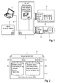
- FIG. 1 shows in an overall representation in the form of a block diagram of a test system 1 for performing a test of a control unit 2, in which a control unit 2 by means of a simulation architecture an environment is simulated, in particular such an environment, which also in the concrete use of the control unit 2 in a later device, such as a motor vehicle is present.
- the simulation architecture may already have multiple hardware components, e.g. include a computer of the test system 1, not shown here and be realized for example by a proprietary system of a particular manufacturer.
- a system of the patent applicant is shown, in which a plurality of hardware components 2, 3, 4 communicate with one another via a network 6 and are connected to the test system 1, on which the computer, not shown, is simulated a test environment.
- the hardware components 2,3,4 e.g. be integrated into the network 6 by intelligent nodes or routers, in particular if they do not themselves have suitable network interfaces.
- a control computer 5 connected to the test system can be provided via the same first network 6, for example in order to parameterize the test system or to charge and start the required software or a model or to communicate with the test system for other reasons.
- At least the simulation-individual components 2, 3, 4, if appropriate, also the computer of the test environment or the combined proprietary hardware of the Test environment 1 and also the control computer 5 include a server, which is shown here as MIS, as an abbreviation for micro-information server.
- This server is embodied in software either on the hardware component 2, 3, 4 or 1.5, directly itself or in a separate server hardware arranged thereon.
- the respective server MIS can communicate with a client on the computer of the test system 1 or a client on the control computer 5 via the same network 6 and thereby obtain access to configuration data which are required in the execution of the model with the respective hardware component. It can be done after transferring the configuration data to the control computer 5 or the computer of the test system 1, an adaptation of the model depending on the configuration data.
- control unit 2 does not have its own server, but is connected via a connecting element 2a with the test system 1, wherein the connecting element has a server MIS and thereby a new unit 2 'is formed with server MIS.
- FIG. 2 Visualizes a server hardware 7, which may be arranged separately to the hardware components on this or may be formed by a part of the hardware components.
- this server hardware 7 comprises a network interface 8 in order, for example, to communicate with the same network 6 via which the communication is also carried out in the simulation or with another separate network.
- An embodiment shown here provides that in the server hardware 7 two at least logically possibly. Physically separate memory areas 9a, 9b are provided in which public and non-public configuration data or additional data can be kept, to which one in the Server hardware 7 running server software 10 access granted. This access takes place via the network interface 8 by a client, for example the control computer 5, the test system computer or even a client 11, which is realized in another server hardware of another hardware component.
- a client for example the control computer 5, the test system computer or even a client 11, which is realized in another server hardware of another hardware component.
- the individual hardware components 7 via the network interface 8 and the individually existing server and client functions are networked with each other and exchange your data with each other.
- one of the computers mentioned can communicate only with a server 10 of a hardware component, but also gain access via this hardware component to the (configuration) data of other hardware components.
Landscapes
- Engineering & Computer Science (AREA)
- Physics & Mathematics (AREA)
- General Physics & Mathematics (AREA)
- Automation & Control Theory (AREA)
- Theoretical Computer Science (AREA)
- Geometry (AREA)
- Evolutionary Computation (AREA)
- General Engineering & Computer Science (AREA)
- Computer Hardware Design (AREA)
- Test And Diagnosis Of Digital Computers (AREA)
- Testing And Monitoring For Control Systems (AREA)
- Architecture (AREA)
- Software Systems (AREA)
Abstract
Description
- Die Erfindung betrifft ein Verfahren zur Durchführung einer Konfiguration eines Steuergeräte-Testsystems mit daran angeschlossenen Hardware-Komponenten, wobei mit dem Testsystem Steuergeräte in einer vom Testsystem mittels eines Modells simulierten Umgebung testbar sind und wobei das Testsystem zumindest einen Rechner, insbesondere einen das Modell ausführenden Rechner und Hardware-Komponenten umfasst, die mittels wenigstens eines Netzwerks miteinander verbunden sind.
- Testsysteme zur Durchführung von Steuergerätetests sind im Stand der Technik bekannt. Getestet werden können beispielsweise Steuergeräte für Kraftfahrzeuge ebenso wie für andere Vorrichtungen, beispielsweise Fertigungsautomaten, wie Roboter oder auch andere Beförderungsmittel, wie beispielsweise Flugzeuge. Alle diese Vorrichtungen haben im Wesentlichen gemeinsam, dass diese wenigstens ein zu testendes Steuergerät aufweisen, welches Umweltdaten oder Daten von mit der Umwelt interagierenden Sensoren erfasst und hierauf reagiert.
- Um die (einwandfreie) Funktion von Steuergeräten zu überprüfen, wird auf ein Verfahren zurückgegriffen, welches auch als "Hardware-in-the-loop" bezeichnet wird und welches im Wesentlichen besagt, dass ein konkret real existierendes elektronisches Steuergerät getestet wird, wofür dieses Steuergerät in ein Testsystem integriert wird, welches wenigstens einen Rechner umfasst, der eine Testumgebung simuliert, beispielsweise anhand eines darin gespeicherten und ausgeführten Modells sowie auch weiterhin Hardwarekomponenten umfasst, die miteinander zum Zweck der Kommunikation verbunden sind, was beispielsweise über wenigstens ein Netzwerk, insbesondere ein als Bus ausgebildetes Netzwerk erfolgen kann.
- Typische Hardwarekomponenten, zu denen auch das zu testende Steuergerät selbst gehört, können beispielsweise Kabelbäume sein, mechatronische Komponenten, Echtlasten sowie sonstige Elektroniken, die zur Durchführung eines individuellen Tests benötigt werden, z.B. A/D-Wandler, Schnittstellen etc.
- Insbesondere durch Echtlasten kann berücksichtigt werden, dass bei einem durchzuführenden Test gegebenenfalls bestimmte Umweltbedingungen, wie äußere Einflüsse auf ein Steuergerät nicht durch ein Modell in einer Simulation bereitgestellt werden, so dass in einem solchen Fall tatsächliche reale Lasten, zum Beispiel Aktoren, Sensoren oder sonstige Datengeber, insbesondere konkrete Hardwarekomponenten eines Systems, in welches ein Steuergerät bei seiner späteren Funktion eingebunden ist, an das Testsystem angeschlossen werden.
- Ein konkretes Beispiel aus dem Kraftfahrzeugbereich ist die Anbindung einer Drosselklappe an das Testsystem, da diese ein simulativ nur schwer bis gar nicht erfassbares Verhalten aufweist. Ebenso können andere Echtlasten, wie z.B. ein Lenksystem oder ein Gas-, Brems- oder Kupplungspedal angeschlossen werden, auch wenn diese grundsätzlich simulierbar sind.
- Ein konkreter Test kann beispielsweise vorsehen, dass die Eingänge eines Steuergerätes mit Sensordaten aus einem Modell stimuliert werden oder alternativ, sofern solche Sensordaten nicht aus einem Modell durch Simulation erhalten werden können, durch Daten aus den eingangs genannten realen Komponenten stimuliert werden.
- Die Reaktion eines zu testenden Steuergerätes auf solche Daten kann durch das Rücklesen von Ausgangsdaten des Steuergerätes in das Modell beziehungsweise den das Modell ausführenden Rechner erfolgen und somit überprüft, also getestet werden. Vorteilhaft ist es, dass ein solches Testsystem im Wesentlichen in Echtzeit dem zu testenden Steuergerät eine Umgebung simulieren kann, so dass das Steuergerät getestet werden kann, als wäre es tatsächlich in derjenigen Vorrichtung verbaut, in der es später zum Einsatz kommen soll. Um Echtzeitfähigkeit zu ermöglichen, können Simulationszyklen eine bevorzugte Dauer von weniger als 1 ms aufweisen.
- Eventuelle Fehler eines Steuergerätes können mittels eines solchen Testsystems frühzeitig erkannt, insbesondere durch wiederkehrende Simulationsabläufe reproduziert werden und die Beseitigung von aufgefundenen Fehlern, insbesondere durch Wiederholung der Testabläufe, die zum Fehler geführt haben, verifiziert werden.
- Für die einwandfreie Funktion eines Testsystems ist es wesentlich, dass auch die Konfiguration des Testsystems korrekt durchgeführt wurde. Eine solche Konfiguration, das heißt die Zusammenstellung der einzelnen Hardware-Komponenten des Testsystems und die Berücksichtigung solcher Hardware-Komponenten in einem auszuführenden Modell, wird im Wesentlichen von Menschenhand durchgeführt, so dass sich eine Fehleranfälligkeit des Testsystems, insbesondere das darin ausgeführten Modells, auch dadurch ergibt, dass bei der Konfiguration falsche Hardwarekomponenten zu einem programmierten Modell verwendet werden oder ein falsches Modell oder zumindest falsch konfiguriertes oder parametriertes Modell für die gegebenen Hardware-Komponenten zusammengestellt, bzw. programmiert wurde.
- Soll beispielsweise ein bestimmter Test, das heißt eine bestimmte Umweltbedingung oder Interaktion eines Steuergerätes mit der simulierten Umwelt, getestet werden, so kann ein Fehler schon dadurch erzeugt werden, dass ein Modell bei der Simulation verwendet wird, welches Daten erwartet, die von den Hardware-Komponenten nicht bereit gestellt werden oder welches diese Daten in einer für die betreffenden Hardwarekomponenten nicht geeigneten Weise verarbeitet.
- Soll beispielsweise mittels eines Testsystems eine in einem Steuergerät implementierte Drosselklappensteuerung eines 6-Zylinder-Motors überprüft werden, so kann dieser Test ersichtlich nicht korrekt durchgeführt werden, wenn eine Konfigurierung bzw. Parametrierung des verwendeten Modells für eine 4-Zylinder-Drosselklappe erfolgt.
- Die Fehleranfälligkeit eines von Hand konfigurierten Testsystems, insbesondere die Konfiguration oder Parametrierung des Modells kann beispielsweise reduziert werden, wenn eine Möglichkeit geschaffen wird, die technischen Anforderungen, die eine Hardware-Komponente an das Testsystem und hier insbesondere an das auszuführende Modell stellt, automatisiert dem Testsystem mitzuteilen.
- Die Aufgabe der Erfindung ist es, ein Verfahren zur Konfiguration eines Steuergeräte-Testsystems, und hier insbesondere das darin ausgeführen Modells, bereit zu stellen, das im Wesentlichen menschliche Einflüsse als Fehlerquelle ausschließt und die Konfiguration automatisiert, insbesondere zur Erzielung einer größeren Prozesssicherheit.
- Bevorzugt soll ein Verfahren bereitgestellt werden, das automatisch eine Konfiguration erstellt oder zumindest zu dieser beiträgt. So soll bevorzugt auch sichergestellt werden, dass bei einem Test auftretende Fehler auf eine Fehlfunktion im Steuergerät zurückzuführen sind, nicht jedoch auf einen Fehler im Testsystem, insbesondere bei der Konfiguration des Modells selbst.
- Als Modell wird hier beispielsweise eine Software verstanden, die durch den Rechner eines Testsystems ausgeführt wird und mit den einzelnen an das Testsystem angeschlossenen Hardwarekomponenten kommuniziert zum Zweck des Datenaustausches im Rahmen der Simulation einer Umweltbedingung oder - umgebung.
- Das im Stand der Technik verankerte Problem der fehlerhaften technischen Konfiguration des Modells eines Testsystems oder auch von dessen Hardware-Komponenten, kann erfindungsgemäß dadurch gelöst werden, dass zumindest ein Teil der Hardware-Komponenten einen eigenen Server umfasst, der durch Kommunikation Zugang gewährt zu der Hardware-Komponente zugeordneten, insbesondere in der Hardware-Komponente gespeicherten Konfigurationsdaten und das Modell und/oder die Hardware-Komponente in Abhängigkeit der zugänglich gemachten Konfigurationsdaten angepasst, insbesondere konfiguriert wird.
- Der wesentliche Kerngedanke des Verfahrens beruht demnach darauf, dass erfindungsgemäß zumindest ein Teil der an ein Testsystem angeschlossenen Hardwarekomponenten, bevorzugt alle Hardware-Komponenten selbst, die Konfigurationsdaten trägt bzw. mit sich führt, die in dem Testsystem, insbesondere ein dem Modell des Testsystems zur Durchführung von Test in Verbindung mit dieser Hardware-Komponente benötigt werden. Hierbei werden diese benötigten bzw. exakt zu der betreffenden Hardware-Komponente passenden Konfigurationsdaten mittels eines Servers zugänglich gemacht, der auf bzw. in dieser Hardware-Komponente abläuft.
- Dabei wird unter einem Server eine Software bzw. ein Programm verstanden, das mit einem anderen Programm - auch als Client bezeichneten Programm - kommuniziert, um diesem anderen Programm Zugang zu speziellen Daten oder Diensten zu verschaffen.
- Dabei kann es bevorzugt vorgesehen sein, dass zumindest alle solche Hardware-Komponenten mit einem Server versehen sind oder versehen werden, die als simulationsindividuell anzusehen sind, das heißt deren nicht korrekte individuelle Berücksichtigung im Modell des Testsystems sich auf das Simulationsergebnis beziehungsweise die Korrektheit des Testergebnisses unmittelbar auswirkt.
- So kann es demnach in einem Testsystem zur Durchführung von Tests bei Steuergeräten durchaus Hardwarekomponenten geben, die allgemein für jegliche Art von Simulation und Tests an Steuergeräten eingesetzt werden können, die demnach also nicht simulationsindividuell sind, so dass solche Hardwarekomponenten generell innerhalb eines Testsystems unabhängig von der durchzuführenden Simulation bzw. dem Modell korrekt funktionsfähig sind, somit also ein Modell keiner individuellen Anpassung bzw. Konfiguration bedarf.
- Bei solchen Hardwarekomponenten kann demnach keine Falschkonfiguration des Modells beziehungsweise kein fehlerhaftes Einbinden in ein Testsystem stattfinden, so dass es gegebenenfalls vorgesehen sein kann, solche Hardwarekomponenten ohne Server-Funktion in dem Testsystem zu verwenden.
- Bevorzugt werden zumindest Hardwarekomponenten mit Servern ausgestattet, die für eine jeweils durchzuführende Simulation eine spezielle Anpassung bzw. Konfiguration des Modells oder auch von sich selbst benötigen. Ein Beispiel bildet die bereits eingangs genannte 6-Zylinder-Drosselklappe, die eine als Echtlast zu bezeichnende Hardwarekomponente darstellt, und die in einem nur für eine 4-Zylinder-Drosselklappe programmierten Modell zu einer Fehlfunktion führen würde, die sodann aber auf einer fehlerhafte Modellprogrammierung zurückzuführen wäre, nicht jedoch auf ein fehlerhaftes Steuergerät.
- In diesem Beispiel kommt es somit darauf an, im Testsystem eine korrekte Paarung aus Steuergerät, Echtlast und dem Modell, welches die Daten aus diesen verarbeitet, zu erzielen.
- Erfindungsgemäß kann es vorgesehen sein, dass im Rahmen der Zugangsgewährung durch Kommunikation mit dem Server ein Auslesen von solchen Konfigurationsdaten aus der Hardwarekomponente erfolgt, die bei der Ausführung des Modells oder bei der Kommunikation der Hardwarekomponente während einer Simulation benötigt werden. Die Konfigurationsdaten können somit verwendet werden um z.B. das Modell des Testsystems anzupassen bzw. zu ändern, welches auf dem Rechner des Testsystems ausgeführt wird. Alternativ oder zusätzlich können die Konfigurationsdaten auch verwendet werden, um die betreffende Hardwarekomponente, die den Server umfasst, zu konfigurieren.
- Hierbei kann es erfindungsgemäß auch vorgesehen sein, dass das jeweilige Auslesen der Konfigurationsdaten aus den einzelnen Hardwarekomponenten, insbesondere den simulationsindividuellen Hardwarekomponenten mittels desjenigen Rechners des Testsystems erfolgt, welcher auch die eigentliche Simulation anhand des Modells, dass heißt eines im Wesentlichen auf dem Rechner vorhandenen durchzuführenden Simulationsalgorithmus durchführt.
- Alternativ besteht auch die Möglichkeit, die einzelnen Konfigurationsdaten von den jeweiligen Hardwarekomponenten mittels eines an das Testsystem angeschlossenen Steuerrechners zu lesen, beispielsweise eines solchen Steuerrechners, mittels welchem auch im übrigen eine softwareseitige Konfiguration des Testsystems erfolgt.
- Beispielsweise kann mittels eines solchen Steuerrechners auf den Rechner des Testsystems das Modell, das heißt die eine bestimmte Umweltbedingung simulierende Software übertragen werden und/oder mit zur Simulation benötigten Parametern versehen werden. Ebenso besteht die Möglichkeit mittels eines solchen Steuer-PCs Ergebnisse aus dem Testsystem auszulesen und gegebenenfalls zu visualisieren, insbesondere zur Überprüfung der Testsysteme durch Benutzer.
- Unabhängig davon, welcher dieser Rechner Verwendung findet kann das Auslesen bedingen, dass ein Client-Prozess ausgeführt auf dem betreffenden Rechner, der mit dem Server der Hardware-Komponente kommuniziert, um über diesen Server den Zugang zu den Konfigurationsdaten zu erhalten.
- Bei einem Auslesen mittels eines an das Testsystem angeschlossenen Steuer-Rechners kann sodann dieser Steuerrechner anhand aller von mehreren Hardware-Komponenten erhaltener Konfigurationsdaten die Konfiguration des auf dem Rechner des Testsystems laufenden Modells vornehmen bzw. auch die Konfiguration der einzelnen Hardware-Komponenten durchführen.
- Typische Konfigurationsdaten können z.B. gebildet werden durch eine durch den Rechner des Testsystems ausführbare Modellkomponente, insbesondere Simulink-Komponente. Konfigurationsdaten können somit selbst auch eine Software darstellen, die zum Ablauf auf dem Testsystem bei der Verwendung dieser speziellen Hardware-Komponente, von der die Konfigurationsdaten stammen, benötigt wird.
- Alternativ oder zusätzlich können Konfigurationsdaten auch beispielsweise Parameter oder Kennlinien eines Modells oder einer Modellkomponente umfassen oder auch eine die Hardware-Komponente beschreibende Information.
- Neben der erfindungswesentlichen Möglichkeit Konfigurationsdaten zum Zweck der Anpassung des Testsystems, insbesondere des Modells oder der Hardware-Komponenten durch die Hardware-Komponenten selbst zu liefern, kann eine Weiterbildung auch zusätzlich vorsehen, dass ein Server einer Hardware-Komponente auch Zugang gewährt zu einer die Hardware-Komponente identifizierenden Information, insbesondere zu einer Seriennummer, insbesondere zur Durchführung einer Inventarisierung der Hardware-Komponenten des Testsystems. Eine solche Inventarisierung, d.h. z.B. eine gespeicherte, identifizierende Komponenteninformationen wiedergebende Liste kann beispielsweise mittels des genannten Steuerrechners visualisiert werden.
- Eine erste mögliche vorteilhafte weitere Ausführung des erfindungsgemäßen Verfahrens kann es vorsehen, dass der Server einer Hardware-Komponente implementiert ist durch eine Software, die durch einen für die Funktion der Hardware-Komponente während eines Tests verwendeten Prozessor ausgeführt wird. Der Prozessor arbeitet somit sowohl während einer Simulation zum Zweck der Simulation, insbesondere derart, dass ohne diesen Prozessor die Simulation nicht möglich ist, als auch für die hier erfindungsgemäß durchgeführte Konfiguration. Dies ist beispielsweise der Fall bei einem Prozessor, auf welchem während der Durchführung eines Tests Prozessschritte durchgeführt werden.
- Eine andere Ausführung, die auch mit der vorherigen kombinierbar ist, kann vorsehen, dass der Server implementiert ist durch eine Software, die auf einem für die Funktion der Hardware-Komponente während eines Tests nicht benötigten Server-Hardware, insbesondere die einen Prozessor umfasst, ausgeführt wird, welche zum Zweck der Bereitstellung des Servers an der Hardware-Komponente angeordnet wird.
- Eine solche Server-Hardware kann in einer möglichen Ausführungsform keine andere Funktion aufweisen, als das Bereitstellen des Servers und ansonsten zumindest für die Durchführung eines Tests im Rahmen einer Simulation keine weitere Funktion haben, also am Test selbst nicht teilnehmen.
- Bei dieser Ausführung erschließt es sich als vorteilhaft, dass Hardwarekomponenten, die ggfs. keinen Prozessor aufweisen, für den Zweck des erfindungsgemäßen Verfahrens extra ausgerüstet werden können, zum Beispiel durch Anbringung einer zusätzlichen Server-Hardware an der Hardwarekomponente, um sodann die Konfigurationsdaten über den so realisierten Server auszulesen und im Rahmen der Anpassung des Testsystems zu verwenden.
- Eine weitere Ausführung des erfindungsgemäßen Verfahrens kann es hier auch vorsehen, dass bei Verwendung einer Hardwarekomponente, die entweder keinen Prozessor aufweist oder nicht nachträglich mit einer Server-Hardware ausgestattet werden kann, eine den Server dieser Hardwarekomponente ausführende Server-Hardware integriert wird in einem zur Verbindung dieser Hardwarekomponente mit dem Testsystem vorgesehenen Verbindungselement, insbesondere in einem Anschlußstecker eines solchen Verbindungselementes, wie z.B. eines Kabelbaumes, insbesondere wobei eine Aktivierung der Funktion des Servers erst durch eine Verbindung zwischen dieser Hardware-Komponente und dem Verbindungselement erfolgt. Bei einer solchen Hardwarekomponente kann es sich z.B. um ein Steuergerät handeln.
- Beispielsweise können die betreffende Hardwarekomponente und das Verbindungselement zu einer neuen Einheit verbunden werden, insbesondere zu einer solchen Einheit, die nicht ohne Zerstörung trennbar ist.
- Dies kann beispielsweise durch Verschrauben, Versiegeln oder Verplomben der Verbindung erfolgen.
- Bei der Durchführung des erfindungsgemäßen Verfahrens kann es weiterhin vorgesehen sein, dass die Konfigurationsdaten über dasselbe Netzwerk zwischen Server und dem beteiligten Rechner kommuniziert werden, mittels dem die Hardwarekomponente während der Simulation mit dem das Modell ausführenden Rechner kommuniziert.
- Es kann auch vorgesehen sein, dass ein Teil von Hardwarekomponenten des Testsystems mittels eines ersten Netzwerkes, beispielsweise mit einem ersten Bus an den Rechner des Testsystems angeschlossen ist und ein (anderer) Teil von Hardwarekomponenten des Testsystems, wie beispielsweise ein zu testendes Steuergerät und/oder Echtlasten mittels eines zweiten Netzwerkes, beispielsweise mit einem zweiten Bus an den Rechner des Testsystems angeschlossen ist, wobei die beiden Netzwerke, insbesondere die verwendeten Busse mittels eines Gateways verbunden sind, so dass sich hierdurch die Möglichkeit erschließt, Signale oder Daten auf einem der beiden Netzwerke auf das jeweils andere Netzwerk beziehungsweise den anderen Bus zu übertragen, insbesondere wobei ein solches Gateway beispielsweise eine Protokolltransformation vornehmen kann, sofern die beiden Netzwerke beziehungsweise Busse mit einem unterschiedlichen Kommunikationsprotokoll arbeiten.
- Beispielsweise kann es hier vorgesehen sein, dass als erstes Netzwerk ein solches Netzwerk benutzt wird, welches proprietär von einem Hersteller zumindest des Rechners des Testsystems gegebenenfalls auch für das Testsystem vorgesehener, zwingender, insbesondere nicht simulationsindividueller Komponenten verwendet wird, wohingegen als zweites Netzwerk ein gegebenenfalls standardisiertes Netzwerk verwendet werden kann, um über ein solches Netzwerk oder einen standardisierten Bus weitere, insbesondere externe Komponenten, wie die eingangs genannten Steuergeräte oder externe (Echt-) Lasten, an den Rechner des Testsystemes anzuschließen.
- Ein Beispiel für ein erstes Netzwerk kann das Netzwerk beziehungsweise der Bus IOCNET der Anmelderin dieser Erfindung eingesetzt werden, wobei als zweites Netzwerk der zum Beispiel in der Automobilindustrie etablierte CAN-Bus Verwendung finden kann. Es ist darauf hinzuweisen, dass die hier beschriebene Erfindung nicht auf die hier konkret benannten Netzwerke beziehungsweise Busse beschränkt ist, sondern selbstverständlich auch andere Netzwerke beziehungsweise Busse Verwendung finden können.
- Durch die beschriebene Verwendung eines Gateways zur Verbindung der wenigstens zwei Netzwerke kann so sichergestellt werden, dass auch Konfigurationsdaten von an das zweite Netzwerk angeschlossenen Hardwarekomponenten unmittelbar über das zweite Netzwerk ausgelesen werden von einer jeweiligen Hardwarekomponente und beispielsweise über das Gateway, insbesondere ein erstes Gateway auf das erste Netzwerk übertragen werden, insbesondere in welchem der Rechner des Testsystems angeordnet ist, so dass die Konfigurationsdaten zumindest diesem Rechner zum Zwecke der Anpassung des Testsystems zur Verfügung steht, beziehungsweise über dieses Netzwerk auch an einen an das Testsystem angeschlossenen Steuerrechner übermittelt werden können zu demselben Zweck. Dies setzt voraus, dass ein Prozessor bzw. eine Server-Hardware, sei die originär vorhanden oder nachgerüstet, an wenigstens eines der wenigstens zwei genannten Netzwerke (Busse) angeschlossen ist.
- Ist hingegen ein Server einer Hardwarekomponente, die im Testsystem eingebunden ist, weder über das eingangs genannte erste Netzwerk noch über das eingangs genannte zweite Netzwerk ansprechbar , was beispielsweise der Fall sein kann, wenn es sich um solche Hardwarekomponenten handelt, an denen zum Zweck der Bereitstellung eines Servers eine Server-Hardware ohne Bedeutung für die Funktion der Hardwarekomponente während eines Tests angeordnet ist, so kann es hier auch vorgesehen sein, die jeweiligem Konfigurationsdaten über ein Netzwerk zwischen Server und beteiligtem Rechner zu kommunizieren, welches zu demjenigen Netzwerk getrennt ist, mittels dem die Hardwarekomponente während der Simulation mit dem das Modell ausführenden Rechner kommuniziert. Zumindest der beteiligte Rechner ist sodann in wenigstens zwei getrennte Netzwerke eingebunden, eines für die Server-Kommunikation und eines für die Kommunikation bei einer Simulation.
- Ein solches getrenntes Netzwerk für die Server-Kommunikation kann in einfachem Fall ein Ethernet sein.
- Vorteilhaft ist die Ausführung mittels eines solchen getrennten Netzwerkes, da das Durchführen der erfindungsgemäßen Kommunikation zwischen Server und Rechner selbst dann eine Simulation, das heißt einen Test eines Steuergerätes nicht stört, sofern eine Übertragung von Konfigurationsdaten während der Laufzeit eines Tests vorgenommen wird.
- Echtzeitanforderungen an das Testsystem können somit problemlos während der Durchführung eines Tests fortwährend aufrechterhalten werden, ohne eine Beeinflussung durch die erfindungsgemäße Serverkommunikation befürchten zu müssen.
- Erfindungsgemäß kann es auch vorgesehen sein, dass ein Server Zugang gewährt zu zumindest einem Speicherplatz mit öffentlichen Daten und/oder zu zumindest einem Speicherplatz mit nicht-öffentlichen Daten, insbesondere nachdem der Server eine Authentifizierung eines anfragenden Rechners vorgenommen hat.
- Ein Speicherplatz kann unabhängig von einer evtl. Zugriffsbeschränkung z.B. durch einen Flash-Speicher ausgebildet sein, der auf der Hardwarekomponente bereits für die ordnungsgemäße Funktion während eines Tests vorgesehen ist oder auch der auf einer separaten Server-Hardware angeordnet ist.
- Eine bevorzugte Weiterbildung kann auch vorsehen, dass in der separaten Serverhardware mehrerer Hardware-Komponenten oder direkt in mehreren Hardwarekomponenten des Testsystems jeweils ein Client, insbesondere ein als Software ausgebildeter Client implementiert ist, wobei mittels des jeweiligen Client mehrere Server verschiedener Hardware-Komponenten miteinander vernetzt werden, die Konfigurationsdaten untereinander kommunizieren, insbesondere wobei ein beteiligter Rechner durch Kommunikation mit nur einem der vernetzten Server Zugang erhält zu den Konfigurationsdaten der mit diesem Server vernetzten anderen Server.
- Weiterhin kann ein Server eine Web-Server-Funktionalität umfassen, mittels der, insbesondere unter Verwendung des Steuer-Rechners, Änderungen an den durch den Server zugänglich gemachten Daten vorgenommen werden können.
- Ausführungsbeispiele der Erfindung werden im Nachfolgenden beschrieben.
- Die
Figur 1 zeigt in einer insgesamten Darstellung in der Form eines Blockdiagramms ein Testsystem 1 zur Durchführung eines Tests eines Steuergerätes 2, bei welchem einem Steuergerät 2 mittels einer Simulationsarchitektur eine Umgebung simuliert wird, insbesondere eine solche Umgebung, die auch bei dem konkreten Einsatz des Steuergerätes 2 in einer späteren Vorrichtung, wie beispielsweise einem Kraftfahrzeug vorliegt. - Die Simulationsarchitektur kann bereits mehrere Hardwarekomponenten, z.B. einen hier nicht gezeigten Rechner des Testsystems 1 umfassen und zum Beispiel durch ein proprietäres System eines bestimmten Herstellers realisiert sein. Vorliegend wird ein System der Patentanmelderin dargestellt, bei welchem über ein Netzwerk 6 mehrere Hardwarekomponenten 2,3,4 miteinander kommunizieren und an das Testsystem 1 angeschlossen sind, auf dem der nicht gezeigte Rechner eine Testumgebung simuliert wird.
- Hier können die Hardwarekomponenten 2,3,4 z.B. durch intelligente Knoten oder Router in das Netzwerk 6 eingebunden sein, insbesondere sofern sie nicht selbst geeignete Netzwerkschnittstellen aufweisen.
- Es kann weiterhin über das gleiche erste Netzwerk 6 auch ein an das Testsystem angeschlossener Steuerrechner 5 vorgesehen ist, beispielsweise um das Testsystem zu parametrisieren beziehungsweise die benötigte Software oder ein Modell aufzuladen und zu starten oder aus sonstigen Gründen mit dem Testsystem zu kommunizieren.
- Für das erfindungsgemäße Verfahren ist es hier vorgesehen, dass zumindest die simulationsindividuellen Komponenten 2,3,4 ggfs. auch der Rechner der Testumgebung bzw. die zusammengefasste proprietäre Hardware der Testumgebung 1 und auch der Steuerrechner 5 einen Server umfassen, der hier als MIS dargestellt ist, als Abkürzung für Micro-Information-Server.
- Dieser Server ist in Software ausgebildet entweder auf der Hardware-Komponente 2,3,4 bzw. auch 1,5, unmittelbar selbst oder in einer separaten daran angeordneten Server-Hardware. Der jeweilige Server MIS kann über dasselbe Netzwerk 6 mit einem Client auf den Rechner des Testsystems 1 oder einem Client auf dem Steuerrechner 5 kommunizieren und hierdurch Zugang erhalten zu Konfigurationsdaten, die bei der Ausführung des Modell mit der jeweiligen Hardwarekomponente benötigt werden. Es kann so nach einem Übertragen der Konfigurationsdaten zum Steuerrechner 5 oder den Rechner des Testsystem 1 eine Anpassung des Modells erfolgen in Abhängigkeit der Konfigurationsdaten.
- Bzgl. des Steuergerätes 2 ist dargestellt, dass dieses keinen eigenen Server aufweist, jedoch über ein Verbindungselement 2a mit dem Testsystem 1 verbunden ist, wobei das Verbindungelement einen Server MIS aufweist und hierdurch eine neue Einheit 2' mit Server MIS gebildet wird.
- Die
Figur 2 visualisiert eine Serverhardware 7, die separat zur Hardwarekomponenten an dieser angeordnet sein kann oder auch durch einen Teil der Hardwarekomponenten ausgebildet sein kann. Hier wird deutlich, dass diese Serverhardware 7 eine Netzwerkschnittstelle 8 umfasst, um z.B. mit demselben Netzwerk 6 zu kommunizieren, über welches auch die Kommunikation bei der Simulation abgewickelt wird oder mit einem anderen separaten Netzwerk. - Eine hier gezeigte Ausführung sieht vor, dass in der Server-Hardware 7 zwei zumindest logisch ggfs. auch physikalisch getrennte Speicherbereiche 9a, 9b vorgesehen sind, in denen öffentliche und nicht-öffentliche Konfigurationsdaten oder auch zusätzliche Daten vorgehalten werden können, zu denen eine in der Serverhardware 7 ablaufende Serversoftware 10 Zugang gewährt. Dieser Zugang erfolgt über die Netzwerkschnittstelle 8 durch einen Client, z.B. des Steuerrechners 5, des Testsystem-Rechners oder auch eines Clients 11, der in einer anderen Serverhardware einer anderen Hardware-Komponente realisiert ist. So können die einzelnen Hardware-Komponenten 7 über die Netzwerkschnittstelle 8 und die einzeln jeweils vorhandene Server- und Client-Funktion miteinander vernetzt werden und Ihre Daten auch untereinander austauschen. Z.B. kann einer der genannten Rechner nur mit einem Server 10 einer Hardware-Komponente kommunizieren, über diese Hardware-Komponente jedoch auch Zugang erhalten zu den (Konfigurations-) Daten anderer Hardware-Komponenten.
Claims (10)
- Verfahren zur Durchführung einer Konfiguration eines Steuergeräte-Testsystems (1) mit daran angeschlossenen Hardware-Komponenten (2,3,4), wobei mit dem Testsystem (1) Steuergeräte (2) in einer vom Testsystem (1) mittels eines Modells simulierten Umgebung testbar sind und wobei das Testsystem (1) zumindest einen Rechner, insbesondere das Modell ausführenden Rechner und Hardware-Komponenten (2,3,4) umfasst, die mittels wenigstens eines Netzwerks (6) miteinander verbunden sind, dadurch gekennzeichnet, dass zumindest ein Teil der Hardware-Komponenten (2,3,4) einen eigenen Server (MIS) umfasst, der durch Kommunikation Zugang gewährt zu der Hardware-Komponente (2,3,4) zugeordneten, insbesondere in der Hardware-Komponente (2,3,4) gespeicherten Konfigurationsdaten und das Modell und/oder die Hardware-Komponente (2,3,4) in Abhängigkeit der zugänglich gemachten Konfigurationsdaten angepasst, insbesondere konfiguriert wird.
- Verfahren nach Anspruch 1, dadurch gekennzeichnet, dass ein Auslesen der Konfigurationsdaten mittels des Rechners des Testsystems (1) oder mittels eines an das Testsystem (1) angeschlossenen Steuer-Rechners (5) erfolgt, insbesondere wobei bei einem Auslesen mittels eines an das Testsystem angeschlossenen Steuer-Rechners (5) dieser Steuerrechner (5) anhand aller von mehreren Hardware-Komponenten (2,3,4) erhaltener Konfigurationsdaten die Konfiguration des auf dem Rechner des Testsystems (1) laufenden Modells und/oder der Hardware-Komponenten (2,3,4) vornimmt.
- Verfahren nach einem der vorherigen Ansprüche, dadurch gekennzeichnet, dass der Server (MIS) einer Hardware-Komponente implementiert ist durcha. eine Software (10), die durch einen für die Funktion der Hardware-Komponente (2,3,4) während eines Tests verwendete Prozessor ausgeführt wird, oderb. eine Software (10), die auf einem für die Funktion der Hardware-Komponente (2,3,4) während eines Tests nicht benötigten Server-Hardware (7), insbesondere die einen Prozessor umfasst, ausgeführt wird, welche zum Zweck der Bereitstellung des Servers (MIS) an der Hardware-Komponente (2,3,4) angeordnet wird.
- Verfahren nach Anspruch 3, dadurch gekennzeichnet, dass die Konfigurationsdaten über dasselbe Netzwerk (6) zwischen Server (MIS) und dem beteiligten Rechner (5) kommuniziert werden, mittels dem die Hardwarekomponente (2,3,4) während der Simulation mit dem das Modell ausführenden Rechner kommuniziert.
- Verfahren nach Anspruch 3, dadurch gekennzeichnet, dass die Konfigurationsdaten über ein Netzwerk zwischen Server und dem beteiligten Rechner kommuniziert werden, welches von demjenigen Netzwerk (6) getrennt ist, mittels dem die Hardwarekomponente (2,3,4) während der Simulation mit dem das Modell ausführenden Rechner kommuniziert.
- Verfahren nach einem der vorherigen Ansprüche, dadurch gekennzeichnet, dass eine den Server (MIS) einer zu testenden Hardwarekomponente (2,3,4) ausführende Server-Hardware (7) integriert wird in ein zur Verbindung einer Hardwarekomponente (2) mit dem Testsystem (1) vorgesehenen Verbindungselement (2a), insbesondere in einen Anschlußstecker eines Verbindungselementes (2a), insbesondere Kabelbaumes.
- Verfahren nach einem der vorherigen Ansprüche, dadurch gekennzeichnet, dass ein Server (MIS) Zugang gewährta. zu zumindest einem Speicherplatz (9a) mit öffentlichen Daten und/oderb. zu zumindest einem Speicherplatz (9b) mit nicht-öffentlichen Daten, nachdem der Server (MIS) eine Authentifizierung eines anfragenden Rechners (5) vorgenommen hat.
- Verfahren nach einem der vorherigen Ansprüche, dadurch gekennzeichnet, dass in der separaten Serverhardware (7) mehrerer Hardware-Komponenten (2,3,4) oder direkt in mehreren Hardwarekomponenten (2,3,4) des Testsystems (1) jeweils ein Client (11), insbesondere ein als Software ausgebildeter Client (11) implementiert ist, wobei mittels des jeweiligen Clients (11) mehrere Server (MIS) verschiedener Hardware-Komponenten (2,3,4) miteinander vernetzt werden, die Konfigurationsdaten untereinander kommunizieren, insbesondere wobei ein beteiligter Rechner (5) durch Kommunikation mit einem der vernetzten Server (MIS) Zugang erhält zu den Konfigurationsdaten der mit diesem Server (MIS) vernetzten anderen Server (MIS).
- Verfahren nach einem der vorherigen Ansprüche, dadurch gekennzeichnet, dass ein Server (MIS) eine Web-Server-Funktionalität umfasst, mittels der, insbesondere unter Verwendung des Steuer-Rechners (5), Änderungen an den durch den Server (MIS) zugänglich gemachten Daten vorgenommen werden können.
- Verfahren nach einem der vorherigen Ansprüche, dadurch gekennzeichnet, dass Konfigurationsdaten gebildet werden durch zumindest eine Art der folgenden Daten:a. Eine durch den Rechner des Testsystems (1) ausführbare Modellkomponente, insbesondere Simulink-Komponenteb. Parameter oder Kennlinien eines Modellsc. Eine die Hardware-Komponente beschreibende InformationVerfahren nach einem der vorherigen Ansprüche, dadurch gekennzeichnet, dass ein Server (MIS) einer Hardware-Komponente (2,3,4) Zugang gewährt zu einer die Hardware-Komponente (2,3,4) identifizierenden Information, insbesondere zu einer Seriennummer, insbesondere zur Durchführung einer Inventarisierung der Hardware-Komponenten (2,3,4) des Testsystems (1).
Priority Applications (4)
| Application Number | Priority Date | Filing Date | Title |
|---|---|---|---|
| EP13156323.1A EP2770389B1 (de) | 2013-02-21 | 2013-02-22 | Verfahren zur Durchführung einer Konfiguration eines Steuergeräte-Testsystems |
| CN201410048369.XA CN104007752A (zh) | 2013-02-22 | 2014-02-12 | 用于对控制仪-测试系统实施配置的方法和测试系统 |
| JP2014032725A JP5972303B2 (ja) | 2013-02-22 | 2014-02-24 | 制御装置テストシステムのコンフィギュレーション設定の実行方法 |
| US14/187,847 US10025883B2 (en) | 2013-02-22 | 2014-02-24 | Method for generating a configuration for a control unit test system |
Applications Claiming Priority (2)
| Application Number | Priority Date | Filing Date | Title |
|---|---|---|---|
| EP13000867.5A EP2770434B1 (de) | 2013-02-21 | 2013-02-21 | Verfahren zur Durchführung einer Inventarisierung der an ein Steuergeräte-Testsystem angeschlossenen Hardware-Komponenten |
| EP13156323.1A EP2770389B1 (de) | 2013-02-21 | 2013-02-22 | Verfahren zur Durchführung einer Konfiguration eines Steuergeräte-Testsystems |
Publications (3)
| Publication Number | Publication Date |
|---|---|
| EP2770389A2 true EP2770389A2 (de) | 2014-08-27 |
| EP2770389A3 EP2770389A3 (de) | 2017-01-25 |
| EP2770389B1 EP2770389B1 (de) | 2019-05-08 |
Family
ID=47877776
Family Applications (1)
| Application Number | Title | Priority Date | Filing Date |
|---|---|---|---|
| EP13156323.1A Active EP2770389B1 (de) | 2013-02-21 | 2013-02-22 | Verfahren zur Durchführung einer Konfiguration eines Steuergeräte-Testsystems |
Country Status (4)
| Country | Link |
|---|---|
| US (1) | US10025883B2 (de) |
| EP (1) | EP2770389B1 (de) |
| JP (1) | JP5972303B2 (de) |
| CN (1) | CN104007752A (de) |
Cited By (2)
| Publication number | Priority date | Publication date | Assignee | Title |
|---|---|---|---|---|
| CN106708025A (zh) * | 2017-02-22 | 2017-05-24 | 奇瑞汽车股份有限公司 | 一种识别电子控制器故障的方法及诊断工具 |
| DE102016107797A1 (de) * | 2016-04-27 | 2017-11-02 | Dspace Digital Signal Processing And Control Engineering Gmbh | Verfahren zur Konfiguration eines zum Testen eines elektronischen Steuergeräts eingerichteten Testgeräts |
Families Citing this family (16)
| Publication number | Priority date | Publication date | Assignee | Title |
|---|---|---|---|---|
| US10171184B2 (en) | 2014-12-05 | 2019-01-01 | W2Bi, Inc. | Methodology of using the various capabilities of the smart box to perform testing of other functionality of the smart device |
| EP3115859B1 (de) | 2015-07-08 | 2021-08-25 | Siemens Aktiengesellschaft | Verfahren und konfigurationssystem zum konfigurieren von hardware-baugruppen in einem automatisierungssystem |
| CN106302010B (zh) * | 2016-08-11 | 2019-06-04 | 北京经纬恒润科技有限公司 | 一种CANopen网络通信仿真测试方法及相关设备 |
| US10701571B2 (en) | 2016-08-12 | 2020-06-30 | W2Bi, Inc. | Automated validation and calibration portable test systems and methods |
| US10158552B2 (en) | 2016-08-12 | 2018-12-18 | W2Bi, Inc. | Device profile-driven automation for cell-based test systems |
| US10251079B2 (en) | 2016-08-12 | 2019-04-02 | W2Bi, Inc. | Cloud-based services for management of cell-based test systems |
| US10548033B2 (en) | 2016-08-12 | 2020-01-28 | W2Bi, Inc. | Local portable test systems and methods |
| US10681570B2 (en) * | 2016-08-12 | 2020-06-09 | W2Bi, Inc. | Automated configurable portable test systems and methods |
| CN107957719B (zh) * | 2016-10-18 | 2020-10-23 | 珠海格力智能装备有限公司 | 机器人及其异常监控方法和装置 |
| CN106774261A (zh) * | 2016-12-23 | 2017-05-31 | 广东嘉腾机器人自动化有限公司 | 一种agv数据配置系统及其数据的烧录和导入方法 |
| DE102018212560A1 (de) * | 2017-08-08 | 2019-02-14 | Robert Bosch Gmbh | Rechnergestütztes System zum Testen einer servergestützten Fahrzeugfunktion |
| CN108490915A (zh) * | 2018-03-28 | 2018-09-04 | 合肥凯利科技投资有限公司 | 一种基于gprs网络的电机控制器远程监控系统 |
| CN112087360A (zh) * | 2019-06-13 | 2020-12-15 | 罗德施瓦兹两合股份有限公司 | 远程访问和控制系统及相应方法 |
| CN110304268B (zh) * | 2019-06-20 | 2022-03-15 | 成都飞机工业(集团)有限责任公司 | 一种飞机系统的总装测试方法 |
| CN110941520B (zh) * | 2019-12-28 | 2023-09-08 | 卡斯柯信号有限公司 | 基于二取二安全控制单元的硬件功能测试系统及方法 |
| DE102021118943A1 (de) * | 2021-07-22 | 2023-01-26 | Dspace Gmbh | Schleifen-Modus für simulierte Steuergeräte |
Family Cites Families (36)
| Publication number | Priority date | Publication date | Assignee | Title |
|---|---|---|---|---|
| JPS62100957A (ja) * | 1985-10-25 | 1987-05-11 | 株式会社 富山パ−ツ | コンピユ−タ用コネクタ− |
| JPH1054868A (ja) * | 1996-08-09 | 1998-02-24 | Advantest Corp | 集積回路テストシステムのソフトウエア設定方法 |
| JP3999290B2 (ja) * | 1996-08-27 | 2007-10-31 | 株式会社アドバンテスト | 半導体試験装置 |
| JPH1126095A (ja) * | 1997-06-30 | 1999-01-29 | Amp Japan Ltd | 電子制御スイッチ付コネクタ装置 |
| FR2811183B1 (fr) * | 2000-06-30 | 2006-09-01 | Schneider Automation | Bloc fonction web dans un equipement d'automatisme |
| JP2002113675A (ja) * | 2000-10-11 | 2002-04-16 | Sony Corp | ロボット制御システム並びにロボット制御用ソフトウェアの導入方法 |
| EP1235168A2 (de) | 2000-10-23 | 2002-08-28 | Elsa AG | Verfahren zum Betrieb eines Peripherie-Gerätes an einem Bus eines Computers sowie Peripheriegerät |
| WO2002056185A1 (fr) * | 2001-01-12 | 2002-07-18 | Fujitsu Limited | Procede de gestion de donnees de configuration de materiel informatique |
| JP4349199B2 (ja) | 2003-05-21 | 2009-10-21 | 株式会社日立製作所 | 時空間通信システム |
| JP2004361292A (ja) | 2003-06-05 | 2004-12-24 | Toyota Motor Corp | 電子制御ユニットの自動検査装置 |
| JP2005048764A (ja) | 2003-07-29 | 2005-02-24 | Sumitomo Heavy Ind Ltd | 真空ポンプ制御システム |
| US7293117B2 (en) | 2004-06-10 | 2007-11-06 | Microsoft Corporation | Self-installing peripheral device with memory wherein in response to user request for additional storage peripheral device being configured to remove installation software stored on memory |
| JP4379336B2 (ja) * | 2005-01-07 | 2009-12-09 | トヨタ自動車株式会社 | 制御システムの評価装置、その評価装置に用いられる検証装置、制御システムの評価方法、及びそれらに用いるコンピュータプログラム |
| JP2006350549A (ja) | 2005-06-14 | 2006-12-28 | Hitachi Ltd | 統合シミュレーションシステム |
| JP2007058433A (ja) | 2005-08-23 | 2007-03-08 | Fuji Electric Fa Components & Systems Co Ltd | プログラマブルコントローラのプログラミング装置および機器構成の診断方法 |
| US8707017B2 (en) * | 2005-12-29 | 2014-04-22 | Intel Corporation | Method and system for managing core configuration information |
| DE102006000943A1 (de) * | 2006-01-07 | 2007-07-26 | Deutsche Telekom Ag | HiL-System und -Verfahren zum Testen von Steuergeräten eines Steuersystems |
| CA2636010A1 (en) * | 2006-01-17 | 2007-07-17 | Baker Hughes Inc | SYSTEM AND METHOD FOR REMOTE DATA ACQUISITION AND DISTRIBUTION |
| EP2194432B1 (de) | 2006-09-11 | 2011-11-09 | dSPACE digital signal processing and control engineering GmbH | Scheduling-Verfahren |
| DE102006044141A1 (de) * | 2006-09-15 | 2008-04-03 | Dspace Digital Signal Processing And Control Engineering Gmbh | Einrichtung und Verfahren zur Konfiguration eines Steuerungssystems |
| US8065397B2 (en) | 2006-12-26 | 2011-11-22 | Axeda Acquisition Corporation | Managing configurations of distributed devices |
| DE102007029285A1 (de) | 2007-06-22 | 2008-12-24 | Dspace Digital Signal Processing And Control Engineering Gmbh | Testvorrichtung zum Testen wenigstens eines elektronischen Steuerungssystems sowie Verfahren zum Betreiben einer Testvorrichtung |
| US8433953B1 (en) * | 2007-08-13 | 2013-04-30 | The Mathworks, Inc. | Automatic configuration of a test environment |
| JP2009134699A (ja) | 2007-10-31 | 2009-06-18 | Daikin Ind Ltd | データ収集装置およびデータ管理システム |
| JP2009294745A (ja) * | 2008-06-03 | 2009-12-17 | Keihin Corp | モデル検証プログラム及びモデル検証装置 |
| AT10236U3 (de) | 2008-07-10 | 2009-09-15 | Avl List Gmbh | Messanordnung und verfahren zur erfassung von messdaten |
| AT10759U3 (de) * | 2009-04-23 | 2010-07-15 | Avl List Gmbh | Verfahren und vorrichtung zur verifizierung eines automatisierungssystems |
| US8239824B2 (en) * | 2009-05-18 | 2012-08-07 | National Instruments Corporation | Developing a graphical data flow program with multiple models of computation in a web browser |
| EP2343611A1 (de) * | 2010-01-07 | 2011-07-13 | dspace digital signal processing and control engineering GmbH | Verfahren zur rechnergestützten Erzeugung eines ausführbaren Steuerungsprogramms und diesbezügliche Konfigurationseinrichtung |
| JP2011252805A (ja) * | 2010-06-02 | 2011-12-15 | Denso Corp | 車両評価システム |
| CN102262695A (zh) | 2010-11-08 | 2011-11-30 | 帝斯贝思数字信号处理和控制工程有限公司 | 实现和/或配置输入/输出模型的工具 |
| DE102010043661A1 (de) * | 2010-11-09 | 2012-05-10 | Dspace Digital Signal Processing And Control Engineering Gmbh | Vorrichtung zum Testen und HIL-Simulator |
| US9110496B1 (en) * | 2011-06-07 | 2015-08-18 | Interactive TKO, Inc. | Dynamic provisioning of a virtual test environment |
| CN102520711B (zh) * | 2011-11-28 | 2014-07-02 | 联合汽车电子有限公司 | Amt控制器的硬件在环仿真系统及其自动测试方法 |
| DE102011087382A1 (de) | 2011-11-30 | 2013-06-06 | Robert Bosch Gmbh | Verfahren zum Vorkonfigurieren eines Gerät und Verfahren zur Inbetriebnahme des Geräts |
| CN102880171B (zh) | 2012-10-15 | 2015-08-26 | 保定长安客车制造有限公司 | 一种电动汽车整车控制器的硬件在环实验系统 |
-
2013
- 2013-02-22 EP EP13156323.1A patent/EP2770389B1/de active Active
-
2014
- 2014-02-12 CN CN201410048369.XA patent/CN104007752A/zh active Pending
- 2014-02-24 JP JP2014032725A patent/JP5972303B2/ja active Active
- 2014-02-24 US US14/187,847 patent/US10025883B2/en active Active
Non-Patent Citations (1)
| Title |
|---|
| None |
Cited By (3)
| Publication number | Priority date | Publication date | Assignee | Title |
|---|---|---|---|---|
| DE102016107797A1 (de) * | 2016-04-27 | 2017-11-02 | Dspace Digital Signal Processing And Control Engineering Gmbh | Verfahren zur Konfiguration eines zum Testen eines elektronischen Steuergeräts eingerichteten Testgeräts |
| US10488835B2 (en) | 2016-04-27 | 2019-11-26 | Dspace Digital Signal Processing And Control Engineering Gmbh | Method for configuring a tester equipped for testing an electronic control unit |
| CN106708025A (zh) * | 2017-02-22 | 2017-05-24 | 奇瑞汽车股份有限公司 | 一种识别电子控制器故障的方法及诊断工具 |
Also Published As
| Publication number | Publication date |
|---|---|
| EP2770389A3 (de) | 2017-01-25 |
| JP2014179069A (ja) | 2014-09-25 |
| US20140244231A1 (en) | 2014-08-28 |
| EP2770389B1 (de) | 2019-05-08 |
| US10025883B2 (en) | 2018-07-17 |
| CN104007752A (zh) | 2014-08-27 |
| JP5972303B2 (ja) | 2016-08-17 |
Similar Documents
| Publication | Publication Date | Title |
|---|---|---|
| EP2770389B1 (de) | Verfahren zur Durchführung einer Konfiguration eines Steuergeräte-Testsystems | |
| EP2801873B1 (de) | Testeinrichtung zum Test eines virtuellen Steuergeräts | |
| EP2770434B1 (de) | Verfahren zur Durchführung einer Inventarisierung der an ein Steuergeräte-Testsystem angeschlossenen Hardware-Komponenten | |
| EP2685382B1 (de) | Verfahren und Vorrichtung zum Erstellen und Testen eines Steuergeräteprogramms | |
| EP1428126A2 (de) | Verfahren zur softwareverifikation für steuereinheiten und verifikationssystem | |
| DE102007010978A1 (de) | Verfahren und Vorrichtung zur Unterstützung einer Diagnose eines elektrischen Systems mittels wahrscheinlichkeitsbasierter Fehlerkandidatenermittlung | |
| DE102017211433B4 (de) | Verfahren zum Durchführen eines Funktionstests eines Steuergeräts in einem Hardware-in-the-Loop-Test, HIL-Test, sowie HIL-Prüfstand und Steuergerät | |
| EP3451202B1 (de) | Verfahren zum erzeugen eines auf einem testgerät ausführbaren modells eines technischen systems und testgerät | |
| EP3379351B1 (de) | Verfahren zum betreiben einer automatisierungseinrichtung sowie automatisierungseinrichtung | |
| DE102019104055A1 (de) | Diagnosesystem für Kraftfahrzeuge | |
| EP3832517A1 (de) | Computerimplementiertes verfahren zur einbindung mindestens eines signalwerts in einem virtuellen steuergerät | |
| WO2008095518A1 (de) | Anwendung einer verteilten diagnosearchitektur in autosar | |
| DE102018212560A1 (de) | Rechnergestütztes System zum Testen einer servergestützten Fahrzeugfunktion | |
| DE102014101321A1 (de) | Testeinrichtung zum Test eines virtuellen Steuergeräts | |
| WO2006035038A2 (de) | Verfahren zum testen von steuergerätesoftware für ein steuergerät | |
| DE102020204866B4 (de) | Verfahren und Anordnung zum Bereitstellen eines Prüfstands zum Prüfen eines Verbundes aus Komponenten eines Kraftfahrzeugs | |
| DE102016107797A1 (de) | Verfahren zur Konfiguration eines zum Testen eines elektronischen Steuergeräts eingerichteten Testgeräts | |
| EP4004518A1 (de) | Verfahren zum testen eines kraftfahrzeugs | |
| DE102009054137A1 (de) | Verfahren zum Testen einer Applikation hinsichtlich ihrer Performanz | |
| DE102022001254B4 (de) | Verfahren zur Durchführung einer Funktionsdiagnose zumindest einer Fahrzeugkomponente und Diagnosesystem | |
| DE102016204466A1 (de) | Verfahren zur Aktualisierung eines Steuergeräts eines Kraftfahrzeugs mit wenigstens zwei Mikroprozessoren | |
| DE102004050293B3 (de) | Verfahren zur Simulation des Betriebs eines Netzwerks | |
| DE102016101853A1 (de) | Computerimplementiertes Verfahren zur Simulation eines Restbus-Steuergeräteverbundes | |
| AT525591A1 (de) | Verfahren und Vorrichtung zur automatischen Analyse eines Diagnosesystems eines Fahrzeugs | |
| DE10339336A1 (de) | Verfahren zur Entwicklung einer technischen Komponente |
Legal Events
| Date | Code | Title | Description |
|---|---|---|---|
| PUAI | Public reference made under article 153(3) epc to a published international application that has entered the european phase |
Free format text: ORIGINAL CODE: 0009012 |
|
| 17P | Request for examination filed |
Effective date: 20130222 |
|
| AK | Designated contracting states |
Kind code of ref document: A2 Designated state(s): AL AT BE BG CH CY CZ DE DK EE ES FI FR GB GR HR HU IE IS IT LI LT LU LV MC MK MT NL NO PL PT RO RS SE SI SK SM TR |
|
| AX | Request for extension of the european patent |
Extension state: BA ME |
|
| REG | Reference to a national code |
Ref country code: DE Ref legal event code: R079 Ref document number: 502013012760 Country of ref document: DE Free format text: PREVIOUS MAIN CLASS: G05B0023020000 Ipc: G06F0011220000 |
|
| PUAL | Search report despatched |
Free format text: ORIGINAL CODE: 0009013 |
|
| AK | Designated contracting states |
Kind code of ref document: A3 Designated state(s): AL AT BE BG CH CY CZ DE DK EE ES FI FR GB GR HR HU IE IS IT LI LT LU LV MC MK MT NL NO PL PT RO RS SE SI SK SM TR |
|
| AX | Request for extension of the european patent |
Extension state: BA ME |
|
| RIC1 | Information provided on ipc code assigned before grant |
Ipc: G05B 23/02 20060101ALI20161221BHEP Ipc: G06F 17/50 20060101ALI20161221BHEP Ipc: G06F 11/22 20060101AFI20161221BHEP |
|
| STAA | Information on the status of an ep patent application or granted ep patent |
Free format text: STATUS: REQUEST FOR EXAMINATION WAS MADE |
|
| R17P | Request for examination filed (corrected) |
Effective date: 20170725 |
|
| RBV | Designated contracting states (corrected) |
Designated state(s): AL AT BE BG CH CY CZ DE DK EE ES FI FR GB GR HR HU IE IS IT LI LT LU LV MC MK MT NL NO PL PT RO RS SE SI SK SM TR |
|
| STAA | Information on the status of an ep patent application or granted ep patent |
Free format text: STATUS: EXAMINATION IS IN PROGRESS |
|
| 17Q | First examination report despatched |
Effective date: 20171205 |
|
| GRAP | Despatch of communication of intention to grant a patent |
Free format text: ORIGINAL CODE: EPIDOSNIGR1 |
|
| STAA | Information on the status of an ep patent application or granted ep patent |
Free format text: STATUS: GRANT OF PATENT IS INTENDED |
|
| INTG | Intention to grant announced |
Effective date: 20190104 |
|
| GRAS | Grant fee paid |
Free format text: ORIGINAL CODE: EPIDOSNIGR3 |
|
| GRAA | (expected) grant |
Free format text: ORIGINAL CODE: 0009210 |
|
| STAA | Information on the status of an ep patent application or granted ep patent |
Free format text: STATUS: THE PATENT HAS BEEN GRANTED |
|
| AK | Designated contracting states |
Kind code of ref document: B1 Designated state(s): AL AT BE BG CH CY CZ DE DK EE ES FI FR GB GR HR HU IE IS IT LI LT LU LV MC MK MT NL NO PL PT RO RS SE SI SK SM TR |
|
| REG | Reference to a national code |
Ref country code: GB Ref legal event code: FG4D Free format text: NOT ENGLISH |
|
| REG | Reference to a national code |
Ref country code: CH Ref legal event code: EP Ref country code: AT Ref legal event code: REF Ref document number: 1131275 Country of ref document: AT Kind code of ref document: T Effective date: 20190515 |
|
| REG | Reference to a national code |
Ref country code: DE Ref legal event code: R096 Ref document number: 502013012760 Country of ref document: DE |
|
| REG | Reference to a national code |
Ref country code: IE Ref legal event code: FG4D Free format text: LANGUAGE OF EP DOCUMENT: GERMAN |
|
| REG | Reference to a national code |
Ref country code: NL Ref legal event code: MP Effective date: 20190508 |
|
| REG | Reference to a national code |
Ref country code: LT Ref legal event code: MG4D |
|
| PG25 | Lapsed in a contracting state [announced via postgrant information from national office to epo] |
Ref country code: PT Free format text: LAPSE BECAUSE OF FAILURE TO SUBMIT A TRANSLATION OF THE DESCRIPTION OR TO PAY THE FEE WITHIN THE PRESCRIBED TIME-LIMIT Effective date: 20190908 Ref country code: AL Free format text: LAPSE BECAUSE OF FAILURE TO SUBMIT A TRANSLATION OF THE DESCRIPTION OR TO PAY THE FEE WITHIN THE PRESCRIBED TIME-LIMIT Effective date: 20190508 Ref country code: ES Free format text: LAPSE BECAUSE OF FAILURE TO SUBMIT A TRANSLATION OF THE DESCRIPTION OR TO PAY THE FEE WITHIN THE PRESCRIBED TIME-LIMIT Effective date: 20190508 Ref country code: HR Free format text: LAPSE BECAUSE OF FAILURE TO SUBMIT A TRANSLATION OF THE DESCRIPTION OR TO PAY THE FEE WITHIN THE PRESCRIBED TIME-LIMIT Effective date: 20190508 Ref country code: LT Free format text: LAPSE BECAUSE OF FAILURE TO SUBMIT A TRANSLATION OF THE DESCRIPTION OR TO PAY THE FEE WITHIN THE PRESCRIBED TIME-LIMIT Effective date: 20190508 Ref country code: NL Free format text: LAPSE BECAUSE OF FAILURE TO SUBMIT A TRANSLATION OF THE DESCRIPTION OR TO PAY THE FEE WITHIN THE PRESCRIBED TIME-LIMIT Effective date: 20190508 Ref country code: NO Free format text: LAPSE BECAUSE OF FAILURE TO SUBMIT A TRANSLATION OF THE DESCRIPTION OR TO PAY THE FEE WITHIN THE PRESCRIBED TIME-LIMIT Effective date: 20190808 Ref country code: SE Free format text: LAPSE BECAUSE OF FAILURE TO SUBMIT A TRANSLATION OF THE DESCRIPTION OR TO PAY THE FEE WITHIN THE PRESCRIBED TIME-LIMIT Effective date: 20190508 Ref country code: FI Free format text: LAPSE BECAUSE OF FAILURE TO SUBMIT A TRANSLATION OF THE DESCRIPTION OR TO PAY THE FEE WITHIN THE PRESCRIBED TIME-LIMIT Effective date: 20190508 |
|
| PG25 | Lapsed in a contracting state [announced via postgrant information from national office to epo] |
Ref country code: LV Free format text: LAPSE BECAUSE OF FAILURE TO SUBMIT A TRANSLATION OF THE DESCRIPTION OR TO PAY THE FEE WITHIN THE PRESCRIBED TIME-LIMIT Effective date: 20190508 Ref country code: RS Free format text: LAPSE BECAUSE OF FAILURE TO SUBMIT A TRANSLATION OF THE DESCRIPTION OR TO PAY THE FEE WITHIN THE PRESCRIBED TIME-LIMIT Effective date: 20190508 Ref country code: BG Free format text: LAPSE BECAUSE OF FAILURE TO SUBMIT A TRANSLATION OF THE DESCRIPTION OR TO PAY THE FEE WITHIN THE PRESCRIBED TIME-LIMIT Effective date: 20190808 Ref country code: GR Free format text: LAPSE BECAUSE OF FAILURE TO SUBMIT A TRANSLATION OF THE DESCRIPTION OR TO PAY THE FEE WITHIN THE PRESCRIBED TIME-LIMIT Effective date: 20190809 |
|
| PG25 | Lapsed in a contracting state [announced via postgrant information from national office to epo] |
Ref country code: SK Free format text: LAPSE BECAUSE OF FAILURE TO SUBMIT A TRANSLATION OF THE DESCRIPTION OR TO PAY THE FEE WITHIN THE PRESCRIBED TIME-LIMIT Effective date: 20190508 Ref country code: EE Free format text: LAPSE BECAUSE OF FAILURE TO SUBMIT A TRANSLATION OF THE DESCRIPTION OR TO PAY THE FEE WITHIN THE PRESCRIBED TIME-LIMIT Effective date: 20190508 Ref country code: DK Free format text: LAPSE BECAUSE OF FAILURE TO SUBMIT A TRANSLATION OF THE DESCRIPTION OR TO PAY THE FEE WITHIN THE PRESCRIBED TIME-LIMIT Effective date: 20190508 Ref country code: RO Free format text: LAPSE BECAUSE OF FAILURE TO SUBMIT A TRANSLATION OF THE DESCRIPTION OR TO PAY THE FEE WITHIN THE PRESCRIBED TIME-LIMIT Effective date: 20190508 Ref country code: CZ Free format text: LAPSE BECAUSE OF FAILURE TO SUBMIT A TRANSLATION OF THE DESCRIPTION OR TO PAY THE FEE WITHIN THE PRESCRIBED TIME-LIMIT Effective date: 20190508 |
|
| REG | Reference to a national code |
Ref country code: DE Ref legal event code: R097 Ref document number: 502013012760 Country of ref document: DE |
|
| PG25 | Lapsed in a contracting state [announced via postgrant information from national office to epo] |
Ref country code: SM Free format text: LAPSE BECAUSE OF FAILURE TO SUBMIT A TRANSLATION OF THE DESCRIPTION OR TO PAY THE FEE WITHIN THE PRESCRIBED TIME-LIMIT Effective date: 20190508 Ref country code: IT Free format text: LAPSE BECAUSE OF FAILURE TO SUBMIT A TRANSLATION OF THE DESCRIPTION OR TO PAY THE FEE WITHIN THE PRESCRIBED TIME-LIMIT Effective date: 20190508 |
|
| PLBE | No opposition filed within time limit |
Free format text: ORIGINAL CODE: 0009261 |
|
| STAA | Information on the status of an ep patent application or granted ep patent |
Free format text: STATUS: NO OPPOSITION FILED WITHIN TIME LIMIT |
|
| PG25 | Lapsed in a contracting state [announced via postgrant information from national office to epo] |
Ref country code: TR Free format text: LAPSE BECAUSE OF FAILURE TO SUBMIT A TRANSLATION OF THE DESCRIPTION OR TO PAY THE FEE WITHIN THE PRESCRIBED TIME-LIMIT Effective date: 20190508 |
|
| 26N | No opposition filed |
Effective date: 20200211 |
|
| PG25 | Lapsed in a contracting state [announced via postgrant information from national office to epo] |
Ref country code: PL Free format text: LAPSE BECAUSE OF FAILURE TO SUBMIT A TRANSLATION OF THE DESCRIPTION OR TO PAY THE FEE WITHIN THE PRESCRIBED TIME-LIMIT Effective date: 20190508 |
|
| PG25 | Lapsed in a contracting state [announced via postgrant information from national office to epo] |
Ref country code: SI Free format text: LAPSE BECAUSE OF FAILURE TO SUBMIT A TRANSLATION OF THE DESCRIPTION OR TO PAY THE FEE WITHIN THE PRESCRIBED TIME-LIMIT Effective date: 20190508 |
|
| REG | Reference to a national code |
Ref country code: CH Ref legal event code: PL |
|
| GBPC | Gb: european patent ceased through non-payment of renewal fee |
Effective date: 20200222 |
|
| REG | Reference to a national code |
Ref country code: BE Ref legal event code: MM Effective date: 20200229 |
|
| PG25 | Lapsed in a contracting state [announced via postgrant information from national office to epo] |
Ref country code: MC Free format text: LAPSE BECAUSE OF FAILURE TO SUBMIT A TRANSLATION OF THE DESCRIPTION OR TO PAY THE FEE WITHIN THE PRESCRIBED TIME-LIMIT Effective date: 20190508 Ref country code: LU Free format text: LAPSE BECAUSE OF NON-PAYMENT OF DUE FEES Effective date: 20200222 |
|
| PG25 | Lapsed in a contracting state [announced via postgrant information from national office to epo] |
Ref country code: CH Free format text: LAPSE BECAUSE OF NON-PAYMENT OF DUE FEES Effective date: 20200229 Ref country code: LI Free format text: LAPSE BECAUSE OF NON-PAYMENT OF DUE FEES Effective date: 20200229 |
|
| PG25 | Lapsed in a contracting state [announced via postgrant information from national office to epo] |
Ref country code: FR Free format text: LAPSE BECAUSE OF NON-PAYMENT OF DUE FEES Effective date: 20200229 Ref country code: IE Free format text: LAPSE BECAUSE OF NON-PAYMENT OF DUE FEES Effective date: 20200222 Ref country code: GB Free format text: LAPSE BECAUSE OF NON-PAYMENT OF DUE FEES Effective date: 20200222 |
|
| PG25 | Lapsed in a contracting state [announced via postgrant information from national office to epo] |
Ref country code: BE Free format text: LAPSE BECAUSE OF NON-PAYMENT OF DUE FEES Effective date: 20200229 |
|
| REG | Reference to a national code |
Ref country code: AT Ref legal event code: MM01 Ref document number: 1131275 Country of ref document: AT Kind code of ref document: T Effective date: 20200222 |
|
| PG25 | Lapsed in a contracting state [announced via postgrant information from national office to epo] |
Ref country code: AT Free format text: LAPSE BECAUSE OF NON-PAYMENT OF DUE FEES Effective date: 20200222 |
|
| REG | Reference to a national code |
Ref country code: DE Ref legal event code: R081 Ref document number: 502013012760 Country of ref document: DE Owner name: DSPACE GMBH, DE Free format text: FORMER OWNER: DSPACE DIGITAL SIGNAL PROCESSING AND CONTROL ENGINEERING GMBH, 33102 PADERBORN, DE |
|
| PG25 | Lapsed in a contracting state [announced via postgrant information from national office to epo] |
Ref country code: MT Free format text: LAPSE BECAUSE OF FAILURE TO SUBMIT A TRANSLATION OF THE DESCRIPTION OR TO PAY THE FEE WITHIN THE PRESCRIBED TIME-LIMIT Effective date: 20190508 Ref country code: CY Free format text: LAPSE BECAUSE OF FAILURE TO SUBMIT A TRANSLATION OF THE DESCRIPTION OR TO PAY THE FEE WITHIN THE PRESCRIBED TIME-LIMIT Effective date: 20190508 |
|
| PG25 | Lapsed in a contracting state [announced via postgrant information from national office to epo] |
Ref country code: MK Free format text: LAPSE BECAUSE OF FAILURE TO SUBMIT A TRANSLATION OF THE DESCRIPTION OR TO PAY THE FEE WITHIN THE PRESCRIBED TIME-LIMIT Effective date: 20190508 Ref country code: IS Free format text: LAPSE BECAUSE OF FAILURE TO SUBMIT A TRANSLATION OF THE DESCRIPTION OR TO PAY THE FEE WITHIN THE PRESCRIBED TIME-LIMIT Effective date: 20190908 |
|
| P01 | Opt-out of the competence of the unified patent court (upc) registered |
Effective date: 20230515 |
|
| PGFP | Annual fee paid to national office [announced via postgrant information from national office to epo] |
Ref country code: DE Payment date: 20240219 Year of fee payment: 12 |