EP2768081B1 - Structure de connexion de conducteur de câblage - Google Patents
Structure de connexion de conducteur de câblage Download PDFInfo
- Publication number
- EP2768081B1 EP2768081B1 EP11874076.0A EP11874076A EP2768081B1 EP 2768081 B1 EP2768081 B1 EP 2768081B1 EP 11874076 A EP11874076 A EP 11874076A EP 2768081 B1 EP2768081 B1 EP 2768081B1
- Authority
- EP
- European Patent Office
- Prior art keywords
- wiring
- wiring terminal
- hook
- wiring conductor
- connection structure
- Prior art date
- Legal status (The legal status is an assumption and is not a legal conclusion. Google has not performed a legal analysis and makes no representation as to the accuracy of the status listed.)
- Active
Links
Images


Classifications
-
- H—ELECTRICITY
- H01—ELECTRIC ELEMENTS
- H01R—ELECTRICALLY-CONDUCTIVE CONNECTIONS; STRUCTURAL ASSOCIATIONS OF A PLURALITY OF MUTUALLY-INSULATED ELECTRICAL CONNECTING ELEMENTS; COUPLING DEVICES; CURRENT COLLECTORS
- H01R4/00—Electrically-conductive connections between two or more conductive members in direct contact, i.e. touching one another; Means for effecting or maintaining such contact; Electrically-conductive connections having two or more spaced connecting locations for conductors and using contact members penetrating insulation
- H01R4/28—Clamped connections, spring connections
- H01R4/30—Clamped connections, spring connections utilising a screw or nut clamping member
- H01R4/301—Clamped connections, spring connections utilising a screw or nut clamping member having means for preventing complete unscrewing of screw or nut
-
- H—ELECTRICITY
- H01—ELECTRIC ELEMENTS
- H01R—ELECTRICALLY-CONDUCTIVE CONNECTIONS; STRUCTURAL ASSOCIATIONS OF A PLURALITY OF MUTUALLY-INSULATED ELECTRICAL CONNECTING ELEMENTS; COUPLING DEVICES; CURRENT COLLECTORS
- H01R4/00—Electrically-conductive connections between two or more conductive members in direct contact, i.e. touching one another; Means for effecting or maintaining such contact; Electrically-conductive connections having two or more spaced connecting locations for conductors and using contact members penetrating insulation
- H01R4/28—Clamped connections, spring connections
- H01R4/30—Clamped connections, spring connections utilising a screw or nut clamping member
- H01R4/305—Clamped connections, spring connections utilising a screw or nut clamping member having means for facilitating engagement of conductive member or for holding it in position
-
- H—ELECTRICITY
- H01—ELECTRIC ELEMENTS
- H01R—ELECTRICALLY-CONDUCTIVE CONNECTIONS; STRUCTURAL ASSOCIATIONS OF A PLURALITY OF MUTUALLY-INSULATED ELECTRICAL CONNECTING ELEMENTS; COUPLING DEVICES; CURRENT COLLECTORS
- H01R11/00—Individual connecting elements providing two or more spaced connecting locations for conductive members which are, or may be, thereby interconnected, e.g. end pieces for wires or cables supported by the wire or cable and having means for facilitating electrical connection to some other wire, terminal, or conductive member, blocks of binding posts
- H01R11/11—End pieces or tapping pieces for wires, supported by the wire and for facilitating electrical connection to some other wire, terminal or conductive member
- H01R11/26—End pieces terminating in a screw clamp, screw or nut
-
- H—ELECTRICITY
- H01—ELECTRIC ELEMENTS
- H01R—ELECTRICALLY-CONDUCTIVE CONNECTIONS; STRUCTURAL ASSOCIATIONS OF A PLURALITY OF MUTUALLY-INSULATED ELECTRICAL CONNECTING ELEMENTS; COUPLING DEVICES; CURRENT COLLECTORS
- H01R12/00—Structural associations of a plurality of mutually-insulated electrical connecting elements, specially adapted for printed circuits, e.g. printed circuit boards [PCB], flat or ribbon cables, or like generally planar structures, e.g. terminal strips, terminal blocks; Coupling devices specially adapted for printed circuits, flat or ribbon cables, or like generally planar structures; Terminals specially adapted for contact with, or insertion into, printed circuits, flat or ribbon cables, or like generally planar structures
- H01R12/50—Fixed connections
- H01R12/51—Fixed connections for rigid printed circuits or like structures
- H01R12/53—Fixed connections for rigid printed circuits or like structures connecting to cables except for flat or ribbon cables
-
- H—ELECTRICITY
- H01—ELECTRIC ELEMENTS
- H01R—ELECTRICALLY-CONDUCTIVE CONNECTIONS; STRUCTURAL ASSOCIATIONS OF A PLURALITY OF MUTUALLY-INSULATED ELECTRICAL CONNECTING ELEMENTS; COUPLING DEVICES; CURRENT COLLECTORS
- H01R4/00—Electrically-conductive connections between two or more conductive members in direct contact, i.e. touching one another; Means for effecting or maintaining such contact; Electrically-conductive connections having two or more spaced connecting locations for conductors and using contact members penetrating insulation
- H01R4/28—Clamped connections, spring connections
- H01R4/30—Clamped connections, spring connections utilising a screw or nut clamping member
- H01R4/34—Conductive members located under head of screw
Definitions
- Document EP 1 355 368 A2, October 22, 2003 relates to a terminal with a nut-positioning device.
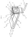
- the case 2 is provided with a concave portion 2d to store the nut 7.
- a major portion of the case 2 relevant to the invention alone is shown for ease of description, and other wiring conductors and structure bodies are omitted.
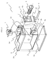
- the case 2 in which is embedded the wiring conductor 3 is shown by dividing the case 2 to the resin 2a in an upper part and the resin 2b in a lower part for ease of description.
- the case 2 is actually formed in such a manner that the resins 2a and 2b wrap the wiring conductor 3 by insert-molding and the resins 2a and 2b are indistinguishable.
- the wiring terminal surface 3a of the wiring conductor 3 is stored in the concave portion 2c of the case 2 with a clearance in between.
- the wiring terminal surface 3a may be of a structure by which the wiring terminal surface 3a is fixed by insert-molding using resin except for a portion bonded to the wiring terminal surface 4a of the outside wiring terminal 4.
- the concave portion 2d provided to the case 2 so as to store the nut 7 therein has a clearance large enough to insert and move the nut 7.
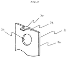
- it is sufficient that the hook-like protrusion 3b can press the nut 7 softly so that the nut 7 does not come out of the concave portion 2d and strength is not required.
- notch portions 3k are provided to the edge of the wiring terminal surface 3a at the bottom where the hook-like protrusion 3b is formed. Owing to this configuration, there can be achieved an advantage that not only is the hook-like protrusion 3b bent easily, but also the occurrence of strain in the wiring terminal surface 3a and the hook-like protrusion 3b is prevented during the processing.
- this embodiment is particularly effective when applied to a wiring conductor in a power-supply system, which is thick because of a need to flow a large current.
- connection structure of the wiring conductor of the first embodiment for the connection between the wiring terminal of the wiring conductor and the outside wiring terminal to which the flexible wiring is press-fit, by providing the hook-like protrusion to the edge of the wiring terminal surface of the wiring conductor and by pressing and locking the nut, which is the fastening member, with the hook-like protrusion, the need for positioning accuracy of the nut can be eliminated when the bolt is inserted and screwed into the nut. A fastening and bonding work therefore becomes easier. Hence, there can be achieved a significant advantage that work efficiency is enhanced and component costs and operational costs can be reduced.
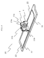
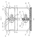
- Fig. 6 is a schematic perspective view showing a major portion of a connection structure of a wiring conductor of a second embodiment.
- Fig. 7 is a top view with a cross section taken along the line B-B of the connection structure of the wiring conductor.
- a difference from the connection structure of the wiring conductor of the first embodiment above is that in contrast to the first embodiment above in which one wiring terminal is a wiring terminal provided to the case or the wiring conductor on the wiring board and the other wiring terminal is a wiring terminal of the outside wiring terminal to which the flexible wiring is connected and these wiring terminals are interconnected, wiring terminals provided to wiring conductors on two wiring boards are interconnected in the second embodiment.
- a connection structure 40 of a wiring conductor has wiring terminal surfaces 43a and 53a formed in a convex shape by bending to be parallel to wiring conductors 43 and 53, respectively.
- the wiring terminal surface 43a of the wiring conductor 43 on the wiring board 42 and the wiring terminal surface 53a of the wiring conductor 53 on the wiring board 52 are connected.
- Two hook-like protrusions 43b are provided to an edge of the wiring terminal surface 43a and the nut 7 is pressed softly by one hook-like protrusion 43b.
- the wiring terminal surface 53a is pressed and locked as the other hook-like protrusion 43b and the edge of the wiring terminal surface 53a come into contact with each other.
- the wiring terminal surface 53a is thus substantially positioned and fixed. Then, by fastening the bolt 6 with nut 7 by screwing the former into the latter, the wiring conductor 43 on the wiring board 42 and the wiring conductor 53 on the wiring board 52 are electrically connected.
- connection structure of the wiring conductor of the second embodiment is for a case where wiring conductors provided to the case of the electronic device or on the wiring boards are interconnected, and by providing the hook-like protrusions to the edge of the wiring terminal surface of the wiring conductor, and by pressing and locking the other wiring terminal surface by the hook-like protrusions, the bolt is screwed into the nut, both of which are a fastening member.
- positional accuracy of the wiring terminal surfaces with respect to each other is not required, and a fastening and bonding work becomes easier. Accordingly, there can be achieved a significant advantage that work efficiency is enhanced and component costs and operational costs can be reduced.
Landscapes
- Coupling Device And Connection With Printed Circuit (AREA)
- Connections Arranged To Contact A Plurality Of Conductors (AREA)
- Multi-Conductor Connections (AREA)
- Manufacturing Of Electrical Connectors (AREA)
- Casings For Electric Apparatus (AREA)
- Insertion, Bundling And Securing Of Wires For Electric Apparatuses (AREA)
- Connections By Means Of Piercing Elements, Nuts, Or Screws (AREA)
Claims (5)
- Structure de connexion d'un conducteur de câblage qui interconnecte électriquement des surfaces de liaison (3a, 4a) de bornes de câblage de deux conducteurs de câblage (3, 4) en utilisant un élément de fixation qui inclut un boulon (6) et un écrou (7), caractérisée en ce que :au moins une borne de câblage (3) est munie d'une protubérance semblable à un crochet (3b) dans un bord de la surface de liaison (3a, 4a) ; etl'écrou est pressé et verrouillé par la protubérance semblable à un crochet (3b),dans laquelle les surfaces de liaison des bornes de câblage des deux conducteurs de câblage comprennent un trou de liaison pour insérer le boulon.
- Structure de connexion du conducteur de câblage selon la revendication 1, caractérisée en ce que :au moins le conducteur de câblage particulier (3) est moulé par insert avec un boîtier (2) d'un dispositif électronique.
- Structure de connexion du conducteur de câblage selon la revendication 1, caractérisée en ce que :au moins le conducteur de câblage particulier (13) est prévu sur une carte de câblage (12).
- Structure de connexion du conducteur de câblage selon l'une quelconque des revendications 1 à 3, caractérisée en ce que :la protubérance semblable à un crochet (3b) est formée du bord de la surface de liaison (3a) de la borne de câblage (3) par pliage.
- Structure de connexion du conducteur de câblage selon la revendication 4, caractérisée en ce que :une partie d'encoche (3k) est prévue sur le bord de la surface de liaison (3a) de la borne de câblage (3) à côté de la protubérance semblable à un crochet (3b).
Applications Claiming Priority (1)
| Application Number | Priority Date | Filing Date | Title |
|---|---|---|---|
| PCT/JP2011/073380 WO2013054400A1 (fr) | 2011-10-12 | 2011-10-12 | Structure de connexion de conducteur de câblage |
Publications (3)
| Publication Number | Publication Date |
|---|---|
| EP2768081A1 EP2768081A1 (fr) | 2014-08-20 |
| EP2768081A4 EP2768081A4 (fr) | 2015-06-24 |
| EP2768081B1 true EP2768081B1 (fr) | 2016-11-30 |
Family
ID=48081479
Family Applications (1)
| Application Number | Title | Priority Date | Filing Date |
|---|---|---|---|
| EP11874076.0A Active EP2768081B1 (fr) | 2011-10-12 | 2011-10-12 | Structure de connexion de conducteur de câblage |
Country Status (5)
| Country | Link |
|---|---|
| EP (1) | EP2768081B1 (fr) |
| JP (1) | JP5680213B2 (fr) |
| CN (1) | CN103858280B (fr) |
| IN (1) | IN2014CN03182A (fr) |
| WO (1) | WO2013054400A1 (fr) |
Families Citing this family (3)
| Publication number | Priority date | Publication date | Assignee | Title |
|---|---|---|---|---|
| JP5847131B2 (ja) * | 2013-07-09 | 2016-01-20 | 古河電気工業株式会社 | コネクタ |
| DE102016110050B4 (de) * | 2016-05-31 | 2020-01-23 | Endress+Hauser SE+Co. KG | Steck-Verbindung zur elektrischen Kontaktierung einer Leiterplatte |
| JP7262253B2 (ja) * | 2019-03-13 | 2023-04-21 | 日本精機株式会社 | 電子部品モジュール、電子部品モジュールと筐体との取付構造及びこれを備えた制御装置 |
Family Cites Families (7)
| Publication number | Priority date | Publication date | Assignee | Title |
|---|---|---|---|---|
| US1798812A (en) * | 1928-10-06 | 1931-03-31 | J H Rosenbeck & Sons | Electric terminal |
| US2398433A (en) * | 1944-03-18 | 1946-04-16 | Aircraft Marine Prod Inc | Electrical connector |
| FR1226070A (fr) * | 1959-05-27 | 1960-07-08 | Prise de courant basse tension et interrupteur associé | |
| JP3371359B2 (ja) * | 1997-07-10 | 2003-01-27 | 矢崎総業株式会社 | 端子の接続固定構造 |
| CN2543223Y (zh) * | 2002-04-08 | 2003-04-02 | 台湾神户电池股份有限公司 | 具有螺帽定位装置的端子 |
| JP2009043730A (ja) * | 2003-02-07 | 2009-02-26 | Fujitsu Ltd | 電源供給端子、導体部材付き電子部品及び該電源供給端子を備えた構造体 |
| JP2010027410A (ja) * | 2008-07-21 | 2010-02-04 | Shang Tsai Wu | 端子台の構造 |
-
2011
- 2011-10-12 WO PCT/JP2011/073380 patent/WO2013054400A1/fr active Application Filing
- 2011-10-12 IN IN3182CHN2014 patent/IN2014CN03182A/en unknown
- 2011-10-12 JP JP2013538358A patent/JP5680213B2/ja active Active
- 2011-10-12 EP EP11874076.0A patent/EP2768081B1/fr active Active
- 2011-10-12 CN CN201180074096.0A patent/CN103858280B/zh active Active
Non-Patent Citations (1)
| Title |
|---|
| None * |
Also Published As
| Publication number | Publication date |
|---|---|
| CN103858280A (zh) | 2014-06-11 |
| CN103858280B (zh) | 2019-04-23 |
| IN2014CN03182A (fr) | 2015-07-03 |
| WO2013054400A1 (fr) | 2013-04-18 |
| JP5680213B2 (ja) | 2015-03-04 |
| EP2768081A4 (fr) | 2015-06-24 |
| EP2768081A1 (fr) | 2014-08-20 |
| JPWO2013054400A1 (ja) | 2015-03-30 |
Similar Documents
| Publication | Publication Date | Title |
|---|---|---|
| CN101615728B (zh) | 型材夹钳 | |
| US9391385B2 (en) | Dual compressive connector | |
| EP0680113B1 (fr) | Connecteur électrique pour conducteur électrique | |
| US8269116B2 (en) | Circuit board case with electric connector and electronic unit provided with the same | |
| EP1701415A2 (fr) | Connecteur ayant des composants électroniques incorporés et faisceau de câblage | |
| CN103107429B (zh) | 夹紧元件 | |
| CN204167536U (zh) | 导线连接结构及使用该连接结构的电子设备 | |
| CN109075308B (zh) | 连接模块 | |
| US8550854B2 (en) | Edge connector | |
| EP2871721B1 (fr) | Structure de connexion entre un contact et un substrat | |
| EP2768081B1 (fr) | Structure de connexion de conducteur de câblage | |
| WO2018193347A1 (fr) | Dispositif connecteur avec connecteur et procédé d'assemblage | |
| EP2852264B1 (fr) | Module électronique avec une connexion à entrée latérale | |
| EP2622695B1 (fr) | Un connecteur pour connecter électriquement deux plaques | |
| JP4774062B2 (ja) | 銅バーの取付構造 | |
| JP2018182494A (ja) | アンテナ取付装置、アンテナ装置の取付方法 | |
| US20090117760A1 (en) | Terminal connecting structure | |
| US11005197B2 (en) | Control unit having press-fit structure | |
| JP7092729B2 (ja) | 端子、及び、端子と被取付面との組付構造 | |
| CN114188903B (zh) | 电气接线盒 | |
| EP4235975A1 (fr) | Fiche, connecteur et réceptacle | |
| JP2024024342A (ja) | アース端子、端子取付け構造 | |
| JP4403951B2 (ja) | 電子機器 | |
| JP2006148011A (ja) | 基板に対する電気素子の取付構造 | |
| CN115954697A (zh) | 连接器 |
Legal Events
| Date | Code | Title | Description |
|---|---|---|---|
| PUAI | Public reference made under article 153(3) epc to a published international application that has entered the european phase |
Free format text: ORIGINAL CODE: 0009012 |
|
| 17P | Request for examination filed |
Effective date: 20140227 |
|
| AK | Designated contracting states |
Kind code of ref document: A1 Designated state(s): AL AT BE BG CH CY CZ DE DK EE ES FI FR GB GR HR HU IE IS IT LI LT LU LV MC MK MT NL NO PL PT RO RS SE SI SK SM TR |
|
| DAX | Request for extension of the european patent (deleted) | ||
| REG | Reference to a national code |
Ref country code: DE Ref legal event code: R079 Ref document number: 602011033038 Country of ref document: DE Free format text: PREVIOUS MAIN CLASS: H01R0009220000 Ipc: H01R0004300000 |
|
| RA4 | Supplementary search report drawn up and despatched (corrected) |
Effective date: 20150527 |
|
| RIC1 | Information provided on ipc code assigned before grant |
Ipc: H01R 11/26 20060101ALN20150520BHEP Ipc: H01R 4/30 20060101AFI20150520BHEP Ipc: H01R 12/53 20110101ALN20150520BHEP Ipc: H01R 4/34 20060101ALN20150520BHEP |
|
| GRAP | Despatch of communication of intention to grant a patent |
Free format text: ORIGINAL CODE: EPIDOSNIGR1 |
|
| INTG | Intention to grant announced |
Effective date: 20160622 |
|
| GRAS | Grant fee paid |
Free format text: ORIGINAL CODE: EPIDOSNIGR3 |
|
| GRAA | (expected) grant |
Free format text: ORIGINAL CODE: 0009210 |
|
| AK | Designated contracting states |
Kind code of ref document: B1 Designated state(s): AL AT BE BG CH CY CZ DE DK EE ES FI FR GB GR HR HU IE IS IT LI LT LU LV MC MK MT NL NO PL PT RO RS SE SI SK SM TR |
|
| REG | Reference to a national code |
Ref country code: CH Ref legal event code: EP Ref country code: GB Ref legal event code: FG4D |
|
| REG | Reference to a national code |
Ref country code: AT Ref legal event code: REF Ref document number: 850602 Country of ref document: AT Kind code of ref document: T Effective date: 20161215 |
|
| REG | Reference to a national code |
Ref country code: IE Ref legal event code: FG4D |
|
| REG | Reference to a national code |
Ref country code: DE Ref legal event code: R096 Ref document number: 602011033038 Country of ref document: DE |
|
| PG25 | Lapsed in a contracting state [announced via postgrant information from national office to epo] |
Ref country code: LV Free format text: LAPSE BECAUSE OF FAILURE TO SUBMIT A TRANSLATION OF THE DESCRIPTION OR TO PAY THE FEE WITHIN THE PRESCRIBED TIME-LIMIT Effective date: 20161130 |
|
| REG | Reference to a national code |
Ref country code: LT Ref legal event code: MG4D |
|
| REG | Reference to a national code |
Ref country code: NL Ref legal event code: MP Effective date: 20161130 |
|
| REG | Reference to a national code |
Ref country code: AT Ref legal event code: MK05 Ref document number: 850602 Country of ref document: AT Kind code of ref document: T Effective date: 20161130 |
|
| PG25 | Lapsed in a contracting state [announced via postgrant information from national office to epo] |
Ref country code: LT Free format text: LAPSE BECAUSE OF FAILURE TO SUBMIT A TRANSLATION OF THE DESCRIPTION OR TO PAY THE FEE WITHIN THE PRESCRIBED TIME-LIMIT Effective date: 20161130 Ref country code: SE Free format text: LAPSE BECAUSE OF FAILURE TO SUBMIT A TRANSLATION OF THE DESCRIPTION OR TO PAY THE FEE WITHIN THE PRESCRIBED TIME-LIMIT Effective date: 20161130 Ref country code: GR Free format text: LAPSE BECAUSE OF FAILURE TO SUBMIT A TRANSLATION OF THE DESCRIPTION OR TO PAY THE FEE WITHIN THE PRESCRIBED TIME-LIMIT Effective date: 20170301 Ref country code: NO Free format text: LAPSE BECAUSE OF FAILURE TO SUBMIT A TRANSLATION OF THE DESCRIPTION OR TO PAY THE FEE WITHIN THE PRESCRIBED TIME-LIMIT Effective date: 20170228 |
|
| PG25 | Lapsed in a contracting state [announced via postgrant information from national office to epo] |
Ref country code: ES Free format text: LAPSE BECAUSE OF FAILURE TO SUBMIT A TRANSLATION OF THE DESCRIPTION OR TO PAY THE FEE WITHIN THE PRESCRIBED TIME-LIMIT Effective date: 20161130 Ref country code: FI Free format text: LAPSE BECAUSE OF FAILURE TO SUBMIT A TRANSLATION OF THE DESCRIPTION OR TO PAY THE FEE WITHIN THE PRESCRIBED TIME-LIMIT Effective date: 20161130 Ref country code: RS Free format text: LAPSE BECAUSE OF FAILURE TO SUBMIT A TRANSLATION OF THE DESCRIPTION OR TO PAY THE FEE WITHIN THE PRESCRIBED TIME-LIMIT Effective date: 20161130 Ref country code: HR Free format text: LAPSE BECAUSE OF FAILURE TO SUBMIT A TRANSLATION OF THE DESCRIPTION OR TO PAY THE FEE WITHIN THE PRESCRIBED TIME-LIMIT Effective date: 20161130 Ref country code: PT Free format text: LAPSE BECAUSE OF FAILURE TO SUBMIT A TRANSLATION OF THE DESCRIPTION OR TO PAY THE FEE WITHIN THE PRESCRIBED TIME-LIMIT Effective date: 20170330 Ref country code: AT Free format text: LAPSE BECAUSE OF FAILURE TO SUBMIT A TRANSLATION OF THE DESCRIPTION OR TO PAY THE FEE WITHIN THE PRESCRIBED TIME-LIMIT Effective date: 20161130 Ref country code: PL Free format text: LAPSE BECAUSE OF FAILURE TO SUBMIT A TRANSLATION OF THE DESCRIPTION OR TO PAY THE FEE WITHIN THE PRESCRIBED TIME-LIMIT Effective date: 20161130 |
|
| PG25 | Lapsed in a contracting state [announced via postgrant information from national office to epo] |
Ref country code: NL Free format text: LAPSE BECAUSE OF FAILURE TO SUBMIT A TRANSLATION OF THE DESCRIPTION OR TO PAY THE FEE WITHIN THE PRESCRIBED TIME-LIMIT Effective date: 20161130 |
|
| PG25 | Lapsed in a contracting state [announced via postgrant information from national office to epo] |
Ref country code: EE Free format text: LAPSE BECAUSE OF FAILURE TO SUBMIT A TRANSLATION OF THE DESCRIPTION OR TO PAY THE FEE WITHIN THE PRESCRIBED TIME-LIMIT Effective date: 20161130 Ref country code: DK Free format text: LAPSE BECAUSE OF FAILURE TO SUBMIT A TRANSLATION OF THE DESCRIPTION OR TO PAY THE FEE WITHIN THE PRESCRIBED TIME-LIMIT Effective date: 20161130 Ref country code: CZ Free format text: LAPSE BECAUSE OF FAILURE TO SUBMIT A TRANSLATION OF THE DESCRIPTION OR TO PAY THE FEE WITHIN THE PRESCRIBED TIME-LIMIT Effective date: 20161130 Ref country code: SK Free format text: LAPSE BECAUSE OF FAILURE TO SUBMIT A TRANSLATION OF THE DESCRIPTION OR TO PAY THE FEE WITHIN THE PRESCRIBED TIME-LIMIT Effective date: 20161130 Ref country code: RO Free format text: LAPSE BECAUSE OF FAILURE TO SUBMIT A TRANSLATION OF THE DESCRIPTION OR TO PAY THE FEE WITHIN THE PRESCRIBED TIME-LIMIT Effective date: 20161130 |
|
| PG25 | Lapsed in a contracting state [announced via postgrant information from national office to epo] |
Ref country code: SM Free format text: LAPSE BECAUSE OF FAILURE TO SUBMIT A TRANSLATION OF THE DESCRIPTION OR TO PAY THE FEE WITHIN THE PRESCRIBED TIME-LIMIT Effective date: 20161130 Ref country code: BE Free format text: LAPSE BECAUSE OF FAILURE TO SUBMIT A TRANSLATION OF THE DESCRIPTION OR TO PAY THE FEE WITHIN THE PRESCRIBED TIME-LIMIT Effective date: 20161130 Ref country code: BG Free format text: LAPSE BECAUSE OF FAILURE TO SUBMIT A TRANSLATION OF THE DESCRIPTION OR TO PAY THE FEE WITHIN THE PRESCRIBED TIME-LIMIT Effective date: 20170228 Ref country code: IT Free format text: LAPSE BECAUSE OF FAILURE TO SUBMIT A TRANSLATION OF THE DESCRIPTION OR TO PAY THE FEE WITHIN THE PRESCRIBED TIME-LIMIT Effective date: 20161130 |
|
| REG | Reference to a national code |
Ref country code: DE Ref legal event code: R097 Ref document number: 602011033038 Country of ref document: DE |
|
| REG | Reference to a national code |
Ref country code: FR Ref legal event code: PLFP Year of fee payment: 7 |
|
| PLBE | No opposition filed within time limit |
Free format text: ORIGINAL CODE: 0009261 |
|
| STAA | Information on the status of an ep patent application or granted ep patent |
Free format text: STATUS: NO OPPOSITION FILED WITHIN TIME LIMIT |
|
| 26N | No opposition filed |
Effective date: 20170831 |
|
| PG25 | Lapsed in a contracting state [announced via postgrant information from national office to epo] |
Ref country code: SI Free format text: LAPSE BECAUSE OF FAILURE TO SUBMIT A TRANSLATION OF THE DESCRIPTION OR TO PAY THE FEE WITHIN THE PRESCRIBED TIME-LIMIT Effective date: 20161130 |
|
| PG25 | Lapsed in a contracting state [announced via postgrant information from national office to epo] |
Ref country code: MC Free format text: LAPSE BECAUSE OF FAILURE TO SUBMIT A TRANSLATION OF THE DESCRIPTION OR TO PAY THE FEE WITHIN THE PRESCRIBED TIME-LIMIT Effective date: 20161130 |
|
| REG | Reference to a national code |
Ref country code: CH Ref legal event code: PL |
|
| GBPC | Gb: european patent ceased through non-payment of renewal fee |
Effective date: 20171012 |
|
| REG | Reference to a national code |
Ref country code: IE Ref legal event code: MM4A |
|
| PG25 | Lapsed in a contracting state [announced via postgrant information from national office to epo] |
Ref country code: LU Free format text: LAPSE BECAUSE OF NON-PAYMENT OF DUE FEES Effective date: 20171012 Ref country code: CH Free format text: LAPSE BECAUSE OF NON-PAYMENT OF DUE FEES Effective date: 20171031 Ref country code: LI Free format text: LAPSE BECAUSE OF NON-PAYMENT OF DUE FEES Effective date: 20171031 Ref country code: GB Free format text: LAPSE BECAUSE OF NON-PAYMENT OF DUE FEES Effective date: 20171012 |
|
| REG | Reference to a national code |
Ref country code: FR Ref legal event code: PLFP Year of fee payment: 8 |
|
| PG25 | Lapsed in a contracting state [announced via postgrant information from national office to epo] |
Ref country code: MT Free format text: LAPSE BECAUSE OF NON-PAYMENT OF DUE FEES Effective date: 20171012 |
|
| PG25 | Lapsed in a contracting state [announced via postgrant information from national office to epo] |
Ref country code: IE Free format text: LAPSE BECAUSE OF NON-PAYMENT OF DUE FEES Effective date: 20171012 |
|
| REG | Reference to a national code |
Ref country code: DE Ref legal event code: R084 Ref document number: 602011033038 Country of ref document: DE |
|
| PG25 | Lapsed in a contracting state [announced via postgrant information from national office to epo] |
Ref country code: HU Free format text: LAPSE BECAUSE OF FAILURE TO SUBMIT A TRANSLATION OF THE DESCRIPTION OR TO PAY THE FEE WITHIN THE PRESCRIBED TIME-LIMIT; INVALID AB INITIO Effective date: 20111012 |
|
| PG25 | Lapsed in a contracting state [announced via postgrant information from national office to epo] |
Ref country code: CY Free format text: LAPSE BECAUSE OF NON-PAYMENT OF DUE FEES Effective date: 20161130 |
|
| PG25 | Lapsed in a contracting state [announced via postgrant information from national office to epo] |
Ref country code: MK Free format text: LAPSE BECAUSE OF FAILURE TO SUBMIT A TRANSLATION OF THE DESCRIPTION OR TO PAY THE FEE WITHIN THE PRESCRIBED TIME-LIMIT Effective date: 20161130 |
|
| PG25 | Lapsed in a contracting state [announced via postgrant information from national office to epo] |
Ref country code: TR Free format text: LAPSE BECAUSE OF FAILURE TO SUBMIT A TRANSLATION OF THE DESCRIPTION OR TO PAY THE FEE WITHIN THE PRESCRIBED TIME-LIMIT Effective date: 20161130 |
|
| PG25 | Lapsed in a contracting state [announced via postgrant information from national office to epo] |
Ref country code: AL Free format text: LAPSE BECAUSE OF FAILURE TO SUBMIT A TRANSLATION OF THE DESCRIPTION OR TO PAY THE FEE WITHIN THE PRESCRIBED TIME-LIMIT Effective date: 20161130 Ref country code: IS Free format text: LAPSE BECAUSE OF FAILURE TO SUBMIT A TRANSLATION OF THE DESCRIPTION OR TO PAY THE FEE WITHIN THE PRESCRIBED TIME-LIMIT Effective date: 20170330 |
|
| PGFP | Annual fee paid to national office [announced via postgrant information from national office to epo] |
Ref country code: FR Payment date: 20220908 Year of fee payment: 12 |
|
| PGFP | Annual fee paid to national office [announced via postgrant information from national office to epo] |
Ref country code: DE Payment date: 20220621 Year of fee payment: 12 |
|
| P01 | Opt-out of the competence of the unified patent court (upc) registered |
Effective date: 20230512 |