EP2767404B1 - Bilderzeugungsvorrichtung, Verfahren zur Unterbrechung des Betriebs und Aufzeichnungsmedium mit Speicherung eines Programms zur Unterbrechung des Betriebs - Google Patents
Bilderzeugungsvorrichtung, Verfahren zur Unterbrechung des Betriebs und Aufzeichnungsmedium mit Speicherung eines Programms zur Unterbrechung des Betriebs Download PDFInfo
- Publication number
- EP2767404B1 EP2767404B1 EP14154595.4A EP14154595A EP2767404B1 EP 2767404 B1 EP2767404 B1 EP 2767404B1 EP 14154595 A EP14154595 A EP 14154595A EP 2767404 B1 EP2767404 B1 EP 2767404B1
- Authority
- EP
- European Patent Office
- Prior art keywords
- unit
- stop
- image forming
- image processing
- forcibly
- Prior art date
- Legal status (The legal status is an assumption and is not a legal conclusion. Google has not performed a legal analysis and makes no representation as to the accuracy of the status listed.)
- Active
Links
Images




Classifications
-
- B—PERFORMING OPERATIONS; TRANSPORTING
- B41—PRINTING; LINING MACHINES; TYPEWRITERS; STAMPS
- B41J—TYPEWRITERS; SELECTIVE PRINTING MECHANISMS, i.e. MECHANISMS PRINTING OTHERWISE THAN FROM A FORME; CORRECTION OF TYPOGRAPHICAL ERRORS
- B41J15/00—Devices or arrangements of selective printing mechanisms, e.g. ink-jet printers or thermal printers, specially adapted for supporting or handling copy material in continuous form, e.g. webs
- B41J15/04—Supporting, feeding, or guiding devices; Mountings for web rolls or spindles
-
- B—PERFORMING OPERATIONS; TRANSPORTING
- B41—PRINTING; LINING MACHINES; TYPEWRITERS; STAMPS
- B41J—TYPEWRITERS; SELECTIVE PRINTING MECHANISMS, i.e. MECHANISMS PRINTING OTHERWISE THAN FROM A FORME; CORRECTION OF TYPOGRAPHICAL ERRORS
- B41J11/00—Devices or arrangements of selective printing mechanisms, e.g. ink-jet printers or thermal printers, for supporting or handling copy material in sheet or web form
- B41J11/36—Blanking or long feeds; Feeding to a particular line, e.g. by rotation of platen or feed roller
- B41J11/42—Controlling printing material conveyance for accurate alignment of the printing material with the printhead; Print registering
-
- B—PERFORMING OPERATIONS; TRANSPORTING
- B41—PRINTING; LINING MACHINES; TYPEWRITERS; STAMPS
- B41J—TYPEWRITERS; SELECTIVE PRINTING MECHANISMS, i.e. MECHANISMS PRINTING OTHERWISE THAN FROM A FORME; CORRECTION OF TYPOGRAPHICAL ERRORS
- B41J2/00—Typewriters or selective printing mechanisms characterised by the printing or marking process for which they are designed
- B41J2/315—Typewriters or selective printing mechanisms characterised by the printing or marking process for which they are designed characterised by selective application of heat to a heat sensitive printing or impression-transfer material
- B41J2/32—Typewriters or selective printing mechanisms characterised by the printing or marking process for which they are designed characterised by selective application of heat to a heat sensitive printing or impression-transfer material using thermal heads
Definitions
- the present invention relates to an image forming apparatus, method of stopping operation, and recording medium storing a program for stopping operation.
- image processing apparatuses such as printers and facsimiles used for outputting the computerized information and scanners used for computerizing documents have become indispensable.
- these image processing apparatuses are configured as multifunctional peripherals (MFPs) that can be used as printers, facsimiles, scanners, or copiers by implementing an image pickup function, image forming function, and communication function, etc.
- MFPs multifunctional peripherals
- image processing apparatuses in image forming apparatuses used for outputting computerized images, various configurations such as an image forming mechanism that performs forming and outputting images and a feeding mechanism that feeds paper as a medium on which images are output are operating mechanically. Therefore, regarding control of stopping operations of the apparatus, various processes are configured to prevent the apparatus from causing troubles.
- JP-2012-086450-A proposes an image forming apparatus in which a drawing process module and an image process module are connected serially.
- a stopping output destination determining unit of the image forming apparatus determines whether or not the latter image process module is stoppable . If the image process module is unstoppable in case of receiving the forcibly stop request, the image process module finishes processing after performing image processing using pixel data of predetermined color value for the number of unprocessed pixels. By contrast, if the image process module is stoppable in case of receiving the forcibly stop request, the image process module is stopped immediately to fulfill an urgent stop request quickly.
- EP-A-1624665 discloses the preamble of claims 1 and 9.
- An example embodiment of the present invention provides an image forming apparatus according to claim 1.
- An example embodiment of the present invention includes a method according to claim 9.
- FIG. 1 is a block diagram illustrating a hardware configuration of the image forming apparatus.
- the information processing apparatus in this embodiment includes an engine that performs forming an image in addition to the same configuration as information processing apparatuses such as a general server or a personal computer (PC) etc.
- PC personal computer
- a Central Processing Unit (CPU) 10, a Random Access Memory (RAM) 11, a Read Only Memory (ROM) 12, an engine 13, a hard disk drive (HDD) 14, and an interface (I/F) 15 are connected with each other via a bus 18.
- a Liquid Crystal Display(LCD) 16 and an operational unit 17 are connected to the I/F 15.
- the CPU 10 is a processor and controls the whole operation of the information processing apparatus.
- the RAM 11 is a volatile storage device that can read/write information at high speed and is used as a work area when the CPU 10 processes information.
- the ROM 12 is a read-only nonvolatile storage device and stores programs such as firmware.
- the engine 13 performs forming and processing an image actually in the image forming apparatus 1.
- the HDD 14 is a nonvolatile storage device that can read/write information and stores an operating system (OS), various control programs, and application programs etc.
- the I/F 15 connects the bus 18 with various hardware and network etc. and controls them.
- the LCD 16 is a visual user interface to check status of the image forming apparatus 1.
- the operational unit 17 is a user interface such as a keyboard, mouse, various hardware buttons, and touch panel to input information to the image forming apparatus 1.
- FIG. 2 is a block diagram illustrating a functional configuration of the image forming apparatus 1.
- the image forming apparatus 1 includes a controller 20, an Auto Document Feeder (ADF) 21, a scanner unit 22, a paper output tray 23, a display panel 24, a paper feeder 25, a print engine 26, a paper output tray 27, and a network I/F 28.
- the image forming apparatus 1 includes an inkjet forming unit that forms an image by an inkjet recording method that uses roll sheet as an image forming mechanism.
- the paper feeder 25 and the print engine 26 are included in an inkjet forming unit 100.
- the ADF 21 and the scanner unit 22 are included in an image scanning unit 200.
- the controller 20 includes a main controller 30, an engine controller 31, an input/output controller 32, an image processor 33, and an operational display controller 34.
- the image forming apparatus 1 in this embodiment is constructed as the MFP that includes the scanner unit 22 and the print engine 26.
- solid arrows indicate electrical connections, and dashed arrows indicate flow of paper.
- the display panel 24 is both an output interface that displays status of the image forming apparatus 1 visually and an input interface (operational unit) to operate the image forming apparatus 1 directly or input information to the image forming apparatus 1.
- the network I/F 28 is an interface that the image forming apparatus 1 communicates with other apparatuses via a network, and Ethernet and Universal Serial Bus (USB) interface are used for the network I/F 18.
- the controller 20 combines software (including an operation stopping program that executes an operation stopping method for the image forming apparatus 1) and hardware.
- control programs such as firmware stored in nonvolatile storage devices such as the ROM 12, nonvolatile memory devices, the HDD 14, and optical disks are loaded into volatile memory device such as the RAM 11 (hereinafter referred to as "memory"), and the software controlling unit is implemented by executing operations by the CPU 10 in accordance with the programs.
- the controller 20 is constructed of the software controlling unit and hardware such as integrated circuits.
- the controller 20 functions as a controller that controls the whole part of the image forming apparatus 1.
- the main controller 30 controls each unit included in the controller 20 and sends commands to each unit in the controller 20.
- the engine controller 31 controls and drives the print engine 26, the ADF 21, and the scanner unit 22 etc.
- the input/output controller 32 inputs signals and commands input via the network I/F 28 to the main controller 30.
- the main controller 30 controls the input/output controller 32 and accesses other apparatuses via the network I/F 18.
- the image processor 33 generates drawing information based on print information included in an input print job under the control of the main controller 30.
- the drawing information is information that the print engine 26 as an image forming unit draws as an image to be formed in an image forming operation.
- the print information included in the print job is image information converted by a printer driver installed in the image processing apparatus such as the PC to a format recognizable by the image forming apparatus 1.
- the operational display controller 34 displays information on the display panel 24 and reports information input via the display panel 24 to the main controller 30. That is, the main controller 30 and the operational display controller 34 consist of an operation acceptance unit.
- the input output controller 32 receives a print job via the network I/F 28.
- the input/output controller 32 transfers the received print job to the main controller 30.
- the main controller 30 After receiving the print job, the main controller 30 generates the drawing information based on the document information and image information included in the print job by controlling the image generator 33.
- the engine controller 31 executes forming an image on roll sheet carried from the paper feeder 25 in the inkjet forming unit 100 based on the generated drawing information. That is, the inkjet forming unit 100 functions as the print engine 26. After the print engine 26 forms the image on the roll sheet, the roll sheet is ejected on the paper output tray 27.
- the operational display controller 34 or the input/output controller 32 transfers a signal to execute scanning to the main controller 30.
- the main controller 30 controls the engine controller 31 based on the received signal to execute scanning.
- the engine controller 31 drives the ADF 21 and carries a document to be scanned set on the ADF 21 to the scanner unit 22.
- the engine controller 31 drives the scanner unit 22 and scans the document carried from the ADF 21. If the document is not set on the ADF 21 and the document is set on the scanner unit 22 directly, the scanner unit 22 scans the set document under the control of the engine controller 31. That is, the ADF 21 and the scanner unit 22 functions as an image pickup engine.
- an image pickup device such as CCD included in the scanner unit 22 scans the document optically, and image pickup information is generated based on the optical information.
- the engine controller 31 transfers the image pickup information generated by the scanner unit 22 to the image processor 33.
- the image processor 33 generates the image information based on the image pickup information received from the engine controller 31 under the control of the main controller 30.
- the image information generated by the image processor 33 is either stored in the HDD 14 etc. as is or transferred to an external apparatus by the input/output controller 32 via the network I/F 18 depending on the user instruction.
- the image processor 33 If the image forming apparatus 1 functions as a copier, the image processor 33 generates the drawing information based on either the image pickup information received from the scanner unit 22 by the engine controller 31 or the image information generated by the image processor 33. Similarly as the printer operation, the engine controller 31 drives the print engine 26 based on the drawing information.
- FIG. 3 is a block diagram illustrating a functional configuration for the operation stopping process.
- the operational unit 17 includes a trigger to stop normally input unit 17a for inputting an instruction to cancel a job that waits for executing, a trigger to stop forcibly input unit 17b for inputting an instruction to stop a job executed currently, and a trigger cancelation unit 17c for inputting an instruction to interrupt an operation to stop the job executed currently (shown as "trigger cancellation" in FIG. 3 ).
- the trigger to stop normally input unit 17a can be configured by using either a software button displayed on the display panel 24 or a hardware button mounted on a case surface of the image forming apparatus 1.
- the trigger to stop normally input unit 17a can be configured by selecting job cancelation on a confirmation screen of a print job.
- the trigger to stop forcibly input unit 17b is configured by using a software button in a screen displayed on the display panel 24 after the trigger to stop normally input unit 17a is operated.
- the trigger cancelation unit 17c is configured by using a software button in a screen displayed during forcibly stopping operation. If the trigger cancelation unit 17c is operated, the image processing operation stopped normally or forcibly can be resumed.
- Timing of the input operation on the trigger to stop forcibly input unit 17b and the trigger cancelation unit 17c is controlled by configuring the trigger to stop forcibly input unit 17b and the trigger cancelation unit 17c using the software button in a screen and controlling timing of displaying the screen.
- the engine 13 (shown in FIG. 1 ) is included as an image processing unit.
- the engine 13 includes an image processing mechanical unit 13b as a mechanical configuration that realizes the image processing function and an image processing drive unit 13a that drives the image processing mechanical unit 13b.
- the image forming apparatus 1 in this embodiment includes a print engine 26 and an image scanning unit 200 as shown in FIG. 2 .
- the print engine 26 realizes formation and output of an image
- the image scanning unit 200 realizes a document scanning function.
- the print engine 26 includes an image formation driving unit 26a (also referred to as “plotter controller”) and an image forming unit 26b (also referred to as “plotter”) as an image processing mechanical unit.
- image formation driving unit 26a also referred to as “plotter controller”
- image forming unit 26b also referred to as “plotter”
- the image formation driving unit 26a consists of combination of software and hardware that controls operation of the image forming unit 26b.
- the image formation driving unit 26a stores a job that waits for being executed by the image forming unit 26b.
- the image forming unit 26b executes forming and outputting an image on a recording medium for images and includes paper carrying mechanism and printing mechanism.
- the image scanning unit 200 includes a scanning driver 200a (also referred to as “scanning unit controller”) and a scanning mechanism unit 200b.
- the scanning mechanism unit 200b is a mechanical configuration that realizes a document scanning function and image pickup information generating function.
- a document carrying mechanism in the ADF 21 and hardware that includes optical components such as an image sensor and light source in the scanning unit 22 correspond to the scanning mechanism unit 200b.
- the scanning driver 200a acquires image pickup information by driving the scanning mechanism unit 200b and consists of the scanning driver.
- the scanning driver 200a consists of combination of software and hardware and controls each part in the scanning mechanism unit 200b.
- the scanning driver 200a stores a job that waits for being executed by the scanning mechanism unit 200b.
- the image formation driving unit 26a and the scanning driver 200a are included in the image processing drive unit 13a, and the image forming unit 26b and the scanning mechanism unit 200b are included in the image processing mechanical unit 13b.
- the controller 20 includes a normal stop instruction unit 20a, a forcibly stop instruction unit 20b, a screen generator 20c, an operation acceptance unit 20d, and a stop target configuration unit 20e as a configuration for controlling normal stop operation and forcibly stop operation.
- the normal stop instruction unit 20a is electrically connected to units that store following job data (that is, each of the image formation driving unit 26a and the scanning mechanism unit 200b in FIG. 3 ).
- the screen generator 20c generates screens displayed on the display panel 24 in accordance with status executing normal stop operation and forcibly stop operation. Screens generated by the screen generator 20c will be described later in detail with the reference to FIG. 8 .
- the operation acceptance unit 20d acquires information in accordance with input operation on the trigger to stop normally input unit 17a and the trigger to stop forcibly input unit 17b (electric signal that indicates which one is operated, the trigger to stop normally input unit 17a or the trigger to stop forcibly input unit 17b) and generates and outputs a trigger signal in accordance with each input operation.
- the stop target configuration unit 20e configures that either or both of the print engine 26 or the image scanning unit 200 is stopped forcibly.
- the stop target configuration unit 20e is electrically connected to the forcibly stop instruction unit 20b, and the forcibly stop instruction unit 20b outputs an instruction necessary for stopping forcibly only to the unit configured by the stop target configuration unit 20e.
- the combination of the main controller 30 and the engine controller 31 consists of the normal stop instruction unit 20a and the forcibly stop instruction unit 20b, and the combination of the main controller 30 and the operational display controller 34 consists of the screen generator 20c, the operation acceptance unit 20d, and the stop target configuration unit 20e.
- the operation acceptance unit 20d acquires information in accordance with the input operation on the trigger to stop normally input unit 17a and generates the trigger to stop normally.
- the trigger to stop normally is output to the normal stop instruction unit 20a.
- the normal stop instruction unit 20a outputs a signal to instruct the image formation driving unit 26a to cancel the waiting job (that is, a signal to instruct to discard image information already acquired)
- the image formation driving unit 26a cancels the stored following job.
- the image formation driving unit 26a cancels drawing information of the following job stored in a line memory included in the image formation driving unit 26a.
- the normal stop instruction unit 20a outputs a signal to instruct the scanning driver 200a to stop carrying a document that waits for being scanned mounted on a paper feed tray (not shown in figures) included in the ADF 21, and the scanning driver 200a stops scanning the following document.
- the operation acceptance unit 20d acquires information in accordance with the input operation on the trigger to stop forcibly input unit 17b and generates the trigger to stop forcibly.
- the trigger to stop forcibly is output to the forcibly stop instruction unit 20b, After the forcibly stop instruction unit 20b outputs a signal to instruct the image forming unit 26b to stop executing the current job, the image forming unit 26b stops the current job(that is, the image forming unit 26b outputs a signal to execute operation in case of stopping supplying power).
- the image forming unit 26b includes a register to input an instruction to shut down (hereinafter referred to as "shutdown register").
- the forcibly stop instruction unit 20b rewrites a value of the shutdown register as a value of instructing to shut down. Accordingly, the image forming unit 26b performs the forcibly stop operation.
- the forcibly stop operation means that apparatus status is transitioned from a job executing status to another different status such as a waiting status without waiting for finishing the job. For example, the roll sheet is ejected forcibly in case of a skew operation.
- the forcibly stop instruction unit 20b outputs a signal to instruct the scanning mechanism unit 200b to stop, and the scanning mechanism unit 200b ejects a document that the ADF 21 is carrying forcibly and stops optical scanning by the scanning unit 22. Subsequently, the forcibly stop instruction unit 20b transitions the scanning mechanism unit 200b that includes units described above to the standby status.
- the job stored in the image formation driving unit 26a and the scanning drive unit 200a can be stopped by the trigger to stop normally. Furthermore, the job already passed to the image forming unit 20b and the scanning mechanism unit 200b can be stopped by the trigger to stop forcibly too. Consequently, the operation of the print engine 26 and the image scanner 200 can be stopped forcibly.
- the trigger to stop forcibly can finish all operation of the print engine 26 and the image scanner 200 by implementing the function to stop both the print engine 26 and the image scanner 200 forcibly.
- the trigger to stop forcibly can implement a function to stop only the image scanner 200 or only the print engine 26.
- the screen generator 20c can display a screen for configuring a target to stop forcibly on the display panel 24, and it can be configured that only the image scanner 200 is stopped, the print engine 26 is stopped, or both the image scanner 200 and the print engine 26 is stopped.
- the screen generator 20c and the operational unit 17 consist of a stop target configuration unit.
- FIG. 4 is a perspective diagram illustrating an exterior configuration of the inkjet forming apparatus
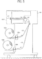
- FIG. 5 is a cross-sectional profile diagram illustrating the inkjet forming apparatus.
- the inkjet forming apparatus shown in FIG. 4 and FIG. 5 includes spool roller bearing mountings 101a and 101b.
- the spool roller bearing mountings 101a and 101b function as sheet supporting units that support an upper roll sheet 104a and a lower roll sheet 104b that unreel a sheet 110.
- the left side of the main unit of the apparatus 101 is the front side 101F
- the right side of the main unit of the apparatus 101 is the rear side in FIG. 4 .
- the main scanning direction Y perpendicular both the vertical direction Z and the anteroposterior direction X in FIG. 4 penetrates the page of FIG. 5
- the main scanning direction Y corresponds to the sheet width direction.
- a guide rod 118 and a guide rail 119 are spanned across side panels (not shown in figures) inside the main unit of the apparatus 101, and a carriage 120 is held on the guide rod 118 and the guide rail 119 movably in the main scanning direction Y.
- the carriage 120 includes liquid recording heads (not shown in figures) that discharge ink droplets whose colors are black (K), yellow (Y), magenta (M), and cyan (C).
- the carriage 120 includes a sensor that detects a carried sheet.
- Each liquid recording head includes sub tanks (not shown in figures) that supply ink to each liquid recording head integrally.
- a main scanning mechanism that moves and scans the carriage 120 in the main scanning direction Y includes a driving motor 121 mounted on one side of the main scanning direction Y (diagonally upward left in FIG. 4 ), a driving pulley 122 connected to an output shaft of the driving motor 121 and driven by the driving motor 121, a driven pulley 123 mounted on the other side of the main scanning direction Y (diagonally downward right in FIG. 4 ), and a belt member 124 that runs between the driving pulley 122 and the driven pulley 123.
- the driven pulley 123 is tensioned to the outside direction, that is, the direction getting away from the driving pulley 122 by a tension spring (not shown in figures).
- the belt member 124 pulls the carriage 120 into the main scanning direction Y since a part of the belt member 124 is held by a belt holding unit mounted on the back side of the carriage 120.
- An encoder sheet (not shown in figures) that detects the main scanning position of the carriage 120 is mounted along with the main scanning direction Y, and the encoder sheet is read by an encoder sensor (not shown in figures) mounted on the carriage 120.
- the sheet 110 unreeled and carried from the upper roll sheet 104a or the lower roll sheet 104b (described in detail later) is carried by a carrying unit (a pair of rollers 109a and 109b, a resistance roller 134, and a resistance pressure roller 135.
- the sheet 110 is carried in the sub-scanning direction perpendicular to the main scanning direction Y where the carriage 120 moves, that is, the sheet 110 is carried in the forward direction Xa among anteroposterior direction X in FIG. 4 intermittently.
- a maintenance recovery unit 125 that maintains and recovers each liquid recording head in the carriage 120 is mounted in the other side zone (diagonally downward right in FIG. 4 ). Furthermore, a main cartridge 126 that contains ink in each color to supply to the sub tank of each liquid recording head is mounted detachably to the main unit of the apparatus 101.
- a cutter 127 that cuts the sheet on which an image is recorded at a predetermined length is mounted.
- the cutter 127 is fixed on a wire and a timing belt that run between multiple pulleys.
- one of the multiple pulleys is connected to the driving motor, and the sheet is cut at the predetermined length by moving the wire and the timing belt by the driving motor via the pulley in the main scanning direction Y.
- FIG. 6 is a flowchart illustrating flow of a process performed by the image forming apparatus.
- a roll sheet or a cut sheet is prepared in S601.
- print settings are configured in S602. Instructing to start printing, e.g., pressing a hardware button to input starting printing, is included in configuring the print settings.
- scanning a document is also included in configuring the print settings.
- printing is executed in S603, and the printing finishes in S604. If it is necessary to wait for drying the printed surface (NO in S605), the sheet is dried in S606. After finishing drying the sheet, or if it is not necessary to wait for drying the printed surface (YES in S605), the sheet is cut and ejected in S607. If there is a following job (NO in S608), the process goes back to S603, and the next printing process is executed. If there is no following jobs (YES in S608), the process ends.
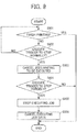
- FIG. 7 is a flowchart illustrating a stopping operation performed by the image forming apparatus as an embodiment of the present invention.
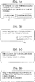
- FIG. 8A is a diagram illustrating a forcibly stop selection screen
- FIG. 8B is a diagram illustrating a forcibly stop execution screen
- FIG. 8C is a diagram illustrating an uncharged forcibly stop notification screen
- FIG. 8D is a diagram illustrating a charged forcibly stop notification screen.
- the normally stop command unit outputs a signal to command to cancel jobs that wait for being executed to the image formation driving unit 26a and the scan driving unit 200a.
- the image formation driving unit 26a and the scan driving unit 200a cancel jobs that wait for being executed in S703.
- the screen generator 20c displays a screen to select whether or not it is necessary to execute stopping forcibly (hereinafter referred to as "a forcibly stop selection screen") on the display panel 24 in S704.
- FIG. 8A is a diagram illustrating the forcibly stop selection screen.
- the forcibly stop selection screen includes a software button 801 that accepts inputting a command to execute stopping forcibly and a software button 802 that accepts inputting a command not to execute stopping forcibly.
- the software button 801 is the trigger to stop forcibly input unit 17b.
- the software button 801 is operated, and the trigger to stop forcibly is executed (YES in S705).
- the forcibly stop command unit 20b starts an operation to stop the job currently executed with the image forming unit 26b and the scan mechanical unit 200b in S706.
- the screen generator 20c displays a screen to report that the operation to stop forcibly is currently executed (hereinafter referred to as "a forcibly stop execution screen") on the display panel 24 in S707.
- FIG. 8B is a diagram illustrating the forcibly stop execution screen.
- the forcibly stop execution screen includes a software button 803 that accepts inputting a command to interrupt the operation to stop forcibly. After a resuming operation is executed by pressing the software button 803 (YES in S708), the normally stop command unit 20a outputs a signal to command to resume the stopped image processing operation to the image formation driving unit 26a and the scan driving unit 200a, and the forcibly stop command unit 20b outputs a signal to command to resume the stopped image processing operation to the image forming unit 26b and the scan mechanical unit 200b. Accordingly, the stopped units resume the job currently executed in S711, and the process ends after the job is finished. If the software button 803 is not operated (NO in S708), the job data currently executed is deleted in S710.
- the screen generator 20c displays a screen to report that the operation to stop forcibly finishes (hereinafter referred to as "a forcibly stop notification screen") on the display pane 24 in S708.
- a forcibly stop notification screen is a diagram illustrating an uncharged forcibly stop notification screen
- FIG. 8D is a diagram illustrating a charged forcibly stop notification screen. The screen shown in FIG. 8C is displayed if the job currently executed is finished on the way after the operation to stop forcibly.
- the trigger to stop normally input unit 17a and the trigger to stop forcibly input unit 17b are set separately in the above description.
- an operational unit a hardware button or a software button
- the trigger to stop normally and the trigger to stop forcibly can be input by one operation.
- timing of outputting the signal to command to stop forcibly by the forcibly stop command unit 20b can be delayed than timing of outputting the signal to command to stop normally by the normally stop command unit 20a to prevent inconvenience that a subsequent job is sent to the stopped image forming unit 26b because the subsequent job is stopped after the job currently executed is stopped.
- the image forming unit 26b If the trigger to stop forcibly is input while the printing operation is executed in S603, the image forming unit 26b aborts printing, stops waiting for drying sheet forcibly, cuts the sheet, and ejects the sheet. In addition, a cap is put on a liquid recording head (not shown in figures) in the carriage 120. If the trigger to stop forcibly is input while the sheet is drying in S606, the image forming unit 26b stops waiting for drying sheet forcibly, cut the sheet, and ejects the sheet.
- the job currently executed is stopped and the cap is put on the liquid recording head.
- the roll forming operation as the job currently executed is stopped, and the sheet is ejected out of the apparatus.
- the scanning operation as the job currently executed is stopped.
- the cap is put on the liquid recording head too.
- the process currently executed and the subsequent process are aborted forcibly, it is executed to cap and transition to the state in which image forming and outputting operation can be executed.
- any trigger becomes invalid.
- FIG. 9 is a flowchart illustrating a flow of stopping operation without a displaying process.
- an input device e.g., a hardware button
- the screen to input the trigger to stop forcibly becomes unnecessary.
- an input device to accept the trigger to stop normally is included on the case of the image forming apparatus 1 too. Under this assumption, the process shown in FIG. 9 is described below.
- the printing process is finished if the printing process was executed normally (YES in S901).
- the image forming apparatus 1 is in the status of waiting for the trigger to stop normally during the printing operation (NO in S901), and the image forming apparatus continues the printing operation until the trigger to stop normally is executed (NO in S902).
- the trigger to stop normally and the trigger to stop forcibly are input by the user operation.
- an irregular status of the image forming apparatus 1 e.g., irregular tension is generated due to paper jam of the roll sheet
- the image forming apparatus 1 can perform a stop operation autonomously without user operation in accordance with the status of the image forming apparatus 1 itself out of user recognition.
- inkjet method is used as the image forming mechanism.
- the key point in the example embodiments described above is the control of the forcibly stop operation during the printing job, and the type of the image forming mechanism is not limited to a specific method. That is, that can be applied to the image forming apparatus with various image forming mechanisms such as electrophotography method and thermal method, and similar effects can be achieved with them.
Landscapes
- Facsimiles In General (AREA)
- Accessory Devices And Overall Control Thereof (AREA)
- Control Or Security For Electrophotography (AREA)
Claims (10)
- Bilderzeugungsvorrichtung (1), die umfasst:eine mechanische Bildverarbeitungseinheit (26b, 200b), um eine Bildverarbeitungsfunktion zu realisieren;eine Bildverarbeitungsansteuerung (26a, 200a), um die mechanische Bildverarbeitungseinheit (26b, 200b) in Übereinstimmung mit einem Betriebszustand der Bilderzeugungsvorrichtung (1) anzusteuern;eine Bedienungsempfangseinheit (20d), um Informationen in Übereinstimmung mit einer Anwenderbedienung an einer Betriebseinheit (17) zu erfassen;eine Normalstopp-Befehlseinheit (20a), um ein Signal, das befiehlt, einen Bildverarbeitungsvorgang zu stoppen, an die Bildverarbeitungsansteuerung (26a, 200a) auszugeben, wenn sich die durch die Bedienungsempfangseinheit (20d) erfassten Informationen auf einen Normalstoppvorgang beziehen; undeine Zwangsstoppbefehlseinheit (20b), um ein Signal, das befiehlt, den derzeit ausgeführten Bildverarbeitungsvorgang zu stoppen, an die mechanische Bildverarbeitungseinheit (26b, 200b) auszugeben, wenn sich die durch die Bedienungsempfangseinheit (20d) erfassten Informationen auf einen Zwangsstoppvorgang beziehen;dadurch gekennzeichnet, dass:
die Bilderzeugungsvorrichtung (1) konfiguriert ist, einen unregelmäßigen Zustand der Bilderzeugungsvorrichtung (1) zu detektieren und einen Auslöser, um normal zu stoppen, oder einen Auslöser, um erzwungen zu stoppen, in Übereinstimmung mit dem Ergebnis der Detektion einzugeben. - Bilderzeugungsvorrichtung (1) nach Anspruch 1, wobei die mechanische Bildverarbeitungseinheit (26, 200b) eine Bilderzeugungseinheit (26b) ist, die ein Bild auf einem Aufzeichnungsmedium erzeugt, wobei die Bildverarbeitungsansteuerung (26a, 200a) eine Bilderzeugungsansteuerungseinheit (26a) ist, die Informationen des zu erzeugenden Bilds erfasst und die Bilderzeugungseinheit (26b) gemäß den erfassten Bildinformationen ansteuert,
wobei die Normalstopp-Befehlseinheit (20a) ein Signal ausgibt, dass der Bilderzeugungsansteuerungseinheit (26a) befiehlt, die erfassten Bildinformationen zu verwerfen, wenn die Bedienungsempfangseinheit (20d) Informationen bezüglich eines Normalstoppvorgangs erfasst, und
die Zwangsstoppbefehlseinheit (20b) ein Signal ausgibt, dass der Bilderzeugungseinheit (26b) befiehlt, einen Vorgang auszuführen, um eine Stromversorgung zu stoppen, wenn die Bedienungsempfangseinheit (20d) Informationen bezüglich eines Zwangsstoppvorgangs erfasst. - Bilderzeugungsvorrichtung (1) nach einem der Ansprüche 1 bis 2,
wobei der Zeitpunkt, zu dem die Zwangsstoppbefehlseinheit (20b) das Signal ausgibt, dass der mechanischen Bildverarbeitungseinheit (26b, 200b) befiehlt, den Bildverarbeitungsvorgang zu stoppen, nach dem Zeitpunkt liegt, wenn die Normalstopp-Befehlseinheit (20a) das Signal ausgibt, dass der Bildverarbeitungsansteuerung (26a, 200a) befiehlt, den Bildverarbeitungsvorgang zu stoppen. - Bilderzeugungsvorrichtung (1) nach Anspruch 3, wobei die Bedienungsempfangseinheit (20d) einen Zwangsstoppauswahlbildschirm anzeigt, der einen Auslöser enthält, um die Eingabeeinheit (17b) erzwungen zu stoppen, um einem Anwender zu erlauben, den Zwangsstoppvorgang einzugeben, nachdem die Normalstopp-Befehlseinheit (20a) ein Signal ausgibt, das der Bildverarbeitungsansteuerung (26a, 200a) befiehlt, den Bilderzeugungsvorgang zu stoppen.
- Bilderzeugungsvorrichtung (1) nach Anspruch 3, wobei die Bedienungsempfangseinheit (20d) Informationen bezüglich des Normalstoppvorgangs und Informationen bezüglich des Zwangsstoppvorgangs in Übereinstimmung mit einer Reihe von Bedienungen an der Betriebseinheit (17) erfasst.
- Bilderzeugungsvorrichtung (1) nach einem der Ansprüche 1 bis 5, wobei die Bedienungsempfangseinheit (20d) ein Signal, um die Bildverarbeitungsansteuerung (26a, 200a) anzuweisen, den Bildverarbeitungsvorgang wiederaufzunehmen, und ein Signal, um die mechanische Bildverarbeitungseinheit (26, 200b) anzuweisen, den Bildverarbeitungsvorgang wiederaufzunehmen, ausgibt, wenn die Bedienungsempfangseinheit (20d) Informationen bezüglich des Vorgangs, den Bildverarbeitungsvorgang, der angewiesen wurde, zu stoppen, wiederaufzunehmen, erfasst.
- Bilderzeugungsvorrichtung (1) nach einem der Ansprüche 1 bis 6, wobei die mechanische Bildverarbeitungseinheit (26b, 200b) eine mechanische Abtasteinheit (200b) ist, die ein Dokument abtastet, um Bildinformationen zu erzeugen, die Bildverarbeitungsansteuerung (26a, 200a) eine Abtastansteuerungseinheit (200a) ist, die die mechanische Abtasteinheit (200b) ansteuert und die Bildinformationen erfasst,
die Normalstopp-Befehlseinheit (20a) ein Signal ausgibt, das die Abtastansteuerungseinheit (200a) anweist, zu stoppen, ein abzutastendes Dokument zu befördern, wenn die Bedienungsempfangseinheit (20d) Informationen bezüglich des Normalstoppvorgangs erfasst, und
die Zwangsstoppbefehlseinheit (20b) ein Signal ausgibt, dass die mechanische Abtasteinheit (200b) anweist, einen Vorgang des Stoppens des Lieferns von Strom auszuführen, wenn die Bedienungsempfangseinheit (20d) Informationen bezüglich des Zwangsstoppvorgangs erfasst. - Bilderzeugungsvorrichtung (1) nach Anspruch 7, die ferner umfasst:
eine Einheit zur Konfiguration eines zu stoppenden Ziels (20e), um zu konfigurieren, dass die mechanische Bildverarbeitungseinheit (26, 200b) erzwungen gestoppt wird, wobei die Einheit zur Konfiguration eines zu stoppenden Ziels (20e) entweder die Bilderzeugungseinheit (26b) oder die mechanische Abtasteinheit (200b) oder beide der Bilderzeugungseinheit (26b) und der mechanischen Abtasteinheit (200b) als das Ziel, das erzwungen zu stoppen ist, konfiguriert, wenn die Bilderzeugungseinheit (26b) und die mechanische Abtasteinheit (200b) in der mechanischen Bildverarbeitungseinheit (26b, 200b) enthalten sind. - Verfahren zum Stoppen des Betriebs einer Bilderzeugungsvorrichtung (1), die eine mechanische Bildverarbeitungseinheit (26b, 200b), um eine Bildverarbeitungsfunktion zu realisieren, eine Bildverarbeitungsansteuerung (26a, 200a), um die mechanische Bildverarbeitungseinheit (26b, 200b) in Übereinstimmung mit einem Betriebszustand der Bilderzeugungsvorrichtung (1) anzusteuern, und eine Bedienungsempfangseinheit (20d), um Informationen in Übereinstimmung mit einer Anwenderbedienung an der Betriebseinheit (17) zu erfassen, umfasst, das die Schritte umfasst:Ausgeben eines Signals, das befiehlt, einen Bildverarbeitungsvorgang zu stoppen, an die Bildverarbeitungsansteuerung (26a, 200a), wenn sich die durch die Bedienungsempfangseinheit (20d) erfassten Informationen auf einen Normalstoppvorgang beziehen; undAusgeben eines Signals, das befiehlt, einen derzeit ausgeführten Bildverarbeitungsvorgang zu stoppen, an die mechanische Bildverarbeitungseinheit (26b, 200b), wenn sich die durch die Bedienungsempfangseinheit (20d) erfassten Informationen auf einen Zwangsstoppvorgang beziehen;gekennzeichnet durch:Detektieren durch die Bilderzeugungsvorrichtung (1) eines unregelmäßigen Zustands der Bilderzeugungsvorrichtung (1) undEingeben durch die Bilderzeugungsvorrichtung (1) eines Auslösers, um normal zu stoppen, oder eines Auslösers, um erzwungen zu stoppen, in Übereinstimmung mit dem Ergebnis der Detektion.
- Computerlesbares Aufzeichnungsmedium, das ein Programm speichert, das dann, wenn es durch einen Computer ausgeführt wird, bewirkt, dass ein Prozessor das Verfahren nach Anspruch 9 ausführt.
Applications Claiming Priority (2)
| Application Number | Priority Date | Filing Date | Title |
|---|---|---|---|
| JP2013028951 | 2013-02-18 | ||
| JP2013260336A JP6287159B2 (ja) | 2013-02-18 | 2013-12-17 | 画像形成装置、動作停止方法、及び動作停止プログラム |
Publications (3)
| Publication Number | Publication Date |
|---|---|
| EP2767404A2 EP2767404A2 (de) | 2014-08-20 |
| EP2767404A3 EP2767404A3 (de) | 2018-03-14 |
| EP2767404B1 true EP2767404B1 (de) | 2020-05-27 |
Family
ID=50097580
Family Applications (1)
| Application Number | Title | Priority Date | Filing Date |
|---|---|---|---|
| EP14154595.4A Active EP2767404B1 (de) | 2013-02-18 | 2014-02-11 | Bilderzeugungsvorrichtung, Verfahren zur Unterbrechung des Betriebs und Aufzeichnungsmedium mit Speicherung eines Programms zur Unterbrechung des Betriebs |
Country Status (2)
| Country | Link |
|---|---|
| EP (1) | EP2767404B1 (de) |
| JP (1) | JP6287159B2 (de) |
Families Citing this family (1)
| Publication number | Priority date | Publication date | Assignee | Title |
|---|---|---|---|---|
| JP2019155781A (ja) * | 2018-03-14 | 2019-09-19 | 株式会社リコー | 画像形成装置、画像形成方法、及びプログラム |
Family Cites Families (11)
| Publication number | Priority date | Publication date | Assignee | Title |
|---|---|---|---|---|
| JPH0175248U (de) * | 1987-11-09 | 1989-05-22 | ||
| JPH07111560A (ja) * | 1993-10-13 | 1995-04-25 | Sharp Corp | 画像処理装置 |
| JP3322737B2 (ja) * | 1993-12-22 | 2002-09-09 | 株式会社東芝 | 画像形成装置 |
| KR0155081B1 (ko) * | 1996-04-08 | 1998-12-01 | 김광호 | 강제 멈춤 기능을 갖는 프린터 및 강제 멈춤 방법 |
| JPH1058788A (ja) * | 1996-08-26 | 1998-03-03 | Seiko Epson Corp | プリンタ及び印刷方式 |
| NL1019420C2 (nl) * | 2001-11-23 | 2003-05-27 | Oce Tech Bv | Conditioneel onderbreken van een afdrukopdracht. |
| JP2004078823A (ja) * | 2002-08-22 | 2004-03-11 | Oki Data Corp | 画像形成システム及び画像形成装置 |
| JP4671413B2 (ja) * | 2004-08-06 | 2011-04-20 | キヤノン株式会社 | 画像処理装置、画像処理方法 |
| JP4193852B2 (ja) * | 2006-02-03 | 2008-12-10 | コニカミノルタビジネステクノロジーズ株式会社 | 画像形成システムおよび方法 |
| US7966665B1 (en) * | 2007-11-16 | 2011-06-21 | Open Invention Network, Llc | Compliance validator for restricted network access control |
| JP5739639B2 (ja) * | 2010-10-19 | 2015-06-24 | キヤノン株式会社 | 画像形成装置、画像形成方法、およびプログラム |
-
2013
- 2013-12-17 JP JP2013260336A patent/JP6287159B2/ja active Active
-
2014
- 2014-02-11 EP EP14154595.4A patent/EP2767404B1/de active Active
Non-Patent Citations (1)
| Title |
|---|
| None * |
Also Published As
| Publication number | Publication date |
|---|---|
| JP2014177116A (ja) | 2014-09-25 |
| EP2767404A2 (de) | 2014-08-20 |
| JP6287159B2 (ja) | 2018-03-07 |
| EP2767404A3 (de) | 2018-03-14 |
Similar Documents
| Publication | Publication Date | Title |
|---|---|---|
| US10091381B2 (en) | Image printing apparatus and method for controlling the image printing apparatus executable interruption print | |
| EP2767404B1 (de) | Bilderzeugungsvorrichtung, Verfahren zur Unterbrechung des Betriebs und Aufzeichnungsmedium mit Speicherung eines Programms zur Unterbrechung des Betriebs | |
| US9383954B2 (en) | Non-transitory storage medium storing program capable of changing operation mode of image processing apparatus and image processing apparatus capable of changing operation mode | |
| JP5691323B2 (ja) | 電子機器、電子機器の制御方法、及び、プログラム | |
| US7522305B2 (en) | Image printing apparatus and a white line compensation method therefor | |
| JP4345548B2 (ja) | シリアルプリンタ | |
| JP2024075989A (ja) | 情報処理装置、制御方法、およびプログラム | |
| JP5735812B2 (ja) | 印刷装置及びその処理方法 | |
| JP2023078867A (ja) | 画像記録装置 | |
| JPH08207389A (ja) | プリンタ | |
| JP6996132B2 (ja) | インクジェット記録装置、プログラム、及びシステム | |
| JP4259574B2 (ja) | 記録装置及び記録装置における記録方法 | |
| JP4497243B2 (ja) | インクジェット式シリアルプリンタ | |
| EP4600752A2 (de) | Bilderzeugungsvorrichtung | |
| US20250370674A1 (en) | Image forming apparatus, method, and storage medium storing program | |
| US12083794B2 (en) | Inkjet printer provided with circuit generating drive voltage for ejection element by movement of carriage | |
| KR20100130383A (ko) | 화상형성장치 및 그 모터 제어 방법 | |
| JP2008049641A (ja) | 印刷装置および印刷装置の制御方法 | |
| JP2024011194A (ja) | 画像記録装置 | |
| JP2018144238A (ja) | 印刷装置 | |
| JP2024079250A (ja) | 画像記録システム | |
| US20090129807A1 (en) | Imaging Apparatus Having An Environment Friendly Green Mode | |
| JP4544365B2 (ja) | ファクシミリ機能付きシリアルプリンタ | |
| JP2006338127A (ja) | 画像形成装置 | |
| US20060227128A1 (en) | Imaging apparatus including an incising unit |
Legal Events
| Date | Code | Title | Description |
|---|---|---|---|
| PUAI | Public reference made under article 153(3) epc to a published international application that has entered the european phase |
Free format text: ORIGINAL CODE: 0009012 |
|
| 17P | Request for examination filed |
Effective date: 20140211 |
|
| AK | Designated contracting states |
Kind code of ref document: A2 Designated state(s): AL AT BE BG CH CY CZ DE DK EE ES FI FR GB GR HR HU IE IS IT LI LT LU LV MC MK MT NL NO PL PT RO RS SE SI SK SM TR |
|
| AX | Request for extension of the european patent |
Extension state: BA ME |
|
| PUAL | Search report despatched |
Free format text: ORIGINAL CODE: 0009013 |
|
| AK | Designated contracting states |
Kind code of ref document: A3 Designated state(s): AL AT BE BG CH CY CZ DE DK EE ES FI FR GB GR HR HU IE IS IT LI LT LU LV MC MK MT NL NO PL PT RO RS SE SI SK SM TR |
|
| AX | Request for extension of the european patent |
Extension state: BA ME |
|
| RIC1 | Information provided on ipc code assigned before grant |
Ipc: B41J 2/32 20060101ALI20180207BHEP Ipc: B41J 29/00 20060101AFI20180207BHEP |
|
| STAA | Information on the status of an ep patent application or granted ep patent |
Free format text: STATUS: EXAMINATION IS IN PROGRESS |
|
| 17Q | First examination report despatched |
Effective date: 20190515 |
|
| GRAP | Despatch of communication of intention to grant a patent |
Free format text: ORIGINAL CODE: EPIDOSNIGR1 |
|
| STAA | Information on the status of an ep patent application or granted ep patent |
Free format text: STATUS: GRANT OF PATENT IS INTENDED |
|
| INTG | Intention to grant announced |
Effective date: 20200128 |
|
| GRAS | Grant fee paid |
Free format text: ORIGINAL CODE: EPIDOSNIGR3 |
|
| GRAA | (expected) grant |
Free format text: ORIGINAL CODE: 0009210 |
|
| STAA | Information on the status of an ep patent application or granted ep patent |
Free format text: STATUS: THE PATENT HAS BEEN GRANTED |
|
| AK | Designated contracting states |
Kind code of ref document: B1 Designated state(s): AL AT BE BG CH CY CZ DE DK EE ES FI FR GB GR HR HU IE IS IT LI LT LU LV MC MK MT NL NO PL PT RO RS SE SI SK SM TR |
|
| REG | Reference to a national code |
Ref country code: GB Ref legal event code: FG4D |
|
| REG | Reference to a national code |
Ref country code: CH Ref legal event code: EP |
|
| REG | Reference to a national code |
Ref country code: AT Ref legal event code: REF Ref document number: 1274178 Country of ref document: AT Kind code of ref document: T Effective date: 20200615 |
|
| REG | Reference to a national code |
Ref country code: DE Ref legal event code: R096 Ref document number: 602014065816 Country of ref document: DE |
|
| REG | Reference to a national code |
Ref country code: NL Ref legal event code: FP |
|
| REG | Reference to a national code |
Ref country code: LT Ref legal event code: MG4D |
|
| PG25 | Lapsed in a contracting state [announced via postgrant information from national office to epo] |
Ref country code: LT Free format text: LAPSE BECAUSE OF FAILURE TO SUBMIT A TRANSLATION OF THE DESCRIPTION OR TO PAY THE FEE WITHIN THE PRESCRIBED TIME-LIMIT Effective date: 20200527 Ref country code: PT Free format text: LAPSE BECAUSE OF FAILURE TO SUBMIT A TRANSLATION OF THE DESCRIPTION OR TO PAY THE FEE WITHIN THE PRESCRIBED TIME-LIMIT Effective date: 20200928 Ref country code: FI Free format text: LAPSE BECAUSE OF FAILURE TO SUBMIT A TRANSLATION OF THE DESCRIPTION OR TO PAY THE FEE WITHIN THE PRESCRIBED TIME-LIMIT Effective date: 20200527 Ref country code: NO Free format text: LAPSE BECAUSE OF FAILURE TO SUBMIT A TRANSLATION OF THE DESCRIPTION OR TO PAY THE FEE WITHIN THE PRESCRIBED TIME-LIMIT Effective date: 20200827 Ref country code: GR Free format text: LAPSE BECAUSE OF FAILURE TO SUBMIT A TRANSLATION OF THE DESCRIPTION OR TO PAY THE FEE WITHIN THE PRESCRIBED TIME-LIMIT Effective date: 20200828 Ref country code: IS Free format text: LAPSE BECAUSE OF FAILURE TO SUBMIT A TRANSLATION OF THE DESCRIPTION OR TO PAY THE FEE WITHIN THE PRESCRIBED TIME-LIMIT Effective date: 20200927 Ref country code: SE Free format text: LAPSE BECAUSE OF FAILURE TO SUBMIT A TRANSLATION OF THE DESCRIPTION OR TO PAY THE FEE WITHIN THE PRESCRIBED TIME-LIMIT Effective date: 20200527 |
|
| PG25 | Lapsed in a contracting state [announced via postgrant information from national office to epo] |
Ref country code: BG Free format text: LAPSE BECAUSE OF FAILURE TO SUBMIT A TRANSLATION OF THE DESCRIPTION OR TO PAY THE FEE WITHIN THE PRESCRIBED TIME-LIMIT Effective date: 20200827 Ref country code: RS Free format text: LAPSE BECAUSE OF FAILURE TO SUBMIT A TRANSLATION OF THE DESCRIPTION OR TO PAY THE FEE WITHIN THE PRESCRIBED TIME-LIMIT Effective date: 20200527 Ref country code: LV Free format text: LAPSE BECAUSE OF FAILURE TO SUBMIT A TRANSLATION OF THE DESCRIPTION OR TO PAY THE FEE WITHIN THE PRESCRIBED TIME-LIMIT Effective date: 20200527 Ref country code: HR Free format text: LAPSE BECAUSE OF FAILURE TO SUBMIT A TRANSLATION OF THE DESCRIPTION OR TO PAY THE FEE WITHIN THE PRESCRIBED TIME-LIMIT Effective date: 20200527 |
|
| REG | Reference to a national code |
Ref country code: AT Ref legal event code: MK05 Ref document number: 1274178 Country of ref document: AT Kind code of ref document: T Effective date: 20200527 |
|
| PG25 | Lapsed in a contracting state [announced via postgrant information from national office to epo] |
Ref country code: AL Free format text: LAPSE BECAUSE OF FAILURE TO SUBMIT A TRANSLATION OF THE DESCRIPTION OR TO PAY THE FEE WITHIN THE PRESCRIBED TIME-LIMIT Effective date: 20200527 |
|
| PG25 | Lapsed in a contracting state [announced via postgrant information from national office to epo] |
Ref country code: RO Free format text: LAPSE BECAUSE OF FAILURE TO SUBMIT A TRANSLATION OF THE DESCRIPTION OR TO PAY THE FEE WITHIN THE PRESCRIBED TIME-LIMIT Effective date: 20200527 Ref country code: CZ Free format text: LAPSE BECAUSE OF FAILURE TO SUBMIT A TRANSLATION OF THE DESCRIPTION OR TO PAY THE FEE WITHIN THE PRESCRIBED TIME-LIMIT Effective date: 20200527 Ref country code: EE Free format text: LAPSE BECAUSE OF FAILURE TO SUBMIT A TRANSLATION OF THE DESCRIPTION OR TO PAY THE FEE WITHIN THE PRESCRIBED TIME-LIMIT Effective date: 20200527 Ref country code: DK Free format text: LAPSE BECAUSE OF FAILURE TO SUBMIT A TRANSLATION OF THE DESCRIPTION OR TO PAY THE FEE WITHIN THE PRESCRIBED TIME-LIMIT Effective date: 20200527 Ref country code: AT Free format text: LAPSE BECAUSE OF FAILURE TO SUBMIT A TRANSLATION OF THE DESCRIPTION OR TO PAY THE FEE WITHIN THE PRESCRIBED TIME-LIMIT Effective date: 20200527 Ref country code: ES Free format text: LAPSE BECAUSE OF FAILURE TO SUBMIT A TRANSLATION OF THE DESCRIPTION OR TO PAY THE FEE WITHIN THE PRESCRIBED TIME-LIMIT Effective date: 20200527 Ref country code: IT Free format text: LAPSE BECAUSE OF FAILURE TO SUBMIT A TRANSLATION OF THE DESCRIPTION OR TO PAY THE FEE WITHIN THE PRESCRIBED TIME-LIMIT Effective date: 20200527 Ref country code: SM Free format text: LAPSE BECAUSE OF FAILURE TO SUBMIT A TRANSLATION OF THE DESCRIPTION OR TO PAY THE FEE WITHIN THE PRESCRIBED TIME-LIMIT Effective date: 20200527 |
|
| PG25 | Lapsed in a contracting state [announced via postgrant information from national office to epo] |
Ref country code: PL Free format text: LAPSE BECAUSE OF FAILURE TO SUBMIT A TRANSLATION OF THE DESCRIPTION OR TO PAY THE FEE WITHIN THE PRESCRIBED TIME-LIMIT Effective date: 20200527 Ref country code: SK Free format text: LAPSE BECAUSE OF FAILURE TO SUBMIT A TRANSLATION OF THE DESCRIPTION OR TO PAY THE FEE WITHIN THE PRESCRIBED TIME-LIMIT Effective date: 20200527 |
|
| REG | Reference to a national code |
Ref country code: DE Ref legal event code: R097 Ref document number: 602014065816 Country of ref document: DE |
|
| PLBE | No opposition filed within time limit |
Free format text: ORIGINAL CODE: 0009261 |
|
| STAA | Information on the status of an ep patent application or granted ep patent |
Free format text: STATUS: NO OPPOSITION FILED WITHIN TIME LIMIT |
|
| 26N | No opposition filed |
Effective date: 20210302 |
|
| PG25 | Lapsed in a contracting state [announced via postgrant information from national office to epo] |
Ref country code: SI Free format text: LAPSE BECAUSE OF FAILURE TO SUBMIT A TRANSLATION OF THE DESCRIPTION OR TO PAY THE FEE WITHIN THE PRESCRIBED TIME-LIMIT Effective date: 20200527 |
|
| PG25 | Lapsed in a contracting state [announced via postgrant information from national office to epo] |
Ref country code: MC Free format text: LAPSE BECAUSE OF FAILURE TO SUBMIT A TRANSLATION OF THE DESCRIPTION OR TO PAY THE FEE WITHIN THE PRESCRIBED TIME-LIMIT Effective date: 20200527 |
|
| REG | Reference to a national code |
Ref country code: BE Ref legal event code: MM Effective date: 20210228 |
|
| PG25 | Lapsed in a contracting state [announced via postgrant information from national office to epo] |
Ref country code: CH Free format text: LAPSE BECAUSE OF NON-PAYMENT OF DUE FEES Effective date: 20210228 Ref country code: LI Free format text: LAPSE BECAUSE OF NON-PAYMENT OF DUE FEES Effective date: 20210228 Ref country code: LU Free format text: LAPSE BECAUSE OF NON-PAYMENT OF DUE FEES Effective date: 20210211 |
|
| PG25 | Lapsed in a contracting state [announced via postgrant information from national office to epo] |
Ref country code: IE Free format text: LAPSE BECAUSE OF NON-PAYMENT OF DUE FEES Effective date: 20210211 |
|
| PGFP | Annual fee paid to national office [announced via postgrant information from national office to epo] |
Ref country code: GB Payment date: 20220223 Year of fee payment: 9 |
|
| PGFP | Annual fee paid to national office [announced via postgrant information from national office to epo] |
Ref country code: NL Payment date: 20220216 Year of fee payment: 9 Ref country code: FR Payment date: 20220216 Year of fee payment: 9 |
|
| PG25 | Lapsed in a contracting state [announced via postgrant information from national office to epo] |
Ref country code: BE Free format text: LAPSE BECAUSE OF NON-PAYMENT OF DUE FEES Effective date: 20210228 |
|
| PG25 | Lapsed in a contracting state [announced via postgrant information from national office to epo] |
Ref country code: HU Free format text: LAPSE BECAUSE OF FAILURE TO SUBMIT A TRANSLATION OF THE DESCRIPTION OR TO PAY THE FEE WITHIN THE PRESCRIBED TIME-LIMIT; INVALID AB INITIO Effective date: 20140211 |
|
| P01 | Opt-out of the competence of the unified patent court (upc) registered |
Effective date: 20230522 |
|
| PG25 | Lapsed in a contracting state [announced via postgrant information from national office to epo] |
Ref country code: CY Free format text: LAPSE BECAUSE OF FAILURE TO SUBMIT A TRANSLATION OF THE DESCRIPTION OR TO PAY THE FEE WITHIN THE PRESCRIBED TIME-LIMIT Effective date: 20200527 |
|
| REG | Reference to a national code |
Ref country code: NL Ref legal event code: MM Effective date: 20230301 |
|
| GBPC | Gb: european patent ceased through non-payment of renewal fee |
Effective date: 20230211 |
|
| PG25 | Lapsed in a contracting state [announced via postgrant information from national office to epo] |
Ref country code: NL Free format text: LAPSE BECAUSE OF NON-PAYMENT OF DUE FEES Effective date: 20230301 |
|
| PG25 | Lapsed in a contracting state [announced via postgrant information from national office to epo] |
Ref country code: GB Free format text: LAPSE BECAUSE OF NON-PAYMENT OF DUE FEES Effective date: 20230211 |
|
| PG25 | Lapsed in a contracting state [announced via postgrant information from national office to epo] |
Ref country code: GB Free format text: LAPSE BECAUSE OF NON-PAYMENT OF DUE FEES Effective date: 20230211 Ref country code: FR Free format text: LAPSE BECAUSE OF NON-PAYMENT OF DUE FEES Effective date: 20230228 |
|
| PG25 | Lapsed in a contracting state [announced via postgrant information from national office to epo] |
Ref country code: MK Free format text: LAPSE BECAUSE OF FAILURE TO SUBMIT A TRANSLATION OF THE DESCRIPTION OR TO PAY THE FEE WITHIN THE PRESCRIBED TIME-LIMIT Effective date: 20200527 |
|
| PG25 | Lapsed in a contracting state [announced via postgrant information from national office to epo] |
Ref country code: TR Free format text: LAPSE BECAUSE OF FAILURE TO SUBMIT A TRANSLATION OF THE DESCRIPTION OR TO PAY THE FEE WITHIN THE PRESCRIBED TIME-LIMIT Effective date: 20200527 |
|
| PG25 | Lapsed in a contracting state [announced via postgrant information from national office to epo] |
Ref country code: MT Free format text: LAPSE BECAUSE OF FAILURE TO SUBMIT A TRANSLATION OF THE DESCRIPTION OR TO PAY THE FEE WITHIN THE PRESCRIBED TIME-LIMIT Effective date: 20200527 |
|
| PGFP | Annual fee paid to national office [announced via postgrant information from national office to epo] |
Ref country code: DE Payment date: 20260218 Year of fee payment: 13 |