EP2765250A1 - Drainage channel - Google Patents
Drainage channel Download PDFInfo
- Publication number
- EP2765250A1 EP2765250A1 EP13158630.7A EP13158630A EP2765250A1 EP 2765250 A1 EP2765250 A1 EP 2765250A1 EP 13158630 A EP13158630 A EP 13158630A EP 2765250 A1 EP2765250 A1 EP 2765250A1
- Authority
- EP
- European Patent Office
- Prior art keywords
- gutter
- wall
- drainage
- channel
- floor
- Prior art date
- Legal status (The legal status is an assumption and is not a legal conclusion. Google has not performed a legal analysis and makes no representation as to the accuracy of the status listed.)
- Granted
Links
- XLYOFNOQVPJJNP-UHFFFAOYSA-N water Substances O XLYOFNOQVPJJNP-UHFFFAOYSA-N 0.000 claims description 40
- 238000007789 sealing Methods 0.000 claims description 11
- 239000000853 adhesive Substances 0.000 claims description 5
- 230000001070 adhesive effect Effects 0.000 claims description 5
- 239000000565 sealant Substances 0.000 claims description 5
- 230000037431 insertion Effects 0.000 abstract 1
- 238000003780 insertion Methods 0.000 abstract 1
- 238000009434 installation Methods 0.000 description 7
- 239000002131 composite material Substances 0.000 description 3
- 230000002093 peripheral effect Effects 0.000 description 2
- 239000011505 plaster Substances 0.000 description 2
- 238000010276 construction Methods 0.000 description 1
- 238000004519 manufacturing process Methods 0.000 description 1
- 239000000463 material Substances 0.000 description 1
- 239000002184 metal Substances 0.000 description 1
- 238000000034 method Methods 0.000 description 1
- 239000007787 solid Substances 0.000 description 1
- 230000000007 visual effect Effects 0.000 description 1
Images


Classifications
-
- E—FIXED CONSTRUCTIONS
- E03—WATER SUPPLY; SEWERAGE
- E03F—SEWERS; CESSPOOLS
- E03F5/00—Sewerage structures
- E03F5/04—Gullies inlets, road sinks, floor drains with or without odour seals or sediment traps
- E03F5/0407—Floor drains for indoor use
- E03F5/0408—Floor drains for indoor use specially adapted for showers
Landscapes
- Health & Medical Sciences (AREA)
- Life Sciences & Earth Sciences (AREA)
- Engineering & Computer Science (AREA)
- Hydrology & Water Resources (AREA)
- Public Health (AREA)
- Water Supply & Treatment (AREA)
- Sink And Installation For Waste Water (AREA)
- Building Environments (AREA)
Abstract
Description
Die vorliegende Erfindung betrifft eine Ablaufrinne gemäß dem Oberbegriff des Anspruchs 1 , eine Ablaufvorrichtung mit einer derartigen Ablaufrinne sowie eine Anordnung einer derartigen Ablaufvorrichtung angrenzend an eine Wand zumindest teilweise in einem Boden eines Raumes.The present invention relates to a drainage channel according to the preamble of
Ablaufvorrichtungen, die eine Ablauföffnung im Bereich der Unterkante der Wand aufweisen, werden auch Wandabläufe genannt. Derartige Wandabläufe werden zumeist ganz oder teilweise in die Wand integriert. Die Positionierung einer Ablaufvorrichtung in den Boden vor der Wand bei Beibehaltung einer wandseitigen Ablauföffnung ist aufgrund technischer Herausforderungen zur Zeit noch selten verbreitet.Drainage devices, which have a drain opening in the region of the lower edge of the wall, are also called wall drains. Such wall drains are usually completely or partially integrated into the wall. The positioning of a drainage device in the ground in front of the wall while maintaining a wall-side drain opening is still rare because of technical challenges currently.
Als problematisch erweist es sich oft, unter Beibehaltung eines ansprechenden Äußeren eine Ablaufrinne und/oder eine Ablaufvorrichtung zu schaffen, die mit vertretbarem Aufwand montiert werden kann. Dazu wäre es insbesondere wünschenswert, die Installationsarbeiten der Ablaufrinne in den Verantwortungsbereich der Fliesenleger zu übertragen.It proves to be a problem, while maintaining an appealing exterior, to create a drainage channel and / or a drainage device which can be mounted with reasonable effort. For this purpose, it would be particularly desirable to transfer the installation work of the gutter into the area of responsibility of the tiler.
Das der vorliegenden Erfindung zugrunde liegende Problem ist die Schaffung einer Ablaufrinne und einer Ablaufvorrichtung der eingangs genannten Art, die einen geringen Montageaufwand und/oder ein ansprechendes Äußeres gewährleisten. Weiterhin soll eine eingangs genannte Anordnung der Ablaufvorrichtung angrenzend an eine Wand zumindest teilweise in einem Boden eines Raumes angegeben werden.The problem underlying the present invention is to provide a gutter and a drainage device of the type mentioned, which ensure a low installation cost and / or an attractive appearance. Furthermore, an initially mentioned arrangement of the drainage device is to be indicated adjacent to a wall at least partially in a floor of a room.
Dies wird hinsichtlich der Ablaufrinne durch eine Ablaufrinne der eingangs genannten Art mit den kennzeichnenden Merkmalen des Anspruchs 1 und/oder des Anspruchs 3 und/oder des Anspruchs 6, hinsichtlich der Ablaufvorrichtung durch eine Ablaufvorrichtung der eingangs genannten Art mit den kennzeichnenden Merkmalen des Anspruchs 10 sowie hinsichtlich der Anordnung durch eine Anordnung der eingangs genannten Art mit den kennzeichnenden Merkmalen des Anspruchs 12 gelöst. Die Unteransprüche betreffen bevorzugte Ausgestaltungen der Erfindung.This is with regard to the gutter by a gutter of the type mentioned above with the characterizing features of
Gemäß Anspruch 1 ist vorgesehen, dass die Höhe des vertikalen Schenkels von seinem oberen Ende bis zur Unterseite des Rinnenbodens weniger als 5 cm, insbesondere weniger als 3 cm beträgt und/oder dass die Tiefe der Ablaufrinne von dem wandseitigen Ende des vertikalen Schenkels bis zum raumseitigen Ende des Rinnenbodens weniger als 5 cm, insbesondere weniger als 3 cm beträgt. Beispielsweise kann die Ablaufrinne zumindest abschnittsweise eine Seitenwand aufweisen, die sich raumseitig an den Rinnenboden anschließt, wobei die Tiefe der Ablaufrinne von dem wandseitigen Ende des vertikalen Schenkels bis zum raumseitigen Ende der Seitenwand weniger als 5 cm, insbesondere weniger als 3 cm beträgt. Aufgrund dieser Gestaltung kann die Ablaufrinne in den Raum unter der untersten Wandfliese und/oder wandseitig der Bodenfliesen angeordnet werden. Insbesondere weist die Ablaufrinne sowohl eine Höhe, als auch eine Tiefe auf, die üblichen Fliesenstärken im Sanitärbereich entspricht. Auf diese Weise ergibt sich ein optisch ansprechender Eindruck der mit einer derartigen Ablaufrinne versehenen Ablaufvorrichtung.According to
Gemäß Anspruch 3 ist vorgesehen, dass die Ablaufrinne geeignet ist, auf den Estrich oder auf Dichtmittel auf dem Estrich montiert zu werden. Die Dichtmittel auf dem Estrich können beispielsweise eine Verbundabdichtung sein. Diese Verbundabdichtung kann angebracht werden, bevor abschließend von einem Fliesenleger die Ablaufrinne platziert und die Boden- und Wandliesen aufgebracht werden. Auf diese Weise werden die den optischen Eindruck der Ablaufvorrichtung beeinflussenden Montagearbeiten zusammen mit den Fliesenlegearbeiten durchgeführt, was ein ansprechendes Ergebnis gewährleistet. Weiterhin kann die Montage der Ablaufrinne nach Abschluss der Abdichtung des Estrichs und der Wand erfolgen, so dass bei dieser Montage nur wenig oder keine Abdichtungsarbeiten mehr vorgenommen werden müssen. Dies vereinfacht die Montage der Ablaufvorrichtung.According to
Es besteht die Möglichkeit, dass die Ablaufrinne einen Verbindungsabschnitt aufweist, der im eingebauten Zustand auf dem Estrich oder auf Dichtmitteln auf dem Estrich und unter einer Bodenfliese angeordnet sein kann. Dieser Verbindungsabschnitt kann beispielsweise mindestens eine Öffnung aufweisen, durch die Fliesenkleber hindurchtreten kann. Der Verbindungsabschnitt kann eine stabile Montage der Ablaufrinne gewährleisten.There is the possibility that the gutter has a connecting portion, which can be arranged in the installed state on the screed or on sealants on the screed and under a floor tile. This connecting portion may, for example, have at least one opening through which tile adhesive can pass. The connecting portion can ensure a stable mounting of the gutter.
Gemäß Anspruch 6 ist vorgesehen, dass die Ablaufrinne in einem Abschnitt so ausgestaltet ist, dass in diesem Abschnitt Wasser von dem Rinnenboden seitlich austreten kann. Beispielsweise kann dabei die Seitenwand in diesem Abschnitt der Ablaufrinne nicht vorgesehen oder erniedrigt sein, so dass in diesem Abschnitt Wasser von dem Rinnenboden seitlich austreten kann. Insbesondere kann der Abschnitt, in dem das Wasser von dem Rinnenboden seitlich austreten kann, ein mittlerer Abschnitt der Ablaufrinne ist. Durch die Möglichkeit des seitlichen Austretens des Wasser aus der Ablaufrinne kann auch bei auf die Verbundabdichtung aufgesetzter Ablaufrinne das Abfließen in einen in dem Estrich angeordneten Ablauf realisiert werden.According to
Es besteht die Möglichkeit, dass die Unterseite des Rinnenbodens auf dem gleichen Niveau wie die Unterseite des Verbindungsabschnitts angeordnet ist. Auf diese Weise kann das Wasser von dem Rinnenboden etwa auf Höhe der Bodenfliesen aus der Ablaufrinne heraus fließen.There is a possibility that the bottom of the gutter bottom is located at the same level as the bottom of the joint portion. In this way, the water from the gutter floor about the height of the floor tiles flow out of the gutter.
Es kann vorgesehen sein, dass der Rinnenboden ein Gefälle in Längsrichtung der Ablaufrinne aufweist, insbesondere in einem oder zwei äußeren Abschnitten ein Gefälle in Längsrichtung zu einem mittleren Abschnitt hin aufweist. Auf diese Weise wird gewährleistet, dass das Wasser zu dem Bereich der Rinne gelangt, aus dem es beispielsweise seitlich austreten kann.It can be provided that the channel bottom has a gradient in the longitudinal direction of the gutter, in particular in one or two outer sections, a gradient in the longitudinal direction to a central portion out. In this way it is ensured that the water reaches the region of the channel, from which it can emerge laterally, for example.
Anspruch 10 sieht die Verwendung einer erfindungsgemäßen Ablaufrinne in einer erfindungsgemäßen Ablaufvorrichtung vor.
Es kann vorgesehen sein, dass die Ablaufvorrichtung eine Abdeckung umfasst, die eine im eingebauten Zustand wandseitig angeordnete Anschrägung aufweist, unter der Wasser von der Ablaufrinne zu einer Wassereinlauföffnung fließen kann. Auf diese Weise kann das seitlich aus der Ablaufrinne heraus fließende Wasser sicher in eine Wassereinlauföffnung eines im Estrich vormontierten Ablaufgehäuses gelangen.It can be provided that the drainage device comprises a cover which has a bevel arranged in the installed state on the wall side, under which water can flow from the drainage channel to a water inlet opening. In this way, the water flowing laterally out of the gutter can safely pass into a water inlet opening of a drain housing preassembled in the screed.
Anspruch 12 sieht vor, dass in der Wand zwischen der Unterseite mindestens einer Wandfliese und dem Bodenniveau eine Ablauföffnung angeordnet ist, die insbesondere als schmaler Spalt zwischen der Abdeckung und der Unterseite mindestens einer Wandfliese ausgebildet ist. Durch diese Maßnahme ergibt sich ein ansprechendes Äußeres der Anordnung.
Vorzugsweise ist die Ablaufrinne zumindest teilweise unterhalb der Unterseite mindestens einer untersten Wandfliese und/oder zumindest teilweise zwischen dem wandseitigen Ende mindestens einer Bodenfliese und der Wand angeordnet, insbesondere auf dem Estrich oder auf Dichtmitteln auf dem Estrich angeordnet. Die Ablaufrinne tritt bei dieser Anordnung optisch zurück und ist für den Benutzer kaum sichtbar. Es ergibt sich daher ein sehr ansprechendes Erscheinungsbild.Preferably, the gutter is at least partially below the bottom of at least one bottom wall tile and / or at least partially arranged between the wall-side end of at least one floor tile and the wall, in particular arranged on the screed or on sealants on the screed. The gutter occurs optically in this arrangement and is barely visible to the user. It therefore results in a very appealing appearance.
Weitere Merkmale und Vorteile der vorliegenden Erfindung werden deutlich anhand der nachfolgenden Beschreibung bevorzugter Ausführungsbeispiele unter Bezugnahme auf die beiliegenden Abbildungen. Darin zeigen
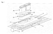
- Fig. 1
- eine perspektivische Explosionsansicht eines Teils einer erfindungsgemäßen Ablaufvorrichtung;
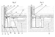
- Fig. 2
- einen Querschnitt durch eine erfindungsgemäße Ablaufvorrichtung im eingebauten Zustand mit einem Aufnahmerahmen in einer ersten Stellung;
- Fig. 2a
- eine Detailvergrößerung der
Fig. 2 ; - Fig. 3
- eine
Fig. 2 entsprechende Ansicht auf die Ablaufvorrichtung mit dem Aufnahmerahmen in einer zweiten Stellung; - Fig. 3a
- eine Detailvergrößerung der
Fig. 3 ; - Fig. 4
- einen vergrößerten perspektivischen Schnitt durch die Vorrichtung gemäß
Fig. 2 mit dem Aufnahmerahmen in der ersten Stellung; - Fig. 5
- eine schematische Draufsicht auf die Ablaufvorrichtung gemäß
Fig. 2 ; - Fig. 6
- eine Untenansicht zweier unterschiedlicher Aufnahmerahmen für eine erfindungsgemäße Ablaufvorrichtung;
- Fig. 7
- eine Draufsicht auf die beiden unterschiedlichen Aufnahmerahmen gemäß
Fig. 6 ;
- Fig. 8
- einen Schnitt gemäß den Pfeilen VIII-VIII in
Fig. 7 - Fig. 9
- eine perspektivische Ansicht einer erfindungsgemäßen Ablaufvorrichtung mit einer erfindungsgemäßen Ablaufrinne im eingebauten Zustand;
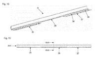
- Fig. 10
- eine perspektivische Ansicht einer erfindungsgemäßen Ablaufrinne;
- Fig. 11
- einen Querschnitt durch einen ersten Abschnitt einer erfindungsgemäßen Ablaufvorrichtung mit einer erfindungsgemäßen Ablaufrinne im eingebauten Zustand;
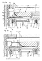
- Fig. 12
- eine Detailvergrößerung gemäß dem Pfeil XII in
Fig. 11 ; - Fig. 13
- einen Querschnitt durch einen zweiten Abschnitt einer erfindungsgemäßen Ablaufvorrichtung mit einer erfindungsgemäßen Ablaufrinne im eingebauten Zustand;
- Fig. 14
- eine Detailvergrößerung gemäß dem Pfeil XIV in
Fig. 13 ; - Fig. 15
- eine Seitenansicht einer erfindungsgemäßen Ablaufrinne;
- Fig. 16
- eine Seitenansicht einer erfindungsgemäßen Ablaufrinne gemäß dem Pfeil XVI in
Fig. 15 ; - Fig. 17
- einen Schnitt gemäß den Pfeilen XVII - XVII in
Fig. 15 .
- Fig. 1
- an exploded perspective view of a portion of a drain device according to the invention;
- Fig. 2
- a cross section through a drain device according to the invention in the installed state with a receiving frame in a first position;
- Fig. 2a
- an enlarged detail of the
Fig. 2 ; - Fig. 3
- a
Fig. 2 corresponding view of the drain device with the receiving frame in a second position; - Fig. 3a
- an enlarged detail of the
Fig. 3 ; - Fig. 4
- an enlarged perspective section through the device according to
Fig. 2 with the frame in the first position; - Fig. 5
- a schematic plan view of the drain device according to
Fig. 2 ; - Fig. 6
- a bottom view of two different receiving frame for a drain device according to the invention;
- Fig. 7
- a plan view of the two different receiving frame according to
Fig. 6 ;
- Fig. 8
- a section according to the arrows VIII-VIII in
Fig. 7 - Fig. 9
- a perspective view of a drain device according to the invention with a gutter according to the invention in the installed state;
- Fig. 10
- a perspective view of a gutter according to the invention;
- Fig. 11
- a cross section through a first portion of a drain device according to the invention with a drainage channel according to the invention in the installed state;
- Fig. 12
- an enlarged detail according to the arrow XII in
Fig. 11 ; - Fig. 13
- a cross section through a second portion of a drain device according to the invention with a gutter according to the invention in the installed state;
- Fig. 14
- an enlarged detail according to the arrow XIV in
Fig. 13 ; - Fig. 15
- a side view of a gutter according to the invention;
- Fig. 16
- a side view of a gutter according to the invention according to the arrow XVI in
Fig. 15 ; - Fig. 17
- a section according to the arrows XVII - XVII in
Fig. 15 ,
In den Figuren sind gleiche oder funktional gleiche Teile mit gleichen Bezugszeichen versehen.In the figures, identical or functionally identical parts are provided with the same reference numerals.
Die aus
Das Aufnahmeteil 4 ist mit dem Ablaufgehäuse 1 fest verbunden, beispielsweise verklebt. Es besteht durchaus die Möglichkeit, dass das Ablaufgehäuse 1 und das Aufnahmeteil 4 einstückig ausgebildet sind, so dass das Aufnahmeteil 4 als Teil des Ablaufgehäuses 1 ausgeführt ist. In diesem Fall kann das Ablaufgehäuse 1 beispielsweise eine die Wassereinlauföffnung 3 umgebende Auflageschulter auf weisen.The receiving
Im in abgebildeten Ausführungsbeispiel ist das obere Ende des Ablaufgehäuses 1 und des Aufnahmeteiles 4 von einem Einlaufkragen 5 umgeben (siehe
Es besteht durchaus die Möglichkeit, bei einer erfindungsgemäßen Ablaufvorrichtung die Gitter 7 und/oder den Einlaufkragen 5 wegzulassen.It is quite possible to omit the
Die Ablaufvorrichtung umfasst weiterhin eine erfindungsgemäße Ablaufrinne 9, durch die das Wasser in die Wassereinlauföffnung 3 gelangen kann. Die Ablaufrinne 9 ist im Bereich der Wassereinlauföffnung 3 nach oben und zur von der Wand abgewandten Seite geöffnet (siehe
Die Ablaufrinne 9 ist außerhalb des Bereichs der Wassereinlauföffnung 3 anders gestaltet. Dort weist sie auf der dem vertikalen Schenkel 9a gegenüberliegenden Seite eine sich von dem Rinnenboden 9b vierteilkreisförmig nach oben erstreckende Seitenwand 9c und einen sich unter die Bodenfliesen 20 erstreckenden horizontalen Verbindungsabschnitt 9d auf (siehe
Die Ablaufrinne 9 ist im abgebildeten Ausführungsbeispiel in den Wandaufbau 10 integriert. Dabei umfasst der Wandaufbau im abgebildeten Ausführungsbeispiel von links nach rechts in
Die Ablaufrinne 9 liegt mit ihrer in
Neben der Ablaufrinne 9 ist eine Abdeckung 19 angeordnet, deren Oberseite sich im abgebildeten Ausführungsbeispiel auf der gleichen Höhe wie die Oberseite der Bodenfliesen 20 befindet. Dementsprechend kann das abzuführende Wasser von den Bodenfliesen 20 über die Abdeckung 19 durch die Abflussöffnung 18 in die Ablaufrinne 9 gelangen. Dabei fluchtet die in den
Die der Wand zugewandte beziehungsweise die in
Im abgebildeten Ausführungsbeispiel wird die Abdeckung 19 durch einen umlaufenden Rahmen 21 gebildet, in den ein Einlegeteil 22 eingebracht werden kann. Dabei kann das Einlegeteil 22 aus dem gleichen Material wie die Bodenfliesen bestehen. Es kann aber auch vorgesehen sein, die Abdeckung anders zugestalten, beispielsweise als einstückiges Teil aus Metall.In the illustrated embodiment, the
Die Ablaufvorrichtung umfasst weiterhin einen mit einer Öffnung 23 versehenen Aufnahmerahmen 24, der im eingebauten Zustand in eine Aussparung des Aufnahmeteiles 4 eingesetzt ist. Der Aufnahmerahmen weist einen oberen, umlaufenden Kragen 25 und eine sich von diesem im eingebauten Zustand nach unten erstreckende umlaufende Fläche 26 auf (siehe
Im abgebildeten Ausführungsbeispiel ist auf der Innenseite des Aufnahmeteils 4 eine umlaufende Dichtung 27 angeordnet, die den Aufnahmerahmen 24 gegen das Aufnahmeteil 4 abdichtet. Die Dichtung 27 kann als feste oder lose Dichtung ausgebildet sein.In the illustrated embodiment, a
Alternativ dazu kann der Aufnahmerahmen 24 eine umlaufende, nicht abgebildete Dichtung aufweisen. Diese könnte an der Unterseite des Kragens 25 oder an der Außenseite der Fläche 26 angeordnet sein. Alternativ dazu kann der Aufnahmerahmen 24 in das Aufnahmeteil 4 eingeklebt werden. Dazu kann Kleber auf die Unterseite des umlaufenden Kragens 25 und/ oder umlaufend auf die vertikale Fläche 26 aufgetragen werden.Alternatively, the receiving
Die Ablaufvorrichtung umfasst weiterhin einen Geruchsverschluss 28, der mit seinem oberen Rand im eingebauten Zustand in der Öffnung 23 des Aufnahmerahmens 24 gehalten wird, wobei die übrigen Abschnitte des Geruchsverschlusses 28 durch den Aufnahmerahmen 24 nach unten hindurchragen. Zur Halterung des Geruchsverschlusses 28 weist der Aufnahmerahmen 24 in die Öffnung 23 hineinragende, stirnseitiges umlaufende Schultern 32 und einen mittig querverlaufenden Steg 33 auf (siehe
Die Öffnung 23 des Aufnahmerahmen 24 ist länglich oval und von seitlichen Längsabschnitten 29, 30 begrenzt (siehe beispielsweise
Aufgrund dieser Gestaltung kann durch Drehung des Aufnahmerahmens 24 um 180° um die vertikale Richtung der Abstand der Öffnung 23 zur Wand verändert werden.
Insbesondere ist der Abstand a1 zwischen der wandseitigen Begrenzung der Öffnung 23 beziehungsweise dem in der Öffnung 23 befindlichen Geruchsverschluss 28 und dem Entkopplungsstreifen 13, der auf dieser Höhe die äußere Begrenzung der Wand darstellt, kleiner als der Abstand a2 in der zweiten Stellung. Bei der in
In der Einbausituation gemäß
Der in
Durch die Verwendung unterschiedlicher Aufnahmerahmen 24, 24' wird dem Benutzer also die Möglichkeit eröffnet, den Abstand a1, a2 der Öffnung 23, 23' beziehungsweise des Geruchsverschlusses 28 von der Wand noch besser an die lokalen Gegebenheiten anzupassen.By using different receiving frames 24, 24 ', the user is thus given the opportunity to better adapt the distance a 1 , a 2 of the
Der Einbau einer erfindungsgemäßen Ablaufvorrichtung erfolgt dadurch, dass in einem ersten Verfahrensschritt das Ablaufgehäuse 1 vor dem Aufbringen des Estrichs auf dem Rohboden montiert und mit einem Abflussrohr verbunden wird. Anschließend wird der Estrich auf den Rohboden aufgebracht, so dass der Einlaufkragen und die Gitter zumindest teilweise von dem Estrich umgeben sind. Anschließend werden der gesamte Boden- und Wandbereich einschließlich der bereits montierten Ablaufteile eingedichtet.The installation of a drainage device according to the invention takes place in that in a first method step, the
Die Ablaufrinne 9 wird angrenzend an die verputzte Wand, insbesondere zusammen mit Dichtstreifen 14, montiert. Daran anschließend werden die Wandfliesen 16 aufgebracht, wodurch der vertikale Schenkel 9a der Ablaufrinne 9 gegebenenfalls abgedeckt werden kann.The
Der Aufnahmerahmen 24 wird so eingesetzt, dass das wandseitige Ende des in den Aufnahmerahmen 24 einzusetzenden Geruchsverschlusses 28 in horizontaler Richtung einen ausreichenden Abstand b1, b2 von der Außenseite der Wandfliese 16 aufweist, so dass er noch nach oben entnehmbar ist. Alternativ wird aus einer Mehrzahl von Aufnahmerahmen 24, 24' ein passender Aufnahmerahmen 24, 24' ausgesucht, der in der geeigneten Stellung die Entnehmbarkeit des Geruchsverschlusses 28 gewährleistet.The receiving
Anschließend wird der Aufnahmerahmen 24, 24' in dem Aufnahmeteil 4 oder der Oberseite des Auflaufgehäuses 1 verklebt oder über Dichtungen 27 befestigt. Der Geruchsverschluss 28 wird eingesetzt und auf die Oberseite des Geruchsverschlusses 28 wird die Abdeckung 19 lose aufgelegt. Anschließend können die Bodenfliesen 20 passend an die Abdeckung 19 angearbeitet werden.Subsequently, the receiving
Durch diese Gestaltung wird gewährleistet, dass der Geruchsverschluss 28 trotz des sehr wandnahen Einbaus der Ablaufvorrichtung jederzeit nach Abnahme der Abdeckung 19 entnommen und gereinigt werden kann.This design ensures that the
Im mittleren Abschnitt 36 weist die Ablaufrinne 9 einen im Wesentlichen L-förmigen Querschnitt auf, mit dem im eingebauten Zustand vertikalen Schenkel 9a, der in den Wandaufbau 10 nach oben hinein ragt oder unter der untersten Wandfliese 16 endet, und einem als Rinnenboden 9b dienenden horizontalen Schenkel. In dem mittleren Abschnitt 36 kann also das Wasser direkt horizontal zur Seite aus der Ablaufrinne 9 austreten, weil in dem mittleren Bereich 36 keine dem vertikalen Schenkel 9a gegenüberliegende Seitenwand 9c vorgesehen ist.In the
In dem mittleren Bereich 36 ist somit die in den beiden äußeren Abschnitten 35, 37 vorgesehene, von dem sich viertelkreisförmig nach oben erstreckenden Abschnitt gebildete Seitenwand 9c ausgeschnitten oder weggelassen (siehe
Der in den äußeren Abschnitten 35, 37 vorgesehene Verbindungsabschnitt 9d weist Öffnungen 38 auf, durch die Fliesenkleber hindurchtreten kann, um die Ablaufrinne 9 auf der Oberseite des Estrichs beziehungsweise darauf angeordneter Dichtschichten zu befestigen.The connecting
Der Rinnenboden 9b weist in den beiden äußeren Abschnitten 35, 37 ein Gefälle in Längsrichtung zum mittleren Abschnitt 36 hin auf.The
Die Gestaltung der Ablaufrinne 9 aus den beiden beschriebenen Teilen 39, 40 bietet fertigungstechnische Vorteile, weil die beiden Teile 39, 40 getrennt voneinander gefertigt und vergleichsweise einfach zu der Ablaufrinne 9 zusammengefügt werden können.The design of the
Die
Das Wasser läuft von den äußeren Abschnitten 35, 37 wegen des Gefälles des Rinnenbodens 9b über diesen in den mittleren Abschnitt 36 der Ablaufrinne 9. Dieser mittlere Abschnitt 36 der Ablaufrinne 9 und der dazu gehörige Bereich der Ablaufvorrichtung sind in
Die Ablaufrinne 9 ist gemäß den
Die Ablaufrinne 9 ist gemäß den
Es besteht die Möglichkeit, für die Ablaufrinne 9 in dem Estrich 8 eine vorzugsweise flache Vertiefung vorzusehen, in die die Ablaufrinne 9 gegebenenfalls nach Eindichtung des Bereichs zumindest abschnittsweise eingebracht werden kann.It is possible to provide a preferably shallow recess for the
Claims (15)
dadurch gekennzeichnet dass die Ablaufrinne (9) eine Ablaufrinne (9) nach einem der Ansprüche 1 bis 10 ist.
characterized in that the gutter (9) is a gutter (9) according to one of claims 1 to 10.
Priority Applications (3)
| Application Number | Priority Date | Filing Date | Title |
|---|---|---|---|
| SI201331747T SI2765250T1 (en) | 2013-02-07 | 2013-03-11 | Drainage channel |
| PL13158630T PL2765250T3 (en) | 2013-02-07 | 2013-03-11 | Drainage channel |
| DE202014100552.8U DE202014100552U1 (en) | 2013-02-07 | 2014-02-07 | draining device |
Applications Claiming Priority (1)
| Application Number | Priority Date | Filing Date | Title |
|---|---|---|---|
| DE102013101207.8A DE102013101207A1 (en) | 2013-02-07 | 2013-02-07 | draining device |
Publications (2)
| Publication Number | Publication Date |
|---|---|
| EP2765250A1 true EP2765250A1 (en) | 2014-08-13 |
| EP2765250B1 EP2765250B1 (en) | 2020-06-10 |
Family
ID=47844201
Family Applications (1)
| Application Number | Title | Priority Date | Filing Date |
|---|---|---|---|
| EP13158630.7A Active EP2765250B1 (en) | 2013-02-07 | 2013-03-11 | Drainage channel |
Country Status (8)
| Country | Link |
|---|---|
| EP (1) | EP2765250B1 (en) |
| DE (1) | DE102013101207A1 (en) |
| DK (1) | DK2765250T3 (en) |
| ES (1) | ES2804264T3 (en) |
| HU (1) | HUE049676T2 (en) |
| PL (1) | PL2765250T3 (en) |
| PT (1) | PT2765250T (en) |
| SI (1) | SI2765250T1 (en) |
Cited By (2)
| Publication number | Priority date | Publication date | Assignee | Title |
|---|---|---|---|---|
| FR3026420A1 (en) * | 2014-09-30 | 2016-04-01 | Fr D Assainissement Sfa Soc | CANIVEAU AND SHOWER RECEIVER |
| DE102015109211A1 (en) | 2015-06-10 | 2016-12-15 | Dallmer Gmbh & Co. Kg | gutter |
Families Citing this family (2)
| Publication number | Priority date | Publication date | Assignee | Title |
|---|---|---|---|---|
| DE102014013135A1 (en) | 2014-09-10 | 2016-03-10 | Viega Gmbh & Co. Kg | Wall drainage channel for a shower |
| DE102015104598A1 (en) | 2015-03-26 | 2016-09-29 | Dallmer Gmbh & Co. Kg | Drain device, drain arrangement and method for producing a drain assembly |
Citations (3)
| Publication number | Priority date | Publication date | Assignee | Title |
|---|---|---|---|---|
| US6014780A (en) * | 1998-05-04 | 2000-01-18 | Eagle Natural Stone | Shower bath and drain |
| WO2005111327A1 (en) * | 2004-05-13 | 2005-11-24 | Aachen Industries Pty Ltd | Slot-drain assembly |
| DE202005019964U1 (en) * | 2005-12-21 | 2006-03-02 | Kessel Gmbh | drainage system |
Family Cites Families (4)
| Publication number | Priority date | Publication date | Assignee | Title |
|---|---|---|---|---|
| DE9419373U1 (en) * | 1994-12-05 | 1995-03-16 | Wilhelm Hafner Gmbh | Gutter for laying in a floor |
| ATE283398T1 (en) * | 1997-07-23 | 2004-12-15 | Bluecher Germany Gmbh | BUILT-IN CHANNEL FOR LAYING IN A FLOOR |
| DE202010017610U1 (en) * | 2010-06-16 | 2012-03-14 | Buchberger Gmbh Profilsysteme | gutter |
| NL2005949C2 (en) * | 2011-01-04 | 2012-07-05 | Easy Sanitairy Solutions Bv | DRAIN WITH UNIDIRECTIONAL DRAINAGE. |
-
2013
- 2013-02-07 DE DE102013101207.8A patent/DE102013101207A1/en active Pending
- 2013-03-11 DK DK13158630.7T patent/DK2765250T3/en active
- 2013-03-11 PT PT131586307T patent/PT2765250T/en unknown
- 2013-03-11 EP EP13158630.7A patent/EP2765250B1/en active Active
- 2013-03-11 PL PL13158630T patent/PL2765250T3/en unknown
- 2013-03-11 ES ES13158630T patent/ES2804264T3/en active Active
- 2013-03-11 SI SI201331747T patent/SI2765250T1/en unknown
- 2013-03-11 HU HUE13158630A patent/HUE049676T2/en unknown
Patent Citations (3)
| Publication number | Priority date | Publication date | Assignee | Title |
|---|---|---|---|---|
| US6014780A (en) * | 1998-05-04 | 2000-01-18 | Eagle Natural Stone | Shower bath and drain |
| WO2005111327A1 (en) * | 2004-05-13 | 2005-11-24 | Aachen Industries Pty Ltd | Slot-drain assembly |
| DE202005019964U1 (en) * | 2005-12-21 | 2006-03-02 | Kessel Gmbh | drainage system |
Cited By (2)
| Publication number | Priority date | Publication date | Assignee | Title |
|---|---|---|---|---|
| FR3026420A1 (en) * | 2014-09-30 | 2016-04-01 | Fr D Assainissement Sfa Soc | CANIVEAU AND SHOWER RECEIVER |
| DE102015109211A1 (en) | 2015-06-10 | 2016-12-15 | Dallmer Gmbh & Co. Kg | gutter |
Also Published As
| Publication number | Publication date |
|---|---|
| PL2765250T3 (en) | 2020-11-16 |
| EP2765250B1 (en) | 2020-06-10 |
| DE102013101207A1 (en) | 2014-08-21 |
| DK2765250T3 (en) | 2020-07-13 |
| SI2765250T1 (en) | 2020-09-30 |
| PT2765250T (en) | 2020-07-13 |
| HUE049676T2 (en) | 2020-10-28 |
| ES2804264T3 (en) | 2021-02-05 |
Similar Documents
| Publication | Publication Date | Title |
|---|---|---|
| EP2315544B1 (en) | Foam shower base element | |
| EP2085006B1 (en) | Shower floor element | |
| EP2664722B1 (en) | Floor drain with a cover for receiving a tile | |
| DE202015105638U1 (en) | floor drain | |
| DE202014007357U1 (en) | Floor drain with sealing mat | |
| EP3705655A1 (en) | Floor drain for removing water from a walkable floor into a sewer pipe | |
| EP2765250B1 (en) | Drainage channel | |
| EP2227997A1 (en) | Hardfoam shower base element | |
| DE202014100552U1 (en) | draining device | |
| EP2278081B1 (en) | Connection frame for a floor drain and floor drain | |
| EP2634321B1 (en) | Floor drain | |
| EP3293317B1 (en) | Draining device for draining water | |
| DE102012106924A1 (en) | Shower drain assembly installed in bathroom, has end portion which is used to place and apply tiles, and is displaceable relative to mounting portion | |
| DE202014007391U1 (en) | Floor drain with inlet funnel | |
| EP3388577A1 (en) | System for dewatering | |
| EP3375944B1 (en) | Drainage channel, method of manufacture and method of installation | |
| EP2759646B1 (en) | Device for floor drain in the proximity of a wall | |
| DE202011004001U1 (en) | drain arrangement | |
| DE202014007356U1 (en) | Water drain with insert | |
| EP2995730B1 (en) | Floor drain with inlet funnel | |
| DE102013101208B4 (en) | Drainage device for placement in a floor adjacent to a wall | |
| DE102013022337B3 (en) | Drainage device | |
| DE202018106974U1 (en) | drainage channel | |
| DE102005061677A1 (en) | End profile for the edge termination of balconies or terraces o. The like. With a drainage layer | |
| DE10201346B4 (en) | Drainage device for a tiled floor |
Legal Events
| Date | Code | Title | Description |
|---|---|---|---|
| PUAI | Public reference made under article 153(3) epc to a published international application that has entered the european phase |
Free format text: ORIGINAL CODE: 0009012 |
|
| 17P | Request for examination filed |
Effective date: 20140409 |
|
| AK | Designated contracting states |
Kind code of ref document: A1 Designated state(s): AL AT BE BG CH CY CZ DE DK EE ES FI FR GB GR HR HU IE IS IT LI LT LU LV MC MK MT NL NO PL PT RO RS SE SI SK SM TR |
|
| AX | Request for extension of the european patent |
Extension state: BA ME |
|
| RBV | Designated contracting states (corrected) |
Designated state(s): AL AT BE BG CH CY CZ DE DK EE ES FI FR GB GR HR HU IE IS IT LI LT LU LV MC MK MT NL NO PL PT RO RS SE SI SK SM TR |
|
| APBK | Appeal reference recorded |
Free format text: ORIGINAL CODE: EPIDOSNREFNE |
|
| APBN | Date of receipt of notice of appeal recorded |
Free format text: ORIGINAL CODE: EPIDOSNNOA2E |
|
| APBR | Date of receipt of statement of grounds of appeal recorded |
Free format text: ORIGINAL CODE: EPIDOSNNOA3E |
|
| APAF | Appeal reference modified |
Free format text: ORIGINAL CODE: EPIDOSCREFNE |
|
| APBT | Appeal procedure closed |
Free format text: ORIGINAL CODE: EPIDOSNNOA9E |
|
| STAA | Information on the status of an ep patent application or granted ep patent |
Free format text: STATUS: EXAMINATION IS IN PROGRESS |
|
| GRAP | Despatch of communication of intention to grant a patent |
Free format text: ORIGINAL CODE: EPIDOSNIGR1 |
|
| STAA | Information on the status of an ep patent application or granted ep patent |
Free format text: STATUS: GRANT OF PATENT IS INTENDED |
|
| INTG | Intention to grant announced |
Effective date: 20200212 |
|
| GRAS | Grant fee paid |
Free format text: ORIGINAL CODE: EPIDOSNIGR3 |
|
| GRAA | (expected) grant |
Free format text: ORIGINAL CODE: 0009210 |
|
| STAA | Information on the status of an ep patent application or granted ep patent |
Free format text: STATUS: THE PATENT HAS BEEN GRANTED |
|
| AK | Designated contracting states |
Kind code of ref document: B1 Designated state(s): AL AT BE BG CH CY CZ DE DK EE ES FI FR GB GR HR HU IE IS IT LI LT LU LV MC MK MT NL NO PL PT RO RS SE SI SK SM TR |
|
| REG | Reference to a national code |
Ref country code: GB Ref legal event code: FG4D Free format text: NOT ENGLISH |
|
| REG | Reference to a national code |
Ref country code: AT Ref legal event code: REF Ref document number: 1279311 Country of ref document: AT Kind code of ref document: T Effective date: 20200615 Ref country code: CH Ref legal event code: EP |
|
| REG | Reference to a national code |
Ref country code: DE Ref legal event code: R096 Ref document number: 502013014778 Country of ref document: DE |
|
| REG | Reference to a national code |
Ref country code: IE Ref legal event code: FG4D Free format text: LANGUAGE OF EP DOCUMENT: GERMAN |
|
| REG | Reference to a national code |
Ref country code: DK Ref legal event code: T3 Effective date: 20200709 Ref country code: PT Ref legal event code: SC4A Ref document number: 2765250 Country of ref document: PT Date of ref document: 20200713 Kind code of ref document: T Free format text: AVAILABILITY OF NATIONAL TRANSLATION Effective date: 20200706 |
|
| REG | Reference to a national code |
Ref country code: NL Ref legal event code: FP |
|
| REG | Reference to a national code |
Ref country code: SE Ref legal event code: TRGR |
|
| REG | Reference to a national code |
Ref country code: NO Ref legal event code: T2 Effective date: 20200610 |
|
| REG | Reference to a national code |
Ref country code: SK Ref legal event code: T3 Ref document number: E 34792 Country of ref document: SK |
|
| REG | Reference to a national code |
Ref country code: LT Ref legal event code: MG4D |
|
| REG | Reference to a national code |
Ref country code: HU Ref legal event code: AG4A Ref document number: E049676 Country of ref document: HU |
|
| PG25 | Lapsed in a contracting state [announced via postgrant information from national office to epo] |
Ref country code: FI Free format text: LAPSE BECAUSE OF FAILURE TO SUBMIT A TRANSLATION OF THE DESCRIPTION OR TO PAY THE FEE WITHIN THE PRESCRIBED TIME-LIMIT Effective date: 20200610 Ref country code: LT Free format text: LAPSE BECAUSE OF FAILURE TO SUBMIT A TRANSLATION OF THE DESCRIPTION OR TO PAY THE FEE WITHIN THE PRESCRIBED TIME-LIMIT Effective date: 20200610 Ref country code: GR Free format text: LAPSE BECAUSE OF FAILURE TO SUBMIT A TRANSLATION OF THE DESCRIPTION OR TO PAY THE FEE WITHIN THE PRESCRIBED TIME-LIMIT Effective date: 20200911 |
|
| PG25 | Lapsed in a contracting state [announced via postgrant information from national office to epo] |
Ref country code: BG Free format text: LAPSE BECAUSE OF FAILURE TO SUBMIT A TRANSLATION OF THE DESCRIPTION OR TO PAY THE FEE WITHIN THE PRESCRIBED TIME-LIMIT Effective date: 20200910 Ref country code: RS Free format text: LAPSE BECAUSE OF FAILURE TO SUBMIT A TRANSLATION OF THE DESCRIPTION OR TO PAY THE FEE WITHIN THE PRESCRIBED TIME-LIMIT Effective date: 20200610 Ref country code: HR Free format text: LAPSE BECAUSE OF FAILURE TO SUBMIT A TRANSLATION OF THE DESCRIPTION OR TO PAY THE FEE WITHIN THE PRESCRIBED TIME-LIMIT Effective date: 20200610 Ref country code: LV Free format text: LAPSE BECAUSE OF FAILURE TO SUBMIT A TRANSLATION OF THE DESCRIPTION OR TO PAY THE FEE WITHIN THE PRESCRIBED TIME-LIMIT Effective date: 20200610 |
|
| PG25 | Lapsed in a contracting state [announced via postgrant information from national office to epo] |
Ref country code: AL Free format text: LAPSE BECAUSE OF FAILURE TO SUBMIT A TRANSLATION OF THE DESCRIPTION OR TO PAY THE FEE WITHIN THE PRESCRIBED TIME-LIMIT Effective date: 20200610 |
|
| PG25 | Lapsed in a contracting state [announced via postgrant information from national office to epo] |
Ref country code: EE Free format text: LAPSE BECAUSE OF FAILURE TO SUBMIT A TRANSLATION OF THE DESCRIPTION OR TO PAY THE FEE WITHIN THE PRESCRIBED TIME-LIMIT Effective date: 20200610 Ref country code: RO Free format text: LAPSE BECAUSE OF FAILURE TO SUBMIT A TRANSLATION OF THE DESCRIPTION OR TO PAY THE FEE WITHIN THE PRESCRIBED TIME-LIMIT Effective date: 20200610 Ref country code: SM Free format text: LAPSE BECAUSE OF FAILURE TO SUBMIT A TRANSLATION OF THE DESCRIPTION OR TO PAY THE FEE WITHIN THE PRESCRIBED TIME-LIMIT Effective date: 20200610 |
|
| REG | Reference to a national code |
Ref country code: ES Ref legal event code: FG2A Ref document number: 2804264 Country of ref document: ES Kind code of ref document: T3 Effective date: 20210205 |
|
| PG25 | Lapsed in a contracting state [announced via postgrant information from national office to epo] |
Ref country code: IS Free format text: LAPSE BECAUSE OF FAILURE TO SUBMIT A TRANSLATION OF THE DESCRIPTION OR TO PAY THE FEE WITHIN THE PRESCRIBED TIME-LIMIT Effective date: 20201010 |
|
| REG | Reference to a national code |
Ref country code: DE Ref legal event code: R097 Ref document number: 502013014778 Country of ref document: DE |
|
| PLBE | No opposition filed within time limit |
Free format text: ORIGINAL CODE: 0009261 |
|
| STAA | Information on the status of an ep patent application or granted ep patent |
Free format text: STATUS: NO OPPOSITION FILED WITHIN TIME LIMIT |
|
| PGFP | Annual fee paid to national office [announced via postgrant information from national office to epo] |
Ref country code: MC Payment date: 20210323 Year of fee payment: 9 Ref country code: LU Payment date: 20210319 Year of fee payment: 9 |
|
| 26N | No opposition filed |
Effective date: 20210311 |
|
| PG25 | Lapsed in a contracting state [announced via postgrant information from national office to epo] |
Ref country code: HU Free format text: LAPSE BECAUSE OF NON-PAYMENT OF DUE FEES Effective date: 20210312 |
|
| PGFP | Annual fee paid to national office [announced via postgrant information from national office to epo] |
Ref country code: IE Payment date: 20220322 Year of fee payment: 10 Ref country code: DK Payment date: 20220323 Year of fee payment: 10 |
|
| PGFP | Annual fee paid to national office [announced via postgrant information from national office to epo] |
Ref country code: PT Payment date: 20220303 Year of fee payment: 10 |
|
| PGFP | Annual fee paid to national office [announced via postgrant information from national office to epo] |
Ref country code: SI Payment date: 20220309 Year of fee payment: 10 |
|
| PG25 | Lapsed in a contracting state [announced via postgrant information from national office to epo] |
Ref country code: MC Free format text: LAPSE BECAUSE OF NON-PAYMENT OF DUE FEES Effective date: 20220331 |
|
| PG25 | Lapsed in a contracting state [announced via postgrant information from national office to epo] |
Ref country code: LU Free format text: LAPSE BECAUSE OF NON-PAYMENT OF DUE FEES Effective date: 20220311 |
|
| PGFP | Annual fee paid to national office [announced via postgrant information from national office to epo] |
Ref country code: NO Payment date: 20230324 Year of fee payment: 11 Ref country code: FR Payment date: 20230324 Year of fee payment: 11 Ref country code: CZ Payment date: 20230303 Year of fee payment: 11 Ref country code: AT Payment date: 20230322 Year of fee payment: 11 |
|
| PGFP | Annual fee paid to national office [announced via postgrant information from national office to epo] |
Ref country code: TR Payment date: 20230309 Year of fee payment: 11 Ref country code: SK Payment date: 20230307 Year of fee payment: 11 Ref country code: SE Payment date: 20230314 Year of fee payment: 11 Ref country code: PL Payment date: 20230303 Year of fee payment: 11 Ref country code: IT Payment date: 20230322 Year of fee payment: 11 Ref country code: GB Payment date: 20230322 Year of fee payment: 11 Ref country code: DE Payment date: 20230331 Year of fee payment: 11 Ref country code: BE Payment date: 20230321 Year of fee payment: 11 |
|
| PG25 | Lapsed in a contracting state [announced via postgrant information from national office to epo] |
Ref country code: CY Free format text: LAPSE BECAUSE OF FAILURE TO SUBMIT A TRANSLATION OF THE DESCRIPTION OR TO PAY THE FEE WITHIN THE PRESCRIBED TIME-LIMIT Effective date: 20200610 |
|
| PGFP | Annual fee paid to national office [announced via postgrant information from national office to epo] |
Ref country code: NL Payment date: 20230321 Year of fee payment: 11 |
|
| P01 | Opt-out of the competence of the unified patent court (upc) registered |
Effective date: 20230616 |
|
| PGFP | Annual fee paid to national office [announced via postgrant information from national office to epo] |
Ref country code: ES Payment date: 20230529 Year of fee payment: 11 Ref country code: CH Payment date: 20230401 Year of fee payment: 11 |
|
| PG25 | Lapsed in a contracting state [announced via postgrant information from national office to epo] |
Ref country code: PT Free format text: LAPSE BECAUSE OF NON-PAYMENT OF DUE FEES Effective date: 20230911 |
|
| REG | Reference to a national code |
Ref country code: DK Ref legal event code: EBP Effective date: 20230331 |
|
| REG | Reference to a national code |
Ref country code: SI Ref legal event code: KO00 Effective date: 20231122 |
|
| REG | Reference to a national code |
Ref country code: IE Ref legal event code: MM4A |
|
| PG25 | Lapsed in a contracting state [announced via postgrant information from national office to epo] |
Ref country code: SI Free format text: LAPSE BECAUSE OF NON-PAYMENT OF DUE FEES Effective date: 20230312 Ref country code: IE Free format text: LAPSE BECAUSE OF NON-PAYMENT OF DUE FEES Effective date: 20230311 |
|
| PGFP | Annual fee paid to national office [announced via postgrant information from national office to epo] |
Ref country code: NL Payment date: 20240320 Year of fee payment: 12 |