EP2765250A1 - Rigole d'écoulement - Google Patents
Rigole d'écoulement Download PDFInfo
- Publication number
- EP2765250A1 EP2765250A1 EP13158630.7A EP13158630A EP2765250A1 EP 2765250 A1 EP2765250 A1 EP 2765250A1 EP 13158630 A EP13158630 A EP 13158630A EP 2765250 A1 EP2765250 A1 EP 2765250A1
- Authority
- EP
- European Patent Office
- Prior art keywords
- gutter
- wall
- drainage
- channel
- floor
- Prior art date
- Legal status (The legal status is an assumption and is not a legal conclusion. Google has not performed a legal analysis and makes no representation as to the accuracy of the status listed.)
- Granted
Links
- XLYOFNOQVPJJNP-UHFFFAOYSA-N water Substances O XLYOFNOQVPJJNP-UHFFFAOYSA-N 0.000 claims description 40
- 238000007789 sealing Methods 0.000 claims description 11
- 239000000853 adhesive Substances 0.000 claims description 5
- 230000001070 adhesive effect Effects 0.000 claims description 5
- 239000000565 sealant Substances 0.000 claims description 5
- 230000037431 insertion Effects 0.000 abstract 1
- 238000003780 insertion Methods 0.000 abstract 1
- 238000009434 installation Methods 0.000 description 7
- 239000002131 composite material Substances 0.000 description 3
- 230000002093 peripheral effect Effects 0.000 description 2
- 239000011505 plaster Substances 0.000 description 2
- 238000010276 construction Methods 0.000 description 1
- 238000004519 manufacturing process Methods 0.000 description 1
- 239000000463 material Substances 0.000 description 1
- 239000002184 metal Substances 0.000 description 1
- 238000000034 method Methods 0.000 description 1
- 239000007787 solid Substances 0.000 description 1
- 230000000007 visual effect Effects 0.000 description 1
Images


Classifications
-
- E—FIXED CONSTRUCTIONS
- E03—WATER SUPPLY; SEWERAGE
- E03F—SEWERS; CESSPOOLS
- E03F5/00—Sewerage structures
- E03F5/04—Gullies inlets, road sinks, floor drains with or without odour seals or sediment traps
- E03F5/0407—Floor drains for indoor use
- E03F5/0408—Floor drains for indoor use specially adapted for showers
Definitions
- the present invention relates to a drainage channel according to the preamble of claim 1, a drainage device having such a drainage channel and an arrangement of such a drainage device adjacent to a wall at least partially in a floor of a room.
- Drainage devices which have a drain opening in the region of the lower edge of the wall, are also called wall drains. Such wall drains are usually completely or partially integrated into the wall. The positioning of a drainage device in the ground in front of the wall while maintaining a wall-side drain opening is still rare because of technical challenges currently.
- the problem underlying the present invention is to provide a gutter and a drainage device of the type mentioned, which ensure a low installation cost and / or an attractive appearance. Furthermore, an initially mentioned arrangement of the drainage device is to be indicated adjacent to a wall at least partially in a floor of a room.
- the height of the vertical leg from its upper end to the bottom of the channel bottom is less than 5 cm, in particular less than 3 cm and / or that the depth of the gutter from the wall-side end of the vertical leg to the room side End of the gutter bottom is less than 5 cm, in particular less than 3 cm.
- the gutter may at least partially have a side wall, which adjoins room side of the channel bottom, wherein the depth of the gutter from the wall-side end of the vertical leg to the room-side end of the side wall is less than 5 cm, in particular less than 3 cm. Due to this configuration, the gutter can be placed in the space below the bottom wall tile and / or wall side of the floor tiles. In particular, the gutter both a height, and a depth corresponding to the usual tile thicknesses in the sanitary area. This results in a visually appealing impression of the drainage device provided with such a drainage channel.
- the gutter is suitable to be mounted on the screed or sealant on the screed.
- the sealants on the screed may be, for example, a composite seal.
- This composite seal can be applied before finally leaving a tiler the gutter placed and the floor and wall tiles are applied. In this way, the visual impression of the drainage device influencing assembly work is performed together with the tile laying work, which ensures an appealing result.
- the installation of the gutter can be done after completion of the seal of the screed and the wall, so that little or no sealing work must be done in this assembly. This simplifies the assembly of the drainage device.
- the gutter has a connecting portion, which can be arranged in the installed state on the screed or on sealants on the screed and under a floor tile.
- This connecting portion may, for example, have at least one opening through which tile adhesive can pass. The connecting portion can ensure a stable mounting of the gutter.
- the drainage channel is designed in a section so that in this section water can escape laterally from the channel bottom.
- the side wall in this section of the gutter can not be provided or lowered, so that in this section water can escape laterally from the gutter floor.
- the portion in which the water can escape laterally from the channel bottom is a central portion of the gutter. Due to the possibility of lateral leakage of the water from the gutter, drainage into a drain arranged in the screed can be realized even if the gutter is attached to the composite seal.
- the bottom of the gutter bottom is located at the same level as the bottom of the joint portion. In this way, the water from the gutter floor about the height of the floor tiles flow out of the gutter.
- the channel bottom has a gradient in the longitudinal direction of the gutter, in particular in one or two outer sections, a gradient in the longitudinal direction to a central portion out. In this way it is ensured that the water reaches the region of the channel, from which it can emerge laterally, for example.
- Claim 10 provides for the use of a drainage channel according to the invention in a drainage device according to the invention.
- the drainage device comprises a cover which has a bevel arranged in the installed state on the wall side, under which water can flow from the drainage channel to a water inlet opening. In this way, the water flowing laterally out of the gutter can safely pass into a water inlet opening of a drain housing preassembled in the screed.
- Claim 12 provides that in the wall between the bottom of at least one wall tile and the floor level, a drain opening is arranged, which is formed in particular as a narrow gap between the cover and the bottom of at least one wall tile. This measure results in an attractive appearance of the arrangement.
- the gutter is at least partially below the bottom of at least one bottom wall tile and / or at least partially arranged between the wall-side end of at least one floor tile and the wall, in particular arranged on the screed or on sealants on the screed.
- the gutter occurs optically in this arrangement and is barely visible to the user. It therefore results in a very appealing appearance.
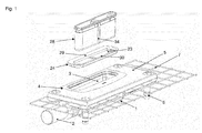
- a drain device comprises a drain housing 1, which via a Outlet nozzle 2 with an on-site drain pipe (not shown) can be connected.
- the drain housing 1 has on its upper side a water inlet opening 3 with a receiving part 4 surrounding this water inlet opening 3.
- the receiving part 4 is fixedly connected to the drain housing 1, for example glued. It is quite possible that the drain body 1 and the receiving part 4 are integrally formed, so that the receiving part 4 is designed as part of the drain body 1. In this case, the drain body 1, for example, have a water inlet opening 3 surrounding support shoulder.
- the upper end of the drain housing 1 and the receiving part 4 is surrounded by an inlet collar 5 (see Fig. 1 ).
- the inlet collar 5 is a substantially flat part with a rectangular outline.
- four support feet 6 are mounted, which are in particular height adjustable.
- the inlet collar 5 of this outwardly projecting grating 7 are connected, which surround the inlet collar 5 circumferentially.
- the grids 7 serve to anchor the drainage device better in a floor structure, where appropriate, by an inclination of the grid 7, an inclination of the floor tiles can be specified.
- the inlet collar 5 and the grid 7 are in the screed 8 (see Fig. 2 to Fig. 4 ).
- the drainage device further comprises a drainage channel 9 according to the invention, through which the water can enter the water inlet opening 3.
- the gutter 9 is open in the region of the water inlet opening 3 upwards and to the side facing away from the wall (see Fig. 4 ).
- the gutter 9 has in this area a substantially L-shaped cross section, with a vertical leg in the installed state 9a, which projects into the wall structure 10 upwards or ends below the bottom wall tile 16, and serving as a channel bottom 9b horizontal Legs in the area of the water inlet opening 3.
- the gutter 9 is designed differently outside the region of the water inlet opening 3. There it has, on the side opposite the vertical leg 9a, a side wall 9c which extends upwards from the channel bottom 9b and has a horizontal connecting section 9d extending below the floor tiles 20 (see FIG Fig. 3a and Fig. 10 ).
- the quadrilateral upwardly extending side wall 9c can prevent water from flowing out of the drainage channel 9 on the tide side.
- the below the floor tiles 20 extending horizontal connecting portion 9d is used to fix the gutter.
- the gutter 9 is integrated in the illustrated embodiment in the wall structure 10.
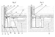
- the wall structure comprises from left to right in FIG Fig. 2 and Fig. 3 or from inside to outside the masonry wall 1 1, a plaster 12 applied thereto, a decoupling strip 13, a plurality of sealing tapes 14, a tile adhesive 15 and wall tiles 16 applied thereon.
- the gutter 9 lies with her in Fig. 2 to Fig. 4 left side or with its side facing the wall of the sealing strips 14, wherein the vertical leg 9a of the gutter 9 projects up behind the bottom wall tile 16 and is surrounded by two of the sealing bands 14. Alternatively, the vertical leg 9a may terminate below the lowermost wall tile 16.
- the horizontal leg of the gutter 9 serving as the channel bottom 9b is arranged below the lowermost wall tile 16 so that the gutter 9 does not protrude beyond the wall tile 16 into the space.
- a tile end strip 17 is arranged below the bottom wall tile 16.
- a drain opening 18 is formed through which water can flow into the integrated into the wall structure 10 gutter 9.
- a cover 19 is arranged, the top of which is in the illustrated embodiment at the same height as the top of the floor tiles 20. Accordingly, the water to be discharged can pass from the floor tiles 20 via the cover 19 through the drain opening 18 into the gutter 9. It is aligned in the Fig. 2 to Fig. 4 left or wall side of the cover 19 substantially with the in the Fig. 2 to Fig. 4 In this way, there is a drain opening 18, which is arranged as a narrow gap in the wall at its lower end (see, for example Fig. 2a and Fig. 4 ).
- the wall facing or in Fig. 2 to Fig. 4 left side of the cover 19 is tapered so that in the Drain 9 befindliches water under the chamfer 31 of the cover 19 can pass through to the water inlet opening 3.
- the cover 19 may be loose when installed on parts of the drainage device or the bottom, so that it can be removed upwards.
- the cover 19 is formed by a peripheral frame 21, in which an insert 22 can be introduced.
- the insert 22 may consist of the same material as the floor tiles. However, it can also be provided to shape the cover differently, for example as a one-piece part made of metal.
- the drainage device further comprises a receiving frame 24 provided with an opening 23, which is inserted into a recess of the receiving part 4 when installed.
- the receiving frame has an upper circumferential collar 25 and a downwardly extending from this in the installed state circumferential surface 26 (see Fig. 8 ).
- a circumferential seal 27 is arranged on the inside of the receiving part 4, which seals the receiving frame 24 against the receiving part 4.
- the seal 27 may be formed as a solid or loose seal.
- the receiving frame 24 may have a circumferential seal, not shown. This could be arranged on the underside of the collar 25 or on the outside of the surface 26. Alternatively, the receiving frame 24 can be glued into the receiving part 4. For this purpose, adhesive can be applied to the underside of the circumferential collar 25 and / or circumferentially on the vertical surface 26.
- the draining device further comprises an odor trap 28, which is held with its upper edge in the installed state in the opening 23 of the receiving frame 24, wherein the remaining portions of the odor trap 28 project through the receiving frame 24 down.
- the receiving frame 24 in the opening 23 protruding frontal peripheral shoulders 32 and a central transverse web 33 (see Fig. 7 ).
- the odor trap 28 has an incision 34 (see Fig. 1 ), in which the web 33 can engage.
- the opening 23 of the receiving frame 24 is oblong oval and bounded by lateral longitudinal sections 29, 30 (see, for example Fig. 1 and Fig. 5 ).
- the opening 23 is preferably not arranged symmetrically in the receiving frame 24 (see Fig. 1 ).
- the first longitudinal section 29 has a greater width than the second longitudinal section 30 (see also FIG FIGS. 7 and 8 ).
- FIG. 2a shows the first position of the receiving frame 24, in which the first, wider longitudinal portion 29 on the side facing away from the wall and the second, narrower longitudinal portion 30 is arranged on the wall side. In this first position, the opening 23 is thus comparatively close to the wall.
- the narrower longitudinal portion 30 is disposed on the side facing away from the wall and the first, wider longitudinal portion 29 on the wall side. In this second position, the opening 23 is thus relatively far away from the wall.
- Fig. 2a In the installation situation according to Fig. 2a is a thinner wall tile shown as in the installation situation according to Fig. 3a , It is found that it is ensured by the differently wide longitudinal sections 29, 30 and the various positions of the receiving frame 24 that the distance b 1 , b 2 between the wall-side boundary of the opening 23 and in the Fig. 2 to Fig. 4 right side or wall facing away from the wall tiles 16 in both cases is sufficiently large to remove the odor trap 28 after removing the cover 19 upwards.
- Fig. 6 to Fig. 8 each show two different receiving frame 24, 24 '. These receiving frames 24, 24 'differ by different widths of both the first longitudinal sections 29, 29', and the second longitudinal sections 30, 30 '.
- the in Fig. 7 left receiving frame 24 has with the first longitudinal portion 29 on the widest longitudinal portion, which accordingly can ensure a very far from the wall spaced position of the opening 23.
- the in Fig. 7 right receiving frame 24 ' has a slightly less wide first longitudinal portion 29', which can ensure a slightly less far from the wall spaced position of the opening 23 '.
- the in Fig. 7 right receiving frame 24 'further has a only slightly narrower second longitudinal portion 30', which has a slightly closer to the wall disposed position of the opening 23 ' can guarantee.
- the in Fig. 7 left receiving frame 24 has with the second longitudinal portion 30 and the narrowest longitudinal portion, which accordingly can ensure a very close to the wall arranged position of the opening 23.
- the user is thus given the opportunity to better adapt the distance a 1 , a 2 of the opening 23, 23' or the odor trap 28 from the wall to the local conditions.
- a drainage device takes place in that in a first method step, the drain housing 1 is mounted on the raw floor before the application of the screed and connected to a drain pipe. Subsequently, the screed is applied to the subfloor, so that the inlet collar and the grid are at least partially surrounded by the screed. Subsequently, the entire floor and wall area including the already installed drainage parts are sealed.
- the gutter 9 is mounted adjacent to the plastered wall, in particular together with sealing strips 14. Subsequently, the wall tiles 16 are applied, whereby the vertical leg 9a of the gutter 9 can be optionally covered.
- the receiving frame 24 is used so that the wall-side end of the inserted into the receiving frame 24 odor trap 28 in the horizontal direction has a sufficient distance b 1 , b 2 from the outside of the wall tile 16 so that it can still be removed upwards.
- the receiving frame 24, 24 ' is glued in the receiving part 4 or the top of the overflow housing 1 or secured by seals 27.
- the odor trap 28 is used and on the top of the odor trap 28, the cover 19 is loosely placed.
- the floor tiles 20 can be suitably worked on the cover 19.
- This design ensures that the odor trap 28 can be removed and cleaned at any time after removal of the cover 19 despite the very near-wall installation of the drainage device.
- Fig. 9 shows the drain device in the installed state.
- Fig. 9 are a gutter 9 according to the invention, the cover 19, the slot-shaped drain opening 18 and the wall tiles 16 and the floor tiles visible.
- the cover is arranged only in the central region of the gutter 9.
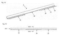
- FIG. 10 and FIG. 15 show that the illustrated embodiment of a gutter according to the invention 9 in the longitudinal direction into three sections 35, 36, 37 is divided.
- the middle section 36 is located in the region of the water inlet opening 3
- the outer sections 35, 37 are arranged outside the region of the water inlet opening 3 or the cover 19.
- the gutter 9 has a substantially L-shaped cross section, with the vertical leg 9a in the installed state, which projects into the wall structure 10 upwards or ends below the bottom wall tile 16, and a serving as gutter bottom 9b horizontal leg.
- the water can emerge directly horizontally to the side from the gutter 9, because in the central region 36 no vertical leg 9a opposite side wall 9c is provided.
- the side wall 9c formed in the two outer portions 35, 37 and formed by the quarter-circle upwardly extending portion is cut out or omitted (see FIG Fig. 10 and Fig. 17 ). Further, in the middle portion 36, the horizontal connection portion 9d extending below the floor tiles 20 is also omitted.
- the connecting portion 9d provided in the outer portions 35, 37 has openings 38 through which tile adhesives can pass to secure the gutter 9 to the top of the screed or sealing layers disposed thereon.
- the channel bottom 9b has in the two outer sections 35, 37 a gradient in the longitudinal direction to the central portion 36 toward.
- Fig. 16 shows that the illustrated embodiment of the gutter 9 consists of two interconnected parts 39, 40.
- the first part 39 comprises two in Fig. 16 outer portions of the vertical leg 9a, which merge into one another by folding up, and an upper portion of the gutter bottom 9b and the side wall 9c.
- the second part 40 comprises an in Fig. 16 inner portion of the vertical leg 9a, a lower portion of the gutter bottom 9b and the connecting portion 9d.
- the second part 40 associated portion of the vertical leg 9a extends between the two portions of the vertical leg 9a associated with the first part 39 (see FIG Fig. 16 ).
- the design of the gutter 9 from the two described parts 39, 40 offers manufacturing advantages because the two parts 39, 40 made separately from each other and can be relatively easily assembled to the gutter 9.
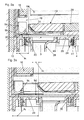
- the 11 to FIG. 14 show an embodiment of a simpler drainage device, wherein the odor trap 28 can not be installed in two different positions. Furthermore, the vertical leg 9a of the gutter 9 does not protrude beyond the lowermost wall tile 16 into the construction of the sealing tapes, but ends below the lowermost wall tile 16.
- FIG. 11 and FIG. 12 show the drainage device in the region of one of the outer portions 35, 37 of the gutter 9. In this area, although water can run through the drain opening 18 into the gutter 9. However, the water can not run out laterally, because in this area the side wall 9c is provided. In the Fig. 12 The outside of the side wall 9c arranged on the right can serve as a contact surface for the floor tiles 20.
- the water runs from the outer sections 35, 37 because of the slope of the gutter bottom 9b on this in the middle portion 36 of the gutter 9.
- This middle portion 36 of the gutter 9 and the associated portion of the drain device are in FIGS. 13 and 14 shown.
- the side wall 9 c is not provided, so that the water can pass under the chamfer 31 of the cover 19 through to the water inlet opening 3.
- the gutter 9 is according to the 11 to FIG. 14 in a space between the bottom of the bottom wall tile 16 and optionally provided with a seal surface of the screed 8 is arranged.
- the height H of the gutter 9, so the distance from the bottom of the gutter bottom 9b to the top of the vertical leg 9a (see, for example Fig. 16 ) should therefore be less than about 5 cm, preferably less than about 3 cm.
- the gutter 9 is according to the 11 to FIG. 14 in a space between the outside of the next floor tile 20 and optionally provided with a sealing strip 14 surface of the plaster 12 wall 10 is arranged.
- the depth T 2 of the gutter 9, so the distance from the in Fig. 17 left rear side of the vertical leg 9a to the in Fig. 17 should therefore be, in particular, smaller than approximately 5 cm, preferably smaller than approximately 3 cm.
- the depth T 1 of the gutter 9, so the distance from the in Fig. 17 therefore, in particular be smaller than about 5 cm, preferably less than about 3 cm to the room-side end of the trough bottom 9b arranged on the left rear side of the vertical leg 9a.
Landscapes
- Health & Medical Sciences (AREA)
- Life Sciences & Earth Sciences (AREA)
- Engineering & Computer Science (AREA)
- Hydrology & Water Resources (AREA)
- Public Health (AREA)
- Water Supply & Treatment (AREA)
- Sink And Installation For Waste Water (AREA)
- Building Environments (AREA)
Priority Applications (3)
| Application Number | Priority Date | Filing Date | Title |
|---|---|---|---|
| PL13158630T PL2765250T3 (pl) | 2013-02-07 | 2013-03-11 | Rynna odpływowa |
| SI201331747T SI2765250T1 (sl) | 2013-02-07 | 2013-03-11 | Odtočni kanal |
| DE202014100552.8U DE202014100552U1 (de) | 2013-02-07 | 2014-02-07 | Ablaufvorrichtung |
Applications Claiming Priority (1)
| Application Number | Priority Date | Filing Date | Title |
|---|---|---|---|
| DE102013101207.8A DE102013101207A1 (de) | 2013-02-07 | 2013-02-07 | Ablaufvorrichtung |
Publications (2)
| Publication Number | Publication Date |
|---|---|
| EP2765250A1 true EP2765250A1 (fr) | 2014-08-13 |
| EP2765250B1 EP2765250B1 (fr) | 2020-06-10 |
Family
ID=47844201
Family Applications (1)
| Application Number | Title | Priority Date | Filing Date |
|---|---|---|---|
| EP13158630.7A Active EP2765250B1 (fr) | 2013-02-07 | 2013-03-11 | Rigole d'écoulement |
Country Status (8)
| Country | Link |
|---|---|
| EP (1) | EP2765250B1 (fr) |
| DE (1) | DE102013101207A1 (fr) |
| DK (1) | DK2765250T3 (fr) |
| ES (1) | ES2804264T3 (fr) |
| HU (1) | HUE049676T2 (fr) |
| PL (1) | PL2765250T3 (fr) |
| PT (1) | PT2765250T (fr) |
| SI (1) | SI2765250T1 (fr) |
Cited By (2)
| Publication number | Priority date | Publication date | Assignee | Title |
|---|---|---|---|---|
| FR3026420A1 (fr) * | 2014-09-30 | 2016-04-01 | Fr D Assainissement Sfa Soc | Caniveau et receveur de douche |
| DE102015109211A1 (de) | 2015-06-10 | 2016-12-15 | Dallmer Gmbh & Co. Kg | Ablaufrinne |
Families Citing this family (2)
| Publication number | Priority date | Publication date | Assignee | Title |
|---|---|---|---|---|
| DE102014013135A1 (de) | 2014-09-10 | 2016-03-10 | Viega Gmbh & Co. Kg | Wandablaufrinne für eine Dusche |
| DE102015104598A1 (de) | 2015-03-26 | 2016-09-29 | Dallmer Gmbh & Co. Kg | Ablaufvorrichtung, Ablaufanordnung sowie Verfahren zur Herstellung einer Ablaufanordnung |
Citations (3)
| Publication number | Priority date | Publication date | Assignee | Title |
|---|---|---|---|---|
| US6014780A (en) * | 1998-05-04 | 2000-01-18 | Eagle Natural Stone | Shower bath and drain |
| WO2005111327A1 (fr) * | 2004-05-13 | 2005-11-24 | Aachen Industries Pty Ltd | Ensemble fente-drain |
| DE202005019964U1 (de) * | 2005-12-21 | 2006-03-02 | Kessel Gmbh | Ablaufsystem |
Family Cites Families (4)
| Publication number | Priority date | Publication date | Assignee | Title |
|---|---|---|---|---|
| DE9419373U1 (de) * | 1994-12-05 | 1995-03-16 | Wilhelm Hafner GmbH, 78479 Reichenau | Rinne zum Verlegen in einem Fußboden |
| EP0893545B1 (fr) * | 1997-07-23 | 2004-11-24 | Blücher Germany GmbH | Caniveau à encastrer pour la pose dans le sol |
| DE202010017610U1 (de) * | 2010-06-16 | 2012-03-14 | Buchberger Gmbh Profilsysteme | Ablaufrinne |
| NL2005949C2 (nl) * | 2011-01-04 | 2012-07-05 | Easy Sanitairy Solutions Bv | Afvoer met unidirectionele afwatering. |
-
2013
- 2013-02-07 DE DE102013101207.8A patent/DE102013101207A1/de active Pending
- 2013-03-11 EP EP13158630.7A patent/EP2765250B1/fr active Active
- 2013-03-11 PL PL13158630T patent/PL2765250T3/pl unknown
- 2013-03-11 DK DK13158630.7T patent/DK2765250T3/da active
- 2013-03-11 SI SI201331747T patent/SI2765250T1/sl unknown
- 2013-03-11 PT PT131586307T patent/PT2765250T/pt unknown
- 2013-03-11 ES ES13158630T patent/ES2804264T3/es active Active
- 2013-03-11 HU HUE13158630A patent/HUE049676T2/hu unknown
Patent Citations (3)
| Publication number | Priority date | Publication date | Assignee | Title |
|---|---|---|---|---|
| US6014780A (en) * | 1998-05-04 | 2000-01-18 | Eagle Natural Stone | Shower bath and drain |
| WO2005111327A1 (fr) * | 2004-05-13 | 2005-11-24 | Aachen Industries Pty Ltd | Ensemble fente-drain |
| DE202005019964U1 (de) * | 2005-12-21 | 2006-03-02 | Kessel Gmbh | Ablaufsystem |
Cited By (2)
| Publication number | Priority date | Publication date | Assignee | Title |
|---|---|---|---|---|
| FR3026420A1 (fr) * | 2014-09-30 | 2016-04-01 | Fr D Assainissement Sfa Soc | Caniveau et receveur de douche |
| DE102015109211A1 (de) | 2015-06-10 | 2016-12-15 | Dallmer Gmbh & Co. Kg | Ablaufrinne |
Also Published As
| Publication number | Publication date |
|---|---|
| DK2765250T3 (da) | 2020-07-13 |
| SI2765250T1 (sl) | 2020-09-30 |
| HUE049676T2 (hu) | 2020-10-28 |
| DE102013101207A1 (de) | 2014-08-21 |
| ES2804264T3 (es) | 2021-02-05 |
| PL2765250T3 (pl) | 2020-11-16 |
| EP2765250B1 (fr) | 2020-06-10 |
| PT2765250T (pt) | 2020-07-13 |
Similar Documents
| Publication | Publication Date | Title |
|---|---|---|
| EP3031990B1 (fr) | Siphon de sol | |
| EP2315544B1 (fr) | Élément receveur de douche en mousse | |
| EP2085006B1 (fr) | Elément de sol de douche | |
| EP2664722B1 (fr) | Bouche d'égout avec couvercle destiné à recevoir un carrelage | |
| WO2017067717A1 (fr) | Écoulement de sol comportant une garniture cylindrique fixée à celui-ci | |
| DE202014007357U1 (de) | Bodenablauf mit Dichtungsmatte | |
| EP3705655A1 (fr) | Écoulement au sol permettant d'évacuer l'eau d'un sol praticable dans une conduites des eaux usées | |
| EP2765250B1 (fr) | Rigole d'écoulement | |
| EP2227997A1 (fr) | Elément de base pour douche fabriqué en mousse | |
| DE202014100552U1 (de) | Ablaufvorrichtung | |
| EP2278081B1 (fr) | Cadre de connection pour une bouche d'écoulement et bouche d'écoulement | |
| EP2634321B1 (fr) | Rigole d'écoulement | |
| DE29514797U1 (de) | Abschlußprofilsystem für Balkone, Terrassen u.dgl. | |
| DE202016104882U1 (de) | Ablaufeinheit und Ablaufvorrichtung zur Ableitung von Wasser | |
| DE102012106924A1 (de) | Ablaufanordnung | |
| DE202014007356U1 (de) | Wasserablauf mit Einsatz | |
| DE202014007391U1 (de) | Bodenablauf mit Einlauftrichter | |
| EP3388577A1 (fr) | Système de drainage | |
| EP3375944B1 (fr) | Conduite de drainage, procédé de fabrication et procédé de montage | |
| DE102017111331B4 (de) | Entwässerungsrinne, Verfahren zur Herstellung | |
| DE202015105639U1 (de) | Bodenablauf mit Geruchsverschluss | |
| EP2759646B1 (fr) | Dispositif pour une évacuation de sol disposée à proximité d'un mur | |
| DE202011004001U1 (de) | Ablaufanordnung | |
| DE29617121U1 (de) | Entwässerungsrinne für den Einbau vor Tür- oder Fensterelementen | |
| EP2995730B1 (fr) | Bouche d'égout avec un entonnoir d'entrée |
Legal Events
| Date | Code | Title | Description |
|---|---|---|---|
| PUAI | Public reference made under article 153(3) epc to a published international application that has entered the european phase |
Free format text: ORIGINAL CODE: 0009012 |
|
| 17P | Request for examination filed |
Effective date: 20140409 |
|
| AK | Designated contracting states |
Kind code of ref document: A1 Designated state(s): AL AT BE BG CH CY CZ DE DK EE ES FI FR GB GR HR HU IE IS IT LI LT LU LV MC MK MT NL NO PL PT RO RS SE SI SK SM TR |
|
| AX | Request for extension of the european patent |
Extension state: BA ME |
|
| RBV | Designated contracting states (corrected) |
Designated state(s): AL AT BE BG CH CY CZ DE DK EE ES FI FR GB GR HR HU IE IS IT LI LT LU LV MC MK MT NL NO PL PT RO RS SE SI SK SM TR |
|
| APBK | Appeal reference recorded |
Free format text: ORIGINAL CODE: EPIDOSNREFNE |
|
| APBN | Date of receipt of notice of appeal recorded |
Free format text: ORIGINAL CODE: EPIDOSNNOA2E |
|
| APBR | Date of receipt of statement of grounds of appeal recorded |
Free format text: ORIGINAL CODE: EPIDOSNNOA3E |
|
| APAF | Appeal reference modified |
Free format text: ORIGINAL CODE: EPIDOSCREFNE |
|
| APBT | Appeal procedure closed |
Free format text: ORIGINAL CODE: EPIDOSNNOA9E |
|
| STAA | Information on the status of an ep patent application or granted ep patent |
Free format text: STATUS: EXAMINATION IS IN PROGRESS |
|
| GRAP | Despatch of communication of intention to grant a patent |
Free format text: ORIGINAL CODE: EPIDOSNIGR1 |
|
| STAA | Information on the status of an ep patent application or granted ep patent |
Free format text: STATUS: GRANT OF PATENT IS INTENDED |
|
| INTG | Intention to grant announced |
Effective date: 20200212 |
|
| GRAS | Grant fee paid |
Free format text: ORIGINAL CODE: EPIDOSNIGR3 |
|
| GRAA | (expected) grant |
Free format text: ORIGINAL CODE: 0009210 |
|
| STAA | Information on the status of an ep patent application or granted ep patent |
Free format text: STATUS: THE PATENT HAS BEEN GRANTED |
|
| AK | Designated contracting states |
Kind code of ref document: B1 Designated state(s): AL AT BE BG CH CY CZ DE DK EE ES FI FR GB GR HR HU IE IS IT LI LT LU LV MC MK MT NL NO PL PT RO RS SE SI SK SM TR |
|
| REG | Reference to a national code |
Ref country code: GB Ref legal event code: FG4D Free format text: NOT ENGLISH |
|
| REG | Reference to a national code |
Ref country code: AT Ref legal event code: REF Ref document number: 1279311 Country of ref document: AT Kind code of ref document: T Effective date: 20200615 Ref country code: CH Ref legal event code: EP |
|
| REG | Reference to a national code |
Ref country code: DE Ref legal event code: R096 Ref document number: 502013014778 Country of ref document: DE |
|
| REG | Reference to a national code |
Ref country code: IE Ref legal event code: FG4D Free format text: LANGUAGE OF EP DOCUMENT: GERMAN |
|
| REG | Reference to a national code |
Ref country code: DK Ref legal event code: T3 Effective date: 20200709 Ref country code: PT Ref legal event code: SC4A Ref document number: 2765250 Country of ref document: PT Date of ref document: 20200713 Kind code of ref document: T Free format text: AVAILABILITY OF NATIONAL TRANSLATION Effective date: 20200706 |
|
| REG | Reference to a national code |
Ref country code: NL Ref legal event code: FP |
|
| REG | Reference to a national code |
Ref country code: SE Ref legal event code: TRGR |
|
| REG | Reference to a national code |
Ref country code: NO Ref legal event code: T2 Effective date: 20200610 |
|
| REG | Reference to a national code |
Ref country code: SK Ref legal event code: T3 Ref document number: E 34792 Country of ref document: SK |
|
| REG | Reference to a national code |
Ref country code: LT Ref legal event code: MG4D |
|
| REG | Reference to a national code |
Ref country code: HU Ref legal event code: AG4A Ref document number: E049676 Country of ref document: HU |
|
| PG25 | Lapsed in a contracting state [announced via postgrant information from national office to epo] |
Ref country code: FI Free format text: LAPSE BECAUSE OF FAILURE TO SUBMIT A TRANSLATION OF THE DESCRIPTION OR TO PAY THE FEE WITHIN THE PRESCRIBED TIME-LIMIT Effective date: 20200610 Ref country code: LT Free format text: LAPSE BECAUSE OF FAILURE TO SUBMIT A TRANSLATION OF THE DESCRIPTION OR TO PAY THE FEE WITHIN THE PRESCRIBED TIME-LIMIT Effective date: 20200610 Ref country code: GR Free format text: LAPSE BECAUSE OF FAILURE TO SUBMIT A TRANSLATION OF THE DESCRIPTION OR TO PAY THE FEE WITHIN THE PRESCRIBED TIME-LIMIT Effective date: 20200911 |
|
| PG25 | Lapsed in a contracting state [announced via postgrant information from national office to epo] |
Ref country code: BG Free format text: LAPSE BECAUSE OF FAILURE TO SUBMIT A TRANSLATION OF THE DESCRIPTION OR TO PAY THE FEE WITHIN THE PRESCRIBED TIME-LIMIT Effective date: 20200910 Ref country code: RS Free format text: LAPSE BECAUSE OF FAILURE TO SUBMIT A TRANSLATION OF THE DESCRIPTION OR TO PAY THE FEE WITHIN THE PRESCRIBED TIME-LIMIT Effective date: 20200610 Ref country code: HR Free format text: LAPSE BECAUSE OF FAILURE TO SUBMIT A TRANSLATION OF THE DESCRIPTION OR TO PAY THE FEE WITHIN THE PRESCRIBED TIME-LIMIT Effective date: 20200610 Ref country code: LV Free format text: LAPSE BECAUSE OF FAILURE TO SUBMIT A TRANSLATION OF THE DESCRIPTION OR TO PAY THE FEE WITHIN THE PRESCRIBED TIME-LIMIT Effective date: 20200610 |
|
| PG25 | Lapsed in a contracting state [announced via postgrant information from national office to epo] |
Ref country code: AL Free format text: LAPSE BECAUSE OF FAILURE TO SUBMIT A TRANSLATION OF THE DESCRIPTION OR TO PAY THE FEE WITHIN THE PRESCRIBED TIME-LIMIT Effective date: 20200610 |
|
| PG25 | Lapsed in a contracting state [announced via postgrant information from national office to epo] |
Ref country code: EE Free format text: LAPSE BECAUSE OF FAILURE TO SUBMIT A TRANSLATION OF THE DESCRIPTION OR TO PAY THE FEE WITHIN THE PRESCRIBED TIME-LIMIT Effective date: 20200610 Ref country code: RO Free format text: LAPSE BECAUSE OF FAILURE TO SUBMIT A TRANSLATION OF THE DESCRIPTION OR TO PAY THE FEE WITHIN THE PRESCRIBED TIME-LIMIT Effective date: 20200610 Ref country code: SM Free format text: LAPSE BECAUSE OF FAILURE TO SUBMIT A TRANSLATION OF THE DESCRIPTION OR TO PAY THE FEE WITHIN THE PRESCRIBED TIME-LIMIT Effective date: 20200610 |
|
| REG | Reference to a national code |
Ref country code: ES Ref legal event code: FG2A Ref document number: 2804264 Country of ref document: ES Kind code of ref document: T3 Effective date: 20210205 |
|
| PG25 | Lapsed in a contracting state [announced via postgrant information from national office to epo] |
Ref country code: IS Free format text: LAPSE BECAUSE OF FAILURE TO SUBMIT A TRANSLATION OF THE DESCRIPTION OR TO PAY THE FEE WITHIN THE PRESCRIBED TIME-LIMIT Effective date: 20201010 |
|
| REG | Reference to a national code |
Ref country code: DE Ref legal event code: R097 Ref document number: 502013014778 Country of ref document: DE |
|
| PLBE | No opposition filed within time limit |
Free format text: ORIGINAL CODE: 0009261 |
|
| STAA | Information on the status of an ep patent application or granted ep patent |
Free format text: STATUS: NO OPPOSITION FILED WITHIN TIME LIMIT |
|
| PGFP | Annual fee paid to national office [announced via postgrant information from national office to epo] |
Ref country code: MC Payment date: 20210323 Year of fee payment: 9 Ref country code: LU Payment date: 20210319 Year of fee payment: 9 |
|
| 26N | No opposition filed |
Effective date: 20210311 |
|
| PG25 | Lapsed in a contracting state [announced via postgrant information from national office to epo] |
Ref country code: HU Free format text: LAPSE BECAUSE OF NON-PAYMENT OF DUE FEES Effective date: 20210312 |
|
| PGFP | Annual fee paid to national office [announced via postgrant information from national office to epo] |
Ref country code: IE Payment date: 20220322 Year of fee payment: 10 Ref country code: DK Payment date: 20220323 Year of fee payment: 10 |
|
| PGFP | Annual fee paid to national office [announced via postgrant information from national office to epo] |
Ref country code: PT Payment date: 20220303 Year of fee payment: 10 |
|
| PGFP | Annual fee paid to national office [announced via postgrant information from national office to epo] |
Ref country code: SI Payment date: 20220309 Year of fee payment: 10 |
|
| PG25 | Lapsed in a contracting state [announced via postgrant information from national office to epo] |
Ref country code: MC Free format text: LAPSE BECAUSE OF NON-PAYMENT OF DUE FEES Effective date: 20220331 |
|
| PG25 | Lapsed in a contracting state [announced via postgrant information from national office to epo] |
Ref country code: LU Free format text: LAPSE BECAUSE OF NON-PAYMENT OF DUE FEES Effective date: 20220311 |
|
| PG25 | Lapsed in a contracting state [announced via postgrant information from national office to epo] |
Ref country code: CY Free format text: LAPSE BECAUSE OF FAILURE TO SUBMIT A TRANSLATION OF THE DESCRIPTION OR TO PAY THE FEE WITHIN THE PRESCRIBED TIME-LIMIT Effective date: 20200610 |
|
| P01 | Opt-out of the competence of the unified patent court (upc) registered |
Effective date: 20230616 |
|
| PG25 | Lapsed in a contracting state [announced via postgrant information from national office to epo] |
Ref country code: PT Free format text: LAPSE BECAUSE OF NON-PAYMENT OF DUE FEES Effective date: 20230911 |
|
| REG | Reference to a national code |
Ref country code: DK Ref legal event code: EBP Effective date: 20230331 |
|
| REG | Reference to a national code |
Ref country code: SI Ref legal event code: KO00 Effective date: 20231122 |
|
| REG | Reference to a national code |
Ref country code: IE Ref legal event code: MM4A |
|
| PG25 | Lapsed in a contracting state [announced via postgrant information from national office to epo] |
Ref country code: SI Free format text: LAPSE BECAUSE OF NON-PAYMENT OF DUE FEES Effective date: 20230312 Ref country code: IE Free format text: LAPSE BECAUSE OF NON-PAYMENT OF DUE FEES Effective date: 20230311 |
|
| PGFP | Annual fee paid to national office [announced via postgrant information from national office to epo] |
Ref country code: NL Payment date: 20240320 Year of fee payment: 12 |
|
| PGFP | Annual fee paid to national office [announced via postgrant information from national office to epo] |
Ref country code: AT Payment date: 20240321 Year of fee payment: 12 |
|
| PG25 | Lapsed in a contracting state [announced via postgrant information from national office to epo] |
Ref country code: MK Free format text: LAPSE BECAUSE OF FAILURE TO SUBMIT A TRANSLATION OF THE DESCRIPTION OR TO PAY THE FEE WITHIN THE PRESCRIBED TIME-LIMIT Effective date: 20200610 Ref country code: DK Free format text: LAPSE BECAUSE OF NON-PAYMENT OF DUE FEES Effective date: 20230331 |
|
| PGFP | Annual fee paid to national office [announced via postgrant information from national office to epo] |
Ref country code: DE Payment date: 20240331 Year of fee payment: 12 Ref country code: CZ Payment date: 20240304 Year of fee payment: 12 Ref country code: GB Payment date: 20240320 Year of fee payment: 12 Ref country code: SK Payment date: 20240304 Year of fee payment: 12 |
|
| PGFP | Annual fee paid to national office [announced via postgrant information from national office to epo] |
Ref country code: TR Payment date: 20240304 Year of fee payment: 12 Ref country code: SE Payment date: 20240320 Year of fee payment: 12 Ref country code: PL Payment date: 20240305 Year of fee payment: 12 Ref country code: NO Payment date: 20240322 Year of fee payment: 12 Ref country code: IT Payment date: 20240322 Year of fee payment: 12 Ref country code: FR Payment date: 20240327 Year of fee payment: 12 Ref country code: BE Payment date: 20240320 Year of fee payment: 12 |
|
| PGFP | Annual fee paid to national office [announced via postgrant information from national office to epo] |
Ref country code: CH Payment date: 20240401 Year of fee payment: 12 |
|
| PGFP | Annual fee paid to national office [announced via postgrant information from national office to epo] |
Ref country code: ES Payment date: 20240426 Year of fee payment: 12 |