EP2765095B1 - Scharniersystem und faltbarer behälter - Google Patents
Scharniersystem und faltbarer behälter Download PDFInfo
- Publication number
- EP2765095B1 EP2765095B1 EP12836349.6A EP12836349A EP2765095B1 EP 2765095 B1 EP2765095 B1 EP 2765095B1 EP 12836349 A EP12836349 A EP 12836349A EP 2765095 B1 EP2765095 B1 EP 2765095B1
- Authority
- EP
- European Patent Office
- Prior art keywords
- slot
- pin
- component
- pit
- hinge system
- Prior art date
- Legal status (The legal status is an assumption and is not a legal conclusion. Google has not performed a legal analysis and makes no representation as to the accuracy of the status listed.)
- Active
Links
Images


Classifications
-
- B—PERFORMING OPERATIONS; TRANSPORTING
- B65—CONVEYING; PACKING; STORING; HANDLING THIN OR FILAMENTARY MATERIAL
- B65D—CONTAINERS FOR STORAGE OR TRANSPORT OF ARTICLES OR MATERIALS, e.g. BAGS, BARRELS, BOTTLES, BOXES, CANS, CARTONS, CRATES, DRUMS, JARS, TANKS, HOPPERS, FORWARDING CONTAINERS; ACCESSORIES, CLOSURES, OR FITTINGS THEREFOR; PACKAGING ELEMENTS; PACKAGES
- B65D21/00—Nestable, stackable or joinable containers; Containers of variable capacity
- B65D21/08—Containers of variable capacity
- B65D21/086—Collapsible or telescopic containers
-
- B—PERFORMING OPERATIONS; TRANSPORTING
- B65—CONVEYING; PACKING; STORING; HANDLING THIN OR FILAMENTARY MATERIAL
- B65D—CONTAINERS FOR STORAGE OR TRANSPORT OF ARTICLES OR MATERIALS, e.g. BAGS, BARRELS, BOTTLES, BOXES, CANS, CARTONS, CRATES, DRUMS, JARS, TANKS, HOPPERS, FORWARDING CONTAINERS; ACCESSORIES, CLOSURES, OR FITTINGS THEREFOR; PACKAGING ELEMENTS; PACKAGES
- B65D19/00—Pallets or like platforms, with or without side walls, for supporting loads to be lifted or lowered
- B65D19/02—Rigid pallets with side walls, e.g. box pallets
- B65D19/06—Rigid pallets with side walls, e.g. box pallets with bodies formed by uniting or interconnecting two or more components
-
- E—FIXED CONSTRUCTIONS
- E05—LOCKS; KEYS; WINDOW OR DOOR FITTINGS; SAFES
- E05D—HINGES OR SUSPENSION DEVICES FOR DOORS, WINDOWS OR WINGS
- E05D3/00—Hinges with pins
- E05D3/06—Hinges with pins with two or more pins
-
- B—PERFORMING OPERATIONS; TRANSPORTING
- B65—CONVEYING; PACKING; STORING; HANDLING THIN OR FILAMENTARY MATERIAL
- B65D—CONTAINERS FOR STORAGE OR TRANSPORT OF ARTICLES OR MATERIALS, e.g. BAGS, BARRELS, BOTTLES, BOXES, CANS, CARTONS, CRATES, DRUMS, JARS, TANKS, HOPPERS, FORWARDING CONTAINERS; ACCESSORIES, CLOSURES, OR FITTINGS THEREFOR; PACKAGING ELEMENTS; PACKAGES
- B65D2519/00—Pallets or like platforms, with or without side walls, for supporting loads to be lifted or lowered
- B65D2519/00004—Details relating to pallets
- B65D2519/00547—Connections
- B65D2519/00577—Connections structures connecting side walls, including corner posts, to each other
- B65D2519/00582—Connections structures connecting side walls, including corner posts, to each other structures intended to be disassembled, i.e. collapsible or dismountable
-
- B—PERFORMING OPERATIONS; TRANSPORTING
- B65—CONVEYING; PACKING; STORING; HANDLING THIN OR FILAMENTARY MATERIAL
- B65D—CONTAINERS FOR STORAGE OR TRANSPORT OF ARTICLES OR MATERIALS, e.g. BAGS, BARRELS, BOTTLES, BOXES, CANS, CARTONS, CRATES, DRUMS, JARS, TANKS, HOPPERS, FORWARDING CONTAINERS; ACCESSORIES, CLOSURES, OR FITTINGS THEREFOR; PACKAGING ELEMENTS; PACKAGES
- B65D2519/00—Pallets or like platforms, with or without side walls, for supporting loads to be lifted or lowered
- B65D2519/00004—Details relating to pallets
- B65D2519/00547—Connections
- B65D2519/00636—Connections structures connecting side walls to the pallet
- B65D2519/00641—Structures intended to be disassembled
- B65D2519/00646—Structures intended to be disassembled by means of hinges
- B65D2519/00651—Structures intended to be disassembled by means of hinges integrally formed
-
- B—PERFORMING OPERATIONS; TRANSPORTING
- B65—CONVEYING; PACKING; STORING; HANDLING THIN OR FILAMENTARY MATERIAL
- B65D—CONTAINERS FOR STORAGE OR TRANSPORT OF ARTICLES OR MATERIALS, e.g. BAGS, BARRELS, BOTTLES, BOXES, CANS, CARTONS, CRATES, DRUMS, JARS, TANKS, HOPPERS, FORWARDING CONTAINERS; ACCESSORIES, CLOSURES, OR FITTINGS THEREFOR; PACKAGING ELEMENTS; PACKAGES
- B65D2519/00—Pallets or like platforms, with or without side walls, for supporting loads to be lifted or lowered
- B65D2519/00004—Details relating to pallets
- B65D2519/00736—Details
- B65D2519/00805—Means for facilitating the removal of the load
-
- B—PERFORMING OPERATIONS; TRANSPORTING
- B65—CONVEYING; PACKING; STORING; HANDLING THIN OR FILAMENTARY MATERIAL
- B65D—CONTAINERS FOR STORAGE OR TRANSPORT OF ARTICLES OR MATERIALS, e.g. BAGS, BARRELS, BOTTLES, BOXES, CANS, CARTONS, CRATES, DRUMS, JARS, TANKS, HOPPERS, FORWARDING CONTAINERS; ACCESSORIES, CLOSURES, OR FITTINGS THEREFOR; PACKAGING ELEMENTS; PACKAGES
- B65D2519/00—Pallets or like platforms, with or without side walls, for supporting loads to be lifted or lowered
- B65D2519/00004—Details relating to pallets
- B65D2519/00736—Details
- B65D2519/00865—Collapsible, i.e. at least two constitutive elements remaining hingedly connected
- B65D2519/00875—Collapsible, i.e. at least two constitutive elements remaining hingedly connected collapsible side walls
- B65D2519/009—Collapsible, i.e. at least two constitutive elements remaining hingedly connected collapsible side walls whereby all side walls are hingedly connected to the base panel
-
- B—PERFORMING OPERATIONS; TRANSPORTING
- B65—CONVEYING; PACKING; STORING; HANDLING THIN OR FILAMENTARY MATERIAL
- B65D—CONTAINERS FOR STORAGE OR TRANSPORT OF ARTICLES OR MATERIALS, e.g. BAGS, BARRELS, BOTTLES, BOXES, CANS, CARTONS, CRATES, DRUMS, JARS, TANKS, HOPPERS, FORWARDING CONTAINERS; ACCESSORIES, CLOSURES, OR FITTINGS THEREFOR; PACKAGING ELEMENTS; PACKAGES
- B65D2519/00—Pallets or like platforms, with or without side walls, for supporting loads to be lifted or lowered
- B65D2519/00004—Details relating to pallets
- B65D2519/00736—Details
- B65D2519/00935—Details with special means for nesting or stacking
- B65D2519/00955—Details with special means for nesting or stacking stackable
- B65D2519/00965—Details with special means for nesting or stacking stackable when loaded
- B65D2519/00975—Details with special means for nesting or stacking stackable when loaded through the side walls
Definitions
- the disclosure relates to a hinge system for connecting two components and a collapsible container.
- collapsible side walls thereby reducing the space occupied by the container during transport.
- Most of these collapsible containers comprise a base in form of rectangular plate structure, wherein the collapsible side walls are coupled to the edges of the base by hinges. The side walls may be interlocked when the container stay erected, usually through engaging the latch of one side wall with the hook of another side wall.
- the side walls are configured to be higher than half of the width of the base, thus the opposite side walls will be overlapped when they are folded towards each other. Therefore, the side wall which is folded later will go beyond the edge of the side wall which is folded first and will be not parallel to the base but angled.
- the upper side walls will be bent and deformed or damaged with time elapses.
- another drawback is that several containers cannot be stacked in a stable way.
- one solution is to connect the side walls to the rods of the base at different height respectively.
- the height of the opposite side walls are different, which leads to increase the cost of manufacturing and maintaining.
- the workers must pay more attention during the operation which will affect the efficiency to some extend, since the folding work should be executed sequentially. It needs a more advanced alternative solution to solve this problem.
- US5938059A disclosed a solution to solve the above problems.
- One side all and the opposite side wall may overlap each other in a manner that the side walls are placed parallel to the base and the folding order is not limited through an oval hole provided on the base and a pin the base of the match, the pin being able to move up and down in the oval hole within a distance.
- This invention solves the problem of folding container to a certain extent. Also, the side walls of container are same with each other. However, it needs additional pins or tubes as pivot shafts and tools should be used to operate the pivot shafts when assembly or disassembly the side walls, which will lower the efficiency.
- WO2005102850A1 proposed a more advanced solution with respect to the above solution.
- the solution of WO2005102850A1 optimizes the assembly method of the side walls and the base.
- the solution of WO2005102850A1 comprises a side wall having two specific projections with widths (w1, w2) respectively, the base having a recess with an opening.
- the minimum width w2 of the projection may exactly pass through the opening of the recess so that the side walls and the base are assembled or disassembled.
- the side walls and the base may be assembled or disassembled without tools according to WO2005102850A1 .
- JP 2006 298468 A proposes that both a hinge pin and a guide pin are protruded at the lower end of a side plate, and a side plate pivoting protrusion piece vertically arranged at a bottom plate is provided with a hinge guide groove for use in guiding the hinge pin and a slant guide surface for restricting a motion of the guide pin toward an inside part of a container.
- the object of the invention is to provide a hinge system and a collapsible container.
- a hinge system comprising: a first pin and a second pin provided on a first component; a first slot and a second slot provided on two sides of a concave portion of a second component respectively; wherein the concave portion is formed with one side open and the second slot is formed with a first pit, a second pit being provided on one of the first slot and the second slot; the first pin and the second pin are not on a same axis, the first pin being movably arranged in the first slot, the second pin being movably arranged in the second slot; the first component selectively switches between a first position state and a second position state relative to the second component; when the first component stays in the first position state, the first component is inserted into the second component, the second pin is received by the first pit so as to prevent the second pin from moving towards an opening end of the second slot; the first pin acts as a pivot shaft of the rotation of the first component with respect to the second component; when the first component stays in the second position state, as
- the further characteristic of the hinge system is that, the first component is erected with respect to the second component at the first position state, the first component superposing on the second component at the second position state; the first pin and the second pin are cylindrical pins with same diameter.
- the further characteristic of the hinge system is that, the first pin acts as a pivot shaft of the first component after the first component switches from the first position state.
- the further characteristic of the hinge system is that, the second slot is a shaped slot; the first pit is a pit located at the back side of the second slot; the second pit is a width expanded portion at the front side of the second slot, and the position of the width expanded portion is closer to the opening end of the second slot than the position of the first pit; the first slot is a straight slot; the position of the first pin is lower than the position of the second pin when the first component stays at the first position state, wherein when the first component stays at the second position state, the position of the first pin and the position of the second pin are of equal height.
- the second slot is a shaped slot;
- the first pit is a pit located at the front side of the second slot;
- the second pit is a width expanded portion at the back side of the second slot, and the position of the width expanded portion is closer to the opening end of the second slot than the position of the first pit;
- the first slot is a straight slot;
- the position of the first pin is higher than the position of the second pin when the first component stays at the first position state, wherein when the first component stays at the second position state, the position of the first pin and the position of the second pin are of equal height.
- the further characteristic of the hinge system is that, the second slot is a shaped slot; the first pit is a pit located at the front side of the second slot, the second pit is a width expanded portion at the back side of the second slot, and the position of the width expanded portion is closer to the opening end of the second slot than the position of the first pit; the first slot is a straight slot; the position of the first pin and the position of the second pin are of equal height when the first component stays at the first position state, wherein the position of the first pin is higher than position of the second pin when the first component stays at the second position state.
- the further characteristic of the hinge system is that, the first pit and the second pit are formed on a same side or formed on opposing sides.
- the further characteristic of the hinge system is that, the first pit is formed on the first slot, and the first pit and the second pit are formed on a same side or formed on opposing sides of the first slot and the second slot respectively.
- a collapsible container comprising a base and several side walls mounted on the base, wherein at least one side wall is connected to the base through the above hinge system, wherein the first component is a side wall, and the second component is the base.
- the further characteristic of the hinge system is that two opposing side walls are connected to the base through the hinge system respectively.
- the first component is rotated towards the open side, so that the hinge system may switch between the first position state and the second position state, thus the side walls of large containers may be disassembled without using tools, and the side walls may be folded in any order. Further, it does not need additional mechanism to prevent the side walls from moving vertically when the side walls are erected.
- the hinge system comprises a hinge, the hinge including plugs 31, 32 and receptacles 81, 82.
- the plugs 31 and 32 have substantially the same structure, however, for easy to be shown, the plug 31 is shown with a second pin 324 and the plug 32 is shown with a first pin 314.
- each plug 32, 31 has a first pin 314 on one side thereof and a second pin 324 on the opposite side thereof.
- the left side of plug 32 is provided with a second pin 324 (not shown), the right side of the plug 32 being provided with a first pin 314.
- the left side of the plug 31 is provided with a first pin 314 (not shown), the right side of the plug 31 being provided with a second pin 324.
- the structure of the plug 31 described later also suit for the plug 32.
- the receptacles 81 and 82 have substantially the same structure, however, for easy to be shown, the receptacle 82 is shown with a second slot 824 and the receptacle 81 is shown with a first slot 814.
- each receptacle 81, 82 has a first slot 814 on the one side thereof and a second slot 824 on the opposite side thereof.
- the right side of receptacles 81 is provided with a second slot 824 (not shown), the left side of the receptacle 81 being provided with a first slot 814.
- the right side of the receptacle 82 is provided with a first slot 814 (not shown), the left side of the receptacle 82 being provided with a second slot 824.
- the structure of the receptacle 81 described later also suit for the receptacle 82.
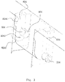
- Receptacle 81 is provided with a concave portion 810 having two opposing guiding sidewalls 811 and an open side 812.One of the guiding sidewalls 811 is provided with the first slot 814, and the other guiding sidewall 811 is provided with a second slot 824.
- Figure 1 shows a plurality of concave portion, these portions also referred to as receptacle of a second member (base) to be connected by a hinge system.
- the first slot and the second slot are provided on the two opposing guiding sidewalls in the same receptacle respectively.
- the two opposing guiding sidewalls of one receptacle are both provided with the first slots while the guiding sidewalls of other receptacles are all provided with the second slots.
- the two opposing guiding sidewalls of one receptacle are both provided with the second slots while the guiding sidewalls of other receptacles are all provided with the first slots.
- the first slot may be provided only on the one of the guiding sidewalls of one receptacle while another guiding sidewall of said receptacle and the guiding sidewalls of other receptacles are all provided with the second slots.
- the first slot and the second slot can be provided on either guiding sidewalls of either receptacles, as long as the first slot and the second slot are both exit on the hinge system of the present invention regardless of the amount of the first slots and the second slots.
- the first component (side wall) and the second component (base) connected to each other by the hinge system herein may be provided with a first pin and a second pin on the plug of the first component.
- the plug 31 has a projecting tongue portion 310, the first pin 314 and the second pin 324 being provided on opposite sides of the tongue portion 310, only one pin 314 being shown in the figure due to the projection angle.
- the tongue portion 310 of the plug 31 is inserted into the concave portion 810 of the receptacle 81, and the first pin 314 is inserted into the corresponding first slot 814.
- the first pin 314 may be moved or rotated in the first slot 814, and the tongue portion 310 can be turned and out of the open side 812 of the concave portion 810 of the receptacle 81.
- the first slot 814 is a straight slot.
- the second pin 324 is inserted into the corresponding second slot 824, and the second pin 324 may be moved or rotated in the second slot 824.
- the second slot 824 is a shaped slot.
- the first pin 314 is located at the bottom of the tongue portion 310, and the second pin 324 is located at the upper portion of the tongue portion 310. As shown in the figure, the position of the first pin 314 is lower than the position of the second pin 324.
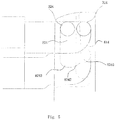
- FIG. 2 shows a shape of the second slot 824.
- the second slot 8241 has a notch 8241, a bottom 8242, a front sidewall and a rear sidewall, the front sidewall and the rear sidewall being two opposing walls.
- the notch is an opening end, a width expanded portion 8244 being provided on the first sidewall near the notch 8241, the width of the second slot 824 becoming larger at the width expanded portion so that a blocking shoulder is formed.
- the second sidewall is formed with an arc recess 8245 near the bottom 8242.
- the arc recess 8245 and the bottom 8242 are connected by an arc, also the bottom 8242 and the first sidewall are connected by an arc segment.
- the above mentioned hinges are mounted between the side wall 3 and the base 8, so that the side wall 3 can be rotated relative to the base 8.
- Figure 1 shows that two first hinges and two second hinges are mounted between the side wall 3 and the base 8, for example.
- the at least two tongue portions and at least two concave portions may be regarded as one tongue portion and one concave portion configured to be provided with the above mentioned slots and pins.
- the side wall 3 is erect, the first pin 314 being located at the bottom of the first slot 814, the second pin 324 being located at the arc recess of the sidewall of the second slot 824.
- the arc recess 8245 prevents the second pin 324 from moving upward, so that the side wall 3 cannot move upward either.
- the arc recess 8245 allows the side wall to turn inwardly around the first pin 314 (i.e. turn towards the open side 812, 822 in Figure 1 ).
- the position of the first pin 314 is lower than the position of the second pin 324 and, in the initial state shown in Figure 3 , the first pin 314 contacts with the bottom of the first slot 814 so as to support the side wall 3, and the second pin 324 is located in the arc recess 8245 so as to mainly prevent the side wall from moving upward.
- the first pin 314 acts as the pivot shaft, thus the second pin 324 is rotated around the first pin and moves towards the bottom 8242 of the second slot 824.
- the second pin 324 When the side wall 3 has reached to a predetermined angle, for example 45 degrees with respect to the horizontal position, the second pin 324 contacts with the bottom 8242 of the second slot 824, thus when the side wall continues to rotate, i.e., the side wall is folded, the second pin 324 will act as the pivot shaft of the side wall 3 and force the first pin 314 to move upward in the first slot 814. Further, the first pin 314 is tangent to the sidewall of the first slot 814, and the movement of the first pin 314 along the first slot 814 will force the second pin 324 to move toward an arc transition corner 8243 at the bottom 8242 of the second slot824.
- a predetermined angle for example 45 degrees with respect to the horizontal position
- the second pin 324 When the second pin 324 reaches the arc transition corner 8243, there is no object over the second pin 324 and the first pin 314, thus the second pin 324 and the first pin 314 are not obstructed, such that the bottom of the side wall may be moved up vertically.
- the second pin 324 After moving a distance , as shown in Figure 5 , when the side wall 3 is rotated to a folded state, the second pin 324 reaches the width expanded portion 8244 (second dent), and the width expanded portion 8244 prevents the second pin 324 from moving, so that the side wall 3 does not rotate any more.
- the side wall 3 stays at a folded state and does not need to rotate upward, the width expanded portion 8244 being used to lock the connection between the side wall 3 and the base when folded.
- the distance between the respective pins 314, 324 of the two side wall 1, 3 (the side wall is connected to the base 8 using a same hinge) along the vertical direction is equal to the distance between the centers of the side walls 1, 3 along the vertical direction, thus the second slot 824 should allow the folded side wall 3 to move vertically by a distance which equal to the sum of the above distance and the diameter of the second pin 324, that is, the distance between the arc transition corner 8243 and the width expanded portion 8244 should be greater or equal to the sum of the above distance and the diameter of the second pin 324.
- the width of opening of the second slot 824 is slightly larger than the diameter of the second pin 324, thus when the side wall 3 is disassembled from the base 8, the side wall 3 is rotated by 45 degrees such that the second pin 324 is disengaged from the arc recess 8245 of the second slot 824 and the unlock the side wall 3 and the base 8 in vertical direction. Thereafter, the side wall 3 is moved upward, the second pin will leave the second slot 824 from the opening of the second slot 824. At the same time, the first pin 314 will also leave the first slot 814. Therefore, the side wall 3 is disconnected from the base 5. The effect is that the side wall 3 and the base 8 may be disassembled without the aid of any tools.
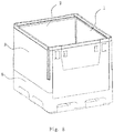
- a collapsible container such as a carton, comprises a base 8 in form of rectangular plate structure, wherein the foldable side walls 1,2,3,4 are coupled to the edges of the base 8 through the above hinge system respectively.
- the side walls 1, 2, 3, 4 When the side walls 1, 2, 3, 4 are erected, the side walls 1, 2, 3, 4 will be connected with each other through locking members.
- the principle of the above embodiment is that the horizontal distance between the two pins 314 and 324 is varied through rotating the side wall 3, such that the second pin will reach a limited position predetermined at the second slot. Therefore, the invention is not limited to the above embodiments.
- the first pin may be positioned at the first slot when the side walls are erected.
- Figures 9 and 10 show another embodiment according to the invention, it is similar to the above embodiment, thus those same structures are canceled.
- the first pin and the second pin are not located on a same line either.
- the second pin 324 located at a lower position will arrive at the pit of the second slot 824, so that the side wall 3 is prevented from moving upward by the pit (first pit).
- the second pin 324 is prevented from moving upward by the width expanded portion 8244 of the second slot 824.
- Figures 11 and 12 show another embodiment according to the invention, it is similar to the above embodiments, thus those same structures are canceled.
- the first pin and the second pin are not located on a same line either.
- the first pin 314 and the second pin 324 are located at a same height.
- the second pin 324 located at left side i.e. a side facing to the internal of the container
- the second pin 324 is prevented from moving up by the upper right pit of the second slot 824 (the second pin may be slightly moved).
- first pit and the second pit may be provided on different slots, such as the first pit is provided on the second slot, and the second is provided on the first slot.
- the first pin and the second pin may be cylindrical pins with same or different diameter.
- a plane may be formed on the cylindrical pin so as to contact with the pits, such that the movement of the pins is limited by the pits.
- the first pin and the second pin can be other pins with a variety of other shapes.
Landscapes
- Engineering & Computer Science (AREA)
- Mechanical Engineering (AREA)
- Rigid Containers With Two Or More Constituent Elements (AREA)
Claims (10)
- Scharniersystem, umfassend: einen ersten Stift (314) und einen zweiten Stift (324), die auf einer ersten Komponente (3) bereitgestellt sind; eine erste Nut (814) und eine zweite Nut (824), die jeweils in zwei Seiten eines konkaven Teils (810) einer zweiten Komponente (8) bereitgestellt sind; wobei der konkave Teil (810) mit einer geöffneten Seite (8i2) gebildet ist und die zweite Nut (824) mit einer ersten Vertiefung (8245), wobei eine zweite Vertiefung (8244) an der ersten Nut (814) oder der zweiten Vertiefung (8244) bereitgestellt ist;
der erste Stift (314) und der zweite Stift (324) nicht auf derselben Achse liegen, wobei der erste Stift (314) bewegbar in der ersten Nut (814) angeordnet ist, der zweite Stift (324) bewegbar in der zweiten Nut (824) angeordnet ist;
die erste Komponente (3) wahlweise zwischen einem ersten Positionszustand und einem zweiten Positionszustand relativ zu der zweiten Komponente (8) umschaltet; wenn die erste Komponente (3) in dem ersten Positionszustand bleibt, die erste Komponente (3) in die zweite Komponente (8) eingesetzt ist, der zweite Stift (324) durch die erste Nut (8245) aufgenommen wird, um den zweiten Stift (324) daran zu hindern, sich gegen ein öffnendes Ende (8241) der zweiten Nut (824) zu bewegen; der erste Stift (314) als eine Schwenkachse der Rotation der ersten Komponente (3) bezüglich der zweiten Komponente (8) wirkt; wenn die erste Komponente (3) in dem zweiten Positionszustand bleibt, im Vergleich zu dem ersten Positionszustand, die erste Komponente (3) um einen vordefinierten Winkel von der offenen Seite (812) rotiert wird, während sie sich in Richtung des öffnenden Endes (8241) der ersten Nut (814) oder der zweiten Nut (824) über eine vordefinierte Distanz bewegt, dann der erste Stift (314) oder der zweite Stift (324) durch die zweite Vertiefung (8244) aufgenommen wird, so dass die Bewegung des ersten Stifts (314) oder des zweiten Stifts (324) zu dem öffnenden Ende (8241) der ersten Nut (814) oder der zweiten Nut (824) durch die zweite Vertiefung (8244) begrenzt ist. - Scharniersystem nach Anspruch 1, wobei die erste Komponente (3) bezüglich der zweiten Komponente (8) im ersten Positionszustand errichtet ist, die erste Komponente (3) auf der zweiten Komponente (8) im zweiten Positionszustand überlagert; der erste Stift (314) und der zweite Stift (324) zylindrische Stifte mit demselben Durchmesser sind.
- Scharniersystem nach Anspruch 1, wobei der erste Stift (314) als eine drehbare Achse der ersten Komponente (3) dient nachdem die erste Komponente (3) von dem ersten Positionszustand umschaltet.
- Scharniersystem nach Anspruch 1, wobei die zweite Nut (824) eine geformte Nut ist; die erste Vertiefung (8245) eine auf der Rückseite der zweiten Nut (824) angeordnete Vertiefung ist; die zweite Vertiefung (8244) ein ausgeweiteter Teil an der Vorderseite der zweiten Nut (824) ist; und die Position des ausgeweiteten Teils (8244) näher an dem öffnenden Ende (8241) der zweiten Nut (824) liegt, als die Position der ersten Vertiefung (8245); die erste Nut (814) eine gerade Nut ist; die Position des ersten Stifts (314) tiefer liegt als die Position des zweiten Stifts (324), wenn die erste Komponente (3) in dem ersten Positionszustand bleibt, wobei, wenn die erste Komponente (3) in dem zweiten Positionszustand bleibt, die Position des ersten Stifts (314) und die Position des zweiten Stifts (324) von gleicher Höhe sind.
- Scharniersystem nach Anspruch 1, wobei die zweite Nut (824) eine geformte Nut ist; die erste Vertiefung eine Vertiefung ist, die an der Vorderseite der zweiten Nut (824) angeordnet ist; die zweite Vertiefung ein erweiterter Teil an der Rückseite der zweiten Nut (824) ist und die Position des erweiterten Teils näher an dem öffnenden Ende (8241) der zweiten Nut liegt als die Position der ersten Vertiefung; die erste Nut (814) eine gerade Nut ist; die Position des ersten Stifts (314) höher liegt als die Position des zweiten Stifts (324), wenn die erste Komponente (3) in dem ersten Positionszustand bleibt, wobei, wenn die erste Komponente (3) in dem zweiten Positionszustand bleibt, die Position des ersten Stifts (314) und die Position des zweiten Stifts (324) von gleicher Höhe sind.
- Scharniersystem nach Anspruch 1, wobei die zweite Nut (824) eine geformte Nut ist, die erste Vertiefung eine Vertiefung ist, die an der Vorderseite der zweiten Nut (824) angeordnet ist, der zweite Stift ein erweiterter Teil an der Rückseite der zweiten Nut (824) ist und die Position des erweiterten Teils näher an dem öffnenden Ende (8241) der zweiten Nut (824) liegt als die Position der ersten Vertiefung; die erste Nut (814) eine gerade Nut ist; die Position des ersten Stifts (314) und die Position des zweiten Stifts (324) von gleicher Höhe sind, wenn die erste Komponente (3) in dem ersten Positionszustand bleibt, wobei die Position des ersten Stifts (314) höher liegt als die Position des zweiten Stifts (324), wenn die erste Komponente (3) in dem zweiten Positionszustand bleibt.
- Scharniersystem nach Anspruch 1, wobei die erste Vertiefung und die zweite Vertiefung auf einer gleichen Seite oder auf einer gegenüberliegenden Seite gebildet sind.
- Scharniersystem nach Anspruch 1, wobei die erste Vertiefung auf der ersten Nut (814) gebildet ist und die erste Vertiefung und die zweite Vertiefung jeweils auf einer gleichen Seite oder gegenüberliegenden Seiten der ersten Nut (814) und der zweiten Nut (824) gebildet sind.
- Faltbarer Behälter umfasst eine Basis (8) und mehrere Seitenwände (1, 2, 3), die auf der Basis (8) montiert sind, wobei zumindest eine Seitenwand (1, 2, 3) über das Scharniersystem entsprechend einem der Ansprüche 1 bis 8 verbunden ist, wobei die erste Komponente (3) eine Seitenwand ist und die zweite Komponente (8) die Basis ist.
- Faltbarer Behälter nach Anspruch 9, wobei zwei gegenüberliegende Seitenwände (1, 2, 3) jeweils durch das Scharniersystem mit der Basis (8) verbunden sind.
Applications Claiming Priority (2)
| Application Number | Priority Date | Filing Date | Title |
|---|---|---|---|
| CN2011102954858A CN102502124B (zh) | 2011-09-29 | 2011-09-29 | 铰链系统以及可折叠容器 |
| PCT/CN2012/078369 WO2013044664A1 (zh) | 2011-09-29 | 2012-07-09 | 铰链系统以及可折叠容器 |
Publications (3)
| Publication Number | Publication Date |
|---|---|
| EP2765095A1 EP2765095A1 (de) | 2014-08-13 |
| EP2765095A4 EP2765095A4 (de) | 2015-06-03 |
| EP2765095B1 true EP2765095B1 (de) | 2016-12-07 |
Family
ID=46214277
Family Applications (1)
| Application Number | Title | Priority Date | Filing Date |
|---|---|---|---|
| EP12836349.6A Active EP2765095B1 (de) | 2011-09-29 | 2012-07-09 | Scharniersystem und faltbarer behälter |
Country Status (4)
| Country | Link |
|---|---|
| US (1) | US9327870B2 (de) |
| EP (1) | EP2765095B1 (de) |
| CN (1) | CN102502124B (de) |
| WO (1) | WO2013044664A1 (de) |
Families Citing this family (18)
| Publication number | Priority date | Publication date | Assignee | Title |
|---|---|---|---|---|
| CN102502124B (zh) | 2011-09-29 | 2013-07-24 | 上海鸿润科技有限公司 | 铰链系统以及可折叠容器 |
| CN102758572B (zh) | 2012-08-07 | 2015-08-26 | 上海鸿研物流技术有限公司 | 铰链固定结构和隐藏式铰链及容器 |
| CN103693264B (zh) | 2013-10-22 | 2016-08-17 | 上海鸿研物流技术有限公司 | 一种可折叠式容器 |
| US9161619B1 (en) * | 2014-10-07 | 2015-10-20 | Scott R. Somers | Configurable bottle storage rack and kit |
| CN104554980B (zh) | 2014-12-16 | 2016-09-14 | 上海鸿研物流技术有限公司 | 可折叠式容器 |
| CN104944012B (zh) * | 2015-05-07 | 2018-02-23 | 上海鸿研物流技术有限公司 | 可折叠容器 |
| CN105438594B (zh) * | 2015-11-20 | 2018-07-10 | 上海鸿研物流技术有限公司 | 框架及托盘围板箱 |
| CN106358399B (zh) * | 2016-08-31 | 2019-03-15 | 昆山一邦泰汽车零部件制造有限公司 | 一种用于机器人控制柜的柜门壳体机构 |
| US10065763B2 (en) | 2016-09-15 | 2018-09-04 | Arena Packaging, Llc | Wall latching system |
| CN108860932B (zh) * | 2017-05-16 | 2024-07-30 | 中国国际海运集装箱(集团)股份有限公司 | 托盘箱 |
| US10954033B2 (en) | 2017-09-29 | 2021-03-23 | Mtd Products Inc | Foldable crate for a lawn maintenance vehicle |
| CN109835570B (zh) * | 2019-02-27 | 2024-02-27 | 上海鸿研物流技术有限公司 | 可折叠容器 |
| CN110356725A (zh) * | 2019-07-31 | 2019-10-22 | 上海新意达塑料托盘有限公司 | 一种侧板铰接结构及大型容器 |
| US11926448B2 (en) | 2020-02-24 | 2024-03-12 | Joel Karsten | Container devices, systems, and methods |
| CN111846515B (zh) * | 2020-08-03 | 2024-06-04 | 上海鸿研物流技术有限公司 | 折叠容器 |
| CN112938090A (zh) * | 2021-03-01 | 2021-06-11 | 上海箱箱智能科技有限公司 | 可折叠容器 |
| US11084623B1 (en) * | 2021-03-23 | 2021-08-10 | David Ankele | Trackable nylon pallet and collapsible container |
| CN115384898A (zh) * | 2022-09-28 | 2022-11-25 | 上海箱箱智能科技有限公司 | 一种可折叠容器 |
Family Cites Families (14)
| Publication number | Priority date | Publication date | Assignee | Title |
|---|---|---|---|---|
| AT665U1 (de) * | 1995-04-20 | 1996-03-25 | Josef Haidlmair Maschinen Werk | Transport- und/oder lagerbehälter aus kunststoff |
| WO1996040564A1 (en) | 1995-06-07 | 1996-12-19 | Ropak Corporation | Collapsible container with hinged sidewalls |
| US6152317A (en) | 1998-01-26 | 2000-11-28 | Delta Consolidated Industries | Double-walled blow-molded article with insertable handle and method for making same |
| CA2352281A1 (en) * | 1998-11-25 | 2000-06-02 | Bent Kofod | Collapsible container for transporting a liquid |
| SE520413C2 (sv) * | 2001-09-19 | 2003-07-08 | Arca Systems Ab | Bulkcontainer |
| US7331480B1 (en) | 2002-09-27 | 2008-02-19 | Roger Nolan | Articulated hinge apparatus and related methods |
| US7100786B2 (en) | 2003-03-21 | 2006-09-05 | Rehrig Pacific Company | Collapsible container |
| SE527901C2 (sv) | 2004-04-26 | 2006-07-04 | Arca Systems Internat Ab | Behållare med löstagbara sidoväggar samt användning av en sektion av behållaren |
| JP4002260B2 (ja) * | 2004-09-22 | 2007-10-31 | 三菱樹脂株式会社 | 折り畳みコンテナ |
| JP4008455B2 (ja) | 2005-04-25 | 2007-11-14 | 三菱樹脂株式会社 | 折り畳みコンテナ |
| CN101117171A (zh) | 2006-08-01 | 2008-02-06 | 中国国际海运集装箱(集团)股份有限公司 | 折叠箱用铰链 |
| DE102009005212A1 (de) | 2009-01-20 | 2010-07-22 | Schoeller Arca Systems Gmbh | Behälter für Transport und Lagerung von Gütern mit einem Behälterboden und zumindest zwei übereinander klappbaren Seitenwänden |
| CN202368860U (zh) * | 2011-09-29 | 2012-08-08 | 上海鸿润科技有限公司 | 铰链系统以及可折叠容器 |
| CN102502124B (zh) | 2011-09-29 | 2013-07-24 | 上海鸿润科技有限公司 | 铰链系统以及可折叠容器 |
-
2011
- 2011-09-29 CN CN2011102954858A patent/CN102502124B/zh active Active
-
2012
- 2012-07-09 EP EP12836349.6A patent/EP2765095B1/de active Active
- 2012-07-09 US US14/348,386 patent/US9327870B2/en active Active
- 2012-07-09 WO PCT/CN2012/078369 patent/WO2013044664A1/zh not_active Ceased
Also Published As
| Publication number | Publication date |
|---|---|
| US9327870B2 (en) | 2016-05-03 |
| WO2013044664A1 (zh) | 2013-04-04 |
| EP2765095A1 (de) | 2014-08-13 |
| US20140231425A1 (en) | 2014-08-21 |
| EP2765095A4 (de) | 2015-06-03 |
| CN102502124B (zh) | 2013-07-24 |
| CN102502124A (zh) | 2012-06-20 |
Similar Documents
| Publication | Publication Date | Title |
|---|---|---|
| EP2765095B1 (de) | Scharniersystem und faltbarer behälter | |
| EP3061708B1 (de) | Zusammenklappbarer behälter | |
| CA2797455C (en) | Container with side walls foldable on top of one another | |
| CA2985214C (en) | Foldable container | |
| CN109835570B (zh) | 可折叠容器 | |
| EP3378796B1 (de) | Rahmen und palettenbehälter | |
| GB2446969A (en) | Stackable Collapsible container | |
| AU2010238513A1 (en) | Box with foldable side walls and locking mechanism with overload protection | |
| CA2771527C (en) | Foldable transport and storage container | |
| CN201281057Y (zh) | 一种锁具和使用该锁具的托盘箱 | |
| JP6468870B2 (ja) | 容器 | |
| CN108128563B (zh) | 货物用集装箱 | |
| JP2019099175A (ja) | 折畳み容器 | |
| CN220786479U (zh) | 折叠式储藏箱 | |
| JP2015058961A (ja) | 折り畳み箱 | |
| KR101250957B1 (ko) | 접철식 상자의 커버 구조 | |
| JP7636779B2 (ja) | 扉付き運搬用容器 | |
| CN217919186U (zh) | 一种全折叠式料框 | |
| JP2019094101A (ja) | 折畳み容器 | |
| JP2003160131A (ja) | 折り畳みコンテナー | |
| IL289873A (en) | Folding box | |
| JP2023045222A (ja) | 運搬用容器 | |
| JP2002154537A (ja) | 折り畳みコンテナー |
Legal Events
| Date | Code | Title | Description |
|---|---|---|---|
| PUAI | Public reference made under article 153(3) epc to a published international application that has entered the european phase |
Free format text: ORIGINAL CODE: 0009012 |
|
| 17P | Request for examination filed |
Effective date: 20140409 |
|
| AK | Designated contracting states |
Kind code of ref document: A1 Designated state(s): AL AT BE BG CH CY CZ DE DK EE ES FI FR GB GR HR HU IE IS IT LI LT LU LV MC MK MT NL NO PL PT RO RS SE SI SK SM TR |
|
| DAX | Request for extension of the european patent (deleted) | ||
| RA4 | Supplementary search report drawn up and despatched (corrected) |
Effective date: 20150504 |
|
| RIC1 | Information provided on ipc code assigned before grant |
Ipc: B65D 19/06 20060101ALI20150424BHEP Ipc: B65D 88/52 20060101ALN20150424BHEP Ipc: B65D 6/22 20060101AFI20150424BHEP |
|
| REG | Reference to a national code |
Ref country code: DE Ref legal event code: R079 Ref document number: 602012026415 Country of ref document: DE Free format text: PREVIOUS MAIN CLASS: B65D0088520000 Ipc: B65D0006220000 |
|
| GRAP | Despatch of communication of intention to grant a patent |
Free format text: ORIGINAL CODE: EPIDOSNIGR1 |
|
| RIC1 | Information provided on ipc code assigned before grant |
Ipc: B65D 6/22 20060101AFI20160519BHEP Ipc: B65D 88/52 20060101ALN20160519BHEP Ipc: B65D 19/06 20060101ALI20160519BHEP |
|
| INTG | Intention to grant announced |
Effective date: 20160615 |
|
| GRAS | Grant fee paid |
Free format text: ORIGINAL CODE: EPIDOSNIGR3 |
|
| GRAA | (expected) grant |
Free format text: ORIGINAL CODE: 0009210 |
|
| AK | Designated contracting states |
Kind code of ref document: B1 Designated state(s): AL AT BE BG CH CY CZ DE DK EE ES FI FR GB GR HR HU IE IS IT LI LT LU LV MC MK MT NL NO PL PT RO RS SE SI SK SM TR |
|
| REG | Reference to a national code |
Ref country code: GB Ref legal event code: FG4D |
|
| REG | Reference to a national code |
Ref country code: CH Ref legal event code: EP Ref country code: AT Ref legal event code: REF Ref document number: 851462 Country of ref document: AT Kind code of ref document: T Effective date: 20161215 |
|
| REG | Reference to a national code |
Ref country code: IE Ref legal event code: FG4D |
|
| REG | Reference to a national code |
Ref country code: DE Ref legal event code: R096 Ref document number: 602012026415 Country of ref document: DE |
|
| PG25 | Lapsed in a contracting state [announced via postgrant information from national office to epo] |
Ref country code: LV Free format text: LAPSE BECAUSE OF FAILURE TO SUBMIT A TRANSLATION OF THE DESCRIPTION OR TO PAY THE FEE WITHIN THE PRESCRIBED TIME-LIMIT Effective date: 20161207 |
|
| REG | Reference to a national code |
Ref country code: LT Ref legal event code: MG4D |
|
| REG | Reference to a national code |
Ref country code: NL Ref legal event code: MP Effective date: 20161207 |
|
| PG25 | Lapsed in a contracting state [announced via postgrant information from national office to epo] |
Ref country code: LT Free format text: LAPSE BECAUSE OF FAILURE TO SUBMIT A TRANSLATION OF THE DESCRIPTION OR TO PAY THE FEE WITHIN THE PRESCRIBED TIME-LIMIT Effective date: 20161207 Ref country code: NO Free format text: LAPSE BECAUSE OF FAILURE TO SUBMIT A TRANSLATION OF THE DESCRIPTION OR TO PAY THE FEE WITHIN THE PRESCRIBED TIME-LIMIT Effective date: 20170307 Ref country code: GR Free format text: LAPSE BECAUSE OF FAILURE TO SUBMIT A TRANSLATION OF THE DESCRIPTION OR TO PAY THE FEE WITHIN THE PRESCRIBED TIME-LIMIT Effective date: 20170308 Ref country code: SE Free format text: LAPSE BECAUSE OF FAILURE TO SUBMIT A TRANSLATION OF THE DESCRIPTION OR TO PAY THE FEE WITHIN THE PRESCRIBED TIME-LIMIT Effective date: 20161207 |
|
| REG | Reference to a national code |
Ref country code: AT Ref legal event code: MK05 Ref document number: 851462 Country of ref document: AT Kind code of ref document: T Effective date: 20161207 |
|
| PG25 | Lapsed in a contracting state [announced via postgrant information from national office to epo] |
Ref country code: ES Free format text: LAPSE BECAUSE OF FAILURE TO SUBMIT A TRANSLATION OF THE DESCRIPTION OR TO PAY THE FEE WITHIN THE PRESCRIBED TIME-LIMIT Effective date: 20161207 Ref country code: HR Free format text: LAPSE BECAUSE OF FAILURE TO SUBMIT A TRANSLATION OF THE DESCRIPTION OR TO PAY THE FEE WITHIN THE PRESCRIBED TIME-LIMIT Effective date: 20161207 Ref country code: RS Free format text: LAPSE BECAUSE OF FAILURE TO SUBMIT A TRANSLATION OF THE DESCRIPTION OR TO PAY THE FEE WITHIN THE PRESCRIBED TIME-LIMIT Effective date: 20161207 Ref country code: FI Free format text: LAPSE BECAUSE OF FAILURE TO SUBMIT A TRANSLATION OF THE DESCRIPTION OR TO PAY THE FEE WITHIN THE PRESCRIBED TIME-LIMIT Effective date: 20161207 |
|
| PG25 | Lapsed in a contracting state [announced via postgrant information from national office to epo] |
Ref country code: NL Free format text: LAPSE BECAUSE OF FAILURE TO SUBMIT A TRANSLATION OF THE DESCRIPTION OR TO PAY THE FEE WITHIN THE PRESCRIBED TIME-LIMIT Effective date: 20161207 |
|
| REG | Reference to a national code |
Ref country code: FR Ref legal event code: PLFP Year of fee payment: 6 |
|
| PG25 | Lapsed in a contracting state [announced via postgrant information from national office to epo] |
Ref country code: RO Free format text: LAPSE BECAUSE OF FAILURE TO SUBMIT A TRANSLATION OF THE DESCRIPTION OR TO PAY THE FEE WITHIN THE PRESCRIBED TIME-LIMIT Effective date: 20161207 Ref country code: IS Free format text: LAPSE BECAUSE OF FAILURE TO SUBMIT A TRANSLATION OF THE DESCRIPTION OR TO PAY THE FEE WITHIN THE PRESCRIBED TIME-LIMIT Effective date: 20170407 Ref country code: SK Free format text: LAPSE BECAUSE OF FAILURE TO SUBMIT A TRANSLATION OF THE DESCRIPTION OR TO PAY THE FEE WITHIN THE PRESCRIBED TIME-LIMIT Effective date: 20161207 Ref country code: CZ Free format text: LAPSE BECAUSE OF FAILURE TO SUBMIT A TRANSLATION OF THE DESCRIPTION OR TO PAY THE FEE WITHIN THE PRESCRIBED TIME-LIMIT Effective date: 20161207 Ref country code: EE Free format text: LAPSE BECAUSE OF FAILURE TO SUBMIT A TRANSLATION OF THE DESCRIPTION OR TO PAY THE FEE WITHIN THE PRESCRIBED TIME-LIMIT Effective date: 20161207 |
|
| PG25 | Lapsed in a contracting state [announced via postgrant information from national office to epo] |
Ref country code: BE Free format text: LAPSE BECAUSE OF FAILURE TO SUBMIT A TRANSLATION OF THE DESCRIPTION OR TO PAY THE FEE WITHIN THE PRESCRIBED TIME-LIMIT Effective date: 20161207 Ref country code: PL Free format text: LAPSE BECAUSE OF FAILURE TO SUBMIT A TRANSLATION OF THE DESCRIPTION OR TO PAY THE FEE WITHIN THE PRESCRIBED TIME-LIMIT Effective date: 20161207 Ref country code: IT Free format text: LAPSE BECAUSE OF FAILURE TO SUBMIT A TRANSLATION OF THE DESCRIPTION OR TO PAY THE FEE WITHIN THE PRESCRIBED TIME-LIMIT Effective date: 20161207 Ref country code: BG Free format text: LAPSE BECAUSE OF FAILURE TO SUBMIT A TRANSLATION OF THE DESCRIPTION OR TO PAY THE FEE WITHIN THE PRESCRIBED TIME-LIMIT Effective date: 20170307 Ref country code: PT Free format text: LAPSE BECAUSE OF FAILURE TO SUBMIT A TRANSLATION OF THE DESCRIPTION OR TO PAY THE FEE WITHIN THE PRESCRIBED TIME-LIMIT Effective date: 20170407 Ref country code: SM Free format text: LAPSE BECAUSE OF FAILURE TO SUBMIT A TRANSLATION OF THE DESCRIPTION OR TO PAY THE FEE WITHIN THE PRESCRIBED TIME-LIMIT Effective date: 20161207 Ref country code: AT Free format text: LAPSE BECAUSE OF FAILURE TO SUBMIT A TRANSLATION OF THE DESCRIPTION OR TO PAY THE FEE WITHIN THE PRESCRIBED TIME-LIMIT Effective date: 20161207 |
|
| REG | Reference to a national code |
Ref country code: DE Ref legal event code: R097 Ref document number: 602012026415 Country of ref document: DE |
|
| PLBE | No opposition filed within time limit |
Free format text: ORIGINAL CODE: 0009261 |
|
| STAA | Information on the status of an ep patent application or granted ep patent |
Free format text: STATUS: NO OPPOSITION FILED WITHIN TIME LIMIT |
|
| 26N | No opposition filed |
Effective date: 20170908 |
|
| PG25 | Lapsed in a contracting state [announced via postgrant information from national office to epo] |
Ref country code: DK Free format text: LAPSE BECAUSE OF FAILURE TO SUBMIT A TRANSLATION OF THE DESCRIPTION OR TO PAY THE FEE WITHIN THE PRESCRIBED TIME-LIMIT Effective date: 20161207 Ref country code: SI Free format text: LAPSE BECAUSE OF FAILURE TO SUBMIT A TRANSLATION OF THE DESCRIPTION OR TO PAY THE FEE WITHIN THE PRESCRIBED TIME-LIMIT Effective date: 20161207 |
|
| REG | Reference to a national code |
Ref country code: CH Ref legal event code: PL |
|
| REG | Reference to a national code |
Ref country code: IE Ref legal event code: MM4A |
|
| PG25 | Lapsed in a contracting state [announced via postgrant information from national office to epo] |
Ref country code: CH Free format text: LAPSE BECAUSE OF NON-PAYMENT OF DUE FEES Effective date: 20170731 Ref country code: IE Free format text: LAPSE BECAUSE OF NON-PAYMENT OF DUE FEES Effective date: 20170709 Ref country code: LI Free format text: LAPSE BECAUSE OF NON-PAYMENT OF DUE FEES Effective date: 20170731 |
|
| PG25 | Lapsed in a contracting state [announced via postgrant information from national office to epo] |
Ref country code: LU Free format text: LAPSE BECAUSE OF NON-PAYMENT OF DUE FEES Effective date: 20170709 |
|
| REG | Reference to a national code |
Ref country code: FR Ref legal event code: PLFP Year of fee payment: 7 |
|
| PG25 | Lapsed in a contracting state [announced via postgrant information from national office to epo] |
Ref country code: MT Free format text: LAPSE BECAUSE OF NON-PAYMENT OF DUE FEES Effective date: 20170709 |
|
| PG25 | Lapsed in a contracting state [announced via postgrant information from national office to epo] |
Ref country code: HU Free format text: LAPSE BECAUSE OF FAILURE TO SUBMIT A TRANSLATION OF THE DESCRIPTION OR TO PAY THE FEE WITHIN THE PRESCRIBED TIME-LIMIT; INVALID AB INITIO Effective date: 20120709 Ref country code: MC Free format text: LAPSE BECAUSE OF FAILURE TO SUBMIT A TRANSLATION OF THE DESCRIPTION OR TO PAY THE FEE WITHIN THE PRESCRIBED TIME-LIMIT Effective date: 20161207 |
|
| PG25 | Lapsed in a contracting state [announced via postgrant information from national office to epo] |
Ref country code: CY Free format text: LAPSE BECAUSE OF FAILURE TO SUBMIT A TRANSLATION OF THE DESCRIPTION OR TO PAY THE FEE WITHIN THE PRESCRIBED TIME-LIMIT Effective date: 20161207 |
|
| PG25 | Lapsed in a contracting state [announced via postgrant information from national office to epo] |
Ref country code: MK Free format text: LAPSE BECAUSE OF FAILURE TO SUBMIT A TRANSLATION OF THE DESCRIPTION OR TO PAY THE FEE WITHIN THE PRESCRIBED TIME-LIMIT Effective date: 20161207 |
|
| PG25 | Lapsed in a contracting state [announced via postgrant information from national office to epo] |
Ref country code: TR Free format text: LAPSE BECAUSE OF FAILURE TO SUBMIT A TRANSLATION OF THE DESCRIPTION OR TO PAY THE FEE WITHIN THE PRESCRIBED TIME-LIMIT Effective date: 20161207 |
|
| PG25 | Lapsed in a contracting state [announced via postgrant information from national office to epo] |
Ref country code: AL Free format text: LAPSE BECAUSE OF FAILURE TO SUBMIT A TRANSLATION OF THE DESCRIPTION OR TO PAY THE FEE WITHIN THE PRESCRIBED TIME-LIMIT Effective date: 20161207 |
|
| PGFP | Annual fee paid to national office [announced via postgrant information from national office to epo] |
Ref country code: DE Payment date: 20250722 Year of fee payment: 14 |
|
| PGFP | Annual fee paid to national office [announced via postgrant information from national office to epo] |
Ref country code: GB Payment date: 20250722 Year of fee payment: 14 |
|
| PGFP | Annual fee paid to national office [announced via postgrant information from national office to epo] |
Ref country code: FR Payment date: 20250725 Year of fee payment: 14 |