EP2762193B1 - Ensemble cathéter - Google Patents
Ensemble cathéter Download PDFInfo
- Publication number
- EP2762193B1 EP2762193B1 EP12835725.8A EP12835725A EP2762193B1 EP 2762193 B1 EP2762193 B1 EP 2762193B1 EP 12835725 A EP12835725 A EP 12835725A EP 2762193 B1 EP2762193 B1 EP 2762193B1
- Authority
- EP
- European Patent Office
- Prior art keywords
- proximal end
- outer needle
- distal end
- plug
- catheter assembly
- Prior art date
- Legal status (The legal status is an assumption and is not a legal conclusion. Google has not performed a legal analysis and makes no representation as to the accuracy of the status listed.)
- Active
Links
- 230000000903 blocking effect Effects 0.000 claims description 32
- 238000003780 insertion Methods 0.000 claims description 32
- 230000037431 insertion Effects 0.000 claims description 32
- 239000012528 membrane Substances 0.000 claims description 32
- 238000007789 sealing Methods 0.000 claims description 17
- 239000012530 fluid Substances 0.000 claims description 14
- 239000012466 permeate Substances 0.000 claims description 10
- 230000000149 penetrating effect Effects 0.000 claims description 5
- 230000023597 hemostasis Effects 0.000 description 73
- 239000008280 blood Substances 0.000 description 33
- 210000004369 blood Anatomy 0.000 description 33
- 230000002439 hemostatic effect Effects 0.000 description 22
- 239000000463 material Substances 0.000 description 17
- 230000000052 comparative effect Effects 0.000 description 13
- 210000003462 vein Anatomy 0.000 description 10
- 229920005989 resin Polymers 0.000 description 8
- 239000011347 resin Substances 0.000 description 8
- 210000004204 blood vessel Anatomy 0.000 description 7
- 238000004891 communication Methods 0.000 description 7
- 238000006073 displacement reaction Methods 0.000 description 5
- 230000017531 blood circulation Effects 0.000 description 4
- 230000004927 fusion Effects 0.000 description 4
- -1 polytetrafluoroethylene Polymers 0.000 description 4
- 239000004698 Polyethylene Substances 0.000 description 3
- 230000036772 blood pressure Effects 0.000 description 3
- 229920003049 isoprene rubber Polymers 0.000 description 3
- 239000000203 mixture Substances 0.000 description 3
- 229920001200 poly(ethylene-vinyl acetate) Polymers 0.000 description 3
- 229920002647 polyamide Polymers 0.000 description 3
- 229920000728 polyester Polymers 0.000 description 3
- 230000001012 protector Effects 0.000 description 3
- 239000004952 Polyamide Substances 0.000 description 2
- 239000005062 Polybutadiene Substances 0.000 description 2
- 239000004743 Polypropylene Substances 0.000 description 2
- PPBRXRYQALVLMV-UHFFFAOYSA-N Styrene Chemical compound C=CC1=CC=CC=C1 PPBRXRYQALVLMV-UHFFFAOYSA-N 0.000 description 2
- 239000000853 adhesive Substances 0.000 description 2
- 230000001070 adhesive effect Effects 0.000 description 2
- TZCXTZWJZNENPQ-UHFFFAOYSA-L barium sulfate Chemical compound [Ba+2].[O-]S([O-])(=O)=O TZCXTZWJZNENPQ-UHFFFAOYSA-L 0.000 description 2
- 230000000694 effects Effects 0.000 description 2
- 229920000840 ethylene tetrafluoroethylene copolymer Polymers 0.000 description 2
- 239000005038 ethylene vinyl acetate Substances 0.000 description 2
- 238000000034 method Methods 0.000 description 2
- 229920002857 polybutadiene Polymers 0.000 description 2
- 229920000573 polyethylene Polymers 0.000 description 2
- 229920005672 polyolefin resin Polymers 0.000 description 2
- 229920001343 polytetrafluoroethylene Polymers 0.000 description 2
- 239000004810 polytetrafluoroethylene Substances 0.000 description 2
- 229920002635 polyurethane Polymers 0.000 description 2
- 239000004814 polyurethane Substances 0.000 description 2
- 239000011148 porous material Substances 0.000 description 2
- 238000003825 pressing Methods 0.000 description 2
- 229910000838 Al alloy Inorganic materials 0.000 description 1
- JOYRKODLDBILNP-UHFFFAOYSA-N Ethyl urethane Chemical compound CCOC(N)=O JOYRKODLDBILNP-UHFFFAOYSA-N 0.000 description 1
- 244000043261 Hevea brasiliensis Species 0.000 description 1
- 229920000459 Nitrile rubber Polymers 0.000 description 1
- 239000004677 Nylon Substances 0.000 description 1
- 229920001774 Perfluoroether Polymers 0.000 description 1
- 239000004721 Polyphenylene oxide Substances 0.000 description 1
- 229910001069 Ti alloy Inorganic materials 0.000 description 1
- RTAQQCXQSZGOHL-UHFFFAOYSA-N Titanium Chemical compound [Ti] RTAQQCXQSZGOHL-UHFFFAOYSA-N 0.000 description 1
- 229920006311 Urethane elastomer Polymers 0.000 description 1
- 229920000800 acrylic rubber Polymers 0.000 description 1
- 239000002390 adhesive tape Substances 0.000 description 1
- 150000001336 alkenes Chemical class 0.000 description 1
- 229910052782 aluminium Inorganic materials 0.000 description 1
- XAGFODPZIPBFFR-UHFFFAOYSA-N aluminium Chemical compound [Al] XAGFODPZIPBFFR-UHFFFAOYSA-N 0.000 description 1
- AYJRCSIUFZENHW-DEQYMQKBSA-L barium(2+);oxomethanediolate Chemical compound [Ba+2].[O-][14C]([O-])=O AYJRCSIUFZENHW-DEQYMQKBSA-L 0.000 description 1
- 229940036348 bismuth carbonate Drugs 0.000 description 1
- 229920005549 butyl rubber Polymers 0.000 description 1
- 230000006835 compression Effects 0.000 description 1
- 238000007906 compression Methods 0.000 description 1
- 239000002872 contrast media Substances 0.000 description 1
- 230000003247 decreasing effect Effects 0.000 description 1
- 230000006866 deterioration Effects 0.000 description 1
- GMZOPRQQINFLPQ-UHFFFAOYSA-H dibismuth;tricarbonate Chemical compound [Bi+3].[Bi+3].[O-]C([O-])=O.[O-]C([O-])=O.[O-]C([O-])=O GMZOPRQQINFLPQ-UHFFFAOYSA-H 0.000 description 1
- 239000003814 drug Substances 0.000 description 1
- 229920001971 elastomer Polymers 0.000 description 1
- 229920001973 fluoroelastomer Polymers 0.000 description 1
- 238000003384 imaging method Methods 0.000 description 1
- 239000007788 liquid Substances 0.000 description 1
- 238000004519 manufacturing process Methods 0.000 description 1
- 229910052751 metal Inorganic materials 0.000 description 1
- 239000002184 metal Substances 0.000 description 1
- 239000007769 metal material Substances 0.000 description 1
- 229920003052 natural elastomer Polymers 0.000 description 1
- 229920001194 natural rubber Polymers 0.000 description 1
- 229920001778 nylon Polymers 0.000 description 1
- JRZJOMJEPLMPRA-UHFFFAOYSA-N olefin Natural products CCCCCCCC=C JRZJOMJEPLMPRA-UHFFFAOYSA-N 0.000 description 1
- 230000035515 penetration Effects 0.000 description 1
- 229920000058 polyacrylate Polymers 0.000 description 1
- 229920000515 polycarbonate Polymers 0.000 description 1
- 239000004417 polycarbonate Substances 0.000 description 1
- 229920000570 polyether Polymers 0.000 description 1
- 229920000098 polyolefin Polymers 0.000 description 1
- 229920001155 polypropylene Polymers 0.000 description 1
- 229920005606 polypropylene copolymer Polymers 0.000 description 1
- 229920000915 polyvinyl chloride Polymers 0.000 description 1
- 239000004800 polyvinyl chloride Substances 0.000 description 1
- 239000000047 product Substances 0.000 description 1
- 239000005060 rubber Substances 0.000 description 1
- 229920002379 silicone rubber Polymers 0.000 description 1
- 239000004945 silicone rubber Substances 0.000 description 1
- 239000010935 stainless steel Substances 0.000 description 1
- 229910001220 stainless steel Inorganic materials 0.000 description 1
- 229920003048 styrene butadiene rubber Polymers 0.000 description 1
- 229920002725 thermoplastic elastomer Polymers 0.000 description 1
- 239000010936 titanium Substances 0.000 description 1
- 229910052719 titanium Inorganic materials 0.000 description 1
- 239000012780 transparent material Substances 0.000 description 1
- CMPGARWFYBADJI-UHFFFAOYSA-L tungstic acid Chemical compound O[W](O)(=O)=O CMPGARWFYBADJI-UHFFFAOYSA-L 0.000 description 1
- 239000004636 vulcanized rubber Substances 0.000 description 1
Images


Classifications
-
- A—HUMAN NECESSITIES
- A61—MEDICAL OR VETERINARY SCIENCE; HYGIENE
- A61M—DEVICES FOR INTRODUCING MEDIA INTO, OR ONTO, THE BODY; DEVICES FOR TRANSDUCING BODY MEDIA OR FOR TAKING MEDIA FROM THE BODY; DEVICES FOR PRODUCING OR ENDING SLEEP OR STUPOR
- A61M25/00—Catheters; Hollow probes
- A61M25/0067—Catheters; Hollow probes characterised by the distal end, e.g. tips
- A61M25/0074—Dynamic characteristics of the catheter tip, e.g. openable, closable, expandable or deformable
- A61M25/0075—Valve means
-
- A—HUMAN NECESSITIES
- A61—MEDICAL OR VETERINARY SCIENCE; HYGIENE
- A61M—DEVICES FOR INTRODUCING MEDIA INTO, OR ONTO, THE BODY; DEVICES FOR TRANSDUCING BODY MEDIA OR FOR TAKING MEDIA FROM THE BODY; DEVICES FOR PRODUCING OR ENDING SLEEP OR STUPOR
- A61M25/00—Catheters; Hollow probes
- A61M25/01—Introducing, guiding, advancing, emplacing or holding catheters
- A61M25/06—Body-piercing guide needles or the like
- A61M25/0606—"Over-the-needle" catheter assemblies, e.g. I.V. catheters
-
- A—HUMAN NECESSITIES
- A61—MEDICAL OR VETERINARY SCIENCE; HYGIENE
- A61M—DEVICES FOR INTRODUCING MEDIA INTO, OR ONTO, THE BODY; DEVICES FOR TRANSDUCING BODY MEDIA OR FOR TAKING MEDIA FROM THE BODY; DEVICES FOR PRODUCING OR ENDING SLEEP OR STUPOR
- A61M25/00—Catheters; Hollow probes
- A61M25/0067—Catheters; Hollow probes characterised by the distal end, e.g. tips
- A61M25/0082—Catheter tip comprising a tool
- A61M25/0084—Catheter tip comprising a tool being one or more injection needles
-
- A—HUMAN NECESSITIES
- A61—MEDICAL OR VETERINARY SCIENCE; HYGIENE
- A61M—DEVICES FOR INTRODUCING MEDIA INTO, OR ONTO, THE BODY; DEVICES FOR TRANSDUCING BODY MEDIA OR FOR TAKING MEDIA FROM THE BODY; DEVICES FOR PRODUCING OR ENDING SLEEP OR STUPOR
- A61M39/00—Tubes, tube connectors, tube couplings, valves, access sites or the like, specially adapted for medical use
- A61M39/02—Access sites
- A61M39/06—Haemostasis valves, i.e. gaskets sealing around a needle, catheter or the like, closing on removal thereof
- A61M2039/0633—Haemostasis valves, i.e. gaskets sealing around a needle, catheter or the like, closing on removal thereof the seal being a passive seal made of a resilient material with or without an opening
- A61M2039/064—Slit-valve
-
- A—HUMAN NECESSITIES
- A61—MEDICAL OR VETERINARY SCIENCE; HYGIENE
- A61M—DEVICES FOR INTRODUCING MEDIA INTO, OR ONTO, THE BODY; DEVICES FOR TRANSDUCING BODY MEDIA OR FOR TAKING MEDIA FROM THE BODY; DEVICES FOR PRODUCING OR ENDING SLEEP OR STUPOR
- A61M39/00—Tubes, tube connectors, tube couplings, valves, access sites or the like, specially adapted for medical use
- A61M39/02—Access sites
- A61M39/06—Haemostasis valves, i.e. gaskets sealing around a needle, catheter or the like, closing on removal thereof
- A61M2039/0633—Haemostasis valves, i.e. gaskets sealing around a needle, catheter or the like, closing on removal thereof the seal being a passive seal made of a resilient material with or without an opening
- A61M2039/0653—Perforated disc
Definitions
- the present invention relates to, for example, a catheter assembly which dwells in a blood vessel or on a skin of a patient, allowing transfusion to the patient.
- an indwelling needle is pierced (inserted) in a blood vessel of a patient so as to dwell.
- the distal end portion of a transfusion tube and the proximal end portion of the indwelling needle exposed on the skin are connected to provide communication with the transfusion tube. Therefore, the indwelling needle is configured as a catheter assembly so as that the connection with the transfusion tube can rapidly be carried out and the connected portion can easily be allowed to dwell on the skin of the patient (e.g., see the specification of US 2010/0204648 A ).
- the catheter assembly disclosed in the specification of US 2010/0204648 A includes a tubular outer needle (catheter), an outer needle hub which is connected to the proximal end portion of the outer needle, an inner needle having a sharp needle tip on the distal end, and an inner needle hub which is connected to the proximal end portion of the inner needle. Further, in the inside of the outer needle hub, a valve mechanism configured with a hemostasis valve which prevents outflow of blood and a plug (pusher) which penetrates a slit of the hemostasis valve is provided.
- the outer needle and the inner needle are integrally pierced in the blood vessel, and then the inner needle is solely pulled out so as to allow the outer needle to dwell in the blood vessel.
- the blood flows into a passage in the outer needle hub in the proximal end side via the outer needle.
- the hemostasis valve contained in the outer needle hub prevents the outflow of the blood.
- the plug is inserted in an opening/closing part of the hemostasis valve and the transfusion tube is connected to the proximal end side of the outer needle hub, thereby allowing the transfusion line to communicate all the way with the blood vessel of the patient.
- valve mechanism of the catheter assembly As described above, it is desirable to precisely stop the blood flowing in via the outer needle, as well as to allow the connection of the catheter assembly and the transfusion tube to be carried out easily and surely. That is, it is required to to simultaneously satisfy both hemostatic of blood and penetrability of the plug when inserted in the hemostasis valve (including easiness, rapidity, or reliability).
- the slit of the hemostasis valve is configured not to open easily which makes it difficult to insert the plug, reducing penetrability.
- the opening/closing part of the hemostasis valve is configured to open easily so as to allow the plug to be inserted easily, reducing hemostatic. That is, it is difficult to simultaneously satisfy both hemostatic and penetrability of the valve mechanism of the catheter assembly.
- the present invention is made in view of the problem mentioned above.
- the object of the present invention is to provide a catheter assembly which can improve hemostatic and penetrability of the valve mechanism by a simple configuration, thereby reducing the outflow of blood from the valve mechanism as well as improving the efficiency of connecting operation of the transfusion tube.
- the present invention provides the catheter assembly including a tubular insertion portion, a support portion which is connected to the proximal end side of the insertion portion and has therein a flow passage communicating with the inside of the insertion portion, a valve body which is provided in the flow passage and has a blocking membrane stopping the flow of fluid and an opening/closing part allowing the blocking membrane to partially open or close, and an insertion member which is provided closer to the proximal end than the blocking membrane and is inserted in the opening/closing part by moving toward the distal end.
- the catheter assembly is characterized in that the opening/closing part is formed in a single slit shape penetrating the blocking membrane, and is formed to have a relation of L f ⁇ L r , where L f is a linear length at the distal end opening from which the insertion member protrudes and L r is a linear length at the proximal end opening in which the insertion member is inserted.
- the opening/closing part of the hemostasis valve is formed in a single slit shape penetrating the blocking membrane, and is formed to have the relation of L f ⁇ L r , where L f is a linear length at the distal end opening from which the insertion member protrudes and L r is a linear length at the proximal end opening in which the insertion member is inserted. So that when the insertion member is not inserted in the opening/closing part, the opening/closing part can surely be closed since the linear length L f at the distal end opening is short, thereby preventing blood from flowing out from the valve body to the proximal end side.
- the insertion member When the insertion member is inserted in the opening/closing part, the insertion member can easily enter into the opening/closing part from the proximal end opening since the linear length L rat the proximal end opening is long. That is, as for the catheter assembly, the hemostatic of blood and the penetrability of the plug are simultaneously improved so that the outflow of blood of the patient can drastically be reduced and further the efficiency of connecting operation of the transfusion tube can be improved.
- the opening/closing part is formed in an isosceles trapezoid shape in which the distal end opening and the proximal end opening are the upper base and the lower base of the isosceles trapezoid shape, respectively, in a side cross sectional view of the valve body.
- the insertion member inserted from the proximal end opening of the opening/closing part is squeezed by uniform contacting force from both legs of the trapezoid shape and can advance smoothly toward the distal end opening of the opening/closing part, so that the penetrability of the insertion member is further improved.
- a sealing member which the gas can permeate but the fluid can hardly permeate may preferably be arranged so as to block the flow passage.
- the sealing member which the gas can penetrate but the fluid can hardly permeate the air existing in the flow passage can be exhausted to the proximal end side, and further, the fluid (blood) which flows into the flow passage can be prevented from flowing out to the proximal end side.
- an inner needle which is inserted in the insertion portion, and an inner needle hub which is fixed to the proximal end portion of the inner needle and can be connected to the proximal end side of the support portion may be included.
- the insertion portion and the inner needle can easily be pierced by gripping and operating the inner needle hub.
- the hemostatic and penetrability of the valve mechanism configured with the valve body and the insertion member can be improved so that the outflow of blood from the valve mechanism is reduced, thereby improving the efficiency of connecting operation of the transfusion tube.
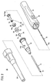
- Fig. 1 is an overall perspective view illustrating a catheter assembly 10 according to the embodiment.
- Fig. 2 is an exploded perspective view of the catheter assembly 10 in Fig. 1 .
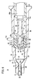
- Fig. 3 is a side cross sectional view of the catheter assembly 10 in Fig. 1 . Note that, in the description below, the left side in the drawing will be referred to as a distal end (forward) and the right side in the drawing will be referred to as a proximal end (rearward), based on the illustration of the catheter assembly 10 in Fig. 1 .
- the catheter assembly 10 includes a tubular outer needle 12 (insertion portion), an outer needle hub 14 (support portion) connected to the proximal end portion of the outer needle 12, an inner needle 16 having a sharp needle tip 16a on the distal end, and an inner needle hub 18 connected to the proximal end portion of the inner needle 16.
- the catheter assembly 10 pierces a vein (blood vessel) of a patient with the outer needle 12 attached together with the inner needle 16 (the outer needle 12 covering the periphery of the inner needle 16), and then the inner needle 16 is evulsed together with the inner needle hub 18.
- a protector 20 (see Fig. 2 ) is attached to prevent carelessly piercing with the outer needle 12 and the inner needle 16.
- the outer needle 12 of the catheter assembly 10 is configured as a flexible tubular (cylindrical) member (catheter).
- a resin particularly, a soft resin material is preferable.
- a fluororesin such as polytetrafluoroethylene (PTFE), ethylene-tetrafluoroethylene copolymer (ETFE), perfluoroalkoxy fluororesin (PFA), an olefin resin such as polyethylene and polypropylene or a mixture thereof, polyurethane, polyester, polyamide, polyether nylon resin, and a mixture of the olefin resin and ethylene-vinyl acetate copolymer may be used.
- PTFE polytetrafluoroethylene
- ETFE ethylene-tetrafluoroethylene copolymer
- PFA perfluoroalkoxy fluororesin
- an olefin resin such as polyethylene and polypropylene or a mixture thereof, polyurethane, polyester, polyamide, polyether nylon resin, and
- the outer needle 12 may preferably be composed of a transparent resin so that the whole, or a portion of, the inside of the outer needle 12 can be seen. For this, when the outer needle 12 is inserted and dwelled in the vein, the blood flowing into the outer needle hub 14 through a lumen 22 (see Fig. 3 ) of the outer needle 12 (also named as "flashback”) can visually be checked.
- an imaging function can be provided.
- an X-ray contrast medium for example, barium sulfate, barium carbonate, bismuth carbonate, tungstic acid
- the proximal end portion of the outer needle 12 is fluid-tightly fixed to the distal end portion of the outer needle hub 14 by a method, for example, caulking, fusion (heat-fusion, high-frequency fusion, or the like), and adhesion with an adhesive.
- a method for example, caulking, fusion (heat-fusion, high-frequency fusion, or the like), and adhesion with an adhesive.
- the outer needle 12 is fixed to and supported by the outer needle hub 14 using a caulk pin 24 (also see Fig. 3 and Fig. 4 ).
- the outer needle hub 14 is formed with a resin material harder than the outer needle 12 and is formed in a cylindrical shape which becomes thinner toward the distal end.
- the outer needle hub 14 fixes and supports the proximal end portion of the outer needle 12 so as to make the operation (piercing) of the outer needle 12 easy and to allow the outer needle 12 to easily communicate with the transfusion tube.
- the outer needle hub 14 includes a tab 14a which protrudes outward and is provided on the outer circumferential surface of the middle portion in the axial direction. With the tab 14a, the manual advancing (piercing) of the outer needle 12 in the vein can easily be carried out.
- the lumen of the outer needle hub 14 functions as a flow passage 26 which allows the transfusion to flow therein.
- the flow passage 26 opens at the proximal end surface of the outer needle hub 14 and is connected to (communicates with) the lumen 22 of the outer needle 12 which is fixed to the distal end portion of the outer needle hub 14.
- the flow passage 26 of the outer needle hub 14 includes an outer needle connection part 28, a distal end guiding part 30, a valve body arrangement part 32, and a connector connection part 34 in this order from the distal end side to the proximal end side (see Fig. 3 ).
- the outer needle connection part 28 includes a wall portion 36 (inner diameter) which is approximately identical to the outer diameter of the outer needle 12 at the distal end portion of the outer needle hub 14. The proximal end portion of the outer needle 12 is inserted in the outer needle connection part 28.
- the distal end guiding part 30 is continuously connected, at the distal end side thereof, to the outer needle connection part 28, and thereby functions to guide the transfusion supplied from the proximal end side to the outer needle 12.
- the wall portion 38 constituting the distal end guiding part 30 has a tapered surface 38a of which inner diameter close to the distal end gradually increases toward the proximal end. From the middle portion which is continuously connected to the tapered surface 38a to the proximal end, the wall portion 38 is formed in an approximately parallel shape.
- the valve body arrangement part 32 is continuously connected, at the distal end side thereof, to the distal end guiding part 30 and is configured with a wall portion 40 having a larger diameter than that of the wall portion 38 of the distal end guiding part 30. Therefore, a stepped portion is formed between the distal end guiding part 30 and the valve body arrangement part 32.
- a hemostasis valve 46 and a sealing member 48 which will be described below are arranged in the valve body arrangement part 32.
- the connector connection part 34 is continuously connected, at the distal end side thereof, to the valve body arrangement part 32 and extends toward the proximal end.
- the connector connection part 34 allows a connector 44 (see Fig. 6 and Fig. 7 ) of the transfusion tube to engage therein.
- the wall portion 42 constituting the connector connection part 34 is formed in a shape parallel to the axial direction.
- the wall portion 42 of the connector connection part 34 may have a tapered shape in which the inner diameter of the wall portion 42 gradually increases toward the proximal end.
- the distal end portion of the connector 44 in a corresponding tapered shape (tapered angle), the distal end portion of the connector 44 can easily be inserted in the proximal end side of the connector connection part 34 so as to be connected. With the connection made in such manner, the tightness of contact between the wall portion 42 of the connector connection part 34 and the outer circumferential surface of the connector 44 increases, providing connection having higher fluid-tightness.
- Fig. 4 is a partial side cross sectional view illustrating a state in which an inner needle 16 and an inner needle hub 18 is pulled out from the catheter assembly 10 in Fig. 3 .
- Fig. 5 is a cross sectional view taken along the line V-V in Fig. 4 .
- a caulk pin 24 in the flow passage 26 of the outer needle hub 14, a caulk pin 24, a hemostasis valve 46 (valve body), a sealing member 48, and a plug 50 (insertion member) are contained in this order from the distal end side.
- the hemostasis valve 46 and the plug 50 function as a valve mechanism 45 which can stop the blood and supply the transfusion to the catheter assembly 10.
- the caulk pin 24 is a member for connecting and fixing the outer needle 12 and the outer needle hub 14.
- the caulk pin 24 includes a tubular cylindrical portion 52 in the distal end side and a tapered portion 54 of which diameter gradually increases from the cylindrical portion 52 toward the proximal end side.
- the cylindrical portion 52 of the caulk pin 24 is contained in the outer needle connection part 28 of the outer needle hub 14 (flow passage 26), and the tapered portion 54 of the caulk pin 24 is contained in the distal end side of the distal end guiding part 30 of the outer needle hub 14.
- the cylindrical portion 52 is formed so as that the outer diameter is approximately identical to the lumen 22 of the outer needle 12, and extends in the axial direction by a predetermined length.
- the cylindrical portion 52 is inserted and caulked in the outer needle connection part 28 with the outer needle 12 inserted in the outer needle connection part 28 of the outer needle hub 14.
- the wall portion 36 of the outer needle connection part 28 and the cylindrical portion 52 of the caulk pin 24 surroundingly holds the outer needle 12 so as the outer needle 12 to be fixingly held in the outer needle hub 14.
- the caulk pin 24 may preferably be formed with a metal or a hard resin to caulk the outer needle 12 and the outer needle hub 14 with the cylindrical portion 52.
- the tapered portion 54 of the caulk pin 24 is formed so as that the outer diameter gradually increases from the distal end side toward the proximal end side, corresponding to the tapered surface 38a of the distal end guiding part 30 of the outer needle hub 14. Therefore, the caulk pin 24 is contained in the flow passage 26 with the tapered portion 54 and the tapered surface 38a in a tight contact. When transfusion flows in from the proximal end side, the tapered portion 54 allows the transfusion to smoothly flow out toward the outer needle 12.
- the hemostasis valve 46 is a member arranged so as to block the flow passage 26 of the outer needle hub 14 and has a function of blocking the outflow of the fluid (blood).
- the hemostasis valve 46 is formed in a bottomed cylindrical shape and arranged so as that a side circumferential wall 56 is in tight contact with the wall portion 40 of the valve body arrangement part 32 of the outer needle hub 14.
- the bottom portion of the hemostasis valve 46 is configured as a blocking membrane 58 which blocks the flow of the transfusion.
- a slit 60 (opening/closing part) is formed in the middle portion of the blocking membrane 58 so as to penetrate the blocking membrane 58.
- the blocking membrane 58 has a predetermined membrane thickness and functions as a valve receiving blood flowing into the flow passage 26. That is, the blocking membrane 58 is configured to have predetermined flexibility so as that the slit 60 will not open easily and let the blood flow into the proximal end side of the hemostasis valve 46.
- the slit 60 is formed so as to penetrate the blocking membrane 58 as a single line, in a front view, and to exist as a single plane shape.
- the slit 60 is configured so that the inner needle 16 and the plug 50 can be inserted and removed therethrough.
- the slit 60 is formed to close by itself when the inner needle 16 and the plug 50 is not inserted.
- the slit 60 is formed in an isosceles trapezoid shape in which openings on both sides of the blocking membrane 58 (the distal end opening 62 and the proximal end opening 64) are the bases (the upper base and the lower base) when viewed from a side surface cross sectional view (see Fig. 4 ).
- the slit 60 has a relation of L f ⁇ L r , where L f is a linear length at the distal end opening 62 and L r is a linear length at the proximal end opening 64. That is, the slit 60 has a shape in which the distance between the legs of the trapezoid shape gradually increases from the distal end opening 62 toward the proximal end opening 64.
- the specific configuration and effect of the slit 60 will be described in detail below.
- the hemostasis valve 46 is preferably composed of a flexible material having a hardness which prevents the slit 60 to open easily by a blood flow (blood pressure). By composing the hemostasis valve 46 with a flexible material, the plug 50 can easily be inserted through the slit 60.
- a rubber material such as natural rubber, isoprene rubber, butyl rubber, butadiene rubber, styrene-butadiene rubber, urethane rubber, nitrile rubber, acrylic rubber, fluororubber, and silicone rubber, a thermoplastic elastomer such as urethane-based, polyester-based, polyamide-based, olefin-based, and styrene-based, or a mixture thereof may be used.
- isoprene rubber is preferably used.
- a plurality of inner circumferential grooves 66 which provides communication between the distal end guiding part 30 of the outer needle hub 14 and the proximal end side of the valve body arrangement part 32 is provided.
- the inner circumferential groove 66 is formed so as that the distal end portion of the inner circumferential groove 66 cuts into the stepped portion between the distal end guiding part 30 and the valve body arrangement part 32.
- the inner circumferential groove 66 is extendingly provided, in the axial direction, from the distal end portion along the wall portion 40 of the valve body arrangement part 32.
- the inner circumferential groove 66 is provided to prevent gas (air) from remaining in the distal end guiding part 30 of the outer needle hub 14 after piercing the outer needle 12 and the inner needle 16 into the vein of the patient followed by evulsion of the inner needle 16. That is, the gas existing closer to the distal end than the hemostasis valve 46 is introduced to the proximal end side, after the inner needle 16 is evulsed, pushed by the blood flowing into the flow passage 26, thereby passing through the inner circumferential groove 66.
- the inner circumferential groove 66 is formed on the wall portion 40 of the outer needle hub 14 from the distal end side to the proximal end side not only in a linear shape.
- the inner circumferential groove 66 may be formed in, for example, a wave-shape or a spiral-shape. Further, the depth of the inner circumferential groove 66 depends on the shape of the outer needle hub 14 and the hemostasis valve 46. However, it is preferable to provide a depth of, for example, about 5 to 20 ⁇ m. Further, the inner circumferential groove 66 may be formed not only on the wall portion 40 (inner circumferential surface) of the outer needle hub 14 but on the side circumferential wall 56 of the hemostasis valve 46.
- the catheter assembly 10 is provided with the sealing member 48 in the proximal end side of the hemostasis valve 46 so as to block the inner circumferential groove 66.
- the sealing member 48 is formed in a cylindrical shape and has sealability allowing gas to permeate but fluid not to permeate.
- the sealing member 48 is arranged so as to contact tightly with the hemostasis valve 46 and to block the inner circumferential groove 66.
- the distal end portion of the sealing member 48 is formed in a cylindrical protruding portion 48a which engages in the proximal end side opening of the hemostasis valve 46.
- the sealing member 48 can be fixed to the wall portion 40 of the outer needle hub 14 (valve body arrangement part 32) by a method such as fusion or adhesion.
- the displacement of the distal end side and the proximal end side of the hemostasis valve 46 and the sealing member 48 are restricted by the valve body arrangement part 32 of the outer needle hub 14. Therefore, even when the inner needle 16 or the plug 50 is removed, the arranged location of the hemostasis valve 46 is maintained, thereby providing smooth opening/closing operation of the slit 60.
- the sealing member 48 which allows gas to permeate but fluid hard to permeate is used.
- a sealing member formed with, for example, a porous material such as a sintered material made of polyethylene can preferably be used.
- a sealing member 48 of a porous material is also preferable in that it is easy to produce and can be produced with high accuracy.
- the plug 50 which constitutes the valve mechanism 45 together with the hemostasis valve 46 is formed in an approximately cylindrical shape with a hard resin material.
- the plug 50 is arranged closer to the proximal end than the blocking membrane 58 in the flow passage 26 of the outer needle hub 14 and configured to advance freely in the axial direction of the outer needle hub 14.
- the lumen 68 of the plug 50 functions as a flow passage which allows transfusion to pass therethrough.
- the plug 50 advances toward the distal end of the outer needle hub 14 by a predetermined operation (pushing operation of the connector 44 made when the transfusion tube is connected) and is inserted in the slit 60 of the hemostasis valve 46, thereby providing communication between the distal end guiding part 30 (flow passage 26) of the outer needle hub 14 and the lumen 68.
- the plug 50 is formed to have a distal end expanding portion 70, a body portion 72, and a proximal end expanding portion 74, from the distal end side, in this order.
- the distal end expanding portion 70 is a member which penetrates the hemostasis valve 46 (slit 60) and is arranged in the distal end guiding part 30 of the outer needle hub 14, along with the advancement of the plug 50.
- two brims protruding outward along the radial direction and extending along the circumferential direction are arrayed in the axial direction.
- the second brim 70b functions as an engagement portion which engages with the slit 60 of the hemostasis valve 46 with the plug 50 penetrating (inserted in) the slit 60. That is, by the second brim 70b of the plug 50 engaging with the slit 60 of the hemostasis valve 46, unintentional movement of the plug 50 toward the proximal end is prevented, so that the flow passage 26 of the outer needle hub 14 is surely kept in communication with the lumen 68 of the plug 50.
- first and second brims 70a and 70b are formed in a tapered shape in which the diameter gradually increases from the distal end toward the proximal end. Being formed in the tapered shape as described above, when the plug 50 penetrates the slit 60 of the hemostasis valve 46, the first brim 70a and the second brim 70b surely press the slit 60 outward one after another, allowing the penetration easy to be carried out.
- the body portion 72 of the plug 50 is continuously connected to the distal end expanding portion 70 and extends toward the proximal end at a predetermined length.
- the body portion 72 is arranged through the valve body arrangement part 32 and the connector connection part 34.
- the proximal end expanding portion 74 is continuously connected to the proximal end side of the body portion 72 so that the proximal end expanding portion 74 is arranged in the connector connection part 34 of the outer needle hub 14.
- a flange 74a extending outward along the radial direction and extending along the circumferential direction is formed.
- the flange 74a is formed to have an outer diameter approximately identical to the wall portion 42 (inner diameter) of the connector connection part 34 of the outer needle hub 14. Therefore, when the plug 50 advances, the flange 74a slides against the wall portion 42 of the connector connection part 34, and thereby the movement is stably carried out.
- the plug 50 Before the plug 50 advances, the plug 50 exists closer to the proximal end than the slit 60 so that the slit 60 closes by itself, thereby blocking the flow passage 26. And when the plug 50 advances, the distal end expanding portion 70 penetrates the slit 60 to move toward the distal end side farther than the hemostasis valve 46, thereby connecting the lumen 68 of the plug 50 and the flow passage 26. That is, the catheter assembly 10 provides communication between the flow passage 26 and the lumen 68 of the plug 50 by advancing the plug 50 along the axial direction of the flow passage 26 so as to insert the distal end expanding portion 70 in the slit 60 of the hemostasis valve 46 (see Fig. 7 ).
- the proximal end portion of the inner needle 16 of the catheter assembly 10 is fixed to the inner needle hub 18, and is formed to have a length allowing the inner needle 16 to penetrate the outer needle 12 and the outer needle hub 14 from the proximal end portion toward the distal end portion.
- the inner needle 16 is inserted through the outer needle 12, the outer needle hub 14, the hemostasis valve 46, and the plug 50.
- a sharp needle tip 16a of the inner needle 16 is configured to protrude from the distal end opening of the outer needle 12, thereby allowing the needle tip 16a to easily pierce the surface of a living body.
- a metal material for example, a stainless steel, aluminum or an aluminum alloy, or titanium or a titanium alloy may be used.
- a groove not illustrated in the drawing may be provided along the axial direction of the inner needle 16.
- the groove can function as an introducing passage which introduces blood to the lumen 22 of the outer needle 12 when the outer needle 12 and the inner needle 16 are pierced in a blood vessel.
- the blood introduced to the groove flows into a space between the outer needle 12 and the inner needle 16. In this manner, a flashback of the blood can surely be checked at an earlier timing.
- the inner needle hub 18 includes a case 76 by which the inner needle 16 can be operated from the proximal end side. Inside the case 76, a fixing block 78 which fixes and holds the inner needle 16 is provided. The case 76 is formed in a thin long shape which is easy to grip by a hand. Further, the inner needle hub 18 can be connected to the proximal end side of the outer needle hub 14. In this manner, the piercing of the outer needle 12 and the inner needle 16 can easily be carried out by operating the inner needle hub 18.
- the outer needle 12 and the inner needle 16 are pierced in the vein of the patient, and then, the operation of pulling out (evulsing) the inner needle 16 inserted in the outer needle 12 is carried out.
- the user of the catheter assembly 10 can easily remove the inner needle 16 from the outer needle 12 by gripping and pulling the inner needle hub 18 (case 76) to pull out the inner needle 16.
- a resin material for example, polyolefin such as polyethylene, polypropylene, and ethylene-vinyl acetate copolymer, polyurethane, polyamide, polyester, polycarbonate, polybutadiene, polyvinyl chloride may be used. Further, by composing the plug 50 with the same material, production cost can be reduced.
- Fig. 6 is a partial side cross sectional view illustrating a state in which a plug 50 is advanced, not completely, in the catheter assembly 10 in Fig. 4 .
- Fig. 7 is a partial side cross sectional view illustrating a state in which a plug 50 is advanced so as to be inserted in a hemostasis valve 46 in the catheter assembly 10 in Fig. 6 .
- the cylindrical connector 44 is inserted in the connector connection part 34 of the outer needle hub 14 after evulsing the inner needle 16.
- the connector 44 is formed to have an outer diameter approximately identical to the wall portion 42 (inner diameter) of the connector connection part 34.
- the catheter assembly 10 is supplied with transfusion via the transfusion bag, the transfusion tube, and the connector 44, and can further introduce the transfusion to the flow passage 26 of the outer needle hub 14 and the lumen 22 of the outer needle 12 through the lumen 68 of the plug 50.
- a locking mechanism (not illustrated in the drawing) which keeps a connected state may preferably be provided to the outer needle hub 14 and the connector 44.
- the distal end portion of the connector 44 may be formed in a tapered shape in which the outer diameter of the distal end portion gradually increases toward the proximal end. In this manner, when connecting the connector 44, the connector 44 can easily be inserted in the proximal end side of the outer needle hub 14, and can easily be removed from the outer needle hub 14 after supplying transfusion.
- the plug 50 may be configured to have the inner diameter of the proximal end expanding portion 74 same as, or larger than, the inner diameter of the connector 44. In this manner, when the connector 44 is connected to the proximal end portion of the outer needle hub 14, the inflow of transfusion from the connector 44 into the plug 50 can easily and surely be provided.
- the catheter assembly 10 according to the embodiment is basically configured as described above. Now, the operation and effect, when the catheter assembly 10 is used, will be described.
- the catheter assembly 10 is provided, before used, with each of the components illustrated in Fig. 2 assembled. That is, as illustrated in Fig. 3 , the proximal end portion of the outer needle 12 is fixed to the outer needle hub 14 and the outer needle 12 protrudes toward the distal end. Each of the caulk pin 24, the hemostasis valve 46, the sealing member 48, and the plug 50 is arranged at each predetermined location in the inside (flow passage 26) of the outer needle hub 14. Further, the proximal end portion of the inner needle 16 is fixed to the inner needle hub 18. The inner needle 16 is inserted through the outer needle hub 14 and then through the lumen 22 of the outer needle 12. The needle tip 16a of the inner needle 16 exposes itself from the distal end portion of the outer needle 12.
- the inner needle 16 penetrates the slit 60 of the hemostasis valve 46 and the lumen 68 of the plug 50 to be connected to the inner needle hub 18. Further, the protector 20 (see Fig. 2 ) is attached to the catheter assembly 10 so as to cover, from the distal end of the outer needle hub 14, the outer needle 12 and the inner needle 16.
- the protector 20 is removed, and then, the catheter assembly 10 is positioned at a desired location (location in which piercing is carried out) on the patient. Then, the inner needle hub 18 is gripped to pierce the inner needle 16 and the outer needle 12 into the vein of the patient.
- the blood flows through the space between the outer needle 12 and the inner needle 16 toward the proximal end by the blood pressure. At this time, since the outer needle 12 or the outer needle hub 14 are formed with a transparent material, the inflow of the blood can be seen.
- the blood flowing into the outer needle hub 14 reaches the distal end guiding part 30 of the flow passage 26, and blocked by the hemostasis valve 46 to flow out further in the proximal end side.
- the air existing in the distal end guiding part 30 passes through the inner circumferential groove 66 and is exhausted to the proximal end side of the outer needle hub 14 via the sealing member 48 which allows gas to permeate therethrough.
- the catheter assembly 10 is further advanced toward the distal end by a slight distance. Specifically, by putting a finger on the tab 14a of the outer needle hub 14, the outer needle 12 and the inner needle 16 are advanced by a predetermined distance relative to the vein. After advancing the outer needle 12, by fixing the outer needle 12 or the outer needle hub 14 with a hand, gripping the inner needle hub 18 with another hand, and pulling the inner needle hub 18 toward the proximal end, the inner needle 16 is evulsed from the outer needle 12. In this manner, the catheter assembly 10 is in a state in which the outer needle 12 and the outer needle hub 14 dwells in the patient. Note that, the evulsed inner needle 16 is no longer necessary and is disposed.
- the slit 60 of the hemostasis valve 46 is closed when the inner needle 16 has been evulsed, so that the blood flowing into the flow passage 26 (distal end guiding part 30) is prevented from flowing outside (leaking) from the proximal end side of the outer needle hub 14.
- the hemostasis valve 46 has the linear length L f at the distal end opening 62 of the slit 60 (opening/closing part) formed in a single line shorter than the linear length L r at the proximal end opening 64. Therefore, even when pressing force (blood pressure) is applied from the blood flowing into the flow passage 26 of the outer needle hub 14, the blood is prevented from flowing out at the distal end opening 62 having shorter linear length L f . That is, the hemostasis valve 46 can surely stop (block) the blood by the blocking membrane 58.
- the linear length L f at the distal end opening 62 of the slit 60 depends on the size of the hemostasis valve 46 and the membrane thickness of the blocking membrane 58. However, for example, it is preferable to provide the linear length L f within a range of 0.3 to 0.6 mm. By providing the linear length L f within a range of 0.3 to 0.6 mm, sufficient hemostatic of blood can be obtained so that the outflow of blood can surely be prevented. Further, corresponding to the linear length L f at the distal end opening 62, the linear length L r at the proximal end opening 64 of the slit 60 may preferably be provided within a range of 0.4 to 0. 8 mm. That is, the linear length L r at the proximal end opening 64 may preferably be provided longer than the linear length L f at the distal end opening 62 by about 30% regarding relation of insertion property of the plug 50.
- the outer needle hub 14 is fixed on the skin of the patient by an adhesive tape or the like.
- the connector 44 of the transfusion tube is inserted from the proximal end side of the outer needle hub 14.
- the plug 50 contained in the flow passage 26 of the outer needle hub 14 moves toward the distal end pressed by the connector 44, and the distal end expanding portion 70 of the plug 50 pushes itself into the blocking membrane 58 of the hemostasis valve 46.
- the hemostasis valve 46 has the long linear length L r at the proximal end opening 64 of the slit 60 so that the plug 50 can be easily inserted in the slit 60. That is, when the distal end surface of the plug 50 (distal end expanding portion 70) presses, by making contact with, the proximal end surface of the blocking membrane 58 of the hemostasis valve 46, the blocking membrane 58 elastically deforms and the center portion of the blocking membrane 58 is displaced toward the distal end. The deformation of the blocking membrane 58 expands the proximal end opening 64, so that the distal end expanding portion 70 can easily enter into the slit 60.
- the plug 50 can be inserted through the slit 60 at a stage in which the pushed-in distance of the plug 50 (the volume of deformation of the blocking membrane 58) is small, thereby reducing the pressing force (insertion force) applied on the connection of the transfusion tube.
- the connecting operation of the transfusion tube can be carried out in a short time, further allowing the plug 50 to surely penetrate the hemostasis valve 46. Further, the load applied on the hemostasis valve 46 which is being elastically deformed is reduced.
- valve mechanism 45 improves penetrability during the insertion of the plug 50, and by the plug 50 being smoothly inserted in the hemostasis valve 46, the blood can be prevented from flowing out to the proximal end side of the blocking membrane 58. That is, the catheter assembly 10 also improves hemostatic during insertion of the plug 50.
- the second brim 70b When the plug 50 is inserted until the second brim 70b reaches the distal end opening 62 of the hemostasis valve 46, the second brim 70b is hooked on the rim of the slit 60, thereby preventing the plug 50 from coming off. In this manner, the communication between the flow passage 26 (distal end guiding part 30) of the outer needle hub 14 and the lumen 68 of the plug 50 is provided, thereby allowing the transfusion to be introduced from the transfusion tube to the outer needle 12.
- the supplying of transfusion from the transfusion bag starts.
- the transfusion which passes through the transfusion tube and then the connector 44 flows out from the opening of the distal end expanding portion 70 of the plug 50 to be filled in the entire flow passage 26. Further, the transfusion is introduced in the vein of the patient via the flow passage 26 of the outer needle hub 14 through the lumen 22 of the outer needle 12.
- the slit 60 of the hemostasis valve 46 is formed in a single slit shape penetrating the blocking membrane 58, and is formed to have the relation of L f ⁇ L r , where L f is a linear length at the distal end opening 62 from which the plug 50 protrudes and L r is a linear length at the proximal end opening 64 in which the plug 50 is inserted. So that when the plug 50 is not inserted in the slit 60, the slit 60 can surely be closed since the linear length L fat the distal end opening 62 is short, thereby preventing blood from flowing out to the proximal end side of the outer needle hub 14.
- the plug 50 when the plug 50 is inserted in the slit 60, the plug 50 can easily enter into the proximal end opening 64 since the linear length L rat the proximal end opening 64 is long. That is, as for the catheter assembly 10, the hemostatic of blood and the penetrability of the plug 50 are simultaneously improved so that the outflow of blood of the patient is drastically reduced and the efficiency of connecting operation of the transfusion tube is further improved.
- the slit 60 is formed in an isosceles trapezoid shape in which the distal end opening 62 and the proximal end opening 64 are the upper base and the lower base of the isosceles trapezoid shape, respectively, when viewed from a side cross sectional view of the hemostasis valve 46.
- the plug 50 inserted from the proximal end opening 64 of the slit 60 is squeezed by uniform contacting force from both legs of the trapezoid shape and can advance smoothly toward the distal end opening 62 of the slit 60, thereby further improving the penetrability of the plug 50.
- Fig. 8 is a table in which penetrability and hemostatic regarding a slit 60 of the hemostasis valve 46 according to the embodiment (example) and a slit of a hemostasis valve of comparative examples 1 to 4 are listed.
- the linear length L f at the distal end opening 62 is provided to be 0. 3 mm
- the linear length L r at the proximal end opening 64 is provided to be 0.4 mm.
- the linear length L f at the distal end opening and the linear length L r at the proximal end opening are provided to be the same value of 0.3 mm.
- the linear length Lf at the distal end opening and the linear length Lr at the proximal end opening are provided to be the same value of 0.4 mm.
- the linear length L f at the distal end opening is provided to be 0.4 mm
- the linear length L r at the proximal end opening is provided to be 0. 3 mm.
- a front view of the blocking membrane is illustrated.
- the hemostasis valve according to the comparative example 4 is formed to have a slit extending in three directions, evenly spaced between each other, from the center of the blocking membrane (forming a Y-shape).
- the pressure which the slit of the hemostasis valve receives from the fluid is measured as a standard to assess hemostatic.
- the pressure which is measured when the fluid is actually flowing out is compared.
- the deformation (distance by which the center portion moves toward the distal end: a stroke of the plug) of the hemostasis valve when the plug is inserted is measured as a standard to assess penetrability.
- the amount of displacement which is measured when the plug is actually inserted is compared.
- the hemostasis valve 46 of the example is able to receive a pressure of about 80 kPa from the fluid.
- the displacement of about 2.5 mm is measured as the stroke of the plug 50.
- hemostatic of blood is measured to be about the same level as the example, although the displacement of 3. 5 mm is measured as the stroke of the plug, resulting in reduction of penetrability of the plug.
- penetrability of the plug is measured to be about the same level as the example, although the pressure of about 60 kPa is received from the fluid, resulting in reduction of hemostatic.
- hemostatic is measured to be about the same level as the example, although the result shows that the penetrability of the plug decreased.
- the displacement of about 1.5 mm is measured as the stroke of the plug showing superiority in penetrability, although the pressure of about only 8 kPa is received from the fluid, resulting in drastic reduction in hemostatic.
- the result for the comparative examples 1 to 4 shows deterioration in either of penetrability and hemostatic, but on the contrary, the example shows good result regarding both penetrability and hemostatic.
Landscapes
- Health & Medical Sciences (AREA)
- Life Sciences & Earth Sciences (AREA)
- Biophysics (AREA)
- Pulmonology (AREA)
- Engineering & Computer Science (AREA)
- Anesthesiology (AREA)
- Biomedical Technology (AREA)
- Heart & Thoracic Surgery (AREA)
- Hematology (AREA)
- Animal Behavior & Ethology (AREA)
- General Health & Medical Sciences (AREA)
- Public Health (AREA)
- Veterinary Medicine (AREA)
- Infusion, Injection, And Reservoir Apparatuses (AREA)
- Media Introduction/Drainage Providing Device (AREA)
Claims (3)
- Ensemble de cathéter (10) comprenant :une partie d'insertion tubulaire (12) :caractérisé en ce queune partie de support (14) qui est reliée à un côté d'extrémité proximale de la partie d'insertion (12) et qui comporte un passage d'écoulement (26) communiquant avec l'intérieur de la partie d'insertion (12) ;un corps de soupape (46) qui est placé dans le passage d'écoulement (26) et comporte une membrane de blocage (58) qui bloque l'écoulement de fluide et une partie d'ouverture/fermeture (60) permettant à la membrane de blocage (58) de s'ouvrir ou de se fermer partiellement ; etun élément d'insertion (50) qui est placé plus près de l'extrémité proximale que la membrane de blocage (58) et est inséré dans la partie d'ouverture/fermeture (60) en se déplaçant vers l'extrémité distale, dans lequel la partie d'ouverture/fermeture (60) est formée sous une forme à fente unique pénétrant dans la membrane de blocage (58), et est formée de manière à avoir une relation Lf<Lr où Lf est une longueur linéaire au niveau d'une ouverture d'extrémité distale (62) à partir de laquelle fait saillie l'élément d'insertion (50), et Lr est une longueur linéaire au niveau d'une ouverture d'extrémité proximale (64) dans laquelle l'élément d'insertion (50) est inséré,
la partie d'ouverture/fermeture (60) est formée sous la forme d'un trapèze isocèle où l'ouverture d'extrémité distale (62) et l'ouverture d'extrémité proximale (64) sont une base supérieure et une base inférieure de la forme du trapèze isocèle, respectivement, quand on voit à partir d'une vue en coupe transversale latérale du corps de soupape (46). - Ensemble de cathéter (10) selon la revendication 1, dans lequel un élément d'étanchéité (48) à travers lequel un gaz peut passer mais un fluide peut difficilement passer est disposé dans un côté d'extrémité proximale du corps de soupape (46) de manière à bloquer le passage d'écoulement (26).
- Ensemble de cathéter (10) selon la revendication 1 ou 2, comprenant en outre :une aiguille intérieure (16) qui est insérée dans la partie d'insertion (12) ; etun embout d'aiguille intérieure (18) qui est fixé à une partie d'extrémité proximale de l'aiguille intérieure (16) et qui peut être relié à un côté d'extrémité proximale de la partie de support (14).
Applications Claiming Priority (2)
| Application Number | Priority Date | Filing Date | Title |
|---|---|---|---|
| JP2011212694 | 2011-09-28 | ||
| PCT/JP2012/073328 WO2013047205A1 (fr) | 2011-09-28 | 2012-09-12 | Ensemble cathéter |
Publications (3)
| Publication Number | Publication Date |
|---|---|
| EP2762193A1 EP2762193A1 (fr) | 2014-08-06 |
| EP2762193A4 EP2762193A4 (fr) | 2015-08-19 |
| EP2762193B1 true EP2762193B1 (fr) | 2016-10-26 |
Family
ID=47995239
Family Applications (1)
| Application Number | Title | Priority Date | Filing Date |
|---|---|---|---|
| EP12835725.8A Active EP2762193B1 (fr) | 2011-09-28 | 2012-09-12 | Ensemble cathéter |
Country Status (6)
| Country | Link |
|---|---|
| US (1) | US9095679B2 (fr) |
| EP (1) | EP2762193B1 (fr) |
| JP (1) | JP6067567B2 (fr) |
| CN (1) | CN103842021B (fr) |
| AU (1) | AU2012317947B2 (fr) |
| WO (1) | WO2013047205A1 (fr) |
Cited By (1)
| Publication number | Priority date | Publication date | Assignee | Title |
|---|---|---|---|---|
| DE102016106626A1 (de) * | 2016-04-11 | 2017-10-12 | Joline Gmbh & Co. Kg | Einführkatheter mit einem Ventilkörper |
Families Citing this family (23)
| Publication number | Priority date | Publication date | Assignee | Title |
|---|---|---|---|---|
| US10089443B2 (en) | 2012-05-15 | 2018-10-02 | Baxter International Inc. | Home medical device systems and methods for therapy prescription and tracking, servicing and inventory |
| US8323249B2 (en) | 2009-08-14 | 2012-12-04 | The Regents Of The University Of Michigan | Integrated vascular delivery system |
| WO2011146772A1 (fr) | 2010-05-19 | 2011-11-24 | Tangent Medical Technologies Llc | Système d'aiguille de sécurité utilisable avec dispositif médical |
| US8771230B2 (en) | 2010-05-19 | 2014-07-08 | Tangent Medical Technologies, Llc | Integrated vascular delivery system |
| JP6382210B2 (ja) | 2012-11-12 | 2018-08-29 | アイシーユー・メディカル・インコーポレーテッド | 医療用コネクタ |
| US9592367B2 (en) * | 2013-07-30 | 2017-03-14 | Becton, Dickinson And Company | Blood control catheter valve employing actuator with flexible retention arms |
| JP6461174B2 (ja) | 2014-02-04 | 2019-01-30 | アイシーユー・メディカル・インコーポレーテッド | 自己プライミングシステムおよび自己プライミング方法 |
| WO2015141365A1 (fr) * | 2014-03-20 | 2015-09-24 | テルモ株式会社 | Ensemble cathéter |
| JPWO2015141366A1 (ja) * | 2014-03-20 | 2017-04-06 | テルモ株式会社 | カテーテル組立体 |
| CA2945606C (fr) | 2014-04-18 | 2023-03-14 | Becton, Dickinson And Company | Verrouillage de securite de capture d'aiguille pour catheter |
| KR102638670B1 (ko) | 2015-08-18 | 2024-02-19 | 베. 브라운 멜중엔 악티엔게젤샤프트 | 밸브를 가진 카테터 장치 및 관련 방법 |
| US11213656B2 (en) | 2016-04-15 | 2022-01-04 | Becton, Dickinson And Company | Medical device with anti-rotation push tab |
| NZ782035A (en) | 2016-04-15 | 2024-02-23 | Becton Dickinson Co | Medical device with anti-rotation push tab |
| US20190262599A1 (en) * | 2016-08-04 | 2019-08-29 | Nipro Corporation | Valved needle assembly and indwelling needle assembly |
| USD858755S1 (en) | 2017-01-25 | 2019-09-03 | Becton, Dickinson And Company | Catheter assembly and needle cover |
| USD821574S1 (en) | 2017-01-25 | 2018-06-26 | Becton, Dickinson And Company | Needle hub |
| USD859651S1 (en) | 2017-01-25 | 2019-09-10 | Becton, Dickinson And Company | Catheter hub |
| USD865956S1 (en) | 2017-01-25 | 2019-11-05 | Becton, Dickinson And Company | Catheter assembly |
| EP3595767A1 (fr) * | 2017-03-13 | 2020-01-22 | Boston Scientific Limited | Valves hémostatiques et procédés de fabrication et d'utilisation de valves hémostatiques |
| US11839752B2 (en) * | 2017-08-02 | 2023-12-12 | Nipro Corporation | Hemostasis valve-equipped indwelling needle and indwelling needle assembly |
| CN110958901A (zh) * | 2018-03-05 | 2020-04-03 | 波利医疗有限公司 | 静脉内导管组合件 |
| WO2020127328A1 (fr) | 2018-12-17 | 2020-06-25 | B. Braun Melsungen Ag | Ensembles cathéter sur aiguille et leur procédé de fabrication |
| JPWO2021210484A1 (fr) * | 2020-04-17 | 2021-10-21 |
Family Cites Families (25)
| Publication number | Priority date | Publication date | Assignee | Title |
|---|---|---|---|---|
| JPS61131723A (ja) * | 1984-10-05 | 1986-06-19 | オリンパス光学工業株式会社 | 内視鏡用鉗子栓 |
| JP2510887B2 (ja) * | 1989-09-29 | 1996-06-26 | テルモ株式会社 | 医療用弁体及びその製法並びに弁体付カテ―テル |
| US5149327A (en) | 1989-09-05 | 1992-09-22 | Terumo Kabushiki Kaisha | Medical valve, catheter with valve, and catheter assembly |
| US5053014A (en) * | 1990-02-01 | 1991-10-01 | Critikon, Inc. | Catheter with controlled valve |
| US5195980A (en) * | 1992-01-03 | 1993-03-23 | Thomas Medical Products, Inc. | Hemostatic valve |
| JPH07148265A (ja) * | 1993-11-29 | 1995-06-13 | Nippon Zeon Co Ltd | 止血弁を有する医療器具 |
| US5911710A (en) * | 1997-05-02 | 1999-06-15 | Schneider/Namic | Medical insertion device with hemostatic valve |
| JP3991438B2 (ja) * | 1998-03-31 | 2007-10-17 | 日本ゼオン株式会社 | 医療用弁体および医療用挿入補助具 |
| US20050187524A1 (en) * | 2000-12-19 | 2005-08-25 | Willis Allan F. | Sealing valve assembly for medical products |
| CA2495203C (fr) * | 2002-08-12 | 2008-07-29 | Jms Co., Ltd. | Orifice sans aiguille et procede de fabrication associe |
| US8034035B2 (en) * | 2004-01-29 | 2011-10-11 | Navilyst Medical, Inc. | Pressure activated safety valve with high flow slit |
| US20070196414A1 (en) * | 2006-02-23 | 2007-08-23 | Ola Hammarsten | Device to prevent blood leakage using intravenous catheters |
| US20080132833A1 (en) * | 2006-11-06 | 2008-06-05 | Becton, Dickinson And Company | Vascular access devices including a tear-resistant septum |
| US8074338B2 (en) * | 2006-11-06 | 2011-12-13 | Becton, Dickinson And Company | Vascular access devices including a tear-resistant septum |
| CN201033193Y (zh) * | 2007-05-15 | 2008-03-12 | 上海林华医疗器械有限公司 | 静脉留置针止血密封塞 |
| ES2677323T3 (es) * | 2007-06-22 | 2018-08-01 | Medical Components, Inc. | Buje para conjunto de vaina desprendible con válvula hemostática |
| US9101748B2 (en) | 2008-05-08 | 2015-08-11 | Becton, Dickinson And Company | Push-button blood control |
| CN201286901Y (zh) * | 2008-09-12 | 2009-08-12 | 吴林元 | 静脉留置针隔离塞 |
| JP5321957B2 (ja) * | 2008-10-03 | 2013-10-23 | ニプロ株式会社 | 留置針組立体 |
| US8388583B2 (en) * | 2009-08-20 | 2013-03-05 | Becton, Dickinson And Company | Systems and methods for providing a flushable catheter assembly |
| US8469928B2 (en) | 2009-02-11 | 2013-06-25 | Becton, Dickinson And Company | Systems and methods for providing a flushable catheter assembly |
| DE202009013213U1 (de) * | 2009-10-01 | 2009-12-17 | B. Braun Melsungen Ag | Kathetereinführvorrichtung |
| CN201612944U (zh) * | 2009-12-08 | 2010-10-27 | 上海锦泽夏本医疗器械有限公司 | 一种逆流防止阀以及采用该防止阀的留置针 |
| WO2011081886A1 (fr) * | 2009-12-15 | 2011-07-07 | Wilson-Cook Medical Inc. | Valve anti-reflux à taille réduite |
| CN201862061U (zh) * | 2010-09-07 | 2011-06-15 | 陈尊孔 | 蝶式双安全留置针 |
-
2012
- 2012-09-12 AU AU2012317947A patent/AU2012317947B2/en active Active
- 2012-09-12 EP EP12835725.8A patent/EP2762193B1/fr active Active
- 2012-09-12 WO PCT/JP2012/073328 patent/WO2013047205A1/fr active Application Filing
- 2012-09-12 JP JP2013536153A patent/JP6067567B2/ja active Active
- 2012-09-12 CN CN201280043941.2A patent/CN103842021B/zh active Active
-
2014
- 2014-03-27 US US14/227,941 patent/US9095679B2/en active Active
Cited By (2)
| Publication number | Priority date | Publication date | Assignee | Title |
|---|---|---|---|---|
| DE102016106626A1 (de) * | 2016-04-11 | 2017-10-12 | Joline Gmbh & Co. Kg | Einführkatheter mit einem Ventilkörper |
| US10857332B2 (en) | 2016-04-11 | 2020-12-08 | Joline Gmbh & Co. Kg | Insertion catheter having a valve body |
Also Published As
| Publication number | Publication date |
|---|---|
| CN103842021A (zh) | 2014-06-04 |
| JP6067567B2 (ja) | 2017-01-25 |
| US9095679B2 (en) | 2015-08-04 |
| AU2012317947B2 (en) | 2015-06-11 |
| EP2762193A4 (fr) | 2015-08-19 |
| JPWO2013047205A1 (ja) | 2015-03-26 |
| WO2013047205A1 (fr) | 2013-04-04 |
| US20140213987A1 (en) | 2014-07-31 |
| AU2012317947A1 (en) | 2014-03-20 |
| EP2762193A1 (fr) | 2014-08-06 |
| CN103842021B (zh) | 2017-06-27 |
Similar Documents
| Publication | Publication Date | Title |
|---|---|---|
| EP2762193B1 (fr) | Ensemble cathéter | |
| JP5877196B2 (ja) | カテーテル組立体 | |
| US20120197201A1 (en) | Indwelling needle and indwelling needle assembly | |
| CN107913461B (zh) | 具有自切缝针的柔顺导管接头 | |
| US5984895A (en) | Vascular blood flashback containment device with improved sealing capability | |
| US8500696B2 (en) | Method of producing indwelling needle assembly and indwelling needle assembly | |
| WO2009123025A1 (fr) | Système d'aiguille à demeure | |
| US11839752B2 (en) | Hemostasis valve-equipped indwelling needle and indwelling needle assembly | |
| JP2013070870A (ja) | カテーテル組立体 | |
| WO2015133279A1 (fr) | Ensemble de cathéter | |
| JP4812472B2 (ja) | 留置針組立体 | |
| JP4873929B2 (ja) | 留置針組立体 | |
| WO2015141366A1 (fr) | Ensemble cathéter | |
| JP4180692B2 (ja) | 留置針組立体 | |
| WO2015141365A1 (fr) | Ensemble cathéter | |
| JP2012029974A (ja) | 留置針組立体 | |
| JP2017144028A (ja) | カテーテル組立体 | |
| TW202208015A (zh) | 留置針組裝體 | |
| JPWO2021078535A5 (fr) |
Legal Events
| Date | Code | Title | Description |
|---|---|---|---|
| PUAI | Public reference made under article 153(3) epc to a published international application that has entered the european phase |
Free format text: ORIGINAL CODE: 0009012 |
|
| 17P | Request for examination filed |
Effective date: 20140318 |
|
| AK | Designated contracting states |
Kind code of ref document: A1 Designated state(s): AL AT BE BG CH CY CZ DE DK EE ES FI FR GB GR HR HU IE IS IT LI LT LU LV MC MK MT NL NO PL PT RO RS SE SI SK SM TR |
|
| DAX | Request for extension of the european patent (deleted) | ||
| RA4 | Supplementary search report drawn up and despatched (corrected) |
Effective date: 20150722 |
|
| RIC1 | Information provided on ipc code assigned before grant |
Ipc: A61M 25/00 20060101ALI20150716BHEP Ipc: A61M 39/00 20060101AFI20150716BHEP Ipc: A61M 39/06 20060101ALI20150716BHEP Ipc: A61M 25/06 20060101ALI20150716BHEP |
|
| RIC1 | Information provided on ipc code assigned before grant |
Ipc: A61M 25/06 20060101ALI20160229BHEP Ipc: A61M 25/00 20060101ALI20160229BHEP Ipc: A61M 39/00 20060101AFI20160229BHEP Ipc: A61M 39/06 20060101ALI20160229BHEP |
|
| GRAP | Despatch of communication of intention to grant a patent |
Free format text: ORIGINAL CODE: EPIDOSNIGR1 |
|
| INTG | Intention to grant announced |
Effective date: 20160412 |
|
| GRAS | Grant fee paid |
Free format text: ORIGINAL CODE: EPIDOSNIGR3 |
|
| GRAA | (expected) grant |
Free format text: ORIGINAL CODE: 0009210 |
|
| AK | Designated contracting states |
Kind code of ref document: B1 Designated state(s): AL AT BE BG CH CY CZ DE DK EE ES FI FR GB GR HR HU IE IS IT LI LT LU LV MC MK MT NL NO PL PT RO RS SE SI SK SM TR |
|
| REG | Reference to a national code |
Ref country code: GB Ref legal event code: FG4D |
|
| REG | Reference to a national code |
Ref country code: CH Ref legal event code: EP |
|
| REG | Reference to a national code |
Ref country code: AT Ref legal event code: REF Ref document number: 839584 Country of ref document: AT Kind code of ref document: T Effective date: 20161115 |
|
| REG | Reference to a national code |
Ref country code: IE Ref legal event code: FG4D |
|
| REG | Reference to a national code |
Ref country code: DE Ref legal event code: R096 Ref document number: 602012024683 Country of ref document: DE |
|
| REG | Reference to a national code |
Ref country code: LT Ref legal event code: MG4D |
|
| PG25 | Lapsed in a contracting state [announced via postgrant information from national office to epo] |
Ref country code: LV Free format text: LAPSE BECAUSE OF FAILURE TO SUBMIT A TRANSLATION OF THE DESCRIPTION OR TO PAY THE FEE WITHIN THE PRESCRIBED TIME-LIMIT Effective date: 20161026 |
|
| REG | Reference to a national code |
Ref country code: NL Ref legal event code: MP Effective date: 20161026 |
|
| REG | Reference to a national code |
Ref country code: AT Ref legal event code: MK05 Ref document number: 839584 Country of ref document: AT Kind code of ref document: T Effective date: 20161026 |
|
| PG25 | Lapsed in a contracting state [announced via postgrant information from national office to epo] |
Ref country code: SE Free format text: LAPSE BECAUSE OF FAILURE TO SUBMIT A TRANSLATION OF THE DESCRIPTION OR TO PAY THE FEE WITHIN THE PRESCRIBED TIME-LIMIT Effective date: 20161026 Ref country code: GR Free format text: LAPSE BECAUSE OF FAILURE TO SUBMIT A TRANSLATION OF THE DESCRIPTION OR TO PAY THE FEE WITHIN THE PRESCRIBED TIME-LIMIT Effective date: 20170127 Ref country code: NO Free format text: LAPSE BECAUSE OF FAILURE TO SUBMIT A TRANSLATION OF THE DESCRIPTION OR TO PAY THE FEE WITHIN THE PRESCRIBED TIME-LIMIT Effective date: 20170126 Ref country code: LT Free format text: LAPSE BECAUSE OF FAILURE TO SUBMIT A TRANSLATION OF THE DESCRIPTION OR TO PAY THE FEE WITHIN THE PRESCRIBED TIME-LIMIT Effective date: 20161026 |
|
| PG25 | Lapsed in a contracting state [announced via postgrant information from national office to epo] |
Ref country code: RS Free format text: LAPSE BECAUSE OF FAILURE TO SUBMIT A TRANSLATION OF THE DESCRIPTION OR TO PAY THE FEE WITHIN THE PRESCRIBED TIME-LIMIT Effective date: 20161026 Ref country code: ES Free format text: LAPSE BECAUSE OF FAILURE TO SUBMIT A TRANSLATION OF THE DESCRIPTION OR TO PAY THE FEE WITHIN THE PRESCRIBED TIME-LIMIT Effective date: 20161026 Ref country code: PT Free format text: LAPSE BECAUSE OF FAILURE TO SUBMIT A TRANSLATION OF THE DESCRIPTION OR TO PAY THE FEE WITHIN THE PRESCRIBED TIME-LIMIT Effective date: 20170227 Ref country code: FI Free format text: LAPSE BECAUSE OF FAILURE TO SUBMIT A TRANSLATION OF THE DESCRIPTION OR TO PAY THE FEE WITHIN THE PRESCRIBED TIME-LIMIT Effective date: 20161026 Ref country code: AT Free format text: LAPSE BECAUSE OF FAILURE TO SUBMIT A TRANSLATION OF THE DESCRIPTION OR TO PAY THE FEE WITHIN THE PRESCRIBED TIME-LIMIT Effective date: 20161026 Ref country code: BE Free format text: LAPSE BECAUSE OF FAILURE TO SUBMIT A TRANSLATION OF THE DESCRIPTION OR TO PAY THE FEE WITHIN THE PRESCRIBED TIME-LIMIT Effective date: 20161026 Ref country code: HR Free format text: LAPSE BECAUSE OF FAILURE TO SUBMIT A TRANSLATION OF THE DESCRIPTION OR TO PAY THE FEE WITHIN THE PRESCRIBED TIME-LIMIT Effective date: 20161026 Ref country code: IS Free format text: LAPSE BECAUSE OF FAILURE TO SUBMIT A TRANSLATION OF THE DESCRIPTION OR TO PAY THE FEE WITHIN THE PRESCRIBED TIME-LIMIT Effective date: 20170226 Ref country code: PL Free format text: LAPSE BECAUSE OF FAILURE TO SUBMIT A TRANSLATION OF THE DESCRIPTION OR TO PAY THE FEE WITHIN THE PRESCRIBED TIME-LIMIT Effective date: 20161026 Ref country code: NL Free format text: LAPSE BECAUSE OF FAILURE TO SUBMIT A TRANSLATION OF THE DESCRIPTION OR TO PAY THE FEE WITHIN THE PRESCRIBED TIME-LIMIT Effective date: 20161026 |
|
| REG | Reference to a national code |
Ref country code: DE Ref legal event code: R097 Ref document number: 602012024683 Country of ref document: DE |
|
| PG25 | Lapsed in a contracting state [announced via postgrant information from national office to epo] |
Ref country code: SK Free format text: LAPSE BECAUSE OF FAILURE TO SUBMIT A TRANSLATION OF THE DESCRIPTION OR TO PAY THE FEE WITHIN THE PRESCRIBED TIME-LIMIT Effective date: 20161026 Ref country code: RO Free format text: LAPSE BECAUSE OF FAILURE TO SUBMIT A TRANSLATION OF THE DESCRIPTION OR TO PAY THE FEE WITHIN THE PRESCRIBED TIME-LIMIT Effective date: 20161026 Ref country code: DK Free format text: LAPSE BECAUSE OF FAILURE TO SUBMIT A TRANSLATION OF THE DESCRIPTION OR TO PAY THE FEE WITHIN THE PRESCRIBED TIME-LIMIT Effective date: 20161026 Ref country code: CZ Free format text: LAPSE BECAUSE OF FAILURE TO SUBMIT A TRANSLATION OF THE DESCRIPTION OR TO PAY THE FEE WITHIN THE PRESCRIBED TIME-LIMIT Effective date: 20161026 Ref country code: EE Free format text: LAPSE BECAUSE OF FAILURE TO SUBMIT A TRANSLATION OF THE DESCRIPTION OR TO PAY THE FEE WITHIN THE PRESCRIBED TIME-LIMIT Effective date: 20161026 |
|
| PG25 | Lapsed in a contracting state [announced via postgrant information from national office to epo] |
Ref country code: IT Free format text: LAPSE BECAUSE OF FAILURE TO SUBMIT A TRANSLATION OF THE DESCRIPTION OR TO PAY THE FEE WITHIN THE PRESCRIBED TIME-LIMIT Effective date: 20161026 Ref country code: BG Free format text: LAPSE BECAUSE OF FAILURE TO SUBMIT A TRANSLATION OF THE DESCRIPTION OR TO PAY THE FEE WITHIN THE PRESCRIBED TIME-LIMIT Effective date: 20170126 Ref country code: SM Free format text: LAPSE BECAUSE OF FAILURE TO SUBMIT A TRANSLATION OF THE DESCRIPTION OR TO PAY THE FEE WITHIN THE PRESCRIBED TIME-LIMIT Effective date: 20161026 |
|
| PLBE | No opposition filed within time limit |
Free format text: ORIGINAL CODE: 0009261 |
|
| STAA | Information on the status of an ep patent application or granted ep patent |
Free format text: STATUS: NO OPPOSITION FILED WITHIN TIME LIMIT |
|
| 26N | No opposition filed |
Effective date: 20170727 |
|
| PG25 | Lapsed in a contracting state [announced via postgrant information from national office to epo] |
Ref country code: SI Free format text: LAPSE BECAUSE OF FAILURE TO SUBMIT A TRANSLATION OF THE DESCRIPTION OR TO PAY THE FEE WITHIN THE PRESCRIBED TIME-LIMIT Effective date: 20161026 |
|
| REG | Reference to a national code |
Ref country code: CH Ref legal event code: PL |
|
| GBPC | Gb: european patent ceased through non-payment of renewal fee |
Effective date: 20170912 |
|
| PG25 | Lapsed in a contracting state [announced via postgrant information from national office to epo] |
Ref country code: MC Free format text: LAPSE BECAUSE OF FAILURE TO SUBMIT A TRANSLATION OF THE DESCRIPTION OR TO PAY THE FEE WITHIN THE PRESCRIBED TIME-LIMIT Effective date: 20161026 |
|
| REG | Reference to a national code |
Ref country code: IE Ref legal event code: MM4A |
|
| PG25 | Lapsed in a contracting state [announced via postgrant information from national office to epo] |
Ref country code: LU Free format text: LAPSE BECAUSE OF NON-PAYMENT OF DUE FEES Effective date: 20170912 |
|
| REG | Reference to a national code |
Ref country code: FR Ref legal event code: ST Effective date: 20180531 |
|
| PG25 | Lapsed in a contracting state [announced via postgrant information from national office to epo] |
Ref country code: GB Free format text: LAPSE BECAUSE OF NON-PAYMENT OF DUE FEES Effective date: 20170912 Ref country code: LI Free format text: LAPSE BECAUSE OF NON-PAYMENT OF DUE FEES Effective date: 20170930 Ref country code: CH Free format text: LAPSE BECAUSE OF NON-PAYMENT OF DUE FEES Effective date: 20170930 Ref country code: IE Free format text: LAPSE BECAUSE OF NON-PAYMENT OF DUE FEES Effective date: 20170912 |
|
| PG25 | Lapsed in a contracting state [announced via postgrant information from national office to epo] |
Ref country code: FR Free format text: LAPSE BECAUSE OF NON-PAYMENT OF DUE FEES Effective date: 20171002 |
|
| PG25 | Lapsed in a contracting state [announced via postgrant information from national office to epo] |
Ref country code: MT Free format text: LAPSE BECAUSE OF NON-PAYMENT OF DUE FEES Effective date: 20170912 |
|
| PG25 | Lapsed in a contracting state [announced via postgrant information from national office to epo] |
Ref country code: HU Free format text: LAPSE BECAUSE OF FAILURE TO SUBMIT A TRANSLATION OF THE DESCRIPTION OR TO PAY THE FEE WITHIN THE PRESCRIBED TIME-LIMIT; INVALID AB INITIO Effective date: 20120912 |
|
| PG25 | Lapsed in a contracting state [announced via postgrant information from national office to epo] |
Ref country code: CY Free format text: LAPSE BECAUSE OF NON-PAYMENT OF DUE FEES Effective date: 20161026 |
|
| PG25 | Lapsed in a contracting state [announced via postgrant information from national office to epo] |
Ref country code: MK Free format text: LAPSE BECAUSE OF FAILURE TO SUBMIT A TRANSLATION OF THE DESCRIPTION OR TO PAY THE FEE WITHIN THE PRESCRIBED TIME-LIMIT Effective date: 20161026 |
|
| PG25 | Lapsed in a contracting state [announced via postgrant information from national office to epo] |
Ref country code: TR Free format text: LAPSE BECAUSE OF FAILURE TO SUBMIT A TRANSLATION OF THE DESCRIPTION OR TO PAY THE FEE WITHIN THE PRESCRIBED TIME-LIMIT Effective date: 20161026 |
|
| PG25 | Lapsed in a contracting state [announced via postgrant information from national office to epo] |
Ref country code: AL Free format text: LAPSE BECAUSE OF FAILURE TO SUBMIT A TRANSLATION OF THE DESCRIPTION OR TO PAY THE FEE WITHIN THE PRESCRIBED TIME-LIMIT Effective date: 20161026 |
|
| PGFP | Annual fee paid to national office [announced via postgrant information from national office to epo] |
Ref country code: DE Payment date: 20230802 Year of fee payment: 12 |