EP2759313B2 - Behälter für mikronadelpflaster - Google Patents
Behälter für mikronadelpflaster Download PDFInfo
- Publication number
- EP2759313B2 EP2759313B2 EP12834191.4A EP12834191A EP2759313B2 EP 2759313 B2 EP2759313 B2 EP 2759313B2 EP 12834191 A EP12834191 A EP 12834191A EP 2759313 B2 EP2759313 B2 EP 2759313B2
- Authority
- EP
- European Patent Office
- Prior art keywords
- microneedle patch
- container
- microneedle
- lid
- surface protruding
- Prior art date
- Legal status (The legal status is an assumption and is not a legal conclusion. Google has not performed a legal analysis and makes no representation as to the accuracy of the status listed.)
- Not-in-force
Links
Images




Classifications
-
- A—HUMAN NECESSITIES
- A61—MEDICAL OR VETERINARY SCIENCE; HYGIENE
- A61J—CONTAINERS SPECIALLY ADAPTED FOR MEDICAL OR PHARMACEUTICAL PURPOSES; DEVICES OR METHODS SPECIALLY ADAPTED FOR BRINGING PHARMACEUTICAL PRODUCTS INTO PARTICULAR PHYSICAL OR ADMINISTERING FORMS; DEVICES FOR ADMINISTERING FOOD OR MEDICINES ORALLY; BABY COMFORTERS; DEVICES FOR RECEIVING SPITTLE
- A61J1/00—Containers specially adapted for medical or pharmaceutical purposes
-
- A—HUMAN NECESSITIES
- A61—MEDICAL OR VETERINARY SCIENCE; HYGIENE
- A61B—DIAGNOSIS; SURGERY; IDENTIFICATION
- A61B50/00—Containers, covers, furniture or holders specially adapted for surgical or diagnostic appliances or instruments, e.g. sterile covers
- A61B50/30—Containers specially adapted for packaging, protecting, dispensing, collecting or disposing of surgical or diagnostic appliances or instruments
- A61B50/3001—Containers specially adapted for packaging, protecting, dispensing, collecting or disposing of surgical or diagnostic appliances or instruments for sharps
-
- A—HUMAN NECESSITIES
- A61—MEDICAL OR VETERINARY SCIENCE; HYGIENE
- A61M—DEVICES FOR INTRODUCING MEDIA INTO, OR ONTO, THE BODY; DEVICES FOR TRANSDUCING BODY MEDIA OR FOR TAKING MEDIA FROM THE BODY; DEVICES FOR PRODUCING OR ENDING SLEEP OR STUPOR
- A61M37/00—Other apparatus for introducing media into the body; Percutany, i.e. introducing medicines into the body by diffusion through the skin
- A61M37/0015—Other apparatus for introducing media into the body; Percutany, i.e. introducing medicines into the body by diffusion through the skin by using microneedles
-
- A—HUMAN NECESSITIES
- A61—MEDICAL OR VETERINARY SCIENCE; HYGIENE
- A61B—DIAGNOSIS; SURGERY; IDENTIFICATION
- A61B50/00—Containers, covers, furniture or holders specially adapted for surgical or diagnostic appliances or instruments, e.g. sterile covers
- A61B2050/005—Containers, covers, furniture or holders specially adapted for surgical or diagnostic appliances or instruments, e.g. sterile covers with a lid or cover
-
- A—HUMAN NECESSITIES
- A61—MEDICAL OR VETERINARY SCIENCE; HYGIENE
- A61B—DIAGNOSIS; SURGERY; IDENTIFICATION
- A61B50/00—Containers, covers, furniture or holders specially adapted for surgical or diagnostic appliances or instruments, e.g. sterile covers
- A61B2050/005—Containers, covers, furniture or holders specially adapted for surgical or diagnostic appliances or instruments, e.g. sterile covers with a lid or cover
- A61B2050/0065—Peelable cover
-
- A—HUMAN NECESSITIES
- A61—MEDICAL OR VETERINARY SCIENCE; HYGIENE
- A61M—DEVICES FOR INTRODUCING MEDIA INTO, OR ONTO, THE BODY; DEVICES FOR TRANSDUCING BODY MEDIA OR FOR TAKING MEDIA FROM THE BODY; DEVICES FOR PRODUCING OR ENDING SLEEP OR STUPOR
- A61M37/00—Other apparatus for introducing media into the body; Percutany, i.e. introducing medicines into the body by diffusion through the skin
- A61M37/0015—Other apparatus for introducing media into the body; Percutany, i.e. introducing medicines into the body by diffusion through the skin by using microneedles
- A61M2037/0023—Drug applicators using microneedles
-
- A—HUMAN NECESSITIES
- A61—MEDICAL OR VETERINARY SCIENCE; HYGIENE
- A61M—DEVICES FOR INTRODUCING MEDIA INTO, OR ONTO, THE BODY; DEVICES FOR TRANSDUCING BODY MEDIA OR FOR TAKING MEDIA FROM THE BODY; DEVICES FOR PRODUCING OR ENDING SLEEP OR STUPOR
- A61M2209/00—Ancillary equipment
- A61M2209/06—Packaging for specific medical equipment
Definitions
- the present invention relates to a container containing microneedle patches.
- liquid materials, ointments, cream preparations, tape preparations, patch preparations, poultice preparations, and the like containing medicinal ingredients have been conventionally used.
- Such preparations are intended to exhibit the effects by allowing the medicinal ingredients to penetrate into skin through their application or attachment to a skin surface.
- the above-mentioned conventional preparations cannot achieve sufficient effect, because simply applying the preparations to the skin brings about easy disappearance and loss of the medicinal ingredients due to a perspiration function of the skin, contact of the skin with the outside, and the like.
- the skin has a barrier function for preventing entry of foreign matters into a body, it is difficult to allow the medicinal ingredients to penetrate into the skin only through their application or attachment.
- microneedles are microscopic needles with a length of less than 1 mm (Patent Document 1).
- Patent Document 1 When the microneedles are made of material which is easily dissolved to disappear in vivo, the inserted microneedles are dissolved in the skin and then absorbed to disappear (Patent Document 2). Therefore, if the medicinal ingredients are contained in the microneedles beforehand, the medicinal ingredients can be supplied to a particular place in the skin.
- a microneedle array is formed by arranging a number of such microneedles on a substrate, and it has been largely expected on practical uses because a delivery amount can be increased in proportion to the number of the needles (Patent Documents 2 to 4, Non-patent Document 1).
- a microneedle patch is an easily usable product formed by supplementing the microneedle array with an adhesive tape and the like for sticking the microneedle array on the skin.
- the microneedles have generally a length of shorter than 1 mm and a diameter of around 0.1 mm, they do not cause pain and bleeding at their insertion. An insert point closes quickly and does not leave any trace. As a result, the microneedles are recognized as an excellent method for delivering the particular medicinal ingredients to the particular point of the skin.
- the microneedles have attracted attention by having application as cosmetics, for example delivery of skin active components such as hyaluronic acid to the skin surface, concealment of lentigines and birthmarks, and the like, in addition to medical application such as delivery of vaccine.
- An early microneedle comprised around 100 microneedles on a solid substrate with an area of around 1 cm 2 .
- a microneedle array comprising the microneedles on a softened substrate have been developed in order to fit the array to a non-planar face.
- Suitable containers are necessary for providing the microneedle arrays to consumers in the market. Since the microneedle array has a needle portion and it is necessary to protect the needle portion during transport, sale or preservation, containers for patches, such as tapes, which are widely used conventionally (Patent Documents 5 and 6), cannot be used as they are. In addition, containers for solid substrates (Patent Documents 7 to 9) cannot be used for the microneedle array with a soft substrate.
- EP 2 062 611 is directed to a micro-needle including first and second end sections arranged in a longitudinal direction and is made of a biocompatible and biodegradable material including chitin and/or chitosan.
- WO 01/92117 A2 is directed to a package for storing and transporting a sterile item, the package comprising a moisture resistant outer tray, an inner tray, a non-porous inner lid, and an outer lid.
- JP 60-6334 discloses a container body having a shallow dish shape, wherein the container body comprises a flat flange portion at its peripheral part and a release layer is provided on an upper surface of the flange portion.
- the present invention aims to provide a microneedle patch container suitable for holding the microneedle patch in which an adhesive tape is supplemented to the microneedle array with the flexible substrate and a release sheet is attached on an adhesive surface of the tape.
- a microneedle patch container comprises: one or plural bottom surfaces recessed from a peripheral portion; a side surface continuously connecting the bottom surfaces with the peripheral portion; and a bottom-surface protruding portion projecting from the bottom surfaces, wherein the container contains a flexible microneedle patch, and a release sheet portion of the flexible microneedle patch is held with the bottom-surface protruding portion.
- One microneedle patch container can contain the microneedle patches by the number of bottom surfaces.
- one microneedle patch container contains one microneedle patch.
- two or more microneedle arrays may be held on one microneedle patch. In this case, two or more microneedle arrays can be contained in one container.
- the microneedle patch container according to the present invention is structured to comprise a lid, the lid having recessed portions which press the microneedle patch held on the bottom-surface protruding portion in a position corresponding to a part of the bottom-surface protruding portion, and the lid not having recessed portions in a position corresponding to other part of the bottom-surface protruding portion.
- the release sheet portion of the microneedle patch is held on the bottom-surface protruding portion, when the recessed portions of the lid are configured to press the entire release sheet portion, the microneedle patch is closely contacted to the lid by the effect of static electricity.
- the press by the recessed portions of the lid is preferably partial to weaken influence of the static electricity and facilitate handling of the container.
- an area of the bottom-surface protruding portion is made larger than an area of the recessed portions of the lid.
- the bottom-surface protruding portion is preferably a nearly rectangular shape so as to easily press and hold the release sheet of the microneedles. Moreover, this rectangular shape may be divided into several parts so as to hold the four sides of the release sheet by a plurality of convex parts.
- the microneedle patch container may be desirably stacked by fitting the plurality of container each other. To do so, it is preferable that the outside of a bottom surface of the microneedle patch can partially press a microneedle patch contained in other microneedle patch container.
- a beauty effect such as wrinkle removing
- a cut and a protrusion are provided in corresponding positions of the microneedle patch container and the lid to easily remove the lid from the container when the microneedle patch is used. This is because, although the microneedle patch container needs to be sealed from its manufacture until immediately before use, it needs to easily be taken out when the microneedle patch is used.
- a swollen part for easily picking the microneedle patch is preferably provided in the bottom surface of the microneedle patch container. This is because, even when the microneedle patch closely contacted to the container by the static electricity, the microneedle patch is made easier to be picked.
- the surfaces of the microneedle patch container according to the present invention are preferably anti-static treated. This is because, when the container is charged electrostatically, the microneedle patch is attracted to the container and thus hardly taken out.
- this microneedle patch container can hold the microneedles in a closed state, it cannot necessarily hold them in an aseptic state.
- To hold the microneedles in the aseptic state it is desirable that after the container and the microneedles have been aseptic processed, the container is stored and sealed in a pouch formed with sterilized paper or a sterilized film sheet.
- a plastic sheet and an aluminum sheet can be preferably used as the sterilized film sheet. Since the aluminum sheet has high sealability, it is especially preferable.
- a release sheet is put on the active ingredient, the release sheet is peeled off before attaching to skin, and the patch is attached to bring the active ingredient of the agent into contact with the skin .directly.
- the patch is desirably clean because it is attached on a stratum corneum of the skin, it is not required to be aseptic due to presence of barrier effect on the stratum corneum.
- microneedle patch container conditions necessary for the microneedle patch container are severer than requirements necessary for a patch container. Since the microneedles are inserted into the skin, they must be hygienically preserved. Moreover, if the needles are not sharp, they cannot be inserted into the skin, so that hard matter which may damage a needle tip cannot be used. In addition, since the needles are inserted into the skin, matter about which it is doubtful whether or not it is safe in vivo, such as an adhesive agent, must not be attached. Namely, the microneedles must be held and preserved with only the release sheet portion in a sterile state and a state in which the microneedles are not brought into contact with any part of the container. Therefore, the microneedle patch container is inevitably different in structure from the patch container, and it cannot be designed on the analogy of the patch container.
- microneedle array is flexible, a method for preserving a solid microneedle array cannot be used as it is. This is because holding methods are different between the solid microneedle array and the flexible microneedle array.
- the microneedle patch container is especially preferably transparent or translucent because a situation of contents can be seen from the outside. Moreover, it is desirable that penetrability to air and vapor is low and that the microneedle patch can be stably protected for a long term.
- PET polyethylene terephthalate
- PP polypropylene
- PE polyethylene
- PET is especially preferable because deterioration and stinking caused by sterilisation with gamma ray or electron beam irradiation are slight.
- the microneedle patch container of the present invention the microneedle patch is held with the release sheet portion, and the microneedles portion does not contact with any part of the container. Even if the microneedle patch is a flexible sheet, it can be held hygienically until its unsealing. Using this container allows the microneedle patch to be easily taken out when needed. Furthermore, the containers may be stacked each other, and several microneedle patches which are necessary for a series of use may be simply packaged.
- the microneedle patch container of the present invention is designed to avoid influence of static electricity. This is because, if the influence of the static electricity exists, the microneedle patch is attracted to the lid and popped up suddenly when the lid is removed, and the microneedle patch is attracted to the container and thus hardly taken out.
- the present invention will be described in accordance with examples.
- the present examples were designed to contain microneedle patches which had been designed on the assumption of being attached under an eye, the present invention is not limited to the shape of the examples, and the design may be suitably changed according to microneedle array patches with other shapes.
- FIG. 1 shows a microneedle patch 10 used in the present examples.
- a microneedle array 11 has a planar shape with a curved bottom of a semicylindrical cross section, a horizontal width of approximately 35 mm and a vertical width of approximately 15 mm.
- the semicylindrical cross section has a shape in which a convex curved part and another convex curved part, with a smaller curvature than the convex curved part, or another straight part are spaced from one another and in which ends of both parts are continued together. This shape is designed on the assumption of being attached under an eye.
- Microneedles of this microneedle array are provided on a flexible sheet to allow the entire microneedle array to change shape according to an unevenness of a face.
- the microneedle array comprises needles with a length of 30 - 1000 ⁇ m at the rate of 50 - 500 counts per cm 2 , but the size of the microneedle is not limited, Although the main component is hyaluronic acid, the microneedles contain components which are effective for wrinkle removing of skin and activation of skin rejuvenation.
- a large adhesive sheet 12 with a circumference of 2 to 10 mm is adhered to an opposite surface of the microneedle array surface.
- An adhesive surface is directed in the same direction as the array surface.
- a nearly rectangular release sheet 13 (70 x 45 mm) with the microneedle array portion removed is stuck to cover the adhesive surface.
- a bottom part of the adhesive sheet 12 is narrow to attach the microneedle array 11 as closely as possible to the eye.
- a cutting line is provided in the centre of the release sheet 13, when the microneedle patch is used, an user has both ends of the release sheet and contacts the release sheet with an array-attached site (under the eye) expanding the form sheet to open, so that the microneedle patch is adhered by the adhesive sheet 12. Then, by tapping the microneedle array 11 surface, the microneedles are inserted into skin keratin. Since it is said that a point of skin which is sensitive to pain is inside by around 1 mm from a skin surface, the user feels little pain caused by this insertion.
- FIG. 2 shows an example of a microneedle patch container suitable for the above-mentioned microneedle patch. It is made of polyethylene terephthalate (PET).
- a microneedle patch container 30 may be a container closed by covering with a lid.
- FIG. 3 shows an example of a lid 20. Surfaces of the microneedle patch container 30 and the lid 20 are anti-static treated.
- the microneedle patch container 30 of the present example is an almost rectangular shape with outer dimensions of approximately 88 x 63 mm and has an almost rectangular bottom surface 32 with a depth of approximately 5 mm and a size of approximately 72 x 49 mm which is recessed from a peripheral portion 31 in the centre.
- the bottom surface 32 is a plane with an almost uniform depth and is continued to the peripheral portion 31 via a side surface 33.
- An almost oblong bottom-surface protruding portion 34 is provided from the bottom surface 32.
- a height of the bottom-surface protruding portion 34 is approximately 2 mm and an upper part of the bottom-surface protruding portion is curved.
- Four side surface convex parts 35 are provided inside the side surface 33 and a height of the side surface convex parts is the same as the bottom-surface protruding portion 34.
- the container 30 has a size in which the microneedle patch 10 fits precisely.
- the microneedle patch 10 is precisely stored inside the container by directing the microneedles surface downward.
- a zone 38 shown by double two-dot chain lines in FIG. 2 shows a site at which the microneedle array 11 exists when the microneedle patch 10 is contained in the container 30 and does not show structure of the container 30. Then, the microneedle patch 10 is supported by the bottom-surface protruding portion 34 and the side surface convex parts 35, and the microneedle array 11 does not contact with any part of the container 30.
- the lid 20 for the above-mentioned container is a rectangular shape with about the same size as the container 30.
- the lid 20 has recessed portions 22 which are recessed from a peripheral portion 21 and matched with the recess 32 of the container 30, When the container 30 is engaged with the lid 20, the microneedle patch is caught and held by these recessed portions 22 and by the bottom-surface protruding portion 34 and the side surface convex parts 35 of the container.
- a protrusion 26 is located outside the lid 30, and a cut 36 is located in a corresponding position outside the container 30. They are provided to easily remove the lid from the container.
- the microneedle patch container 30 of the present example the microneedle patch is not completely pressed by the bottom-surface protruding portion 34 and the recessed portions 22 of the lid. If the microneedle patch is completely pressed, due to static electricity, the microneedle patch is attracted to the lid 20 and popped up suddenly when the lid is removed, and the microneedle patch is attracted to the container 30 and thus hardly taken out.
- the position of the bottom-surface protruding portion 34 of the container and the position of the recessed portions 22 of the lid shift from each other and are designed not completely to press the microneedle patch.
- the recessed portions 22 of the lid are arranged towards a border of the bottom-surface protruding portion 34 from a top of the side surface convex parts 35.
- the recessed portions 22 of the lid are provided in upper and lower areas of the figure, while they are not provided in right and left areas. Accordingly, the microneedle patch is not pressed down in right and left parts of the bottom-surface protruding portion 34 in FIG. 2 . Providing the parts in which the microneedle patch is not pressed down to avoid influence of the static electricity allows the microneedle patch to be easily taken out.
- microneedle patch container 30 of the present example is not covered with the lid and that other container is substituted for the lid to cover the microneedle patch container 30 from above with other container after the microneedle patches have been stored.
- the microneedle patch container in which the microneedle patch has been stored is not covered with the lid and that it is contained, sealed and held in a pouch made of a sterile aluminum film sheet after aseptic process.
- microneedle patch container in which the microneedle patch has been stored is not covered with the lid, that it is instead covered with sterilized paper laminated with a heat-sealable film or polyethylene, and that the peripheral portion of the container and the film are fused by heat sealing to seal the microneedle patch container.
- FIG. 4 shows other example of the microneedle patch container.
- a microneedle patch container 50 may be a container closed by covering with a lid.
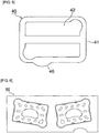
- FIG. 5 shows an example of a lid 40.
- the microneedle patch container 50 and the lid 40 are made of polyethylene terephthalate (PET) and their surfaces are anti-static treated.
- PET polyethylene terephthalate
- the microneedle patch container 50 of the present example is an almost rectangular shape with outer dimensions of approximately 88 x 63 mm and has an almost rectangular bottom surface 52 with a depth of approximately 5 mm and a size of approximately 72 x 49 mm which is recessed from a peripheral portion 51 in the centre.
- the bottom surface 52 is a plane with an almost uniform depth and is continued to the peripheral portion 51 via a side surface 53. Twelve bottom-surface protruding portions 54 are provided from the bottom surface 52. Five of these in upper and lower areas of the figure are almost collinear, respectively.
- Upper parts of the bottom-surface protruding portions 54 are curved, and all of the bottom-surface protruding portions have the same height of approximately 2.5 mm.
- a zone 58 shown by double two-dot chain lines in FIG. 4 shows a site at which the microneedles portion 11 exists when the microneedle patch 10 is contained in the container 30 and does not show structure of the container 50. Then, the microneedle patch 10 is supported by the bottom-surface protruding portions 54 and the side surface convex parts 55, and the microneedles portion 11 does not contact with any part of the container 50.
- the lid 40 for the container of the present example is a rectangular shape with about the same size as the container 50.
- the lid 40 has recessed portions 42 which are recessed from a peripheral portion 41 and matched with the recess of the container.
- the recessed portions 42 correspond to the bottom-surface protruding portions 54 of the container to hold the entire microneedle patch 10 from above and below.
- a protrusion 46 is located outside the lid 40, and a cut 56 is located in a corresponding position outside the container 50. They are provided to easily remove the lid from the container.
- a position where the microneedle patch container 50 and the lid 40 are closely contacted is only on the side surface projections. Accordingly, the microneedle patch is not strongly pressed but caught between the bottom-surface protruding portions of the container and the recessed portions of the lid with a little allowance. Moreover, the recessed portions of the lid are provided in upper and lower areas of the figure, while they are not provided in right and left areas. The microneedle patch is placed on the bottom-surface protruding portions in right and left areas of FIG. 4 , where it is not sandwiched from above.
- FIG. 6 shows an example of a microneedle patch container which can contain two microneedle patches.
- a microneedle patch container 60 may be a container closed by covering with a lid.
- the microneedle patch container 60 is made of polyethylene terephthalate (PET) and its surface is anti-static treated.
- microneedle patch container 60 has two bottom parts provided in a peripheral portion, configuration of each bottom part is similar to that of the container 50, so that further detail is omitted. Moreover, it is considered that the lid of the container 60 can be easily estimated based on FIG. 6 and the lid 40, so that its illustration is omitted. The microneedle patches are held like the case of Example 2.
- FIG. 7 and FIG. 8 show examples of a microneedle patch container in which a microneedle patch holding two microneedle arrays can be contained.
- the two microneedle arrays 68 are held on one piece of release sheet paper.
- adhesive tapes 69 are attached to only a part of the microneedle arrays. By this means, the two microneedle arrays can be easily contained than the case of FIG. 6 .
- FIG. 7 shows the microneedle patch container 60 holding two elongate microneedle arrays. Outer dimensions are slightly bigger than the case of FIG. 2 .
- a bottom surface 62 with a depth of approximately 5 mm recessed from a peripheral portion 61 is provided in the centre.
- An almost oblong bottom-surface protruding portion is provided from the bottom surface.
- the bottom-surface protruding portion may be formed relatively larger than the bottom-surface protruding portion 34 of FIG. 2 to contain the two microneedle arrays.
- a lateral bottom-surface protruding portion may be added between the two microneedle arrays of a central part. Configurations of other parts are similar to FIG. 2 , so that their description is omitted.
- microneedle arrays 68 and an example of the adhesive tape 69 are shown by broken lines in FIG. 7 . These broken lines are illustrations when the microneedle patch is contained in the container, and they do not show structure of the container.
- FIG. 8 shows the microneedle patch container 70 holding two thick microneedle arrays. Outer dimensions are slightly bigger than the case of FIG. 4 .
- a nearly rectangular bottom surface 72 with a depth of approximately 5 mm recessed from a peripheral portion 71 is provided in the centre.
- the bottom surface 72 is a plane with an almost uniform depth and is continued to the peripheral portion 71 via a side surface.
- Twelve bottom-surface protruding portions 74 are provided from the bottom surface 72. Five of these in upper and lower areas of the figure are almost collinear, respectively.
- Upper parts of the bottom-surface protruding portions 74 are curved, and all of the bottom-surface protruding portions have the same height of approximately 2.5 mm. Compared to FIG.
- the bottom-surface protruding portion 74 of FIG. 8 spreads relative to the entire container than the bottom-surface protruding portion 54 of FIG. 4 , to hold the two microneedle arrays. This is because two microneedle arrays are held in a narrow space.
- microneedle arrays 68 and an example of the adhesive tape 69 are shown by broken lines in FIG. 8 . These broken lines are illustrations when the microneedle patch is contained in the container, and they do not show structure of the container.
- FIG. 9 shows a microneedle array with an adhesive sheet provided only in a peripheral portion of the microneedle array.
- the microneedle array comprises the adhesive sheet of course on a surface side where microneedles of the microneedle array are not provided, and it is convenient that the adhesive sheet does not exist on the backside of a part where the microneedles exist.
- Such a microneedle patch holding four microneedle arrays on one piece of release sheet is convenient when the four microneedle patches are used at a time.
- a microneedle patch container 80 of Example 5 may be the same shape as that of Example 4 as shown in FIG. 10 , a container which is larger as a whole is easy to use for containing the four microneedle arrays.
- a bottom surface 82 with a depth of approximately 5 mm recessed from a peripheral portion 81 is provided in the centre.
- An almost oblong bottom-surface protruding portion 84 is provided from the bottom surface. It is convenient that the bottom-surface protruding portion 84 is formed relatively larger than the bottom-surface protruding portion 34 of FIG. 2 to contain the four microneedle arrays.
- a cross or columnar bottom-surface protruding portion may be added between the four microneedle arrays of a central part. Configurations of other parts are similar to FIG. 2 , so that their description is omitted.
- FIG. 9 The four microneedle arrays shown in FIG. 9 are shown by broken lines in FIG. 10 . These broken lines are illustrations when the microneedle patch is contained in the container, and they do not show structure of the container.
Landscapes
- Health & Medical Sciences (AREA)
- Life Sciences & Earth Sciences (AREA)
- Engineering & Computer Science (AREA)
- Animal Behavior & Ethology (AREA)
- Veterinary Medicine (AREA)
- Public Health (AREA)
- General Health & Medical Sciences (AREA)
- Biomedical Technology (AREA)
- Medical Informatics (AREA)
- Heart & Thoracic Surgery (AREA)
- Surgery (AREA)
- Dermatology (AREA)
- Anesthesiology (AREA)
- Hematology (AREA)
- Molecular Biology (AREA)
- Nuclear Medicine, Radiotherapy & Molecular Imaging (AREA)
- Pharmacology & Pharmacy (AREA)
- Media Introduction/Drainage Providing Device (AREA)
- Infusion, Injection, And Reservoir Apparatuses (AREA)
- Packages (AREA)
Claims (11)
- Behälter (30, 50, 70, 80) für Mikronadelpflaster, der Folgendes umfasst:eine oder mehrere Bodenoberflächen (32, 52, 72, 82), die von einem Umfangsabschnitt (31, 51, 71, 81) abgesenkt sind;eine Seitenoberfläche (33, 53), die die Bodenoberflächen (32, 52, 72, 82) mit dem Umfangsabschnitt (31, 51, 71, 81) durchgehend verbindet; undeinen aus den Bodenoberflächen vorstehenden Abschnitt (34, 54, 74, 84), der aus den Bodenoberflächen (32, 52, 72, 82) vorragt,wobei der Behälter (30, 50, 70, 80) ein flexibles Mikronadelpflaster (10) enthält und ein Abziehfolienabschnitt (13) des flexiblen Mikronadelpflasters (10) mit dem aus den Bodenoberflächen vorstehenden Abschnitt (34, 54, 74, 84) jeder der Bodenoberflächen (32, 52, 72, 82) gehalten wird.
- Behälter für Mikronadelpflaster nach Anspruch 1, der einen Deckel (20, 40) umfasst, wobei
der Deckel (20, 40) abgesenkte Abschnitte (22, 42) besitzt, die das Mikronadelpflaster (10), das auf dem aus den Bodenoberflächen vorstehenden Abschnitt (34, 54, 74, 84) gehalten wird, in eine Position drücken, die einem Teil des aus den Bodenoberflächen vorstehenden Abschnitts (34, 54, 74, 84) entspricht, und
der Deckel (20, 40) in einer Position, die einem anderen Teil des aus den Bodenoberflächen vorstehenden Abschnitts (34, 54, 74, 84) entspricht, keine abgesenkten Abschnitte besitzt. - Behälter für Mikronadelpflaster nach Anspruch 2, dadurch gekennzeichnet, dass ein Bereich des aus den Bodenoberflächen vorstehenden Abschnitts (34, 54, 74, 84) des Behälters (30, 50, 70, 80) größer als ein Bereich des abgesenkten Abschnitts (22, 42) des Deckelabschnitts ist.
- Behälter für Mikronadelpflaster nach einem der Ansprüche 1 bis 3, dadurch gekennzeichnet, dass der aus den Bodenoberflächen vorstehende Abschnitt (34, 54, 74, 84) eine rechteckige Form besitzt.
- Behälter für Mikronadelpflaster nach einem der Ansprüche 1 bis 3, dadurch gekennzeichnet, dass die aus den Bodenoberflächen vorstehenden Abschnitte (34, 54) so angeordnet sind, dass mehrere konvexe Teile (35, 55) vier Seiten der Abziehfolie (13) von Mikronadeln tragen.
- Behälter für Mikronadelpflaster nach einem der Ansprüche 1 bis 5, wobei ein Mikronadelpflaster (10), das zwei oder mehr Mikronadelreihen (11) hält, enthalten ist.
- Behälter für Mikronadelpflaster nach Anspruch 2, dadurch gekennzeichnet, dass
die Abziehfolie (13) des Mikronadelpflasters (10) durch einen Bodenteil eines anderen Behälters (30, 50, 70, 80) für Mikronadelpflaster anstelle des Deckels (20, 40) teilweise gedrückt wird und
die Behälter (30, 50, 70, 80) für Mikronadeln aufeinandergestapelt werden können. - Behälter für Mikronadelpflaster nach Anspruch 2, dadurch gekennzeichnet, dass er einen Einschnitt (36, 56) und eine Vorwölbung (26, 46) in entsprechenden Positionen des Behälters (30, 50, 70, 80) für Mikronadelpflaster und des Deckels (20, 40) umfasst.
- Behälter für Mikronadelpflaster nach einem der Ansprüche 1 bis 7, dadurch gekennzeichnet, dass ein verdickter Teil zum einfachen Nehmen des Mikronadelpflasters (10) in der einen oder den mehreren Bodenoberflächen (32, 52, 72, 82) vorgesehen ist.
- Behälter für Mikronadelpflaster nach einem der Ansprüche 1 bis 9, dadurch gekennzeichnet, dass die Oberflächen antistatisch behandelt sind.
- Behälter für Mikronadelpflaster nach einem der Ansprüche 1, dadurch gekennzeichnet, dass der Umfangsabschnitt (31, 51, 71, 81) des Behälters (30, 50, 70, 80) durch Heißsiegeln mit einer heißsiegelfähigen Folie oder mit der Folie, die mit der Folie und Papier laminiert ist, verschweißt und abgedichtet ist.
Applications Claiming Priority (3)
| Application Number | Priority Date | Filing Date | Title |
|---|---|---|---|
| JP2011090477 | 2011-03-30 | ||
| JP2011225328A JP5687170B2 (ja) | 2011-03-30 | 2011-09-22 | マイクロニードルパッチ収納容器 |
| PCT/JP2012/074048 WO2013042723A1 (ja) | 2011-03-30 | 2012-09-20 | マイクロニードルパッチ収納容器 |
Publications (4)
| Publication Number | Publication Date |
|---|---|
| EP2759313A1 EP2759313A1 (de) | 2014-07-30 |
| EP2759313A4 EP2759313A4 (de) | 2015-08-19 |
| EP2759313B1 EP2759313B1 (de) | 2017-02-01 |
| EP2759313B2 true EP2759313B2 (de) | 2020-06-03 |
Family
ID=47266996
Family Applications (1)
| Application Number | Title | Priority Date | Filing Date |
|---|---|---|---|
| EP12834191.4A Not-in-force EP2759313B2 (de) | 2011-03-30 | 2012-09-20 | Behälter für mikronadelpflaster |
Country Status (5)
| Country | Link |
|---|---|
| US (1) | US9168200B2 (de) |
| EP (1) | EP2759313B2 (de) |
| JP (2) | JP5687170B2 (de) |
| CN (1) | CN103796710B (de) |
| WO (1) | WO2013042723A1 (de) |
Families Citing this family (27)
| Publication number | Priority date | Publication date | Assignee | Title |
|---|---|---|---|---|
| JP5687170B2 (ja) * | 2011-03-30 | 2015-03-18 | コスメディ製薬株式会社 | マイクロニードルパッチ収納容器 |
| JP5903016B2 (ja) | 2012-06-27 | 2016-04-13 | コスメディ製薬株式会社 | マイクロニードルパッチの保護離型シート |
| US11051900B2 (en) * | 2014-04-16 | 2021-07-06 | Viacyte, Inc. | Tools and instruments for use with implantable encapsulation devices |
| US20160039533A1 (en) * | 2014-08-05 | 2016-02-11 | Mary Haley | Anti-static, pressure-sensitive adhesive patch and method of use |
| JP5931155B2 (ja) * | 2014-09-30 | 2016-06-08 | 日本写真印刷株式会社 | マイクロニードルシートの梱包体及びその製造方法 |
| JP6364304B2 (ja) * | 2014-10-01 | 2018-07-25 | 久光製薬株式会社 | 貼付剤及び包装用容器 |
| JP6799913B2 (ja) | 2015-12-04 | 2020-12-16 | コスメディ製薬株式会社 | マイクロニードルパッチ収納具、下側パレット及び上側パレット |
| JP6848182B2 (ja) * | 2016-02-16 | 2021-03-24 | 凸版印刷株式会社 | 経皮投与デバイス収容体 |
| KR20180131554A (ko) | 2016-03-01 | 2018-12-10 | 키토테크 메디컬 인코포레이티드 | 상처 봉합을 위한 마이크로 구조-기반 시스템, 장치, 및 방법 |
| CN109069816B (zh) | 2016-03-16 | 2022-03-25 | 考司美德制药株式会社 | 微针贴片支架 |
| JP6662177B2 (ja) * | 2016-04-22 | 2020-03-11 | 凸版印刷株式会社 | 経皮投与デバイス収容体 |
| WO2018139504A1 (ja) | 2017-01-25 | 2018-08-02 | コスメディ製薬株式会社 | マイクロニードルパッチ適用装置 |
| JP2018192177A (ja) | 2017-05-22 | 2018-12-06 | コスメディ製薬株式会社 | 水溶性化粧用シート保持フィルム |
| JP6931222B2 (ja) | 2017-07-18 | 2021-09-01 | コスメディ製薬株式会社 | マイクロニードルアレイの発泡支持体シート |
| WO2020144574A1 (en) * | 2019-01-07 | 2020-07-16 | 3M Innovative Properties Company | Packaging for microarrays |
| US11809382B2 (en) | 2019-04-01 | 2023-11-07 | Nutanix, Inc. | System and method for supporting versioned objects |
| JP7225396B2 (ja) * | 2019-06-11 | 2023-02-20 | 富士フイルム株式会社 | マイクロニードルアレイユニット及び容器 |
| USD939090S1 (en) | 2020-02-05 | 2021-12-21 | Peace Out Inc. | Microneedling patch |
| US11986613B2 (en) | 2020-02-19 | 2024-05-21 | Kitotech Medical, Inc. | Microstructure systems and methods for pain treatment |
| US12001872B2 (en) | 2020-10-14 | 2024-06-04 | Nutanix, Inc. | Object tiering from local store to cloud store |
| US11900164B2 (en) | 2020-11-24 | 2024-02-13 | Nutanix, Inc. | Intelligent query planning for metric gateway |
| US11822370B2 (en) | 2020-11-26 | 2023-11-21 | Nutanix, Inc. | Concurrent multiprotocol access to an object storage system |
| US12307279B2 (en) | 2021-02-01 | 2025-05-20 | Nutanix, Inc. | System and method of VM recovery on S3 compatible object storage |
| US12032857B2 (en) | 2021-11-22 | 2024-07-09 | Nutanix, Inc. | System and method for shallow copy |
| WO2023159181A1 (en) | 2022-02-18 | 2023-08-24 | Kitotech Medical, Inc. | Force modulating deep skin staples and instruments |
| WO2023171568A1 (ja) | 2022-03-05 | 2023-09-14 | コスメディ製薬株式会社 | マイクロニードルパッチ収納容器 |
| US20250185948A1 (en) * | 2022-03-07 | 2025-06-12 | The Regents Of The University Of California | Wearable aptamer microneedle patch for continuous minimally-invasive biomonitoring |
Citations (4)
| Publication number | Priority date | Publication date | Assignee | Title |
|---|---|---|---|---|
| WO1996019394A1 (en) † | 1994-12-21 | 1996-06-27 | Ethical Pharmaceuticals Limited | Packaging for patches |
| US20070083151A1 (en) † | 2003-12-29 | 2007-04-12 | Carter Chad J | Medical devices and kits including same |
| US20100256568A1 (en) † | 2005-06-27 | 2010-10-07 | Frederickson Franklyn L | Microneedle cartridge assembly and method of applying |
| US20110127188A1 (en) † | 2009-12-01 | 2011-06-02 | Cryovac, Inc. | Method of Using Coextruded Film for Sterile Barrier System to Deliver Seal and Peel Characteristics |
Family Cites Families (33)
| Publication number | Priority date | Publication date | Assignee | Title |
|---|---|---|---|---|
| JPS606334A (ja) * | 1983-06-23 | 1985-01-14 | Toshiba Corp | ダイヤフラム加工装置 |
| JPS6063344U (ja) * | 1983-10-06 | 1985-05-04 | 丸正金属箔工業株式会社 | パツプ剤用容器 |
| JPH10304934A (ja) | 1997-05-08 | 1998-11-17 | Kanebo Ltd | 皮膚集中ケア用具 |
| AU767122B2 (en) | 1998-06-10 | 2003-10-30 | Georgia Tech Research Corporation | Microneedle devices and methods of manufacture and use thereof |
| US6503231B1 (en) | 1998-06-10 | 2003-01-07 | Georgia Tech Research Corporation | Microneedle device for transport of molecules across tissue |
| US7344499B1 (en) | 1998-06-10 | 2008-03-18 | Georgia Tech Research Corporation | Microneedle device for extraction and sensing of bodily fluids |
| US6743211B1 (en) | 1999-11-23 | 2004-06-01 | Georgia Tech Research Corporation | Devices and methods for enhanced microneedle penetration of biological barriers |
| US6611707B1 (en) | 1999-06-04 | 2003-08-26 | Georgia Tech Research Corporation | Microneedle drug delivery device |
| CA2376128C (en) | 1999-06-04 | 2009-01-06 | Georgia Tech Research Corporation | Devices and methods for enhanced microneedle penetration of biological barriers |
| US6622864B1 (en) * | 2000-06-01 | 2003-09-23 | Osteotech, Inc. | Moisture resistant package for storing sterile items |
| ES2237592T3 (es) | 2000-08-18 | 2005-08-01 | Becton Dickinson And Company | Dispositivo de entrega de fluido a caudal constante con caudal seleccionable y boton de bolus regulable. |
| WO2002030300A2 (en) | 2000-10-13 | 2002-04-18 | Alza Corporation | Microprotrusion member retainer for impact applicator |
| JP4090018B2 (ja) | 2002-02-18 | 2008-05-28 | For Head株式会社 | 機能性マイクロパイル及びその製造方法 |
| KR20060108665A (ko) | 2003-10-10 | 2006-10-18 | 액세스 비지니스 그룹 인터내셔날 엘엘씨 | 로즈마리누스 오피시날리스 식물 추출물, 센텔라,에치나세아 또는 알피니아 식물 추출물 및 dna 복구효소를 포함하는 조성물 |
| US7758878B2 (en) | 2003-10-10 | 2010-07-20 | Access Business Group International Llc | Cosmetic treatment system and methods |
| US20060257509A1 (en) | 2003-10-10 | 2006-11-16 | Zimmerman Amy C | Cosmetic composition and methods |
| WO2006041526A1 (en) | 2004-10-07 | 2006-04-20 | Access Business Group International Llc | Composition comprising a rosmarinus officinalis plant extract, an alpinia plant extract and a dna repair enzyme |
| JP2006056543A (ja) | 2004-08-18 | 2006-03-02 | Kanae Technos:Kk | パック用ゲルシート包装体 |
| JP4555032B2 (ja) * | 2004-09-03 | 2010-09-29 | シーエステック株式会社 | トレイ |
| JP2008518042A (ja) | 2004-10-07 | 2008-05-29 | アクセス ビジネス グループ インターナショナル エルエルシー | ローズマリー(Rosmarinusofficinalis)植物抽出物、アルピニア(Alpinia)植物抽出物、及びDNA修復酵素を含む組成物。 |
| JP2006346126A (ja) | 2005-06-15 | 2006-12-28 | Nabtesco Corp | 皮膚用針 |
| EP2062611A4 (de) * | 2006-08-18 | 2010-01-06 | Toppan Printing Co Ltd | Mikronadel und mikronadelstelle |
| ATE547985T1 (de) * | 2006-09-04 | 2012-03-15 | Hoffmann La Roche | Verpackung für hydrophile medizinische instrumente |
| JP2008284318A (ja) | 2007-05-15 | 2008-11-27 | Kosumedei Seiyaku Kk | 生体由来物質からなる投薬用微細針 |
| CA2695731C (en) * | 2007-08-06 | 2018-04-03 | Transderm, Inc. | Microneedle arrays formed from polymer films |
| JP2010029512A (ja) * | 2008-07-30 | 2010-02-12 | Seirin Kk | 薬剤付き鍼灸針 |
| JP5572301B2 (ja) | 2008-09-26 | 2014-08-13 | 凸版印刷株式会社 | マイクロニードル保持容器 |
| JP5503859B2 (ja) * | 2008-09-26 | 2014-05-28 | 凸版印刷株式会社 | マイクロニードル保持容器 |
| JP3152532U (ja) * | 2009-04-22 | 2009-08-06 | コスメディ製薬株式会社 | マイクロニードルパッチ収納ケース |
| JP2011090477A (ja) | 2009-10-22 | 2011-05-06 | Sharp Corp | 情報処理装置、サーバ装置、通信システム、データ通信方法、プログラム、およびコンピュータ読み取り可能な記録媒体 |
| JP5668962B2 (ja) | 2010-04-19 | 2015-02-12 | 村田機械株式会社 | 自動原稿送り装置及びそれを備える原稿読取装置 |
| JP2013538069A (ja) * | 2010-07-16 | 2013-10-10 | セブンス センス バイオシステムズ,インコーポレーテッド | 流体移動デバイスのための低圧環境 |
| JP5687170B2 (ja) * | 2011-03-30 | 2015-03-18 | コスメディ製薬株式会社 | マイクロニードルパッチ収納容器 |
-
2011
- 2011-09-22 JP JP2011225328A patent/JP5687170B2/ja active Active
-
2012
- 2012-09-20 CN CN201280044608.3A patent/CN103796710B/zh active Active
- 2012-09-20 EP EP12834191.4A patent/EP2759313B2/de not_active Not-in-force
- 2012-09-20 US US14/345,567 patent/US9168200B2/en active Active
- 2012-09-20 WO PCT/JP2012/074048 patent/WO2013042723A1/ja not_active Ceased
-
2015
- 2015-01-21 JP JP2015009208A patent/JP6092270B2/ja active Active
Patent Citations (4)
| Publication number | Priority date | Publication date | Assignee | Title |
|---|---|---|---|---|
| WO1996019394A1 (en) † | 1994-12-21 | 1996-06-27 | Ethical Pharmaceuticals Limited | Packaging for patches |
| US20070083151A1 (en) † | 2003-12-29 | 2007-04-12 | Carter Chad J | Medical devices and kits including same |
| US20100256568A1 (en) † | 2005-06-27 | 2010-10-07 | Frederickson Franklyn L | Microneedle cartridge assembly and method of applying |
| US20110127188A1 (en) † | 2009-12-01 | 2011-06-02 | Cryovac, Inc. | Method of Using Coextruded Film for Sterile Barrier System to Deliver Seal and Peel Characteristics |
Also Published As
| Publication number | Publication date |
|---|---|
| CN103796710A (zh) | 2014-05-14 |
| US20140339117A1 (en) | 2014-11-20 |
| WO2013042723A1 (ja) | 2013-03-28 |
| JP2012213586A (ja) | 2012-11-08 |
| JP6092270B2 (ja) | 2017-03-08 |
| EP2759313A4 (de) | 2015-08-19 |
| CN103796710B (zh) | 2017-02-15 |
| EP2759313B1 (de) | 2017-02-01 |
| JP5687170B2 (ja) | 2015-03-18 |
| US9168200B2 (en) | 2015-10-27 |
| JP2015083503A (ja) | 2015-04-30 |
| EP2759313A1 (de) | 2014-07-30 |
Similar Documents
| Publication | Publication Date | Title |
|---|---|---|
| EP2759313B1 (de) | Behälter für mikronadelpflaster | |
| JP5947873B2 (ja) | マイクロニードルパッチ収納容器2 | |
| CN205007427U (zh) | 一种微针贴片及包装盒 | |
| EP1896115B1 (de) | Mikronadelkartuschenanordnung | |
| EP3246066B1 (de) | Aufnahmekörper für vorrichtung zur transdermalen verabreichung | |
| JP3152532U (ja) | マイクロニードルパッチ収納ケース | |
| JP6020771B2 (ja) | 経皮投与デバイス、および、経皮投与デバイスの製造方法 | |
| WO2012029127A1 (ja) | 貼付体シート、及び、その使用、並びに、貼付体シートの貼付方法 | |
| KR20170063591A (ko) | 마이크로니들 시트의 곤포체 및 그 제조 방법 | |
| US10589017B2 (en) | Package for medical product | |
| US20200164192A1 (en) | Water-soluble cosmetic sheet retaining film | |
| KR20160138152A (ko) | 추체상 돌기 시트의 곤포체 및 그 제조 방법 | |
| JP3179380U (ja) | マイクロニードルパッチ2枚収納容器 | |
| KR101990654B1 (ko) | 마이크로니들 패치 수납 용기 | |
| CN110678103A (zh) | 具有储集器的多用途非接触式施用器 | |
| CN217865928U (zh) | 一种微针贴片包装体及微针贴片产品 | |
| CN208585535U (zh) | 一种微针贴片内包装盒 | |
| CN214970273U (zh) | 一次性使用正压接头消毒贴 | |
| CN215129163U (zh) | 一种一次性使用肝脏穿刺活检包 | |
| JP5384730B2 (ja) | 貼付体シート | |
| WO2015195508A1 (en) | Frozen therapeutic dose and package |
Legal Events
| Date | Code | Title | Description |
|---|---|---|---|
| PUAI | Public reference made under article 153(3) epc to a published international application that has entered the european phase |
Free format text: ORIGINAL CODE: 0009012 |
|
| 17P | Request for examination filed |
Effective date: 20140314 |
|
| AK | Designated contracting states |
Kind code of ref document: A1 Designated state(s): AL AT BE BG CH CY CZ DE DK EE ES FI FR GB GR HR HU IE IS IT LI LT LU LV MC MK MT NL NO PL PT RO RS SE SI SK SM TR |
|
| DAX | Request for extension of the european patent (deleted) | ||
| RA4 | Supplementary search report drawn up and despatched (corrected) |
Effective date: 20150716 |
|
| RIC1 | Information provided on ipc code assigned before grant |
Ipc: A61J 1/00 20060101ALI20150710BHEP Ipc: A61M 37/00 20060101AFI20150710BHEP Ipc: A61B 19/02 20060101ALI20150710BHEP Ipc: A61M 5/00 20060101ALI20150710BHEP |
|
| 17Q | First examination report despatched |
Effective date: 20160301 |
|
| GRAP | Despatch of communication of intention to grant a patent |
Free format text: ORIGINAL CODE: EPIDOSNIGR1 |
|
| RIC1 | Information provided on ipc code assigned before grant |
Ipc: A61J 1/00 20060101ALI20160706BHEP Ipc: A61M 37/00 20060101AFI20160706BHEP Ipc: A61B 50/00 20160101ALI20160706BHEP Ipc: A61M 5/00 20060101ALI20160706BHEP Ipc: A61B 50/30 20160101ALI20160706BHEP |
|
| INTG | Intention to grant announced |
Effective date: 20160802 |
|
| GRAJ | Information related to disapproval of communication of intention to grant by the applicant or resumption of examination proceedings by the epo deleted |
Free format text: ORIGINAL CODE: EPIDOSDIGR1 |
|
| STAA | Information on the status of an ep patent application or granted ep patent |
Free format text: STATUS: EXAMINATION IS IN PROGRESS |
|
| GRAR | Information related to intention to grant a patent recorded |
Free format text: ORIGINAL CODE: EPIDOSNIGR71 |
|
| GRAS | Grant fee paid |
Free format text: ORIGINAL CODE: EPIDOSNIGR3 |
|
| STAA | Information on the status of an ep patent application or granted ep patent |
Free format text: STATUS: GRANT OF PATENT IS INTENDED |
|
| INTC | Intention to grant announced (deleted) | ||
| GRAA | (expected) grant |
Free format text: ORIGINAL CODE: 0009210 |
|
| STAA | Information on the status of an ep patent application or granted ep patent |
Free format text: STATUS: THE PATENT HAS BEEN GRANTED |
|
| INTG | Intention to grant announced |
Effective date: 20161220 |
|
| AK | Designated contracting states |
Kind code of ref document: B1 Designated state(s): AL AT BE BG CH CY CZ DE DK EE ES FI FR GB GR HR HU IE IS IT LI LT LU LV MC MK MT NL NO PL PT RO RS SE SI SK SM TR |
|
| REG | Reference to a national code |
Ref country code: GB Ref legal event code: FG4D |
|
| REG | Reference to a national code |
Ref country code: CH Ref legal event code: EP Ref country code: AT Ref legal event code: REF Ref document number: 865023 Country of ref document: AT Kind code of ref document: T Effective date: 20170215 |
|
| REG | Reference to a national code |
Ref country code: IE Ref legal event code: FG4D |
|
| REG | Reference to a national code |
Ref country code: DE Ref legal event code: R096 Ref document number: 602012028416 Country of ref document: DE |
|
| REG | Reference to a national code |
Ref country code: NL Ref legal event code: MP Effective date: 20170201 |
|
| REG | Reference to a national code |
Ref country code: LT Ref legal event code: MG4D |
|
| REG | Reference to a national code |
Ref country code: AT Ref legal event code: MK05 Ref document number: 865023 Country of ref document: AT Kind code of ref document: T Effective date: 20170201 |
|
| PG25 | Lapsed in a contracting state [announced via postgrant information from national office to epo] |
Ref country code: LT Free format text: LAPSE BECAUSE OF FAILURE TO SUBMIT A TRANSLATION OF THE DESCRIPTION OR TO PAY THE FEE WITHIN THE PRESCRIBED TIME-LIMIT Effective date: 20170201 Ref country code: FI Free format text: LAPSE BECAUSE OF FAILURE TO SUBMIT A TRANSLATION OF THE DESCRIPTION OR TO PAY THE FEE WITHIN THE PRESCRIBED TIME-LIMIT Effective date: 20170201 Ref country code: NO Free format text: LAPSE BECAUSE OF FAILURE TO SUBMIT A TRANSLATION OF THE DESCRIPTION OR TO PAY THE FEE WITHIN THE PRESCRIBED TIME-LIMIT Effective date: 20170501 Ref country code: GR Free format text: LAPSE BECAUSE OF FAILURE TO SUBMIT A TRANSLATION OF THE DESCRIPTION OR TO PAY THE FEE WITHIN THE PRESCRIBED TIME-LIMIT Effective date: 20170502 Ref country code: HR Free format text: LAPSE BECAUSE OF FAILURE TO SUBMIT A TRANSLATION OF THE DESCRIPTION OR TO PAY THE FEE WITHIN THE PRESCRIBED TIME-LIMIT Effective date: 20170201 Ref country code: IS Free format text: LAPSE BECAUSE OF FAILURE TO SUBMIT A TRANSLATION OF THE DESCRIPTION OR TO PAY THE FEE WITHIN THE PRESCRIBED TIME-LIMIT Effective date: 20170601 |
|
| PG25 | Lapsed in a contracting state [announced via postgrant information from national office to epo] |
Ref country code: PL Free format text: LAPSE BECAUSE OF FAILURE TO SUBMIT A TRANSLATION OF THE DESCRIPTION OR TO PAY THE FEE WITHIN THE PRESCRIBED TIME-LIMIT Effective date: 20170201 Ref country code: ES Free format text: LAPSE BECAUSE OF FAILURE TO SUBMIT A TRANSLATION OF THE DESCRIPTION OR TO PAY THE FEE WITHIN THE PRESCRIBED TIME-LIMIT Effective date: 20170201 Ref country code: NL Free format text: LAPSE BECAUSE OF FAILURE TO SUBMIT A TRANSLATION OF THE DESCRIPTION OR TO PAY THE FEE WITHIN THE PRESCRIBED TIME-LIMIT Effective date: 20170201 Ref country code: RS Free format text: LAPSE BECAUSE OF FAILURE TO SUBMIT A TRANSLATION OF THE DESCRIPTION OR TO PAY THE FEE WITHIN THE PRESCRIBED TIME-LIMIT Effective date: 20170201 Ref country code: BG Free format text: LAPSE BECAUSE OF FAILURE TO SUBMIT A TRANSLATION OF THE DESCRIPTION OR TO PAY THE FEE WITHIN THE PRESCRIBED TIME-LIMIT Effective date: 20170501 Ref country code: AT Free format text: LAPSE BECAUSE OF FAILURE TO SUBMIT A TRANSLATION OF THE DESCRIPTION OR TO PAY THE FEE WITHIN THE PRESCRIBED TIME-LIMIT Effective date: 20170201 Ref country code: PT Free format text: LAPSE BECAUSE OF FAILURE TO SUBMIT A TRANSLATION OF THE DESCRIPTION OR TO PAY THE FEE WITHIN THE PRESCRIBED TIME-LIMIT Effective date: 20170601 Ref country code: SE Free format text: LAPSE BECAUSE OF FAILURE TO SUBMIT A TRANSLATION OF THE DESCRIPTION OR TO PAY THE FEE WITHIN THE PRESCRIBED TIME-LIMIT Effective date: 20170201 Ref country code: LV Free format text: LAPSE BECAUSE OF FAILURE TO SUBMIT A TRANSLATION OF THE DESCRIPTION OR TO PAY THE FEE WITHIN THE PRESCRIBED TIME-LIMIT Effective date: 20170201 |
|
| REG | Reference to a national code |
Ref country code: FR Ref legal event code: PLFP Year of fee payment: 6 |
|
| PG25 | Lapsed in a contracting state [announced via postgrant information from national office to epo] |
Ref country code: IT Free format text: LAPSE BECAUSE OF FAILURE TO SUBMIT A TRANSLATION OF THE DESCRIPTION OR TO PAY THE FEE WITHIN THE PRESCRIBED TIME-LIMIT Effective date: 20170201 Ref country code: CZ Free format text: LAPSE BECAUSE OF FAILURE TO SUBMIT A TRANSLATION OF THE DESCRIPTION OR TO PAY THE FEE WITHIN THE PRESCRIBED TIME-LIMIT Effective date: 20170201 Ref country code: EE Free format text: LAPSE BECAUSE OF FAILURE TO SUBMIT A TRANSLATION OF THE DESCRIPTION OR TO PAY THE FEE WITHIN THE PRESCRIBED TIME-LIMIT Effective date: 20170201 Ref country code: SK Free format text: LAPSE BECAUSE OF FAILURE TO SUBMIT A TRANSLATION OF THE DESCRIPTION OR TO PAY THE FEE WITHIN THE PRESCRIBED TIME-LIMIT Effective date: 20170201 Ref country code: RO Free format text: LAPSE BECAUSE OF FAILURE TO SUBMIT A TRANSLATION OF THE DESCRIPTION OR TO PAY THE FEE WITHIN THE PRESCRIBED TIME-LIMIT Effective date: 20170201 |
|
| REG | Reference to a national code |
Ref country code: DE Ref legal event code: R026 Ref document number: 602012028416 Country of ref document: DE |
|
| PLBI | Opposition filed |
Free format text: ORIGINAL CODE: 0009260 |
|
| PG25 | Lapsed in a contracting state [announced via postgrant information from national office to epo] |
Ref country code: SM Free format text: LAPSE BECAUSE OF FAILURE TO SUBMIT A TRANSLATION OF THE DESCRIPTION OR TO PAY THE FEE WITHIN THE PRESCRIBED TIME-LIMIT Effective date: 20170201 Ref country code: DK Free format text: LAPSE BECAUSE OF FAILURE TO SUBMIT A TRANSLATION OF THE DESCRIPTION OR TO PAY THE FEE WITHIN THE PRESCRIBED TIME-LIMIT Effective date: 20170201 |
|
| 26 | Opposition filed |
Opponent name: LTS LOHMANN THERAPIE-SYSTEME AG Effective date: 20171102 |
|
| PG25 | Lapsed in a contracting state [announced via postgrant information from national office to epo] |
Ref country code: SI Free format text: LAPSE BECAUSE OF FAILURE TO SUBMIT A TRANSLATION OF THE DESCRIPTION OR TO PAY THE FEE WITHIN THE PRESCRIBED TIME-LIMIT Effective date: 20170201 |
|
| PLAX | Notice of opposition and request to file observation + time limit sent |
Free format text: ORIGINAL CODE: EPIDOSNOBS2 |
|
| REG | Reference to a national code |
Ref country code: CH Ref legal event code: PL |
|
| PG25 | Lapsed in a contracting state [announced via postgrant information from national office to epo] |
Ref country code: MC Free format text: LAPSE BECAUSE OF FAILURE TO SUBMIT A TRANSLATION OF THE DESCRIPTION OR TO PAY THE FEE WITHIN THE PRESCRIBED TIME-LIMIT Effective date: 20170201 |
|
| REG | Reference to a national code |
Ref country code: IE Ref legal event code: MM4A |
|
| REG | Reference to a national code |
Ref country code: BE Ref legal event code: MM Effective date: 20170930 |
|
| PG25 | Lapsed in a contracting state [announced via postgrant information from national office to epo] |
Ref country code: LU Free format text: LAPSE BECAUSE OF NON-PAYMENT OF DUE FEES Effective date: 20170920 |
|
| PLBB | Reply of patent proprietor to notice(s) of opposition received |
Free format text: ORIGINAL CODE: EPIDOSNOBS3 |
|
| PG25 | Lapsed in a contracting state [announced via postgrant information from national office to epo] |
Ref country code: IE Free format text: LAPSE BECAUSE OF NON-PAYMENT OF DUE FEES Effective date: 20170920 Ref country code: LI Free format text: LAPSE BECAUSE OF NON-PAYMENT OF DUE FEES Effective date: 20170930 Ref country code: CH Free format text: LAPSE BECAUSE OF NON-PAYMENT OF DUE FEES Effective date: 20170930 |
|
| PG25 | Lapsed in a contracting state [announced via postgrant information from national office to epo] |
Ref country code: BE Free format text: LAPSE BECAUSE OF NON-PAYMENT OF DUE FEES Effective date: 20170930 |
|
| REG | Reference to a national code |
Ref country code: FR Ref legal event code: PLFP Year of fee payment: 7 |
|
| PG25 | Lapsed in a contracting state [announced via postgrant information from national office to epo] |
Ref country code: MT Free format text: LAPSE BECAUSE OF NON-PAYMENT OF DUE FEES Effective date: 20170920 |
|
| PG25 | Lapsed in a contracting state [announced via postgrant information from national office to epo] |
Ref country code: HU Free format text: LAPSE BECAUSE OF FAILURE TO SUBMIT A TRANSLATION OF THE DESCRIPTION OR TO PAY THE FEE WITHIN THE PRESCRIBED TIME-LIMIT; INVALID AB INITIO Effective date: 20120920 |
|
| APBM | Appeal reference recorded |
Free format text: ORIGINAL CODE: EPIDOSNREFNO |
|
| APBP | Date of receipt of notice of appeal recorded |
Free format text: ORIGINAL CODE: EPIDOSNNOA2O |
|
| PG25 | Lapsed in a contracting state [announced via postgrant information from national office to epo] |
Ref country code: CY Free format text: LAPSE BECAUSE OF NON-PAYMENT OF DUE FEES Effective date: 20170201 |
|
| APAH | Appeal reference modified |
Free format text: ORIGINAL CODE: EPIDOSCREFNO |
|
| PG25 | Lapsed in a contracting state [announced via postgrant information from national office to epo] |
Ref country code: MK Free format text: LAPSE BECAUSE OF FAILURE TO SUBMIT A TRANSLATION OF THE DESCRIPTION OR TO PAY THE FEE WITHIN THE PRESCRIBED TIME-LIMIT Effective date: 20170201 |
|
| APBU | Appeal procedure closed |
Free format text: ORIGINAL CODE: EPIDOSNNOA9O |
|
| PG25 | Lapsed in a contracting state [announced via postgrant information from national office to epo] |
Ref country code: TR Free format text: LAPSE BECAUSE OF FAILURE TO SUBMIT A TRANSLATION OF THE DESCRIPTION OR TO PAY THE FEE WITHIN THE PRESCRIBED TIME-LIMIT Effective date: 20170201 |
|
| PUAH | Patent maintained in amended form |
Free format text: ORIGINAL CODE: 0009272 |
|
| STAA | Information on the status of an ep patent application or granted ep patent |
Free format text: STATUS: PATENT MAINTAINED AS AMENDED |
|
| 27A | Patent maintained in amended form |
Effective date: 20200603 |
|
| AK | Designated contracting states |
Kind code of ref document: B2 Designated state(s): AL AT BE BG CH CY CZ DE DK EE ES FI FR GB GR HR HU IE IS IT LI LT LU LV MC MK MT NL NO PL PT RO RS SE SI SK SM TR |
|
| REG | Reference to a national code |
Ref country code: DE Ref legal event code: R102 Ref document number: 602012028416 Country of ref document: DE |
|
| PG25 | Lapsed in a contracting state [announced via postgrant information from national office to epo] |
Ref country code: AL Free format text: LAPSE BECAUSE OF FAILURE TO SUBMIT A TRANSLATION OF THE DESCRIPTION OR TO PAY THE FEE WITHIN THE PRESCRIBED TIME-LIMIT Effective date: 20170201 |
|
| P01 | Opt-out of the competence of the unified patent court (upc) registered |
Effective date: 20230606 |
|
| PGFP | Annual fee paid to national office [announced via postgrant information from national office to epo] |
Ref country code: GB Payment date: 20230921 Year of fee payment: 12 |
|
| PGFP | Annual fee paid to national office [announced via postgrant information from national office to epo] |
Ref country code: FR Payment date: 20230918 Year of fee payment: 12 Ref country code: DE Payment date: 20230926 Year of fee payment: 12 |
|
| REG | Reference to a national code |
Ref country code: DE Ref legal event code: R119 Ref document number: 602012028416 Country of ref document: DE |
|
| GBPC | Gb: european patent ceased through non-payment of renewal fee |
Effective date: 20240920 |
|
| PG25 | Lapsed in a contracting state [announced via postgrant information from national office to epo] |
Ref country code: DE Free format text: LAPSE BECAUSE OF NON-PAYMENT OF DUE FEES Effective date: 20250401 |
|
| PG25 | Lapsed in a contracting state [announced via postgrant information from national office to epo] |
Ref country code: GB Free format text: LAPSE BECAUSE OF NON-PAYMENT OF DUE FEES Effective date: 20240920 |
|
| PG25 | Lapsed in a contracting state [announced via postgrant information from national office to epo] |
Ref country code: FR Free format text: LAPSE BECAUSE OF NON-PAYMENT OF DUE FEES Effective date: 20240930 |