EP2757665B1 - Elektrische antriebsvorrichtung - Google Patents
Elektrische antriebsvorrichtung Download PDFInfo
- Publication number
- EP2757665B1 EP2757665B1 EP11872253.7A EP11872253A EP2757665B1 EP 2757665 B1 EP2757665 B1 EP 2757665B1 EP 11872253 A EP11872253 A EP 11872253A EP 2757665 B1 EP2757665 B1 EP 2757665B1
- Authority
- EP
- European Patent Office
- Prior art keywords
- motor
- terminal
- drive unit
- terminals
- electric
- Prior art date
- Legal status (The legal status is an assumption and is not a legal conclusion. Google has not performed a legal analysis and makes no representation as to the accuracy of the status listed.)
- Active
Links
Images


Classifications
-
- H—ELECTRICITY
- H02—GENERATION; CONVERSION OR DISTRIBUTION OF ELECTRIC POWER
- H02K—DYNAMO-ELECTRIC MACHINES
- H02K11/00—Structural association of dynamo-electric machines with electric components or with devices for shielding, monitoring or protection
- H02K11/30—Structural association with control circuits or drive circuits
- H02K11/38—Control circuits or drive circuits associated with geared commutator motors of the worm-and-wheel type
-
- B—PERFORMING OPERATIONS; TRANSPORTING
- B62—LAND VEHICLES FOR TRAVELLING OTHERWISE THAN ON RAILS
- B62D—MOTOR VEHICLES; TRAILERS
- B62D5/00—Power-assisted or power-driven steering
- B62D5/04—Power-assisted or power-driven steering electrical, e.g. using an electric servo-motor connected to, or forming part of, the steering gear
- B62D5/0403—Power-assisted or power-driven steering electrical, e.g. using an electric servo-motor connected to, or forming part of, the steering gear characterised by constructional features, e.g. common housing for motor and gear box
- B62D5/0406—Power-assisted or power-driven steering electrical, e.g. using an electric servo-motor connected to, or forming part of, the steering gear characterised by constructional features, e.g. common housing for motor and gear box including housing for electronic control unit
-
- H—ELECTRICITY
- H02—GENERATION; CONVERSION OR DISTRIBUTION OF ELECTRIC POWER
- H02K—DYNAMO-ELECTRIC MACHINES
- H02K11/00—Structural association of dynamo-electric machines with electric components or with devices for shielding, monitoring or protection
- H02K11/20—Structural association of dynamo-electric machines with electric components or with devices for shielding, monitoring or protection for measuring, monitoring, testing, protecting or switching
- H02K11/21—Devices for sensing speed or position, or actuated thereby
- H02K11/225—Detecting coils
-
- H—ELECTRICITY
- H01—ELECTRIC ELEMENTS
- H01R—ELECTRICALLY-CONDUCTIVE CONNECTIONS; STRUCTURAL ASSOCIATIONS OF A PLURALITY OF MUTUALLY-INSULATED ELECTRICAL CONNECTING ELEMENTS; COUPLING DEVICES; CURRENT COLLECTORS
- H01R13/00—Details of coupling devices of the kinds covered by groups H01R12/70 or H01R24/00 - H01R33/00
- H01R13/02—Contact members
- H01R13/10—Sockets for co-operation with pins or blades
- H01R13/11—Resilient sockets
- H01R13/112—Resilient sockets forked sockets having two legs
-
- H—ELECTRICITY
- H02—GENERATION; CONVERSION OR DISTRIBUTION OF ELECTRIC POWER
- H02K—DYNAMO-ELECTRIC MACHINES
- H02K3/00—Details of windings
- H02K3/46—Fastening of windings on the stator or rotor structure
- H02K3/52—Fastening salient pole windings or connections thereto
- H02K3/521—Fastening salient pole windings or connections thereto applicable to stators only
- H02K3/522—Fastening salient pole windings or connections thereto applicable to stators only for generally annular cores with salient poles
-
- H—ELECTRICITY
- H02—GENERATION; CONVERSION OR DISTRIBUTION OF ELECTRIC POWER
- H02K—DYNAMO-ELECTRIC MACHINES
- H02K5/00—Casings; Enclosures; Supports
- H02K5/04—Casings or enclosures characterised by the shape, form or construction thereof
- H02K5/22—Auxiliary parts of casings not covered by groups H02K5/06-H02K5/20, e.g. shaped to form connection boxes or terminal boxes
- H02K5/225—Terminal boxes or connection arrangements
Definitions
- the present invention relates to an electric drive unit including an electric motor that outputs an assist torque to a steering wheel of a vehicle and a control apparatus that controls the driving of the electric motor, for example, an electric drive unit employed in an electric power steering apparatus.
- an electric drive unit including an electric motor that outputs an assist torque to a steering wheel of a vehicle and a control apparatus that controls the driving of the electric motor and formed by attaching the control apparatus to the electric motor.
- an electric power steering apparatus described, for example, in PLT 1 is proposed.
- a control unit serving as the control apparatus is disposed on an axis line of a rotation shaft of the electric motor and fixed to the electric motor.
- a power feeding portion of the electric motor and a join t region of the control unit are joined using screws inside a housing or a case through an opening provided to the housing or the case or the both.
- PLT 1 JP-A-2009-248754 ( Fig. 2 )
- EP 1 955 927 A1 discloses features falling under the preamble of claim 1.
- US 2009/250287 A1 , US 2007/278873 A1 , and US 5,218,255 A are further prior art.
- the electric drive unit employed in the electric power steering apparatus described in PLT 1 requires screws to electrically connect the power feeding portion of the electric motor and the joint region of the control apparatus. Also, in order to join these portions using screws, an installation space for screws and an insertion space for a screw tightening tool are required. Consequently, the number of components and assembly man-hours are increased, which poses a problem that not only does the cost increase but a size of the unit also increases.
- the power feeding portion and the join t region are joined by tightening screws using a screw tightening tool from the opening.
- foreign matter dust, water drop, and the like
- a water droplet may possibly adhere to the joining part and give rise to the formation of rust, in which case conductivity becomes poor.
- it is necessary to close the insertion opening for the screw tightening tool by additionally using a cover after the screws are tightened. This configuration, however, has a problem that the number of components and assembly man-hours are increased and the cost is increased further.
- the invention was devised to solve the problems discussed above and has an object to provide an electric drive unit which is an electric drive unit including an electric motor and a control apparatus and formed by reducing the number of components and assembly man-hours.
- An electric drive unit of the invention is an electric drive unit according to claim 1.
- an electric drive unit which is an electric drive unit including an electric motor and a control apparatus and formed by reducing the number of components and assembly man-hours.
- the passive elements are provided to the frame with which the conductive plates are integrally molded and the terminals are individually connected to the conductive plates. It is therefore possible to provide an electric drive unit with enhanced assembly workability.
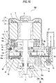
- Fig. 1 through Fig. 3 are, respectively, a cross section, an exploded perspective view, and a circuit diagram of an electric drive unit 100 according to the first embodiment of the invention.
- the electric drive unit 100 according to the first embodiment of the invention is an electric drive unit employed in an electric power steering apparatus and includes an electric motor 1 that outputs an assist torque to a steering wheel of a vehicle and a control apparatus 20 that controls the driving of the electric motor 1.
- the electric motor 1 is a three-phase brushless motor and includes a rotation shaft 2, a rotor 4 formed of a cylindrical permanent magnet 3 having, for example, ten magnetic polarity poles and fixed to the rotation shaft 2, a stator 5 provided so as to surround the rotor 4, an iron yoke 6 used to fix the stator 5, and a coupling 7 fixed at an end of the rotation shaft 2 to transmit a torque of the electric motor 1.
- the stator 5 has, for example, 12 salient poles 8 opposing an outer periphery of the permanent magnet 3 and armature windings 10 wound via insulators 9 attached to the salient poles 8 and connected to three phases including phases U, V, and W.
- the armature windings 10 are, for example, delta connected. Respective winding ends are crimped with three terminals (intermediate members) 12U, 12V, and 12W supported on a doughnut-shaped holder 11 made of an insulating resin material and connected by joining means, such as welding.
- the permanent magnet 3 has ten polarity poles and the stator 5 has 12 salient poles.
- the holder 11 of an annular shape is provided with as many concave groove portions (supporting portions) 11a as terminals 12 in a concentric fashion.
- the respective arc-like terminals 12 are supported on the groove portions 11a.
- the terminals 12 are crimped with motor terminals (first terminal) 13 provided in an equal number to the number of the terminals 12 and extending parallel to an axis line of the rotation shaft 2 from the electric motor 1 toward the control apparatus 20, and connected by joining means, such as welding.
- the motor terminals 13 are located on a radially outer side than the groove portions 11a.
- the terminals 12 are made of copper alloy having lower heat-resistant creep characteristics than the motor terminals 13.
- creep referred to herein means deformation occurring after an elapse of certain time in a material kept at a constant temperature under a constant stress.
- a material having high heat-resistant creep characteristics means a material that undergoes a small degree of heat-induced deterioration with time (degree of deformation) under a constant stress.
- Fig. 4 is a front view of a major portion of the motor terminal 13 of Fig. 1 .
- the motor terminal 13 is, for example, of a column shape and provided with a slit 13a at an end on the side of the control apparatus 20. Two arm portions 13b are formed by this slit 13a.
- an end on the side of the electric motor 1 is bent in the shape of a capital L by a bending portion 13d and forms an end face 13e perpendicular to an axial direction of the rotation shaft 2.
- Tapers 13c1 are provided on the both sides of the slit 13a at tip ends of the respective arm portions 13b on the side where the slit 13a is provided (on the inner side of the motor terminal 13, see Fig. 4 ) in such a manner that a slit width W increases gradually toward the tip ends, that is, a width of the arm portions 13b decreases gradually.
- the end face 13e is supported on an abutment surface 11b of the holder 11 by abutting thereon in the axial direction.
- tapers 13c2 are also provided at the tip ends of the arm portions 13b on the sides where the slit 13a is not provided (on the outer side of the motor terminal 13, see Fig. 4 ).
- the motor terminal 13 is formed by press working a plate material of copper alloy used for in-vehicle connectors or the like, which is special copper alloy having high conductivity, high strength, and higher heat-resistant creep characteristics than motor connection terminals 34 described below. After the plate material is pressed, the pressed surface is treated with plating using, for example, tin.
- the control apparatus 20 that controls the driving of the electric motor 1 includes power modules (semiconductor modules) 21 and a relay module (semiconductor module) 60 formed by encapsulating semiconductor switching elements 23 in mold resin, a control board 25 formed of an insulating printed circuit board, passive elements (coil 40 and capacitor 41) connected to the semiconductor switching elements 23, a frame 30 in which a plurality of conducting plates 33 are insert-molded with insulating resin, a heat sink 35 made of aluminum die cast, a power connector 37 electrically connected to a battery 50 of the vehicle, a signal connector 38 through which signals are inputted from and outputted to the vehicle end via an outside wiring, a torque sensor connector 39 through which signals are inputted from and outputted to a torque sensor 51 via an outside wiring, a housing 36 made of aluminum die cast and used to fix the yoke 6, and a resolver 29 as a rotation position sensor that detects a rotation position of the rotor 4.
- the resolver 29 has a resolver rotor 29a and a resolver stator 29b.
- a rotation position sensor is used as the resolver 29. It should be appreciated, however, that the invention is not limited to this case and other magnetic detection elements, for example, a magneto-resistance element and a hall IC, are also applicable.
- Fig. 5 is a perspective view of the power module 21 of Fig. 1 .
- Fig. 5A is a perspective view of the power module 21 alone.
- Fig. 5B is a perspective view of the power module 21 of Fig. 5A after the motor connection terminal 34 is welded thereto.
- the power module 21 is a module of a transfer mold type including FETs 23a forming a three-phase bridge circuit used to switch a motor current IM of the electric motor 1 according to the magnitude and a direction of an assist torque, an FET 23b forming a motor relay serving as switch means for passing and interrupting the motor current IM to be supplied to the electric motor 1 from the three-phase bridge circuit, and a shunt resistor 24 interposed between the three-phase bridge circuit and the earth ground, which are mounted by soldering on a lead frame 22 made of copper or copper alloy and provided with a wiring pattern, and then encapsulated in insulating resin and molded into a single piece.
- the power module 21 includes module power terminals 22a and 22b that feed power to the FETs 23a built therein, a module motor connection terminal 22c that feeds power from the power module 21 to the electric motor 1, and module signal terminals 22d that control the FETs 23a and 23b.
- the module signal terminals 22d of the power module 21 are connected by soldering to a through-hole in the control board 25 described below.
- the module motor connection terminal 22c of the power module 21 is connected by welding to the motor connection terminal (second terminal) 34 of the frame 30 described below. Further, the module power terminals 22a and 22b are individually joined by welding to the conductive plates 33 of the frame 30 described below.
- the relay module 60 is a module of a transfer mold type including FETs 23c serving as switch means for passing and interrupting a power-supply current IB from the battery 50 and mounted on the lead frame 22 by soldering, and, as with the power modules 21, the FETs 23c are encapsulated in insulating resin and molded into a single piece.
- the electric motor 1 in the electric drive unit 100 of the first embodiment is a three-phase brushless motor.
- the control apparatus 20 includes three power modules 21 and one relay module 60, that is, a total of four semiconductor modules. As is shown in Fig. 2 , these four semiconductor modules are disposed at a pitch of about 90 degrees regular intervals with respect to a circumferential direction of the control apparatus 20.
- the control board 25 is formed of a multi-layer (for example, four-layer) glass epoxy substrate and provided with the through-hole in which the module signal terminals 22d are inserted.
- the module signal terminals 22d are soldered to the through-hole and thus electrically connected to the wiring pattern on the control board 25.
- a micro-computer 26 that computes an assist torque on the basis of a steering torque signal from the torque sensor 51 and also computes a current corresponding to the assist torque by feeding back the motor current IM and a rotation position of the rotor 4 of the electric motor 1 detected by the resolver 29, a drive circuit 27 that outputs a drive signal driving the FETs 23a according to a command from the micro-computer 26, and current detection means 28 connected to an end of the shut resistor 24 for detecting the motor current IM flown to the electric motor 1.
- the micro-computer 26 includes a known self-diagnosis function in addition to an A-to-D converter, a PWM timer circuit, and so on. Hence, the micro-computer 26 constantly makes a self-diagnosis as to whether the system is operating normally and interrupts the motor current IM upon occurrence of an abnormality.
- a drive portion 61 that drives the electric motor 1 is formed of semiconductor switching elements 23 (FETs 23a) switching a current of the electric motor 1, passive elements (coil 40 and capacitor 41) electrically connected to the switching elements 23, the drive circuit 27 that outputs a drive signal driving the FETs 23a, peripheral circuit elements, and so on.
- the coil 40 removes electromagnetic noises generated during switching operations of the semiconductor switching elements 23.
- the capacitor 41 absorbs ripple components of the motor current IM flown to the electric motor 1.
- the drive circuit 27 Upon input of a rotation direction command and a current control amount from the micro-computer 26, the drive circuit 27 generates a PWM drive signal, which is applied to the FETs 23a. Accordingly, a power-supply current IB from the battery 50 flows to the electric motor 1 via the power connector 37, the coil 40, and the FETs 23a and 23b, and an assist torque in a required direction and a required amount is outputted.
- the motor current IM contains ripple components due to switching operations of the FETs 23a under the PWM driving control. However, the motor current IM is controlled after it is smoothened by the capacitor 41.
- Fig. 6 is a perspective view of a major portion of the frame 30 when the motor terminal 13 is in proximity to a guide portion 31 before the motor terminal 13 is fixed in a state of being press-fit to the motor connection terminal 34.
- Fig. 6A is an overall view of the guide portion 31 and Fig. 6B is a view showing the vicinity of the motor connection terminal 34.
- the frame 30 is formed by insert-molding the plurality of conductive plates 33 with insulating resin, which are electrically connected to the module power terminals 22a and 22b of the power modules 21, the coil 40, the capacitor 41, and various connectors (power connector 37, signal connector 38, and torque sensor connector 39).
- the conductive plates 33 are formed on a plane perpendicular to the rotation shaft 2 and bent in the shape of a capital L at one ends so as to form connection portions 33a exposed from the insulting resin. These connection portions 33a are connected to the module power terminals 22a and 22b, various connectors (power connector 37, signal connector 38, and torque sensor connector 39), the coil 40, and the capacitor 41 by joining means, such as welding.
- the motor connection terminals 34 are one type of the conductive plates 33.
- the motor connection terminals 34 are provided in an equal number to the number of the motor terminals 13 and electrically connected to the motor terminals 13 in a one-to-one correspondence.
- the motor connection terminals 34 together with the conductive plates 33 are insert-molded in the frame 30 with insulating resin.
- the motor connection terminals 34 may be formed by being divided from the conductive plates 33, for example, by means of press working after the conductive plates 33 are insert-molded.
- the motor connection terminal 34 is bent in the shape of a capital L at one end and a connection portion 34a exposed from the insulating resin and the module motor connection terminal 22c are connected by joining means, such as welding.
- the motor connection terminal 34 is provided with insertion holes 34b in which the arm portions 13b of the motor terminal 13 are inserted.
- a length D between the insertion holes 34b is set to be greater than the slit width W of the motor terminal 13 (see Fig. 4 ), that is, to satisfy a relation, D > W.
- the slit 13a (the respective arm portions 13b on the inner side of the motor terminal 13) sandwiches the inner sides of the respective insertion holes 34b.
- the length D between the insertion holes 34b corresponds to a sandwich width of the motor connection terminal 34 for the motor terminal 13.
- the motor connection terminals 34 are formed by press working a copper plate in a predetermined shape (size).
- the frame 30 is provided with the guide portions 31 made of insulating resin.
- the guide portion 31 has an insertion hole 31a in which the motor terminal 13 is inserted and guides the motor terminal 13 so that the slit 13a in the motor terminal 13 can sandwich the motor connection terminal 34.
- the insertion hole 31a is of a tapered shape by which an axial cross section of the guide portion 31 becomes gradually narrower with respect to the axial direction from the side of the electric motor 1 (inlet) to the opposite side to the electric motor 1 (outlet).
- a position of the motor terminal 13 is corrected as the motor terminal 13 passes through the insertion hole 31a and it becomes possible to guide the motor terminal 13 to the position at which the motor connection terminal 34 is present.
- an end face 30a perpendicular to the axis line of the rotation shaft 2 is formed at an end of the frame 30 on the opposite side to the electric motor 1 on the outer side than the guide portion 31.
- the heat sink 35 is disposed further on the opposite side to the electric motor 1 than the frame 30.
- the power modules 21 are fixed in close contact to the heat sink 35 on the side of the electric motor 1 via an insulating member having both a heat conducting property and an insulating property, for example, a ceramic plate (not shown) made of alumina, silicon nitride, or aluminum nitride. Heat conductive grease or adhesive is applied to the ceramic plate.
- the frame 30 is fixed with screws (not shown) to the heat sink 35 on the surface to which the power modules 21 are fixed.
- the coil 40 and the capacitor 41 that are provided to the frame 30 are inserted in a concave portion 35a that is provided to the heat sink 35.
- Heat conductive grease or adhesive is applied to a clearance between the concave portion 35a provided to the heat sink 35 and these coil 40 and capacitor 41.
- the heat sink 35 is provided with a supporting portion 35b that supports the frame 30 by abutting on the end face 30a of the frame 30.
- the housing 36 is disposed on the axis line of the rotation shaft 2 so as to connect the electric motor 1 and the control apparatus 20 and fastened to the heat sink 35 forming the control apparatus 20 with screws (not shown).
- the housing 36 together with the heat sink 35 covers the power modules 21, the control board 25, and the frame 30.
- the housing 36 is fastened to the yoke 6 forming the electric motor 1 with screws (not shown).
- Liquid packing is applied to a space between the housing 36 and the heat sink 35 and a space between the housing 36 and the electric motor 1.
- a plate 36a perpendicular to the direction of the rotation shaft 2 of the electric motor 1 is integrally molded with the housing 36.
- the plate 36a divides a space surrounded by the electric motor 1, the heat sink 35, and the housing 36.
- the plate 36a is provided with a through-hole 36b through which the rotation shaft 2 passes and a through-hole 36c through which the guide portions 31 passes provided to the frame 30 when the electric motor 1 and the control apparatus 20 are connected.
- the motor terminals 13 provided to the electric motor 1 extend parallel to the axial direction of the rotation shaft 2 from the electric motor 1 toward the control apparatus 20.
- the arm portions 13b and the slit 13a are provided to the motor terminal 13 at the end on the side of the control apparatus 20.
- the housing 36 and the heat sink 35 are fastened with screws and in this instance the guide portions 31 provided to the frame 30 pass through the through-holes 36c provided to the housing 36 and extends toward the electric motor 1.
- the motor connection terminals 34 provided to the control apparatus 20 are, as is shown in Fig. 1 , insert-molded in the frame 30 together with the conductive plates 33.
- the electric motor 1 faces the control apparatus 20 in the axial direction of the rotation shaft 2 and the housing 36 fastened to the control apparatus 20 with screws is fastened to the yoke 6 of the electric motor 1 with screws.
- each motor terminal 13 is inserted into the insertion hole 31a in the corresponding guide portion 31.
- the motor connection terminal 34 is positioned and fixed on the opposite side to the electric motor 1 of the insertion hole 31a.
- the arm portions 13b of the motor terminal 13 are inserted into the insertion holes 34b of the corresponding motor connection terminal 34.
- the motor terminal 13 is press-fit to the motor connection terminal 34 as the slit 13a provided to the motor terminal 13 sandwiches the motor connection terminal 34.
- the both terminals are electrically connected in a press-contacting state.
- the motor terminal 13 is fixed in a state of being press-fit to the motor connection terminal 34 at the timing at which the electric motor 1 and the control apparatus 20 are put together.
- the slit 13a in the motor terminal 13 is positioned and fixed in a space (closed space) surrounded by the frame 30, the power modules 21, and the heat sink 35.
- the electric drive unit 100 is configured as follows.
- the control apparatus 20 is disposed on the axis line of the rotation shaft 2 of the electric motor 1.
- One of the electric motor 1 and the control apparatus 20, herein the electric motor 1 has the motor terminals (first terminal) 13 that extend toward the control apparatus 20, which is the other one.
- the slit 13a is provided to the motor terminal 13 at an end on the side of the control apparatus 20 (the end on the other side).
- the control apparatus 20 has the motor connection terminals (second terminal) 34 provided on lines extended from the respective motor terminals 13 to be electrically connected to the corresponding motor terminals.
- the motor terminal 13 is press-fit to the motor connection terminal 34 as the slit 13a sandwiches the motor connection terminal 34. The both terminals are thus electrically connected.
- the number of components is reduced because components, such as screws, are not additionally required to connect the both terminals, and the assembly man-hours are reduced because the step of tightening the screws is omitted. Consequently, the cost can be reduced.
- the electric drive unit in comparison with a case where a screw installation space and an insertion space for a screw tightening tool are secured separately to tighten the screws, the electric drive unit can be more compact because neither of these spaces is necessary.
- the cover closing an insertion opening for a screw fastening tool is not required, either. Hence, the number of components and assembly man-hours are reduced. The cost can be thus reduced further.
- the arm portions 13b of the motor terminal 13 When the arm portions 13b of the motor terminal 13 are inserted into the insertion holes 34b in the motor connection terminal 34, the arm portions 13b at least on the sides falling on the inner side of the motor terminal 13 undergo a deflection to the outer side of the motor terminal 13, so that the arm portions 13b on the sides falling on the inner side of the motor terminal 13 sandwich a portion between the insertion holes 34b (length D, where D > W) in the motor connection terminal 34.
- the motor terminal 13 and the motor connection terminal 34 are electrically connected.
- a dimensional variation of the motor terminal 13 can be absorbed. Productivity of the electric drive unit is thus enhanced.
- the motor terminals 13 are fixed in a state of being press-fit to the motor connection terminals 34 at the timing at which the electric motor 1 and the control apparatus 20 are put together. Ease of assembly of the electric drive unit is thus enhanced.
- the first embodiment has described a case where the first terminal is the motor terminals 13 of the electric motor 1 and the second terminal is the motor connection terminals 34 of the control apparatus 20. It should be appreciated, however, that these terminals may be reversed, that is, it may be configured in such a manner that the first terminal is the motor connection terminals of the control apparatus and the second terminal is the motor terminals of the electric motor. Even in this case, the slit is provided to the motor connection terminal as the first terminal at an end on the side of the electric motor. Hence, the motor connection terminal is press-fit to the motor terminal as the slit sandwiches the motor terminal as the second terminal and the both terminals are electrically connected. Hence, the number of components is reduced because components, such as screws, are not additionally required to connect the both terminals, and the assembly man-hours are reduced because the step of tightening the screws is omitted. Consequently, the cost can be reduced.
- the electric drive unit 100 of the first embodiment in a case where the slit 13a provided to the motor terminal 13 at the end on the side of the control apparatus 20 is divided to two parts at the tip end so as to form the two arm portions 13b. It should be appreciated, however, that the invention is not limited to this case and the slit 13a may be divided to three or more parts in the same plane so as to form three or more arm portions. In this case, press-fit points between the motor terminal and the motor connection terminal are increased. Hence, a press-fit force is increased and the former is press-fit to the latter in a more reliable manner.
- the motor terminal is press-fit to the motor connection terminal as the arm portions of the motor terminal sandwich the insertion holes in the motor connection terminal from all sides. Hence, the same advantage can be achieved.
- control apparatus 20 of the electric drive unit 100 includes the drive portion 61 driving the electric motor 1 and formed of the semiconductor switching elements 23 (FETs 23a) that switch a current of the electric motor 1 and the passive elements (coil 40 and capacitor 41) electrically connected to the semiconductor switching elements 23, and the frame 30 in which the plurality of the conductive plates 33 to be connected to the respective terminals of the passive elements are insert-molded with insulating resin and which is provided with the passive elements.
- the passive elements can be connected collectively by joining means, such as welding, in an assembling stage of the control apparatus 20, and a passive element connection time can be shorter. Ease of assembly of the electric drive unit can be thus enhanced.
- the passive elements are provided to the frame 30 on the side of the heat sink 35 (one side of the frame 30). Hence, an installation space for the passive elements can be secured efficiently.
- the electric drive unit can be thus made more compact.
- the module power terminals 22a and 22b of the power module 21 are connected to the conductive plates 33 of the frame 30 while the module motor connection terminal 22c of the power module 21 is connected to the motor connection terminal 34 of the frame 30.
- the terminals (module power terminals 22a and 22b and the module motor connection terminal 22c) of the power modules 21 can be connected collectively by joining means, such as welding.
- joining means such as welding.
- an attaching time of the electronic parts (passive elements and power modules) can be shorter. Ease of assembly of the electric drive unit is thus enhanced further.
- two arm portions 13b are formed by the slit 13a in the motor terminal 13.
- the tapers 13c1 which are tip ends of the respective arm portions 13b on the inner side of the motor terminal 13 and have a slit width that gradually increases toward the tip ends, are provided on the both sides of the slit 13a.
- portions of the tapers 13c1 provided on the inner side of to the motor terminal 13 serve as a guide that introduces the slit 13a between the insertion holes 34b provided to the motor connection terminal 34.
- the slit 13a is therefore allowed to sandwich the motor connection terminal 34 smoothly. Ease of assembly of the electric drive unit is thus enhanced.
- the tapers 13c2 which are tip ends of the arm portions 13b on the outer side of the motor terminal 13 (on the side where the slit 13a is not provided), are also provided.
- the tapers 13c2 serve as a guide that introduces the arm portions 13b into the respective insertion holes 34b provided to the motor connection terminal 34.
- the motor terminal 13 is therefore inserted into the insertion holes 34b smoothly.
- a dimensional variation of the slit width W of the motor terminal 13 and the length D between the insertion holes 34b in the motor connection terminal 34 can be absorbed.
- the end of the motor terminal 13 on the side of the electric motor 1 (opposite side to the side where the slit 13a is provided) is bent in the shape of a capital L by the bending portion 13d and forms the end face 13e perpendicular to the axial direction of the rotation shaft 2.
- the end face 13e is supported on the abutment surface 11b of the holder 11 as an abutment member by abutting thereon. Accordingly, a load applied to the motor terminal 13 when the motor terminal 13 is press-fit to the motor connection terminal 34 is received by the entire holder 11 via the abutment surface 11b.
- An amount of deformation (an amount of deflection) of the motor terminal 13 therefore becomes smaller than in a case where a full load applied to the motor terminal 13 is received by the end face 13e alone. Hence, the motor terminal 13 undergoes deformation by buckling or the like less frequently. It thus becomes possible to provide an electric drive unit with enhanced reliability.
- the motor terminal 13 is fixed by allowing the end face 13e of the motor terminal 13 to abut on the abutment surface 11b of the holder 11. Accordingly, when the terminal 12 and the motor terminal 13 are crimped and connected by joining means, such as welding, position gap of the motor terminal 13 becomes smaller. Ease of assembly and the reliability of the electric drive unit are thus enhanced.
- the motor terminals 13 are made of copper metal having higher heat-resistant creep characteristics than the motor connection terminals 34. Hence, a degree of deterioration with time of the press-fit fixed portions becomes smaller. It thus becomes possible to provide an electric drive unit with enhanced reliability.
- the motor terminals 13 are made of copper alloy having higher heat-resistant creep characteristics than the motor connection terminals 34, and more particularly, special copper alloy also having high conductivity and high strength. Hence, in addition to the advantage that a degree of deterioration with time of the press-fit fixed portions is small, an amount of heat generation of the motor terminals becomes smaller and the strength becomes higher. It thus becomes possible to provide an electric drive unit with further enhanced reliability.
- the motor terminals 13 are crimped with the armature windings 10 via the terminals 12, which are intermediate members, and electrically connected by joining means, such as welding.
- the terminals 12 are made of copper alloy having lower heat-resistant creep characteristics than the motor terminals 13.
- copper alloy having high heat-resistant creep characteristics is a special material and has a small degree of deterioration with time against deformation or the like whereas the price is high.
- joining means such as welding
- a part of the motor terminals 13 except for the press-fit fixed portions does not require the heat-resistant creep characteristics in comparison with the press-fit fixed portions.
- this part by forming this part using the terminals 12 having lower heat-resistant creep characteristics than the press-fit fixed portions and forming the press-fit fixed portions alone using the motor terminals 13, an amount of used special material is reduced. The cost of the electric drive unit is thus reduced.
- the electric motor 1 is a three-phase motor, and the holder 11 is provided with the supporting portion 11a that supports the terminals 12.
- the three terminals 12U, 12V, and 12W are crimped with three motor terminals 13U, 13V, and 13W, respectively, and connected by joining means, such as welding.
- Each motor terminal 13 is located on the radially outer side than the supporting portion 11a.
- an insulating distance between each motor terminal 13 and the terminals 12 of different phases can be extended.
- the reliability of the electric drive unit is thus enhanced.
- the joining parts of the motor terminals 13 and the terminals 12 are located on the radially outer side. Hence, a space necessary to connect the both terminals by joining means can be secured. Ease of assembly of the electric drive unit is thus enhanced.
- the motor connection terminals 34 are provided on lines extended from the motor terminals 13 so as to receive the press-fitting of the motor terminals 13. Because the three motor terminals 13 are located on the radially outer side than the supporting portion 11a, the three motor connection terminals 34 provided on the lines extended from the three motor terminals 13 are also located on the radially outer side. Hence, the three motor connection terminals 34 do not receive the press-fitting of the three motor terminals 13 concentrating in the vicinity of the rotation shaft 2 on the radially inner side. Instead, the three motor connection terminals 34 can receive a press-fitting load on the radially outer side by distributing the press-fitting load. The reliability of the electric drive unit is thus enhanced. Also, an insulating distance of the motor connection terminals 34 can be secured. The reliability of the electric drive unit is thus enhanced further.
- control apparatus 20 includes the three power modules 21 and one relay module 60, that is, a total of four semiconductor modules. These semiconductor modules are located at a pitch of about 90 degrees regular intervals with respect to a circumferential direction of the control apparatus 20.
- the three motor terminals 13U, 13V, and 13W are also located at a pitch of about 90 degrees regular intervals in a manner so as to correspond to the three power modules 21. By locating the three motor terminals 13 at a pitch of 90 degrees regular intervals in this manner, it becomes possible to secure a sufficient insulating distance among the respective motor terminals 13. The reliability of the electric drive unit is thus enhanced.
- the frame 30 is provided with the guide portions 31 in which the motor terminals 13 is inserted.
- the guide portion 31 serves as a guide that corrects a position of the motor terminal 13 to be the position at which the motor connection terminal 34 is present.
- the motor terminal 13, which is guided by the guide portion 31, is therefore allowed to sandwich the motor connection terminal 34. Ease of assembly of the electric drive unit is thus enhanced.
- the first embodiment has described a case where the guide portions 31 are formed as a separate component from the frame 30. It should be appreciated, however, that the invention is not limited to this case. Because both of the frame 30 and the guide portions 31 are molded from insulating resin, the both components can be molded integrally into a single piece. By integrally molding the frame 30 and the guide portions 31 from insulating resin, assembly man-hours are reduced, which can in turn reduce the cost. Moreover, in comparison with a case where the both components are formed separately, the positional accuracy of the guide portions 31 is enhanced. Hence, not only is ease of assembly of the electric drive unit enhanced further, but the reliability of the electric drive unit is also enhanced.
- the guide portions 31 in the first embodiment are formed so as to cover the periphery of the motor terminals 13, insulating properties can be ensured. The reliability of the electric drive unit is thus enhanced further.
- the motor connection terminals 34 are insert-molded in the frame 30 with insulating resin. Hence, when the frame 30 is formed, the both ends of the motor connection terminals 34 are fixed with the insulating resin. Accordingly, when the motor terminals 13 are fixed in a state of being press-fit to the motor connection terminals 34, a load applied to the motor connection terminals 34 during the press-fitting is applied uniformly without concentrating to any point and a load received by the motor connection terminals 34 can be received by the entire frame 30. Hence, deformation and damage of the motor connection terminals 34 can be prevented. The reliability of the electric drive unit is thus enhanced.
- the frame 30 is provided with the guide portions in which the motor terminals 13 are inserted.
- a relative position of the motor terminals 13 with respect to the frame 30 is determined uniquely by the guide portions 31 and, as has been described above, a relative position of the motor connection terminals 34 with respect to the frame 30 is also determined uniquely.
- the relative positions of the motor terminals 13 and the motor connection terminals 34 with respect to the frame 30 are determined uniquely and position gap of the both terminals becomes smaller. Ease of assembly and the reliability of the electric drive unit are thus enhanced further.
- the lead frame 22 of the power module 21 is pressed into a required shape by punching or the like and the FETs 23a and 23b and the shunt resistor 24 are mounted thereon. These components are encapsulated in mold resin and an unwanted portion is removed. Then, the lead frame 22 is bent in a direction perpendicular to the surface on which the FETs 23a and 23b are mounted (see module power terminals 22a and 22b, module motor connection terminal 22c, and module signal terminals 22d of Fig. 5 ).
- the lead frame 22 before the press working is of a shape before the lead frame 22 is bent. Hence, when the lead frame has a long length, an unwanted portion generally increases and the cost of the lead frame is increased.
- the motor connection terminals 34 are insert-molded in the frame 30 to which the power modules 21 are provided.
- the module motor connection terminal 22c is connected to the motor connection terminal 34 by joining means, such as welding. Hence, the length of the module motor connection terminal 22c becomes shorter and an amount of used material of the lead frame 22 is reduced comparably. The cost can be thus reduced.
- the frame 30 is provided with the end face 30a perpendicular to the axis line of the rotation shaft 2 on the outer side than the guide portions 31 and at the end on the opposite side to the electric motor 1.
- the end face 30a abuts on the supporting portion 35b provided to the heat sink 35 serving as a supporting member and the heat sink 35 supports the frame 30 provided with the guide portions 31.
- a load received by the frame 30 when the motor terminals 13 are inserted into the guide portions 31 is received by the entire heat sink 35 via the supporting portion 35b.
- an amount of deflection of the frame 30 becomes smaller than in a case where a full load applied to the frame 30 is received by the end face 30a alone. Accordingly, deformation and damage of the frame 30 can be prevented.
- the reliability of the electric drive unit is thus enhanced.
- the motor connection terminals 34 are not formed of a thick portion of a copper plate (for example, a thin plate having a plate thickness of 1 mm) in compliance with the JIS standards but by press working a plane portion of the copper plate into a predetermined shape (size).
- a predetermined shape size
- the sandwich width of the motor connection terminals 34 (the length D between the insertion holes 34b) can be set arbitrarily according to an output, the environment of usage, and a purpose of the electric motor 1, a degree of freedom in design of the electric drive unit is enhanced.
- the motor terminals 13 are formed by press working a plate material of copper alloy.
- a shape of the motor terminals 13 (for example, slit width W ⁇ D) can be set arbitrarily according to an output, the environment of usage, and a purpose of the electric motor 1, a degree of freedom in design of the electric drive unit is enhanced.
- the motor terminals 13 are formed by press working a plate material and then treating the pressed surface with plating. Accordingly, plated portions of the motor terminals 13 act to fill fine clearances generated between the motor terminals 13 and the motor connection terminals 34 after the arm portions 13b of the former sandwich the portions between the insertion holes 34b of the latter. Hence, an increase of contact resistance occurring between the both terminals is suppressed. Performances of the electric drive unit are thus enhanced.
- a configuration in which plating is applied to the motor connection terminals 34 instead of the motor terminals 13 and a configuration in which plating is applied to the both terminals are also applicable. It goes without saying that even these configurations can also achieve the advantage that an increase of contact resistance occurring between the both terminals is suppressed to a greater or lesser extent.
- the electric motor 1 is a three-phase motor and the three motor terminals 13U, 13V, and 13W are formed separately by press working a plate material and press-fit to three motor connection terminals 34U, 34V, and 34W, respectively.
- the three motor connection terminals 34 (34U, 34V, and 34W) are provided in the form of a single piece provided with a connection portion to the passive elements, for example, the coil 40 by press working a copper plate and insert-molded with insulating resin.
- the motor connection terminals 34 in the form of a single piece have portions where the plating is not required and are of a large size. Hence, when the plating is applied to required portions, the cost may possibly be increased. In contrast, because the motor terminals 13 formed separately are of a small size and the plating is applied entirely, the plating can be applied at a lower cost. The cost of the unit is thus reduced.
- the motor connection terminals 34 are insert-molded after the plating, there is a risk that electric reliability of the motor connection terminals 34 is deteriorated due to elution of the plating films during the insert molding. It should be noted, however, that the motor terminals 13 are press-fit to the motor connection terminals 34 after the plating. Hence, in this regard, it is more advantageous to apply the plating to the motor terminals 13 in terms of the performance and the cost.
- the motor terminals 13 sandwich the motor connection terminals 34 as the former is inserted into the latter while the plated portions of the both terminals are coming into contact with each other. Accordingly, the insertion becomes smoother. Also, because the both terminals are covered with the plated portions, the surfaces of the terminals are hardly scraped. Hence, because the surface areas of the both terminals are smaller than in a case where the surfaces of the terminals are scraped, the surfaces of the terminals are hardly oxidized and the life of the both terminals becomes longer. It thus becomes possible to extend the life of the unit.
- the passive elements such as the coil 40 and the capacitor 41, and the semiconductor switching elements 23, which together form the drive portion 61, are heat-generating components.
- the coil 40 and the capacitor 41 are inserted into the concave portion 35a provided to the heat sink 35.
- the semiconductor modules (power modules 21 and relay module 60) formed by encapsulating the semiconductor switching elements 23 in mold resin are fixed in close contact to the heat sink 35 via a heat-conductive ceramic plate. Heat generated from the heat-generating components (coil 40, capacitor 41, and semiconductor modules) is therefore released to the heat sink 35. A heat-releasing property of the electric drive unit is thus enhanced. Because a temperature rise when the heat-generating components generate heat is suppressed, the reliability of the electric drive unit is enhanced.
- the coil 40 and the capacitor 41 are inserted into the concave portion 35a provided to the heat sink 35.
- heat generated from the coil 40 and the capacitor 41 is released by letting the heat transmit to the heat sink 35 from not only the end faces in the axial direction on the side of the heat sink 35 but also from the outer peripheral surfaces.
- a heat-releasing performance of the electric drive unit is thus enhanced in comparison with a case where heat is released by letting the heat transmit to the heat sink 35 from the end faces in the axial direction on the side of the heat sink 35 alone.
- contact thermal resistance among the components is reduced by applying heat-conductive grease or adhesive to the ceramic plate and heat release from the coil 40 and the capacitor 41 to the heat sink 35 is promoted by applying heat-conductive grease or adhesive to a clearance between the concave portion 35a in the heat sink 35 and the coil 40 as well as the capacitor 41.
- the heat-releasing property of the electric drive unit is thus enhanced further.
- the electric drive unit 100 is formed by putting the electric motor 1 and the control apparatus 20 together and the motor terminals 13 are inside the electric drive unit 100. Hence, entrance of foreign matter from the outside to a portion of the motor terminals 13 can be prevented. Also, at the timing at which the former and the latter are put together, the slits 13a (arm portions 13b) in the motor terminals 13 are positioned and fixed in the space (closed space) surrounded by the frame 30, the power modules 21, and the heat sink 35. Hence, for example, even when foreign matter (dust, water droplet, and the like) entered into the electric motor 1 from the outside reaches a portion of the frame 30, the frame 30 can prevent the foreign matter from entering further to a portion of the slits 13a (arm portions 13b). It thus becomes possible to ensure a waterproof property and an insulating property of the press-fit fixed portions. It also becomes possible to prevent a residue or the like generated during the press-fitting from flowing out, for example, to the rotor 4 of the electric motor 1.
- liquid packing is applied to a space between the housing 36 and the heat sink 35 and a space between the housing 36 and the electric motor 1. Hence, these spaces can be sealed. A waterproof property of the electric drive unit is thus enhanced.
- liquid packing is used as a waterproof structure between the housing 36 and the heat sink 35 (electric motor 1). It should be appreciated, however, that the invention is not limited to this case, and the waterproof structure can be, for example, an O-ring or rubber packing.
- a ceramic plate is used as the insulating member between the heat sink 35 and the power modules 21.
- the insulating member can be, for example, an adhesive mixed with a high heat-conductive material, such as alumina, as a filler or a heat-releasing insulating sheet made of a material, such as silicon.
- FIG. 7 is a cross section of the electric drive unit 200 according to the second embodiment of the invention.
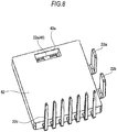
- Fig. 8 is a perspective view of a power module 62 of Fig. 7 .
- Fig. 9 is a perspective view of a major portion of the power module 62 when the motor terminal 13 is in proximity to an opening 62a before the motor terminal 13 is fixed in a state of being press-fit to a motor connection terminal 45.
- a configuration of the power module 62 of the electric drive unit 200 of the second embodiment is different from the configuration of the power module 21 described in the first embodiment above. Also, because the power modules are changed, a shape of a frame 63 is different from the shape of the frame 30 described in the first embodiment above. The rest of the configuration is the same as the electric drive unit 100 of the first embodiment above, and a detailed description is omitted herein.
- the power module 62 is provided with the opening 62a in which the motor terminal 13 as the first terminal is inserted.
- a module motor connection terminal 22e which is the lead frame 22, is positioned and fixed on the inner side of the opening 62a.
- the opening portion 62a is of a tapered shape by which the cross section of the opening 62a becomes gradually narrower from the side from which the motor terminal 13 is inserted toward the module motor connection terminal 22e.
- the motor terminal 13 is fixed in a press-fit state by sandwiching the module motor connection terminal 22e and the both terminals are electrically connected. Hence, the module motor connection terminals 22e are formed integrally with the motor connection terminals 45 as the second terminal. The motor connection terminals 45 are therefore integrally-molded with the power module 62.
- the frame 63 is formed by insert-molding the plurality of conductive plates 33 electrically connected to module power terminals 22a and 22b of the power modules 62, the coil 40, the capacitor 41, and various connectors (power connector 37, signal connector 38, torque sensor connector 39) with insulating resin.
- the electric drive unit 200 further includes, as are shown in Fig. 7 through Fig. 9 , the semiconductor modules (power modules 62) formed by encapsulating the semiconductor switching elements (FETs 23a and 23b) in mold resin.
- the power module 62 is provided with the opening 62a in which the motor terminal (first terminal) 13 is inserted and the motor connection terminal (second terminal) 45 is positioned and fixed on the inner side of the opening 62a.
- a wiring pattern is provided to the lead frame of the power module and is generally exposed to the outside of the power module.
- the module motor connection terminal 22e of the lead frame 22 is positioned and fixed on the inner side of the opening 62a in the power module 62. Hence, the module motor connection terminal 22e is not exposed to the outside and an amount of used material of the lead frame 22 is reduced comparably. The cost can be thus reduced.
- the motor connection terminal 45 is formed on the lead frame 22 as the module motor connection terminal 22e. Hence, it is not necessary to prepare the motor connection terminals 34 as components separate from the module motor connection terminals 22c as in the first embodiment above. The number of components can be thus reduced in comparison with a case in the first embodiment above. In addition, because a work to connect the motor connection terminal 34 and the module motor connection terminals 22c is not necessary, assembly man-hours are reduced, too. Hence, the number of components and the assembly man-hours are reduced and the cost can be reduced.
- the motor connection terminals 45 are integrally molded with the power module 62. Hence, the both ends of the motor connection terminal 45, which is the lead frame 22, are fixed with the mold resin when the power module 62 is formed by encapsulating the FETs 23a and 23b, which are the semiconductor switching elements, in the mold resin. Hence, a load applied to the motor connection terminals 45 during the press-fitting when the motor terminals 13 are fixed in a state of being press-fit to the motor connection terminals 45 is applied uniformly without concentrating to any point. Also, a load received by the motor connection terminals 45 can be received by the entire power modules 62 via the mold resin. Hence, deformation and damage of the motor connection terminals 45 can be prevented. The reliability of the electric drive unit is thus enhanced.
- the position of the motor connection terminals 45 is fixed when the motor connection terminals 45 are integrally molded with the power modules 62. Hence, position gap of the motor connection terminals 45 becomes smaller, which allows the motor terminals 13 to sandwich the motor connection terminals 45 in a reliable manner. Ease of assembly of the electric drive unit is thus enhanced.
- the heat sink 35 is located further on the opposite side to the electric motor 1 than the frame 63 and the power modules 62 are fixed in close contact to the heat sink 35 on the side of the electric motor 1 via the ceramic plate.
- the frame 63 is fixed with screws (not shown) to the heat sink 35 on the surface to which the power modules 62 are fixed. By tightening the screws, the frame 63 is fixed to the heat sink 35 in a state of being pressed against the heat sink 35.
- the opening 62a is of a tapered shape by which the cross section of the opening 62a becomes gradually narrower from the side from which the motor terminal 13 is inserted toward the motor connection terminal 45. Hence, when the motor terminal 13 is inserted into the opening 62a, the motor terminal 13 is guided to be positioned at the position at which the motor connection terminal 45 is present. The motor terminal 13 is therefore allowed to sandwich the motor connection terminal 45 along the taper of the opening 62a. Ease of assembly of the electric drive unit is thus enhanced.
- the frame 63 is provided with the guide portions 31 in which the motor terminals 13 are inserted.
- the motor terminals as the first terminal extend parallel to the axial direction of the rotation shaft from the electric motor toward the control apparatus and are fixed in a state of being press-fit to the motor connection terminals as the second terminal.
- the motor connection terminals as the second terminal are insert-molded in the frame or positioned and fixed on the inner side of the openings in the power modules.
- the frame and the power modules are inside the control apparatus at a position relatively remote from the electric motor.
- the motor terminals are sufficiently long relatively to the sectional area. Accordingly, when a load is applied to the motor terminals of a long column shape during the press-fitting of the motor terminals and the motor connection terminals, the motor terminals may possibly undergo deformation by buckling or the like.
- the motor terminals are made shorter by positioning and fixing an insulating member to the electric motor side of a housing that connects the electric motor and the control apparatus and by fixing the motor connection terminals to the housing via the insulating member.
- the motor terminals 13 undergo deformation by buckling or the like less frequently. It thus becomes possible to provide an electric drive unit with enhanced reliability.
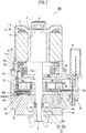
- FIG. 10 is a cross section of the electric drive unit 300 according to the third embodiment of the invention.
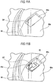
- Fig. 11 is a perspective view of a major portion of a housing 66 of Fig. 10 .
- Fig. 11A is a perspective view of a major portion of a power module 64 in the vicinity of a module motor connection terminal 22f.
- Fig. 11B is a perspective view of the major portion after a motor connection terminal 46 is welded to the module motor connection terminal 22f of Fig. 11A .
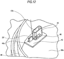
- Fig. 12 is a perspective view of a major portion of the housing 66 before the electric motor 1 and the control apparatus 20 are connected in the electric drive unit 300 of Fig. 10 .
- Fig. 13 is a perspective view of a major portion of an insulating member 42 when the motor terminal 13 is in proximity to a guide portion 43 before the motor terminal 13 is fixed in a state of press-fit to the motor connection terminal 46.
- the position of the motor connection terminals 46 of the electric drive unit 300 of the third embodiment is different from the positions of the motor connection terminals (34 and 45) described in the first and second embodiments above. Also, because the position of the motor connection terminals 46 is changed, shapes of the housing 66, the power modules 64, and a frame 65 are also different from the shapes of the housing 36, the power modules (21 and 62), and the frames (30 and 63) described in the first and second embodiments above. The rest of the configuration is the same as those of the electric drive units (100 and 200) of the first and second embodiments above, and a detailed description is omitted herein.
- a plate 66a perpendicular to a direction of the rotation shaft 2 of the electric motor 1 is integrally molded with the housing 66.
- the plate 66a is provided with a through-hole 66b through which the rotation shaft 2 passes and through-holes 66c in which insulating members 42 is fixed described below in a press-fit state when the electric motor 1 and the control apparatus 20 are connected.
- the module motor connection terminal 22f extends toward the side of the electric motor 1 of the housing 66 by passing through the through-hole 65a provided to the frame 65.
- the insulating members 42 are, for example, a member made of insulating resin. As is shown in Fig. 12 , the insulating member 42 is positioned on the side of the electric motor 1 of the housing 66 and, as has been described, fixed in a state of being press-fit to the through-hole 66c provided to the housing 66.
- the insulating member 42 is provided with a flange 42a serving as a stopper that suppresses movements of the insulating member 42 itself toward the control apparatus 20.
- the insulating member 42 is provided with a guide portion 43 made of insulating resin and having an insertion hole 43a in which the motor terminal 13 is inserted so as to guide the motor terminal 13 to allow the slit 13a in the motor terminal 13 to sandwich the motor connection terminal 46.
- the insertion hole 43a is of a tapered shape by which an axial cross section of the guide portion 43 becomes gradually narrower with respect to the axial direction from the side of the electric motor 1 (inlet) toward the side of the control apparatus 20 (outlet). Hence, a position of the motor terminal 13 is corrected as the motor terminal 13 passes through the insertion hole 43a. The motor terminal 13 can be thus guided to the position at which the motor connection terminal 46 is present.
- the insulating member 42 is formed by insert-molding the motor connection terminals 46.
- the motor connection terminal 46 is formed on a plane perpendicular to the rotation shaft 2 and a connection portion 46a exposed from the insulating member 42 is formed by bending one end in the shape of a capital L. As is shown in Fig. 11B , the connection portion 46a and the module motor connection terminal 22f are connected by joining means, such as welding.
- the electric drive unit 300 further includes the housing 66 disposed on the axis line of the rotation shaft 2 and connecting the electric motor 1 and the control apparatus 20.
- the insulating members 42 are positioned and fixed to the housing 66 on the side of the electric motor 1 and the motor connection terminals (second terminal) 46 are fixed to the housing 66 via the insulating members 42.
- the insulating members 42 are positioned between the electric motor 1 and the control apparatus 20, that is, on the side of the electric motor 1 of the housing 66 that is positioned on the side of the electric motor 1 of the control apparatus 20.
- the motor connection terminals 46 are fixed to the housing 66 via the insulating members 42.
- the housing 66 is positioned between the electric motor 1 and the control apparatus 20 and positioned on the side closer to the electric motor 1 than the frame 65 and the power module 64.
- the motor connection terminals 46 fixed to the housing 66 are also positioned on the side of the electric motor 1. Accordingly, the motor terminals (first terminal) 13 extending parallel to the axial direction of the rotation shaft 2 from the electric motor 1 toward the control apparatus 20 becomes shorter. Hence, the motor terminals 13 undergo deformation by buckling or the like less frequently. It thus becomes possible to provide an electric drive unit with enhanced reliability.
- the motor terminals 13 are formed by press working a plate material of special copper alloy having higher heat-resistant creep characteristics than the motor connection terminals 46, an amount of used special copper alloy is reduced because the motor terminals 13 become shorter. The cost of the electric drive unit is thus reduced.
- the insulating members 42 are fixed in a state of being press-fit to the through-holes 66c provided to the housing 66, the position of the motor connection terminals 46 fixed via the insulating members 42 is fixed as well. Hence, position gap of the motor connection terminals 46 becomes smaller, which allows the motor terminals 13 to sandwich the motor connection terminals 46 in a reliable manner. Ease of assembly of the electric drive unit is thus enhanced.
- the insulating members 42 are provided with the flanges 42a serving as a stopper that suppresses movements of the insulating members 42 per se toward the control apparatus 20.
- the motor connection terminals 46 are fixed to the housing 66 via the insulating members 42 and the insulating members 42 are provided with the guide portions 43 in which the motor terminals 13 are inserted.
- the guide portions 43 serve as a guide that corrects a position of the motor terminals 13 to be the position at which the motor connection terminals 46 are present.
- the motor terminals 13 are therefore guided by the guide portions 43 and allowed to sandwich the motor connection terminals 46. Ease of assembly of the electric drive unit is thus enhanced.
- the third embodiment has described a case where the guide portions 43 are formed as components separate from the insulating members 42. It should be appreciated, however, that because both of the insulating members 42 and the guide portions 43 are molded from insulating resin, the both components can be integrally molded into a single piece. By integrally molding the insulating members 42 and the guide portions 43 from insulating resin, assembly man-hours are reduced. The cost of the electric drive unit can be thus reduced.
- the positional accuracy of the guide portions 43 is enhanced in comparison with a case where the both components are formed separately. Hence, not only is ease of assembly of the electric drive unit further enhanced, but the reliably of the electric drive unit is also enhanced. Further, in the third embodiment, the guide portions 43 are formed, as is shown in Fig. 13 , so as to cover the periphery of the motor terminals 13. Hence, an insulating property can be ensured. The reliability of the electric drive unit is thus enhanced further.
- the motor connection terminals 46 are insert-molded in the insulating members 42 made of insulating resin. Hence, the both ends of the motor connection terminals 46 are fixed with the insulating resin when the insulating members 42 are formed. Hence, a load applied to the motor connection terminals 46 during the press-fitting when the motor terminals 13 are fixed in a state of being press-fit to the motor connection terminals 46 is applied uniformly without concentrating to any point. Also, a load received by the motor connection terminals 46 can be received by the entire insulating members 42. Hence, deformation and damage of the motor connection terminals 46 can be prevented. The reliability of the electric drive unit is thus enhanced.
- the position of the motor connection terminals 46 is fixed when the motor connection terminals 46 are insert-molded in the insulating members 42. Hence, position gap of the motor connection terminals 46 becomes smaller, which allows the motor terminals 13 to sandwich the motor connection terminals 46 in a reliable manner. Ease of assembly of the electric drive unit is thus enhanced. Moreover, because the assembly man-hours are reduced by insert-molding the motor connection terminals 46 in the insulating member 42, the cost can be reduced.
- the first through third embodiments above have described the electric drive units (100, 200, and 300, respectively) employed in an electric power steering apparatus.
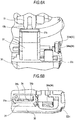
- a fourth embodiment will describe, using Fig. 14 and Fig. 15 , an electric power steering apparatus to which the electric drive unit 101 of the first embodiment above is attached as one of the electric power steering apparatuses to which the electric drive units (100, 200, and 300) of the first through third embodiments are attached.
- Fig. 14 is a cross section of the electric power steering apparatus according to the fourth embodiment of the invention.
- the electric power steering apparatus includes a speed reducing device 14 that reduces a rotating speed of the electric motor 1 and is attached to the electric drive unit 101 of the first embodiment above on the side of the control apparatus 20. More specifically, the electric drive unit 101 is fixed to the speed reducing device 14 with screws (not shown) via the heat sink 35 of the control apparatus 20.
- the speed reducing device 14 has a gear case 15 to which the heat sink 35 of the control apparatus 20 is attached, a worm gear 16, which is a reduction gear that reduces rotations of the rotation shaft 2 and provided inside the gear case 15, and a worm wheel 17 meshed with the worm gear 16.
- a coupling 18 is fixed to the worm gear 16 at an end on the side of the rotation shaft 2. When the coupling 18 and the coupling 7 are coupled, a torque is transmitted from the electric motor 1 to the worm gear 16.
- the electric power steering apparatus has the speed reducing device 14 that reduces a rotating speed of the electric motor 1 and is attached to the heat sink 35 in the control apparatus 20 of the electric drive unit 101.
- heat generated from heat-generating components (coil 40, capacitor 41, and power modules 21) forming the control apparatus 20 (drive portion 61) is first released to the heat sink 35 and then further to the speed reducing apparatus 14.
- Heat generated from the control apparatus 20 is therefore released from the speed reducing device 14.
- a heat-releasing property of the electric power steering apparatus is enhanced. Accordingly, because a temperature rise when heat is generated in the control apparatus 20 is suppressed, it becomes possible to provide an electric power steering apparatus with enhanced reliability.
- the fourth embodiment has described a case where the speed reducing device 14 is attached to the heat sink 35 located on the side of the control apparatus 20 of the electric drive unit 101 of the first embodiment above. It should be appreciated, however, that the speed reducing device 14 may be attached on the side of the electric motor 1, which is the opposite side to the control apparatus 20.
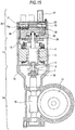
- Fig. 15 is a cross section of another example of the electric power steering apparatus according to the fourth embodiment of the invention. As is shown in Fig. 15 , the electric power steering apparatus is formed by attaching the speed reducing device 14 to the electric drive unit 102 of the first embodiment above on the side of the electric motor 1. More specifically, the electric drive unit 102 is fixed to the speed reducing device 14 with screws (not shown) via the yoke 6 of the electric motor 1.
- the speed reducing device 14 that reduces a rotating speed of the electric motor 1 is attached to the yoke 6 in the electric motor 1 of the electric drive unit 102.
- the electric motor 1 having a heavy weight is therefore sandwiched between the control apparatus 20 and the speed recuing device 14. Owing to this configuration, a durability performance against vibrations of the electric motor 1, that is, vibration resistance is increased. It thus becomes possible to provide an electric power steering apparatus with enhanced reliability.
- the electric motor 1 is a brushless motor. It should be appreciated, however, that the invention is not limited to this case, and the electric motor 1 may instead be an induction motor or a switched reluctance motor (SR motor).
- SR motor switched reluctance motor
- the FET 23b forming a motor relay serving as switching means for passing and interrupting a motor current IM to be supplied to the electric motor 1 is mounted on the power modules (21, 62, and 65). It should be appreciated, however, that a configuration that omits the FET 23b is also applicable.
- the shunt resistor 24 is integrally molded with the power modules (21, 62, and 65) as a forming component. It should be appreciated, however, that the shunt resistor 24 may be formed as a component separate from the power modules (21, 62, and 65).
- a current detection circuit adopting a low-side method by which the shunt resistor 24 is interposed between the three-phase bridge circuit and the earth ground. It should be appreciated, however, that it is also possible to use, as another configuration, a current detection circuit adopting so-called a high-side method by which the shunt resistor is interposed between the high-potential side of the power supply that supplies the motor current IM to the electric motor 1 and the three-phase bridge circuit. Further, the detection means of the motor current IM may be formed of a component other than the shunt resistor 24.
Claims (16)
- Elektrische Antriebseinheit (100), umfassend einen Elektromotor (1) und eine Steuerungsvorrichtung (20), die an einer Achslinie einer Welle (2) des Elektromotors angeordnet ist und ein Antreiben des Elektromotors steuert, wobei
die Steuerungsvorrichtung (20) beinhaltet:einen Antriebsabschnitt (61), der den elektrischen Motor antreibt und aus Halbleiterschaltungselementen (23), die einen Strom des elektrischen Motors schalten, und passiven Elementen (40) (41), die elektrisch mit den Schaltungselementen verbunden sind, ausgebildet ist, undeinen Rahmen (30, 63, 65), in welchem mehrere leitende Platten (33), die mit jeweiligen Anschlüssen der passiven Elemente verbunden werden, mit einem Isolationskunststoff umspritzt sind und an welchem die passiven Elemente bereitgestellt sind;der Elektromotor oder die Steuerungsvorrichtung einen ersten Anschluss (13, 13U, 13V, 13W) aufweist, der sich parallel zu einer Achsrichtung der Welle zu dem anderen mit einem Schlitz (13a) erstreckt, der an dem ersten Anschluss an einem Ende an einer Seite des anderen bereitgestellt ist;
das andere einen zweiten Anschluss (34, 34U, 34V, 34W, 45, 46) aufweist, der an einer Linie bereitgestellt ist, die sich von dem ersten Anschluss erstreckt, und elektrisch mit dem zweiten Anschluss verbunden ist, und
der erste Anschluss in einem Zustand, in dem dieser an den zweiten Anschluss angepresst ist, fixiert ist, indem dem Schlitz ermöglicht wird, den zweiten Anschluss von zwei Seiten zu umgeben,
dadurch gekennzeichnet, dass
der erste Anschluss aus einer Kupferlegierung hergestellt ist, die ein höheres wärmefestes Kriechverhalten als der zweite Anschluss aufweist,
und dass:der Rahmen mit einem Führungsabschnitt (31) bereitgestellt ist, in welchem der erste Anschluss eingeführt ist. - Elektrische Antriebseinheit nach Anspruch 1, dadurch gekennzeichnet, dass:mindestens die Spitzenenden des Schlitzes in dem ersten Anschluss in einer verjüngten Form sind.
- Elektrische Antriebseinheit nach Anspruch 1 oder 2, dadurch gekennzeichnet, dass:der erste Anschluss eine Endfläche (13e) senkrecht zu der Achslinie der Welle an einem Ende an einer Seite gegenüber einer Seite aufweist, an welcher der Schlitz bereitgestellt ist; undferner ein anliegendes Element (11) gegen die Endfläche anliegend beinhaltet ist.
- Elektrische Antriebseinheit nach einem der vorhergehenden Ansprüche, dadurch gekennzeichnet, dass:der erste Anschluss ein Motoranschluss des elektrischen Motors ist;ein Zwischenelement (12, 12U, 12V, 12W), das ein höheres wärmefestes Kriechverhalten als der Motoranschluss aufweist, ferner beinhaltet ist; undder Motoranschluss elektrisch mit einer Ankerwicklung (10) des elektrischen Motors über das Zwischenelement verbunden ist.
- Elektrische Antriebseinheit nach Anspruch 4, dadurch gekennzeichnet, dass:der elektrische Motor ferner einen Isolationshalter (11) beinhaltet, der einen Trägerabschnitt (11a) aufweist, welcher das Zwischenelement trägt; undder Motoranschluss an einer Seite radial weiter außen als der Trägerabschnitt liegt.
- Elektrische Antriebseinheit nach einem der Ansprüche 1 bis 5, dadurch gekennzeichnet, dass:der erste Anschluss (13) ein Motoranschluss des elektrischen Motors ist;der zweite Anschluss (45) ein Motorverbindungsanschluss der Steuerungsvorrichtung ist; undder Motorverbindungsanschluss in dem Rahmen (63) umspritzt ist.
- Elektrische Antriebseinheit nach einem der vorhergehenden Ansprüche, dadurch gekennzeichnet, dass:der Rahmen (63) eine Endfläche (13e) senkrecht zu der Achslinie der Welle an einer Seite weiter außen als der Führungsabschnitt (31) und an einem Ende an einer gegenüberliegenden Seite zu dem elektrischen Motor aufweist; undferner ein Trägerelement (11), das den Rahmen durch Anliegen an der Endfläche (13e) trägt, enthalten ist.
- Elektrische Antriebseinheit nach einem der vorhergehenden Ansprüche, dadurch gekennzeichnet, dass:der erste Anschluss (13) ein Motoranschluss des elektrischen Motors ist;der zweite Anschluss (45) ein Motorverbindungsanschluss der Steuerungsvorrichtung ist;ferner ein Halbleitermodul (62), das durch Einkapseln eines Halbleiterschaltungselements in einem gegossenen Kunststoff ausgebildet ist, enthalten ist;das Halbleitermodul eine Öffnung (62a) aufweist, in welcher der Motoranschluss eingeführt ist; undder Motorverbindungsanschluss an einer inneren Seite der Öffnung positioniert und fixiert ist.
- Elektrische Antriebseinheit nach Anspruch 8, dadurch gekennzeichnet, dass:der Motorverbindungsanschluss integral mit dem Halbleitermodul (62) gegossen ist.
- Elektrische Antriebseinheit nach einem der Ansprüche 8 und 9, dadurch gekennzeichnet, dass:die Steuerungsvorrichtung ferner einen Kühler (35) beinhaltet, durch welchen Wärme, die in dem Halbleitermodul generiert wird, abgegeben wird; unddas Halbleitermodul an dem Kühler durch Fixieren des Rahmens an dem Kühler in einem Zustand, in dem dieser gegen den Kühler gedrückt ist, fixiert ist.
- Elektrische Antriebseinheit nach einem der vorhergehenden Ansprüche, dadurch gekennzeichnet, dass:der erste Anschluss (13) ein Motoranschluss des elektrischen Motors ist;der zweite Anschluss (46) ein Motorverbindungsanschluss der Steuerungsvorrichtung ist;ferner ein Gehäuse (66), das an der Achslinie der Welle angeordnet ist und den elektrischen Motor und die Steuerungsvorrichtung verbindet, enthalten ist;ein Isolationselement (42) an dem Gehäuse an einer Seite des elektrischen Motors positioniert und fixiert ist; undder Motorverbindungsanschluss an dem Gehäuse durch das Isolationselement fixiert ist.
- Elektrische Antriebseinheit nach Anspruch 11, dadurch gekennzeichnet, dass:das Isolationselement (42) in einem Zustand fixiert ist, in dem es in ein Durchgangsloch, das an dem Gehäuse bereitgestellt ist, eingepresst ist.
- Elektrische Antriebseinheit nach Anspruch 11 oder 12, dadurch gekennzeichnet, dass:das Isolationselement (42) mit einem Führungsabschnitt (43) bereitgestellt ist, in welchem der Motoranschluss eingeführt ist.
- Elektrische Antriebseinheit nach einem der Ansprüche 11 bis 13, dadurch gekennzeichnet, dass:der Motorverbindungsanschluss in dem Isolationselement (42) umspritzt wird.
- Elektrische Antriebseinheit nach einem der Ansprüche 1 bis 14, dadurch gekennzeichnet, dass:eine Reduktionsvorrichtung (14) für eine Geschwindigkeit, welche eine Rotationsgeschwindigkeit des elektrischen Motors reduziert, an dem elektrischen Motor an einer Seite gegenüber der Steuerungsvorrichtung angebracht ist.
- Elektrische Antriebseinheit nach einem der Ansprüche 1 bis 14, dadurch gekennzeichnet, dass:eine Reduktionsvorrichtung (14) für eine Geschwindigkeit, welche eine Rotationsgeschwindigkeit des elektrischen Motors reduziert, an der Steuerungsvorrichtung an einer Seite gegenüber dem elektrischen Motor angebracht ist.
Applications Claiming Priority (2)
| Application Number | Priority Date | Filing Date | Title |
|---|---|---|---|
| JP2011198462 | 2011-09-12 | ||
| PCT/JP2011/075417 WO2013038572A1 (ja) | 2011-09-12 | 2011-11-04 | 電動式駆動装置 |
Publications (3)
| Publication Number | Publication Date |
|---|---|
| EP2757665A1 EP2757665A1 (de) | 2014-07-23 |
| EP2757665A4 EP2757665A4 (de) | 2015-10-14 |
| EP2757665B1 true EP2757665B1 (de) | 2017-03-01 |
Family
ID=47882830
Family Applications (1)
| Application Number | Title | Priority Date | Filing Date |
|---|---|---|---|
| EP11872253.7A Active EP2757665B1 (de) | 2011-09-12 | 2011-11-04 | Elektrische antriebsvorrichtung |
Country Status (6)
| Country | Link |
|---|---|
| US (1) | US9450476B2 (de) |
| EP (1) | EP2757665B1 (de) |
| JP (1) | JP5634610B2 (de) |
| CN (1) | CN103797691B (de) |
| IN (1) | IN2014CN02465A (de) |
| WO (1) | WO2013038572A1 (de) |
Cited By (1)
| Publication number | Priority date | Publication date | Assignee | Title |
|---|---|---|---|---|
| DE102018209152A1 (de) * | 2018-06-08 | 2019-12-12 | Continental Automotive Gmbh | Inverter und Elektromotorvorrichtung |
Families Citing this family (55)
| Publication number | Priority date | Publication date | Assignee | Title |
|---|---|---|---|---|
| WO2012153402A1 (ja) * | 2011-05-11 | 2012-11-15 | 三菱電機株式会社 | 電動パワーステアリング装置 |
| US9586615B2 (en) | 2012-01-25 | 2017-03-07 | Mitsubishi Electric Corporation | Electric power steering apparatus |
| JP6271968B2 (ja) * | 2012-12-28 | 2018-01-31 | 株式会社ミツバ | 電動モータおよび電動ポンプ |
| CA2895591C (en) | 2012-12-28 | 2020-08-25 | Masaki Ishizeki | Electric motor and electric pump |
| JP2015039283A (ja) * | 2013-04-02 | 2015-02-26 | アスモ株式会社 | 回転電機 |
| CA2816212A1 (en) * | 2013-05-17 | 2014-11-17 | Brandt Agricultural Products Ltd. | Electric mover for swing away conveyor |
| JP5490290B1 (ja) * | 2013-06-06 | 2014-05-14 | 三菱電機株式会社 | 電動パワーアシスト用モータ装置の給電部構造 |
| US9929614B2 (en) * | 2013-07-02 | 2018-03-27 | Nidec Corporation | Motor with integrated slot liner and bobbin with guides for conductor coils |
| JP6117661B2 (ja) * | 2013-09-19 | 2017-04-19 | 日立オートモティブシステムズ株式会社 | 電子制御装置 |
| US20160362127A1 (en) * | 2013-12-13 | 2016-12-15 | Nsk Ltd. | Electronic Controlling Unit, Electric Power Steering Device, and Vehicle |
| US10361603B2 (en) | 2013-12-16 | 2019-07-23 | Mitsubishi Electric Corporation | Mechanically and electrically integrated driving apparatus and manufacturing method therefor |
| US10211709B2 (en) * | 2014-03-26 | 2019-02-19 | Mitsubishi Electric Corporation | Electric power steering device |
| US10199902B2 (en) * | 2014-05-01 | 2019-02-05 | Mitsubishi Electric Corporation | Automotive controlling apparatus |
| US10367397B2 (en) | 2014-05-12 | 2019-07-30 | Mitsubishi Electric Corporation | Controller-integrated rotary electric machine and method for manufacturing the same |
| EP3162660B1 (de) * | 2014-06-27 | 2020-07-01 | Mitsubishi Electric Corporation | Integrierte elektrische servolenkvorrichtung und herstellungsverfahren dafür |
| WO2016075789A1 (ja) * | 2014-11-13 | 2016-05-19 | 三菱電機株式会社 | 制御ユニットおよびこれを用いた電動パワーステアリング装置 |
| JP6351750B2 (ja) * | 2014-11-14 | 2018-07-04 | 三菱電機株式会社 | 制御ユニットおよびこれを用いた電動パワーステアリング装置 |
| DE102015201397A1 (de) * | 2015-01-28 | 2016-07-28 | Zf Friedrichshafen Ag | Leistungssteuerung für eine Drehfeldmaschine |
| JP6107847B2 (ja) * | 2015-02-10 | 2017-04-05 | 日本精工株式会社 | 端子接続構造、モータ、アクチュエータ、電動パワーステアリング装置および車両 |
| JP5951067B1 (ja) * | 2015-04-10 | 2016-07-13 | 三菱電機株式会社 | 電動パワーステアリング装置 |
| US10734869B2 (en) * | 2015-04-27 | 2020-08-04 | Mitsubishi Electric Corporation | Control device with semiconductor module having bent latch, control, power supply and motor control terminals |
| DE112016003891T5 (de) | 2015-08-27 | 2018-05-09 | Nidec Corporation | Motor |
| US10404136B2 (en) * | 2015-10-14 | 2019-09-03 | Black & Decker Inc. | Power tool with separate motor case compartment |
| JP6499988B2 (ja) * | 2016-03-09 | 2019-04-10 | 日立オートモティブシステムズ株式会社 | 電動駆動装置及び電動パワーステアリング装置 |
| JP6671209B2 (ja) * | 2016-03-28 | 2020-03-25 | Ntn株式会社 | 電動アクチュエータ |
| WO2018030480A1 (ja) * | 2016-08-12 | 2018-02-15 | 日本電産株式会社 | モータ |
| JP6595436B2 (ja) * | 2016-10-25 | 2019-10-23 | オムロンオートモーティブエレクトロニクス株式会社 | 回路一体型モータ |
| DE102016121119A1 (de) | 2016-11-04 | 2018-05-09 | Nidec Corporation | Sammelschieneneinheit für einen Elektromotor |
| DE102017101739A1 (de) * | 2017-01-30 | 2018-08-02 | Ebm-Papst St. Georgen Gmbh & Co. Kg | Baukastensystem |
| JP6702212B2 (ja) * | 2017-01-31 | 2020-05-27 | 株式会社デンソー | 駆動装置 |
| JP2018125940A (ja) * | 2017-01-31 | 2018-08-09 | 株式会社デンソー | 駆動装置 |
| KR101896060B1 (ko) * | 2017-02-15 | 2018-09-06 | 주식회사 만도 | 자동차 조향장치의 전자제어장치 |
| CN110431734B (zh) * | 2017-03-27 | 2022-09-16 | 三菱电机株式会社 | 电动机和空调装置 |
| JP6885156B2 (ja) * | 2017-03-31 | 2021-06-09 | 三菱自動車エンジニアリング株式会社 | 高電圧機器 |
| JP6847763B2 (ja) * | 2017-05-18 | 2021-03-24 | 株式会社マキタ | 電動工具 |
| CN108945085A (zh) * | 2017-05-19 | 2018-12-07 | 上海海拉电子有限公司 | 一种电动助力转向系统 |
| FR3068179A1 (fr) * | 2017-06-22 | 2018-12-28 | Valeo Systemes De Controle Moteur | Dispositif de connexion electrique comportant une embase de connexion et un dispositif de guidage |
| JP6939185B2 (ja) * | 2017-07-25 | 2021-09-22 | 日本電産トーソク株式会社 | 電動アクチュエータ |
| JP6844710B2 (ja) * | 2017-09-28 | 2021-03-17 | 日本電産トーソク株式会社 | 電動アクチュエータ |
| JP7044799B2 (ja) | 2017-10-13 | 2022-03-30 | 三菱電機株式会社 | 電動パワーステアリング装置 |
| US10998797B2 (en) * | 2017-12-19 | 2021-05-04 | Tti (Macao Commercial Offshore) Limited | Electric motor assembly including end cap having heat sink for heat-generating electrical component |
| JP6593815B2 (ja) * | 2018-02-21 | 2019-10-23 | 三菱電機株式会社 | 電動パワーステアリング装置 |
| JP2019161773A (ja) | 2018-03-09 | 2019-09-19 | 株式会社デンソー | 回転電機 |
| US11015564B2 (en) * | 2018-04-24 | 2021-05-25 | GM Global Technology Operations LLC | Starter for an internal combustion engine |
| US10886817B2 (en) * | 2018-04-24 | 2021-01-05 | GM Global Technology Operations LLC | On-axis brushless starter assembly |
| JP7110872B2 (ja) * | 2018-09-26 | 2022-08-02 | 日本電産トーソク株式会社 | 電動アクチュエータ |
| CN216406912U (zh) * | 2018-10-26 | 2022-04-29 | 博格华纳公司 | 旋转机器 |
| FR3091062B1 (fr) * | 2018-12-20 | 2023-05-26 | Valeo Equip Electr Moteur | Ensemble d’interconnexion pour machine électrique tournante et machine électrique tournante |
| US11767053B2 (en) * | 2018-12-27 | 2023-09-26 | Hitachi Astemo, Ltd. | Electronic control device and electric power steering device |
| DE102019102318A1 (de) * | 2019-01-30 | 2020-07-30 | Nidec Gpm Gmbh | Pumpe aufweisend einen Elektromotor mit Steckeranbindung in Form eines Zwischenringes |
| JP7160012B2 (ja) * | 2019-10-03 | 2022-10-25 | 株式会社デンソー | 電子制御装置 |
| JP6955047B2 (ja) * | 2020-03-31 | 2021-10-27 | 本田技研工業株式会社 | 電力制御ユニット |
| WO2021223875A1 (en) * | 2020-05-08 | 2021-11-11 | HELLA GmbH & Co. KGaA | Electronic control unit and electric power steering system |
| US11658545B2 (en) | 2020-06-19 | 2023-05-23 | Snap-On Incorporated | Brushless direct current motor end cap |
| WO2023095217A1 (ja) * | 2021-11-24 | 2023-06-01 | 株式会社ジェイテクト | モータ装置およびモータ制御装置 |
Family Cites Families (23)
| Publication number | Priority date | Publication date | Assignee | Title |
|---|---|---|---|---|
| DE2146893C3 (de) * | 1971-09-20 | 1974-02-07 | Siemens Ag, 1000 Berlin U. 8000 Muenchen | Kollektorloser Gleichstrommotor mit einer durch Hall generatoren gesteuerten, aus Halbleiterschaltelementen aufgebauten Kommutierungseinrichtung |
| US4926075A (en) * | 1987-12-28 | 1990-05-15 | Makita Electric Works, Ltd. | Electric motor brush assembly adaptable to different stators |
| JPH04128069U (ja) | 1991-05-14 | 1992-11-20 | 自動車電機工業株式会社 | ワイパモータ |
| US5825107A (en) * | 1997-06-13 | 1998-10-20 | General Electric Company | Drive package for a dynamoelectric machine |
| KR100356894B1 (ko) * | 1997-10-01 | 2002-10-19 | 카야바 고교 가부시기가이샤 | 전동 파워 스티어링 장치의 전동 모터 |
| US5939807A (en) * | 1997-12-16 | 1999-08-17 | Reliance Electric Industrial Company | Cap mounted drive for a brushless DC motor |
| JP3774624B2 (ja) * | 2000-10-18 | 2006-05-17 | 三菱電機株式会社 | 電動パワーステアリング装置 |
| JP2002252958A (ja) | 2001-02-23 | 2002-09-06 | Mitsubishi Electric Corp | ブラシレスdcモータ |
| JP3593102B2 (ja) * | 2002-01-08 | 2004-11-24 | 三菱電機株式会社 | 電動パワーステアリング装置 |
| FR2865981B1 (fr) * | 2004-02-06 | 2006-04-21 | Valeo Systemes Dessuyage | Moto-reducteur notamment pour mecanisme d'essuie-glace de vehicule automobile |
| US20090079280A1 (en) * | 2005-04-08 | 2009-03-26 | Takahiro Terauchi | Motor Apparatus |
| JP4502912B2 (ja) * | 2005-09-16 | 2010-07-14 | 三菱電機株式会社 | 回転電機およびその製造方法 |
| DE102007006859A1 (de) * | 2007-02-12 | 2008-08-14 | Siemens Ag | Kontaktierung |
| WO2008102482A1 (ja) * | 2007-02-19 | 2008-08-28 | Mitsubishi Electric Corporation | モータの端子構造 |
| JP4623125B2 (ja) | 2008-04-07 | 2011-02-02 | 三菱電機株式会社 | 電動パワ−ステアリング用電動モ−タ装置および電動パワーステアリング装置 |
| JP5091038B2 (ja) * | 2008-04-18 | 2012-12-05 | アスモ株式会社 | モータ構造 |
| EP2623394B1 (de) * | 2008-07-16 | 2014-08-20 | Mitsubishi Electric Corporation | Elektrische Servolenkvorrichtung und Elektromotor mit integrierter Steuerungsvorrichtung |
| JP5476791B2 (ja) * | 2009-05-13 | 2014-04-23 | 日本電産株式会社 | モータの給電構造及びモータ |
| JP2011035984A (ja) * | 2009-07-30 | 2011-02-17 | Mitsubishi Electric Corp | 電動モ−タ装置 |
| JP5410194B2 (ja) * | 2009-08-07 | 2014-02-05 | 株式会社デンソー | 駆動回路内蔵型モータ |
| JP4772139B2 (ja) * | 2009-08-07 | 2011-09-14 | 三菱電機株式会社 | 電動パワーステアリング装置用モータ装置 |
| JP2011114979A (ja) * | 2009-11-27 | 2011-06-09 | Panasonic Electric Works Co Ltd | モータ、このモータを用いたポンプ及びこのポンプを用いた液体循環装置 |
| JP5039171B2 (ja) * | 2010-05-11 | 2012-10-03 | 三菱電機株式会社 | 電動式駆動装置およびその電動式駆動装置を搭載した電動式パワーステアリング装置 |
-
2011
- 2011-11-04 IN IN2465CHN2014 patent/IN2014CN02465A/en unknown
- 2011-11-04 WO PCT/JP2011/075417 patent/WO2013038572A1/ja active Application Filing
- 2011-11-04 EP EP11872253.7A patent/EP2757665B1/de active Active
- 2011-11-04 CN CN201180073409.0A patent/CN103797691B/zh active Active
- 2011-11-04 US US14/122,788 patent/US9450476B2/en active Active
- 2011-11-04 JP JP2013533454A patent/JP5634610B2/ja active Active
Non-Patent Citations (1)
| Title |
|---|
| None * |
Cited By (1)
| Publication number | Priority date | Publication date | Assignee | Title |
|---|---|---|---|---|
| DE102018209152A1 (de) * | 2018-06-08 | 2019-12-12 | Continental Automotive Gmbh | Inverter und Elektromotorvorrichtung |
Also Published As
| Publication number | Publication date |
|---|---|
| CN103797691B (zh) | 2016-12-21 |
| EP2757665A4 (de) | 2015-10-14 |
| US20140091683A1 (en) | 2014-04-03 |
| IN2014CN02465A (de) | 2015-08-07 |
| JP5634610B2 (ja) | 2014-12-03 |
| EP2757665A1 (de) | 2014-07-23 |
| US9450476B2 (en) | 2016-09-20 |
| JPWO2013038572A1 (ja) | 2015-03-23 |
| WO2013038572A1 (ja) | 2013-03-21 |
| CN103797691A (zh) | 2014-05-14 |
Similar Documents
| Publication | Publication Date | Title |
|---|---|---|
| EP2757665B1 (de) | Elektrische antriebsvorrichtung | |
| EP2892130B1 (de) | Elektrische antriebsvorrichtung und verfahren zur herstellung der elektrischen antriebsvorrichtung | |
| EP2549627B1 (de) | Elektrische antriebsvorrichtung und stromlenkungsvorrichtung mit dieser darin montierten vorrichtung | |
| JP5719524B2 (ja) | 電動装置 | |
| EP2571147B1 (de) | Elektrische antriebsvorrichtung und elektrische servolenkung damit | |
| US7021418B2 (en) | Electric power steering apparatus | |
| EP2371673B1 (de) | Elektrische Ansteuervorrichtung | |
| KR101206158B1 (ko) | 전동식 파워 스티어링 장치 | |
| US7445081B2 (en) | Electric power steering apparatus | |
| JP5927836B2 (ja) | 駆動装置 | |
| EP2634066B1 (de) | Vorrichtung zur steuerung des antriebs eines motors für eine elektrische servolenkvorrichtung | |
| JP3614380B2 (ja) | 電動式パワーステアリング装置 | |
| JP6983338B2 (ja) | 電動駆動装置 | |
| CN111801266B (zh) | 电动驱动装置以及电动动力转向装置 |
Legal Events
| Date | Code | Title | Description |
|---|---|---|---|
| PUAI | Public reference made under article 153(3) epc to a published international application that has entered the european phase |
Free format text: ORIGINAL CODE: 0009012 |
|
| 17P | Request for examination filed |
Effective date: 20140109 |
|
| AK | Designated contracting states |
Kind code of ref document: A1 Designated state(s): AL AT BE BG CH CY CZ DE DK EE ES FI FR GB GR HR HU IE IS IT LI LT LU LV MC MK MT NL NO PL PT RO RS SE SI SK SM TR |
|
| DAX | Request for extension of the european patent (deleted) | ||
| RA4 | Supplementary search report drawn up and despatched (corrected) |
Effective date: 20150910 |
|
| RIC1 | Information provided on ipc code assigned before grant |
Ipc: B62D 5/04 20060101ALI20150904BHEP Ipc: H02K 5/04 20060101ALI20150904BHEP Ipc: H02K 5/10 20060101ALI20150904BHEP Ipc: H01R 13/10 20060101ALI20150904BHEP Ipc: H02K 5/22 20060101AFI20150904BHEP |
|
| GRAP | Despatch of communication of intention to grant a patent |
Free format text: ORIGINAL CODE: EPIDOSNIGR1 |
|
| INTG | Intention to grant announced |
Effective date: 20160920 |
|
| GRAS | Grant fee paid |
Free format text: ORIGINAL CODE: EPIDOSNIGR3 |
|
| GRAA | (expected) grant |
Free format text: ORIGINAL CODE: 0009210 |
|
| AK | Designated contracting states |
Kind code of ref document: B1 Designated state(s): AL AT BE BG CH CY CZ DE DK EE ES FI FR GB GR HR HU IE IS IT LI LT LU LV MC MK MT NL NO PL PT RO RS SE SI SK SM TR |
|
| REG | Reference to a national code |
Ref country code: GB Ref legal event code: FG4D |
|
| REG | Reference to a national code |
Ref country code: CH Ref legal event code: EP Ref country code: AT Ref legal event code: REF Ref document number: 872385 Country of ref document: AT Kind code of ref document: T Effective date: 20170315 |
|
| REG | Reference to a national code |
Ref country code: IE Ref legal event code: FG4D |
|
| REG | Reference to a national code |
Ref country code: DE Ref legal event code: R096 Ref document number: 602011035580 Country of ref document: DE |
|
| REG | Reference to a national code |
Ref country code: NL Ref legal event code: MP Effective date: 20170301 |
|
| REG | Reference to a national code |
Ref country code: LT Ref legal event code: MG4D |
|
| REG | Reference to a national code |
Ref country code: AT Ref legal event code: MK05 Ref document number: 872385 Country of ref document: AT Kind code of ref document: T Effective date: 20170301 |
|
| PG25 | Lapsed in a contracting state [announced via postgrant information from national office to epo] |
Ref country code: FI Free format text: LAPSE BECAUSE OF FAILURE TO SUBMIT A TRANSLATION OF THE DESCRIPTION OR TO PAY THE FEE WITHIN THE PRESCRIBED TIME-LIMIT Effective date: 20170301 Ref country code: GR Free format text: LAPSE BECAUSE OF FAILURE TO SUBMIT A TRANSLATION OF THE DESCRIPTION OR TO PAY THE FEE WITHIN THE PRESCRIBED TIME-LIMIT Effective date: 20170602 Ref country code: LT Free format text: LAPSE BECAUSE OF FAILURE TO SUBMIT A TRANSLATION OF THE DESCRIPTION OR TO PAY THE FEE WITHIN THE PRESCRIBED TIME-LIMIT Effective date: 20170301 Ref country code: NO Free format text: LAPSE BECAUSE OF FAILURE TO SUBMIT A TRANSLATION OF THE DESCRIPTION OR TO PAY THE FEE WITHIN THE PRESCRIBED TIME-LIMIT Effective date: 20170601 Ref country code: HR Free format text: LAPSE BECAUSE OF FAILURE TO SUBMIT A TRANSLATION OF THE DESCRIPTION OR TO PAY THE FEE WITHIN THE PRESCRIBED TIME-LIMIT Effective date: 20170301 |
|
| PG25 | Lapsed in a contracting state [announced via postgrant information from national office to epo] |
Ref country code: RS Free format text: LAPSE BECAUSE OF FAILURE TO SUBMIT A TRANSLATION OF THE DESCRIPTION OR TO PAY THE FEE WITHIN THE PRESCRIBED TIME-LIMIT Effective date: 20170301 Ref country code: SE Free format text: LAPSE BECAUSE OF FAILURE TO SUBMIT A TRANSLATION OF THE DESCRIPTION OR TO PAY THE FEE WITHIN THE PRESCRIBED TIME-LIMIT Effective date: 20170301 Ref country code: AT Free format text: LAPSE BECAUSE OF FAILURE TO SUBMIT A TRANSLATION OF THE DESCRIPTION OR TO PAY THE FEE WITHIN THE PRESCRIBED TIME-LIMIT Effective date: 20170301 Ref country code: BG Free format text: LAPSE BECAUSE OF FAILURE TO SUBMIT A TRANSLATION OF THE DESCRIPTION OR TO PAY THE FEE WITHIN THE PRESCRIBED TIME-LIMIT Effective date: 20170601 Ref country code: LV Free format text: LAPSE BECAUSE OF FAILURE TO SUBMIT A TRANSLATION OF THE DESCRIPTION OR TO PAY THE FEE WITHIN THE PRESCRIBED TIME-LIMIT Effective date: 20170301 Ref country code: ES Free format text: LAPSE BECAUSE OF FAILURE TO SUBMIT A TRANSLATION OF THE DESCRIPTION OR TO PAY THE FEE WITHIN THE PRESCRIBED TIME-LIMIT Effective date: 20170301 |
|
| PG25 | Lapsed in a contracting state [announced via postgrant information from national office to epo] |
Ref country code: NL Free format text: LAPSE BECAUSE OF FAILURE TO SUBMIT A TRANSLATION OF THE DESCRIPTION OR TO PAY THE FEE WITHIN THE PRESCRIBED TIME-LIMIT Effective date: 20170301 |
|
| REG | Reference to a national code |
Ref country code: FR Ref legal event code: PLFP Year of fee payment: 7 |
|
| PG25 | Lapsed in a contracting state [announced via postgrant information from national office to epo] |
Ref country code: CZ Free format text: LAPSE BECAUSE OF FAILURE TO SUBMIT A TRANSLATION OF THE DESCRIPTION OR TO PAY THE FEE WITHIN THE PRESCRIBED TIME-LIMIT Effective date: 20170301 Ref country code: EE Free format text: LAPSE BECAUSE OF FAILURE TO SUBMIT A TRANSLATION OF THE DESCRIPTION OR TO PAY THE FEE WITHIN THE PRESCRIBED TIME-LIMIT Effective date: 20170301 Ref country code: RO Free format text: LAPSE BECAUSE OF FAILURE TO SUBMIT A TRANSLATION OF THE DESCRIPTION OR TO PAY THE FEE WITHIN THE PRESCRIBED TIME-LIMIT Effective date: 20170301 Ref country code: SK Free format text: LAPSE BECAUSE OF FAILURE TO SUBMIT A TRANSLATION OF THE DESCRIPTION OR TO PAY THE FEE WITHIN THE PRESCRIBED TIME-LIMIT Effective date: 20170301 Ref country code: IT Free format text: LAPSE BECAUSE OF FAILURE TO SUBMIT A TRANSLATION OF THE DESCRIPTION OR TO PAY THE FEE WITHIN THE PRESCRIBED TIME-LIMIT Effective date: 20170301 |
|
| PG25 | Lapsed in a contracting state [announced via postgrant information from national office to epo] |
Ref country code: SM Free format text: LAPSE BECAUSE OF FAILURE TO SUBMIT A TRANSLATION OF THE DESCRIPTION OR TO PAY THE FEE WITHIN THE PRESCRIBED TIME-LIMIT Effective date: 20170301 Ref country code: PT Free format text: LAPSE BECAUSE OF FAILURE TO SUBMIT A TRANSLATION OF THE DESCRIPTION OR TO PAY THE FEE WITHIN THE PRESCRIBED TIME-LIMIT Effective date: 20170703 Ref country code: IS Free format text: LAPSE BECAUSE OF FAILURE TO SUBMIT A TRANSLATION OF THE DESCRIPTION OR TO PAY THE FEE WITHIN THE PRESCRIBED TIME-LIMIT Effective date: 20170701 Ref country code: PL Free format text: LAPSE BECAUSE OF FAILURE TO SUBMIT A TRANSLATION OF THE DESCRIPTION OR TO PAY THE FEE WITHIN THE PRESCRIBED TIME-LIMIT Effective date: 20170301 |
|
| REG | Reference to a national code |
Ref country code: DE Ref legal event code: R097 Ref document number: 602011035580 Country of ref document: DE |
|
| PLBE | No opposition filed within time limit |
Free format text: ORIGINAL CODE: 0009261 |
|
| STAA | Information on the status of an ep patent application or granted ep patent |
Free format text: STATUS: NO OPPOSITION FILED WITHIN TIME LIMIT |
|
| PG25 | Lapsed in a contracting state [announced via postgrant information from national office to epo] |
Ref country code: DK Free format text: LAPSE BECAUSE OF FAILURE TO SUBMIT A TRANSLATION OF THE DESCRIPTION OR TO PAY THE FEE WITHIN THE PRESCRIBED TIME-LIMIT Effective date: 20170301 |
|
| 26N | No opposition filed |
Effective date: 20171204 |
|
| PG25 | Lapsed in a contracting state [announced via postgrant information from national office to epo] |
Ref country code: SI Free format text: LAPSE BECAUSE OF FAILURE TO SUBMIT A TRANSLATION OF THE DESCRIPTION OR TO PAY THE FEE WITHIN THE PRESCRIBED TIME-LIMIT Effective date: 20170301 |
|
| PG25 | Lapsed in a contracting state [announced via postgrant information from national office to epo] |
Ref country code: MC Free format text: LAPSE BECAUSE OF FAILURE TO SUBMIT A TRANSLATION OF THE DESCRIPTION OR TO PAY THE FEE WITHIN THE PRESCRIBED TIME-LIMIT Effective date: 20170301 |
|
| GBPC | Gb: european patent ceased through non-payment of renewal fee |
Effective date: 20171104 |
|
| PG25 | Lapsed in a contracting state [announced via postgrant information from national office to epo] |
Ref country code: LI Free format text: LAPSE BECAUSE OF NON-PAYMENT OF DUE FEES Effective date: 20171130 Ref country code: CH Free format text: LAPSE BECAUSE OF NON-PAYMENT OF DUE FEES Effective date: 20171130 |
|
| PG25 | Lapsed in a contracting state [announced via postgrant information from national office to epo] |
Ref country code: LU Free format text: LAPSE BECAUSE OF NON-PAYMENT OF DUE FEES Effective date: 20171104 |
|
| REG | Reference to a national code |
Ref country code: BE Ref legal event code: MM Effective date: 20171130 |
|
| REG | Reference to a national code |
Ref country code: IE Ref legal event code: MM4A |
|
| PG25 | Lapsed in a contracting state [announced via postgrant information from national office to epo] |
Ref country code: MT Free format text: LAPSE BECAUSE OF NON-PAYMENT OF DUE FEES Effective date: 20171104 |
|
| REG | Reference to a national code |
Ref country code: FR Ref legal event code: PLFP Year of fee payment: 8 |
|
| PG25 | Lapsed in a contracting state [announced via postgrant information from national office to epo] |
Ref country code: IE Free format text: LAPSE BECAUSE OF NON-PAYMENT OF DUE FEES Effective date: 20171104 |
|
| PG25 | Lapsed in a contracting state [announced via postgrant information from national office to epo] |
Ref country code: GB Free format text: LAPSE BECAUSE OF NON-PAYMENT OF DUE FEES Effective date: 20171104 Ref country code: BE Free format text: LAPSE BECAUSE OF NON-PAYMENT OF DUE FEES Effective date: 20171130 |
|
| PG25 | Lapsed in a contracting state [announced via postgrant information from national office to epo] |
Ref country code: HU Free format text: LAPSE BECAUSE OF FAILURE TO SUBMIT A TRANSLATION OF THE DESCRIPTION OR TO PAY THE FEE WITHIN THE PRESCRIBED TIME-LIMIT; INVALID AB INITIO Effective date: 20111104 |
|
| PG25 | Lapsed in a contracting state [announced via postgrant information from national office to epo] |
Ref country code: CY Free format text: LAPSE BECAUSE OF NON-PAYMENT OF DUE FEES Effective date: 20170301 |
|
| PG25 | Lapsed in a contracting state [announced via postgrant information from national office to epo] |
Ref country code: MK Free format text: LAPSE BECAUSE OF FAILURE TO SUBMIT A TRANSLATION OF THE DESCRIPTION OR TO PAY THE FEE WITHIN THE PRESCRIBED TIME-LIMIT Effective date: 20170301 |
|
| PG25 | Lapsed in a contracting state [announced via postgrant information from national office to epo] |
Ref country code: TR Free format text: LAPSE BECAUSE OF FAILURE TO SUBMIT A TRANSLATION OF THE DESCRIPTION OR TO PAY THE FEE WITHIN THE PRESCRIBED TIME-LIMIT Effective date: 20170301 |
|
| PG25 | Lapsed in a contracting state [announced via postgrant information from national office to epo] |
Ref country code: AL Free format text: LAPSE BECAUSE OF FAILURE TO SUBMIT A TRANSLATION OF THE DESCRIPTION OR TO PAY THE FEE WITHIN THE PRESCRIBED TIME-LIMIT Effective date: 20170301 |
|
| PGFP | Annual fee paid to national office [announced via postgrant information from national office to epo] |
Ref country code: FR Payment date: 20221010 Year of fee payment: 12 |
|
| PGFP | Annual fee paid to national office [announced via postgrant information from national office to epo] |
Ref country code: DE Payment date: 20220621 Year of fee payment: 12 |
|
| P01 | Opt-out of the competence of the unified patent court (upc) registered |
Effective date: 20230512 |