EP2755220A2 - Commutateur - Google Patents
Commutateur Download PDFInfo
- Publication number
- EP2755220A2 EP2755220A2 EP14164427.8A EP14164427A EP2755220A2 EP 2755220 A2 EP2755220 A2 EP 2755220A2 EP 14164427 A EP14164427 A EP 14164427A EP 2755220 A2 EP2755220 A2 EP 2755220A2
- Authority
- EP
- European Patent Office
- Prior art keywords
- control rod
- detecting section
- contact
- wall portion
- spring
- Prior art date
- Legal status (The legal status is an assumption and is not a legal conclusion. Google has not performed a legal analysis and makes no representation as to the accuracy of the status listed.)
- Granted
Links
- 230000000881 depressing effect Effects 0.000 claims abstract description 77
- 230000007935 neutral effect Effects 0.000 claims abstract description 31
- 230000000994 depressogenic effect Effects 0.000 claims abstract description 29
- 238000010276 construction Methods 0.000 description 49
- 230000035939 shock Effects 0.000 description 28
- 229920001971 elastomer Polymers 0.000 description 24
- 239000004020 conductor Substances 0.000 description 16
- 239000000463 material Substances 0.000 description 12
- 238000000034 method Methods 0.000 description 11
- 230000008569 process Effects 0.000 description 9
- 238000001514 detection method Methods 0.000 description 8
- 238000000465 moulding Methods 0.000 description 7
- 239000011347 resin Substances 0.000 description 6
- 229920005989 resin Polymers 0.000 description 6
- 230000009471 action Effects 0.000 description 5
- 230000006835 compression Effects 0.000 description 5
- 238000007906 compression Methods 0.000 description 5
- 230000002093 peripheral effect Effects 0.000 description 5
- 229910000881 Cu alloy Inorganic materials 0.000 description 4
- 230000006872 improvement Effects 0.000 description 4
- 239000002184 metal Substances 0.000 description 3
- 229910052751 metal Inorganic materials 0.000 description 3
- 230000000284 resting effect Effects 0.000 description 3
- 229920002379 silicone rubber Polymers 0.000 description 3
- 229910000640 Fe alloy Inorganic materials 0.000 description 2
- 230000005484 gravity Effects 0.000 description 2
- 229920001690 polydopamine Polymers 0.000 description 2
- 230000036544 posture Effects 0.000 description 2
- 230000004044 response Effects 0.000 description 2
- 238000010615 ring circuit Methods 0.000 description 2
- 238000005299 abrasion Methods 0.000 description 1
- 239000000853 adhesive Substances 0.000 description 1
- 230000001070 adhesive effect Effects 0.000 description 1
- 230000008901 benefit Effects 0.000 description 1
- 230000003247 decreasing effect Effects 0.000 description 1
- 230000005489 elastic deformation Effects 0.000 description 1
- 239000011810 insulating material Substances 0.000 description 1
- 239000007769 metal material Substances 0.000 description 1
Images


Classifications
-
- H—ELECTRICITY
- H01—ELECTRIC ELEMENTS
- H01H—ELECTRIC SWITCHES; RELAYS; SELECTORS; EMERGENCY PROTECTIVE DEVICES
- H01H25/00—Switches with compound movement of handle or other operating part
- H01H25/06—Operating part movable both angularly and rectilinearly, the rectilinear movement being along the axis of angular movement
-
- H—ELECTRICITY
- H01—ELECTRIC ELEMENTS
- H01H—ELECTRIC SWITCHES; RELAYS; SELECTORS; EMERGENCY PROTECTIVE DEVICES
- H01H25/00—Switches with compound movement of handle or other operating part
- H01H25/04—Operating part movable angularly in more than one plane, e.g. joystick
-
- G—PHYSICS
- G05—CONTROLLING; REGULATING
- G05G—CONTROL DEVICES OR SYSTEMS INSOFAR AS CHARACTERISED BY MECHANICAL FEATURES ONLY
- G05G9/00—Manually-actuated control mechanisms provided with one single controlling member co-operating with two or more controlled members, e.g. selectively, simultaneously
- G05G9/02—Manually-actuated control mechanisms provided with one single controlling member co-operating with two or more controlled members, e.g. selectively, simultaneously the controlling member being movable in different independent ways, movement in each individual way actuating one controlled member only
- G05G9/04—Manually-actuated control mechanisms provided with one single controlling member co-operating with two or more controlled members, e.g. selectively, simultaneously the controlling member being movable in different independent ways, movement in each individual way actuating one controlled member only in which movement in two or more ways can occur simultaneously
- G05G9/047—Manually-actuated control mechanisms provided with one single controlling member co-operating with two or more controlled members, e.g. selectively, simultaneously the controlling member being movable in different independent ways, movement in each individual way actuating one controlled member only in which movement in two or more ways can occur simultaneously the controlling member being movable by hand about orthogonal axes, e.g. joysticks
- G05G2009/0474—Manually-actuated control mechanisms provided with one single controlling member co-operating with two or more controlled members, e.g. selectively, simultaneously the controlling member being movable in different independent ways, movement in each individual way actuating one controlled member only in which movement in two or more ways can occur simultaneously the controlling member being movable by hand about orthogonal axes, e.g. joysticks characterised by means converting mechanical movement into electric signals
- G05G2009/04744—Switches
-
- G—PHYSICS
- G05—CONTROLLING; REGULATING
- G05G—CONTROL DEVICES OR SYSTEMS INSOFAR AS CHARACTERISED BY MECHANICAL FEATURES ONLY
- G05G9/00—Manually-actuated control mechanisms provided with one single controlling member co-operating with two or more controlled members, e.g. selectively, simultaneously
- G05G9/02—Manually-actuated control mechanisms provided with one single controlling member co-operating with two or more controlled members, e.g. selectively, simultaneously the controlling member being movable in different independent ways, movement in each individual way actuating one controlled member only
- G05G9/04—Manually-actuated control mechanisms provided with one single controlling member co-operating with two or more controlled members, e.g. selectively, simultaneously the controlling member being movable in different independent ways, movement in each individual way actuating one controlled member only in which movement in two or more ways can occur simultaneously
- G05G9/047—Manually-actuated control mechanisms provided with one single controlling member co-operating with two or more controlled members, e.g. selectively, simultaneously the controlling member being movable in different independent ways, movement in each individual way actuating one controlled member only in which movement in two or more ways can occur simultaneously the controlling member being movable by hand about orthogonal axes, e.g. joysticks
- G05G2009/04777—Manually-actuated control mechanisms provided with one single controlling member co-operating with two or more controlled members, e.g. selectively, simultaneously the controlling member being movable in different independent ways, movement in each individual way actuating one controlled member only in which movement in two or more ways can occur simultaneously the controlling member being movable by hand about orthogonal axes, e.g. joysticks with additional push or pull action on the handle
-
- G—PHYSICS
- G05—CONTROLLING; REGULATING
- G05G—CONTROL DEVICES OR SYSTEMS INSOFAR AS CHARACTERISED BY MECHANICAL FEATURES ONLY
- G05G9/00—Manually-actuated control mechanisms provided with one single controlling member co-operating with two or more controlled members, e.g. selectively, simultaneously
- G05G9/02—Manually-actuated control mechanisms provided with one single controlling member co-operating with two or more controlled members, e.g. selectively, simultaneously the controlling member being movable in different independent ways, movement in each individual way actuating one controlled member only
- G05G9/04—Manually-actuated control mechanisms provided with one single controlling member co-operating with two or more controlled members, e.g. selectively, simultaneously the controlling member being movable in different independent ways, movement in each individual way actuating one controlled member only in which movement in two or more ways can occur simultaneously
- G05G9/047—Manually-actuated control mechanisms provided with one single controlling member co-operating with two or more controlled members, e.g. selectively, simultaneously the controlling member being movable in different independent ways, movement in each individual way actuating one controlled member only in which movement in two or more ways can occur simultaneously the controlling member being movable by hand about orthogonal axes, e.g. joysticks
- G05G2009/04781—Manually-actuated control mechanisms provided with one single controlling member co-operating with two or more controlled members, e.g. selectively, simultaneously the controlling member being movable in different independent ways, movement in each individual way actuating one controlled member only in which movement in two or more ways can occur simultaneously the controlling member being movable by hand about orthogonal axes, e.g. joysticks with additional rotation of the controlling member
-
- H—ELECTRICITY
- H01—ELECTRIC ELEMENTS
- H01H—ELECTRIC SWITCHES; RELAYS; SELECTORS; EMERGENCY PROTECTIVE DEVICES
- H01H25/00—Switches with compound movement of handle or other operating part
- H01H25/04—Operating part movable angularly in more than one plane, e.g. joystick
- H01H25/041—Operating part movable angularly in more than one plane, e.g. joystick having a generally flat operating member depressible at different locations to operate different controls
- H01H2025/043—Operating part movable angularly in more than one plane, e.g. joystick having a generally flat operating member depressible at different locations to operate different controls the operating member being rotatable around wobbling axis for additional switching functions
Definitions
- the present invention relates to a switch comprising a tilting operation detecting section for electrically detecting a tilting operation of a control rod supported by a casing.
- Patent Document 1 identified below shows an example of the switch having the construction noted above.
- the switch comprises a control rod (described as a control axis in the document) provided in a casing including a first case, a second case and a third case combined together, and a drive member fitted on the control rod at a lower edge thereof to be rotatable in unison with the control rod and slidable axially of the control rod.
- the drive member includes a disk-shaped oscillating contact plate made of a conductor and rotatable in unison therewith, and a rotary member rotatable in unison with the drive member.
- the first case provided in an upper portion of the casing has fixed contacts arranged adjacent a lower side of a base member thereof in positions surrounding the control rod crosswise.
- the oscillating contact plate is in contact with a compression spring formed of a conductor such as a metal wire material or the like.
- the compression spring has a lower end in contact with a common fixed contact (described later).
- the fixed contact is brought into contact with the oscillating contact plate to establish a conductive state thereby to electrically detect the tilting direction (corresponding to the tilt detecting section of the present invention).
- the second case provided in an intermediate portion of the casing has a code pattern formed of a conductor such as a metal and provided on an inner surface thereof.
- a sliding element is provided on a lower surface of the rotary member for contacting the code pattern. As the control rod is rotated, an angle of rotation is detected from a contact between the code pattern and the sliding element as an encoded electrical signal (corresponding to the rotation detecting section of the present invention).
- the third case provided in a bottom portion of the casing has a central fixed contact arranged in the center of an inner surface of a bottom wall portion thereof.
- the common fixed contact is arranged outwardly of the central fixed contact, while a movable contact having a dome-shaped bulging portion contacting the common fixed contact at peripheries thereof and spaced from the central fixed contact.
- a depressing member is arranged above the bulging portion of the fixed contact so that an upper end thereof may contact the lower end of the control rod.
- the bulging portion of the movable contact is elastically deformed to the extent of contacting the central contact by an operational force from the control rod to establish a conductive state between the common fixed contact and central fixed contact, thereby electrically detecting the depressing operation (corresponding to the depression detecting section of the present invention).
- the switch having the above-noted construction is often provided in relatively small devices such as mobile phones, PDAs, game equipment controllers, remote controllers and the like, its downsizing is generally desired. Also, taking miniaturization into consideration, it is necessary to arrange the tilt detecting section for detecting a tilting operation of the control rod, the depression detecting section for detecting a depressing operation and the rotation detecting section, in a way to facilitate their assembling in the casing.
- the combined control switch in Patent Document 1 secures facility of assembly by combining the three members (the first case, second case and third case) into the casing. More particularly, in order to arrange the tilt detecting section, depression detecting section and rotation detecting section in a single space formed within the casing, the contacts constituting these detecting sections are arranged to be exposed to the inner space while the members contacting the contacts are arranged in positions facing the contacts.
- the contacts are arranged in positions exposed to the inner space, and the oscillating contact plate, rotary member and the like are arranged in the inner space in positions corresponding to the contacts. Then, the three members constituting the casing are connected and fixed to one another. It is therefore difficult to confirm conductive states of the contacts in part of the detecting sections before connecting and fixing the three members. A poor conductive state is sometimes found after the unit is assembled.
- the contacts are arranged in positions exposed to the single inner space, which leads to a disadvantage that it is difficult to employ a conductive construction having a complicated structure.
- a construction is conceivable for detecting a tilting operation of the control rod by using a plurality of combinations each having the movable contact and the two types of fixed contacts as in the case of the depression detecting section of Patent Document 1.
- the movable contact is simply placed on the two types of fixed contacts, it is necessary to consider, in assembling the unit, the direction in which the force of gravity is applied, which leaves room for improvement.
- An object of the invention is to provide a switch with a rational construction to be easily assembled.
- the conventional construction involves operation of portions which are not primarily required to be operated when a specific operation is executed. This sometimes produces operational resistance and undermines durability as noted above, which possibly leads to false detection. Therefore, there is room for improvement.
- Another object of the present invention is to provide a switch with a rational construction for realizing proper detection without involving any unwanted operations.
- a further object of the present invention is to provide a switch with a rational construction capable of properly detecting a depressing operation even when the depressing operation is executed with the control rod being tilted.
- the control rod reaches a tilting limit by contact between the oscillating contact plate and the fixed contact.
- the operator of the switch grasps that the control rod is operated to the tilting limit by the feel.
- the switch of this type includes a spring urging the control rod to a neutral position as disclosed in Patent Document 1.
- the control rod is tilted to be operated, the larger the amount of operation becomes, the greater urging force is applied from the spring.
- a still further object of the present invention is to provide a switch with a rational construction for allowing the operator to grasp a tilting operation by the feel and having high durability.
- the characteristic feature of the present invention lies in a switch comprising a tilt detecting section for electrically detecting a tilting operation of a control rod supported by a casing, the switch further comprising a depression detecting section for electrically detecting a depressing operation of the control rod in a direction along a rod axis of the control rod, and a rotation detecting section for electrically detecting a rotational operation of the control rod,
- the casing has a structure including, layered and connected to each other, an upper case provided to an upper side and a lower case provided to a bottom side, wherein the upper case includes an intermediate wall portion perpendicular to the rod axis of the control rod resting in a neutral position, the tilt detecting section being provided adjacent an upper surface of the intermediate wall portion, in a position surrounding the control rod, and wherein the lower case includes a bottom wall portion parallel to the intermediate wall portion, the depression detecting section being provided in a central position of an upper surface side of the bottom wall portion, the tilt detecting section being provided in
- the tilt detecting section is provided adjacent the upper surface of the intermediate wall portion while the depression detecting section and the rotation detecting section are provided on the bottom wall portion of the lower case, it is possible to confirm a conductive state of the tilt detecting section before connecting the upper case to the lower case, and similarly possible to confirm conductive states of the depression detecting section and the rotation detecting section.
- the tilt detecting section and the rotation detecting section are arranged in positions overlapping each other as viewed from a direction along the rod axis, each of the detecting sections is provided adjacent outer peripheries of the casing to allow numerous contacts to be arranged, which can enhance resolution.
- the combined switch easy to assemble is rationally provided even if it has a large number of parts.
- the switch can be assembled without running counter to the gravity-acting since the tilt detecting section is arranged adjacent the upper surface of the intermediate wall portion.
- the tilt detecting section may include, arranged in positions surrounding the control rod, a spring plate element made of a conductor elastically deformable by action of a depressing force and a pair of electrodes for contacting the spring plate element as elastically deformed, thereby establishing a conductive state.
- the pair of electrodes may be electrically connected to a circuit formed in the intermediate wall portion.
- the spring plate element associated with the tilting operation is elastically deformed to contact the pair of electrodes. Since the operational force acting on the spring plate element is reflected on the control rod when the tilting operation is executed, it is possible to grasp the tilting operation as a feel of clicking, for example. Further, since the spring plate element is elastically deformed thereby making the pair of electrodes conductive with each other, the conductive state can be fetched through the circuit formed in the intermediate wall portion.
- the depression detecting section may include a spring plate element made of a conductor elastically deformable by action of a depressing force and a pair of electrodes for contacting the spring plate element as elastically deformed, thereby establishing a conductive state.
- the pair of electrodes may be electrically connected to a circuit formed in the bottom wall portion.
- the spring plate element when the control rod is depressed, the spring plate element is elastically deformed to contact the pair of electrodes thereby establishing a conductive state.
- the conductive state can be fetched through the circuit formed in the bottom wall portion.
- the upper case may have a structure including a side wall portion surrounding outer peripheries of the intermediate wall portion, the side wall portion having an upper end rigidly connected to a top cover.
- the side wall portion may include a plurality of engaging portions formed to project from or to be recessed in an outer surface thereof while the top cover and the lower case include connecting pieces projecting therefrom and having connecting portions, respectively, to be engageable with and connected to the engaging portions.
- the top cover may be placed over the upper case to engage and connect the engaging portions of the upper case with/to the connecting pieces of the top cover, while the lower case may be placed under the upper case to engage and connect the engaging portions of the upper case with/to the connecting portions of the lower case.
- the connecting portions of the top cover are connected to the engaging portions of the side wall portion while the connecting portions of the lower case are connected to the engaging portions of the side wall portion, thereby holding the upper case to be connected and fixed in between.
- a switch comprising a tilt detecting section for electrically detecting a tilting operation of a control rod supported by a casing, the switch further comprising:
- the casing may have a top cover including a concave guide surface formed on an inner surface thereof to be equidistant from a tilt center of the control rod, and wherein an urging force produced by a return spring for urging the control rod in a direction counter to the depressing operation is exerted from the control rod on the operative member, thereby placing the operative member in pressure contact with the guide surface.
- the operative member is maintained in contact with the guide surface formed on the inner surface of the top cover by the urging force produced by the return spring.
- the operative member fitted on the control rod is moved along the guide surface, thereby allowing the control rod to be tilted about the tilting center.
- a bore portion may be formed in the operative member into which the control rod is inserted to be rotatable and relatively movable in the direction of the rod axis, and a plurality grooves may be formed in inner peripheries of the bore portion to be parallel to the rod axis.
- the grooves are formed in the inner peripheries of the bore portion of the operative member, thereby preventing the inner peripheries of the bore portion from closely contacting the outer peripheries of the control rod to realize smooth and light relative movement and relative rotation.
- the depression detecting section may be arranged on the inner surface of the bottom wall portion of the casing, in a position below the control rod in the neutral position, and a return spring of the compression coil type may be arranged in a position surrounding the depression detecting section,
- the top cover of the casing may include a through bore for receiving the control rod, the through bore having an inner peripheral surface formed as an inclined surface extending toward the tilt center.
- the control rod when the control rod is tilted, the control rod contacts the inclined surface through a large surface extending longitudinally of the control rod, which prevents wear of the inner peripheral surface.
- the through bore has a cross shape as viewed from a direction along the rod axis, which can increase strength compared with a circular bore.
- the tilt detecting section may include, arranged in positions surrounding the control rod, a spring plate element made of a conductor elastically deformable by action of a depressing force and a pair of electrodes for contacting the spring plate element as elastically deformed, thereby establishing a conductive state, and depressing portions may be formed on the operative member for applying a depressing force to the plurality of spring plate elements.
- engageable portions may be formed in an inner peripheral surface of a cylindrical portion formed centrally of the rotor while engaging pieces may be formed on the control rod to be engaged with the engageable portions. This allows the control rod to be tilted and depressed while the rotational operation of the control rod may be transmitted to the rotor.
- the engaging pieces formed on the control rod are fitted into the engageable portions formed in the rotor, thereby allowing the rotational force of the control rod to be transmitted to the rotor while permitting the tilting operation of the control rod.
- a still further characteristic feature of the present invention lies in a switch comprising a tilt detecting section for electrically detecting a tilting operation of a control rod supported by a casing, the switch further comprising:
- the quite simple construction that the contact portion is formed on the bottom wall portion of the casing can provide a rational arrangement of the switch which not only allows the operator, when the control rod is depressed as tilted, to positively return the control rod to the neutral position to be depressed, but also makes the operator recognize that the control rod should be returned to the proper position.
- a spring bearing member may be provided at the lower end of the control rod for receiving the urging force from the return spring, wherein a positional relative relationship is determined so that the spring bearing member contacts the contact portion when the control rod is tilted.
- the contact portion may have a rib shape surrounding the depression detecting section, and the return spring of the compressing coil type may be provided in a position surrounding the contact portion.
- the contact portion With this construction providing the contact portion having a rib shape surrounding the depression detecting section, even in the condition in which a great force is exerted on the control rod placed in the depressing direction such as the case where a knob or the like is driven into the distal end of the control rod to be rigidly connected thereto, the contact portion receives the operational force, thereby avoiding a disadvantage that the depression detecting section B is damaged by an excessive operational force.
- the rotation detecting section for detecting a rotational operation of the control rod may be provided on the bottom wall portion of the casing.
- the rotation detecting section may include a rotor rotatable by a rotational force of the control rod and an electrode for contacting a contact formed in the rotor.
- An annular spring bearing member for supporting the return spring may be arranged in a position surrounding the contact portion.
- the rotor may be provided to rotatably contact outer peripheries of the spring bearing member.
- the tilt detecting section may include, arranged in positions surrounding the control rod, a spring plate element made of a conductor elastically deformable by action of a depressing force and a pair of electrodes for contacting the spring plate element as elastically deformed, thereby establishing a conductive state, and an operative member may be provided to be relatively rotatable about the control rod and relatively movable along the rod axis of the control rod for exerting a depressing force on a plurality of spring plate elements.
- a still further characteristic feature of the present invention lies in a switch comprising a tilt detecting section for electrically detecting a tilting operation of a control rod supported by a casing, wherein the tilt detecting section includes, arranged in positions surrounding the control rod, a spring plate element made of a conductor elastically deformable by action of a depressing force and a pair of electrodes for contacting the spring plate element as elastically deformed, thereby establishing a conductive state, and wherein the switch further comprises an operative member tiltable with tilting movement of the control rod to exert a depressing force on the spring plate element, the operative member having depressing portions formed in positions spaced from the control rod, and shock absorbing elements held between the depression portions and the spring plate element.
- the operative member when the control rod is tilted, the operative member is tilted and the spring plate element corresponding to the tilting direction is elastically deformed by a pressure exerted from the depressing portion of the operative member to contact the pair of electrodes to establish a conductive state, thereby electrically detecting the tilting-operation.
- the spring plate element since the spring plate element is elastically deformed, a feel of clicking is produced when the element is elastically deformed. The operator can grasp that the tilting operation can be electrically detected by the feel of clicking.
- the shock absorbing elements are provided between the depressing portions and the spring plate element of the operative member, thereby preventing the pressure produced by the depressing portions from concentrating on the spring plate element to restrain the spring plate element from being damaged.
- the switch with a rational construction and having high durability is provided for allowing the operator to grasp a tilting operation by the feel.
- the shock absorbing elements may be formed integrally with a ring member to project therefrom, the ring member being made of an annular flexible and deformable material and arranged between the plurality of spring plate elements and the operative member.
- the ring member is provided, with the control rod being positioned as the center of the ring member, whereby the plurality of the shock absorbing elements can be arranged between the spring plate elements and the depressing portions of the operative member.
- the ring member may have a sheet-like form, wherein the shock absorbing elements are formed to project from a top side and a bottom side of the ring member, and wherein the switch further comprises a spring ring made of an annular spring plate element and combined with the ring member, the shock absorbing elements being inserted into bore portions formed in the spring ring.
- the shock absorbing elements integrally formed with the ring member are inserted into the bore portions of the spring ring, thereby maintaining the shape of the ring member and maintaining the shock absorbing elements in proper positions.
- the depression detecting section and the rotation detecting section may be arranged on the bottom wall portion of the casing while the spring plate element and the electrodes of the tilt detecting section may be provided adjacent an upper surface of an intermediate wall portion formed in an intermediate position of the casing with respect to the axis direction of the control rod.
- the operative member may be provided above the spring plate element and the electrodes while the shock absorbing element may be provided between the operative member and the spring plate element.
- the tilt detecting section is arranged in a position above the depression detecting section and the rotation detecting section, which allows the operative member and the shock absorbing elements to be arranged in positions not affecting the depression detecting section or the rotation detecting section.
- the switch may include a depression detecting section for electrically detecting a depressing operation of the control rod in a direction along a rod axis of the control rod, and a rotation detecting section for electrically detecting a rotational operation of the control rod.
- the operative member may be fitted on and supported by the control rod to be rotatable about the rod axis relative to the control rod and movable along the rod axis relative to the control rod to be tilted together with the control rod tilted.
- control rod is moved in the direction of the rod axis when depressed, without exerting the depressing force on the operative member, whereby the depression detecting section detects the movement.
- control rod is rotated without exerting the rotational force on the operative member, whereby the rotation detecting-section detects the rotation.
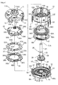
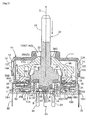
- a combined switch as shown in Figs. 1 through 5 comprises a casing 10, a control rod 20 supported by the casing 10 to extend upward, a tilt detecting section A for electrically detecting a tilting operation of the control rod 20, a depression detecting section B for electrically detecting a depressing operation of the control rod 20 executed along a rod axis Y of the control rod 20, and a rotation detecting section C for electrically detecting a rotational operation of the control rod 20.
- Such a combined switch is mountable on mobile phones, PDAs, game equipment controllers, remote controllers of household electric appliances, and the like. With this combined switch, the vertical direction is not relevant in use.
- the upside in Fig. 3 will be referred to as the upper side while the downside in Fig. 3 will be referred to as the lower side.
- control rod 20 maintains a neutral position N when resting in a non-operational state
- the tilt detecting section A detects crosswise tilting operations with reference to the neutral position N.
- the depression detecting section B electrically detects a depressing operation executed along the rod axis Y
- the rotation detecting section C electrically detects an amount of rotational operation about the rod axis Y of the control rod 20 resting in the neutral position N.
- the tilt detecting section A detects tilting operations of the control rod 20 in the four directions.
- the tilt detecting section may detect tilting operations in less than four directions, or five or more directions such as eight directions.
- the casing 10 includes a top cover 11, an upper case 12 and a lower case 13, which are connected to each other.
- Each of the top cover 11, the upper case 12 and the lower case 13 is formed by molding an insulating resin material in dies.
- each of the upper case 12 and the lower case 13 is generally octagonal as viewed from the direction along the rod axis Y in the neutral position N.
- the top cover 11 has a through bore 11A formed in a central portion thereof.
- the control rod 20 vertically extends through the through bore 11A.
- the top cover 11 has a concave guide surface 11G formed in a bottom surface side thereof which is equidistant from a tilt center P of the control rod 20.
- the top cover 11 has four connecting pieces 14 integrally formed with outer peripheries thereof to project downward. Each connecting piece 14 is provided at a distal end thereof with a hole-type engageable connecting portion 14A.
- the through bore 11A of the top cover 11 has a crosswise guide groove 11AG extending along tilting directions as viewed from the top.
- the guide groove 11AG has inner surfaces formed as inclined surfaces tapered toward the tilt center P.
- the upper case 12 includes a cylindrical side wall portion 12A extending along the rod axis Y in the neutral position N, and an intermediate wall portion 12B perpendicular to the rod axis Y in the neutral position N. These two wall portions are formed integrally with each other. As shown in Fig. 4 , the intermediate wall portion 12B has an aperture 12H formed in the central portion thereof.
- the side wall portion 12A has eight engaging pieces 12T (one example of engaging portions) projecting from outer peripheries thereof and arranged equidistantly in the circumferential direction.
- the intermediate wall portion 12B has four center electrodes 31 arranged on an upper surface thereof at regular intervals on a circumference centering on the control rod 20 to serve as four detecting positions.
- a generally ring-shaped ring electrode 32 is provided to surround each center electrode 31.
- independent tilt detecting circuits (not shown) conductive with the four center electrodes 31 individually, and a common circuit (not shown) conductive with the four ring electrodes 32, both of which are formed by insert molding.
- a common circuit (not shown) conductive with the four ring electrodes 32, both of which are formed by insert molding.
- four tilt detecting leads 33 project downward that are conductive with the tilt detecting circuits, while a single common lead 34 projects downward that is conductive with the common circuit.
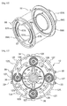
- the lower case 13 includes a cylindrical side wall portion 13A extending along the rod axis Y in the neutral position N, and a bottom wall portion 13B perpendicular to the rod axis Y in the neutral position N. These two wall portions are formed integrally with each other. On the central portion of the top surface of the bottom wall portion 13B are formed an annually projecting contact portion 13C for accommodating the depression detecting section B, and an annually projecting spring bearing 13D arranged concentrically with and outwardly of the contact portion.
- the side wall portion 13A of the lower case 13 includes four connecting pieces 16 formed integrally therewith to project upward.
- Each of the connecting pieces 15 has a hole-type engageable connecting portion 15A at a distal end thereof.
- the bottom wall portion 13B of the lower case 13 includes, in the central position thereof surrounded by the contact portion 13C, a center electrode 41 made of a conductor, and a ring electrode 42 made of a conductor and formed in a position surrounding the center electrode 41.
- a depression detecting circuit (not shown) conductive with the center electrode 41
- a ring circuit (not shown) conductive with the ring electrode 42, both of which are formed by insert molding.
- the bottom wall portion 13B further includes a depression detecting lead 43 conductive with the depression detecting circuit and projecting downward, and a ring lead 44 conductive with the ring circuit and projecting downward.
- the bottom wall portion 13B of the lower case 3 includes, arranged circumferentially of the spring bearing 13D, a ring-shaped common electrode 51 made of a conductor, and a plurality of count electrodes 52 made of conductors.
- the count electrodes 52 are surrounded by numerous ridges and grooves 53 for providing a clicking feel.
- the common electrode 51 is conductive with a common lead 54 through a circuit formed inside the bottom wall portion 13B of the lower case 13 by insert molding, while the count electrodes 52 are conductive with a count lead 55 through a circuit formed by insert molding. As shown in Figs. 1 and 3 , the common lead 54 and the count lead 55 project downward from the bottom wall portion 13B of the lower case 13. A plurality of lead holders 13H are formed on lower portions of the outer surface of the lower case 13. The four tilt detecting leads 33 and the one common lead 34 are inserted into apertures formed in the lead holders 13H.
- the control rod 20 is made using a relatively rigid material such as a copper alloy. As shown in Fig. 4 , the control rod includes an upper end portion 21 projecting upward from the casing 10 and having a D-cut portion 21A in a position for receiving a knob or the like, and an intermediate portion 22 having a cylindrical shape. A large diameter portion 23 is formed under the intermediate portion 22. Under the large diameter portion 23 are provided a plurality of engaging pieces 24 forming a gear-shaped element for outputting torque. At a bottom end of the control rod is formed a contact portion 25 having a spherical outer surface (see Fig. 3 ).
- a spring bearing member 26 made of resin is rigidly fitted on an intermediate position between the contact portion 25 and the gear-shaped engaging pieces 24.
- the contact portion 25 has a bulging spherical shape centering on the tilt center P.
- the tilt detecting section A includes dome-shaped spring plate elements 35 made of conductors and provided in the four detecting positions on the intermediate wall portion 12B of the upper case 12, shock absorbing elements 36A in contact with upper surfaces of the four spring plate elements 35, and an operative member 38 for exerting a depressing force on the spring plate elements 35 through the shock absorbing elements 36A when the control rod 20 is tilted.
- the spring plate elements 35 are arranged to cover the center electrodes 31 and ring electrodes 32.
- the four shock absorbing elements 36A are formed integrally with a rubber ring 36 (one example of ring members).
- a spring ring 37 made of a disk-shaped spring material is tightly mounted on an upper surface of the rubber ring 36.
- Each of the spring plate elements 35 employs a disk-shaped material made of a conductor such as a copper alloy, iron alloy or the like, and has a dome shape bulging upward at the central portion thereof. When free from a depressing force, each spring plate member 35 is in contact with the ring electrode 32 at the peripheral portion thereof and out of contact with the center electrode 31 at the central portion thereof.
- the central portion of the spring plate element 35 When a depressing force exceeding a predetermined value is exerted on the central portion of one of the spring plate elements 35 from above, the central portion of the spring plate element 35 is elastically deformed to contact the corresponding center electrode 31 thereby allowing the center electrode 31 to be conductive with the corresponding spring electrode 32.
- the drawings show a construction in which the single spring plate element 35 is provided in each detecting position. Instead, a plurality of spring plate elements 35 may be layered in each detecting position.
- the rubber ring 36 is made of a soft insulating material such as silicon rubber or the like.
- the shock absorbing elements 36A are formed integrally with the rubber ring 36 to project upward and downward from both the top and bottom surfaces of the rubber ring 36 in four positions.
- the spring ring 37 has bore portions 37A for receiving the shock absorbing elements 36A. As shown in Fig. 4 , the rubber ring 36 and the spring ring 37 have receiving bores 36S and 37S, respectively. Fitting pieces 12S projecting from the intermediate wall portion 12B are fitted to the receiving bores 36S and 37 thereby to support the rubber ring 36 and the spring ring 37 in position.
- the operative member 38 is formed by molding an insulating resin material.
- the operative member 38 includes a bore portion 38A formed in the center thereof, a convex slide contact surface 38G formed in a central top surface thereof for slidably contacting the guide surface 11G formed in the bottom side of the top cover 11, and four depressing portions 38B provided at outer peripheries thereof to project downward.
- the bore portion 38A has a plurality of grooves T formed in inner peripheries thereof to be parallel to the rod axis Y of the control rod 20.
- the depression detecting section B includes a dome-shaped spring plate element 45 covering the center electrode 41 and ring electrode 42 of the lower case 13, a first contact element 46 provided above the spring plate element 45, and a second contact element 47 fitted and connected to the first contact element. Further, a return spring 48 of the compression coil type is provided between the spring bearing 13D and the spring bearing member 26 of the control rod 20.
- the spring plate element 45 employs a disk-shaped material made of a conductor such as a copper alloy, iron alloy or the like, and has a dome shape bulging upward at the central portion thereof.
- the spring plate member 45 is in contact with the ring electrode 42 at the peripheral portion thereof and out of contact with the center electrode 41 at the-central portion thereof.
- the lower, first contact element 46 is made of a relatively soft insulating resin material such as silicon rubber or the like, while the upper, second contact element 47 is made of a relatively rigid insulating resin material.
- the first contact element 46 and the second contact element 47 are fitted and connected to each other.
- the lower, first contact element 46 is guided by the inner wall surface of the contact portion 13C to be vertically displaceable. Since the upper, second contact element 47 has a concave surface coinciding with the shape of the contact portion 25 formed at the lower end of the control rod 20, the contact portion 25 can reliably transmit pressure to the spring plate element 45 through the first contact element 46 even when the control rod 20 is more or less tilted.
- An amount of projection of the rib-like contact portion 13C from the bottom wall portion 13B of the lower case 13 is determined so that the contact portion 13C contacts the spring bearing member 26 when the control rod 20 is depressed and after the depression detecting section B reaches a detecting state by the depressing force exerted from the control rod 20.
- the rotation detecting section C includes a rotor 56 rotatable by the plurality of engaging pieces 24 formed on the control rod 20, a contact 57 formed on the lower surface of the rotor 56, and a click spring 58 formed on the lower surface of the rotor 56 as shown in Figs. 7 , 9 and 10 .
- the rotor 56 is formed by molding an insulating resin material, and includes a cylindrical portion 56A formed at the central portion thereof, a flange portion 56B formed at the lower end of the cylindrical portion 56A, and engageable portions 56C formed at the upper end of the cylindrical portion 56A for receiving the engaging pieces 24.
- the engageable portions 56C are formed to allow the engaging pieces 24 to be tilted with tilting of the control rod 20.
- the cylindrical portion 56A of the rotor 56 has an outside diameter determined to be insertable in the aperture 12H formed in the upper case 12, and an inside diameter at the lower end thereof to be slightly larger than the outside diameter of the contact portion 13C of the lower case 13. Therefore, with the combined switch in an assembled state, the outer surface of the cylindrical portion 56A of the rotor 56 is in light contact with the inner surface of the aperture 12H formed in the upper case 12, and at the same time the inner surface of the cylindrical portion 56A at the lower end thereof is in light contact with the contact portion 13C of the lower case 13. As a result, when the rotor 56 is rotated, a stable rotation is secured as guided by the inner surface of the aperture 12H and the outer surface of the contact portion 13.
- a rib is formed on the lower surface of the flange portion 56B of the rotor 56 to project downward.
- a distance between the lower end of the rib and the upper surface of the flange portion 56B is set to a value slight smaller than a vertical dimension of the space defined in the lower case 13.
- the contact 57 is formed as a ring-shaped member made of a conductor such as a copper alloy or the like.
- the contact 57 has main slide contact portions 57A formed in inner peripheries thereof to be in constant contact with the common electrode 51, and auxiliary slide contact portions 57B formed in outer peripheries thereof for slidably contacting the count electrodes 52 in specific circumferential positions.
- the count electrodes 52 are conductive with the common electrode 51 while the auxiliary slide contact portions 57B formed in the outer peripheries of the contact 57 are in contact with the count electrodes 52.
- the count electrodes 52 are isolated from the common electrode 51 while the auxiliary slide contact portions 57B are separated from the count electrodes 52.
- the click spring 58 is formed as a ring-shaped member made of a metal material that is flexibly and elastically deformable, and is deformed to project downward in two circumferential positions thereby forming a pair of projections 58A.
- the projections 58A are engaged with and disengaged from the ridges and grooves 53 formed on the bottom wall portion 13B of the lower case 13 for providing a clicking feel, which produces a clicking feel for the operator.
- the tilt detecting section A is assembled to the upper case 12. After the top cover 11 is connected to the upper case 12 (or in parallel with assembling the tilt detecting section A to the upper case 12), the depression detecting section B and the rotation detecting section C are assembled to the lower case 13. Then, the lower case 13 is connected to the upper case 12. Assembly may be carried out in this order.
- the assembling order is not limited to the above example.
- the depression detecting section B and the rotation detecting section C may be assembled to the lower case 13 first, then the upper case 12 may be connected to the lower case 13.
- the tilt detecting section A may be assembled to the upper case 12, and then the top cover 11 may be connected to the upper case 12.
- the spring plate elements 35 are arranged in positions to cover the center electrodes 31 and ring electrodes 32 formed in the four positions of the upper case 12.
- the spring ring 37 is placed over the rubber ring 36, and then the fitting pieces 12S of the intermediate wall portion 12B are fitted to the receiving bores 36S and 37S of the rubber ring 36 and the spring ring 37.
- the operative member 38 is placed on the rubber ring 36 and the spring ring 37.
- the positioning pieces (not shown) formed on the lower surface of the top cover 11 are fitted to the recesses 38S formed in the operative member 38, thereby to connect the top cover 11.
- the top cover 11 In connecting the top cover 11, the top cover 11 is placed in tight contact with the upper case 12. At the same time, any of the engageable connecting portions 14A of the connecting pieces 14 formed in the top cover 11 is allowed to be elastically fitted to any of the plurality of engaging pieces 12T formed in the side wall portion 12A of the upper case 12, whereby the connecting process is completed.
- the spring plate element 45 is placed to cover the center electrode 41 and the ring electrode 42 of the lower case 13 first, and then the first contact element 46 and the second contact element 47 fitted and connected to each other are placed on the spring plate element 45.
- the return spring 48 is placed in the spring bearing 13D on which the control rod 20 and the rotor 56 are placed in the mentioned order, thereby connecting the lower case 13 to the upper case 12.
- the positioning process is executed by inserting the control rod 20 supported by the lower case 13 into the bore portion 38A of the operative member 38 supported by the upper case 12, and then inserting the cylindrical portion 56A of the rotor 56 into the aperture H of the upper case 12. Consequently, the lower case 13 and the upper case 12 are in tight contact with each other along the axis Y, thereby allowing any of the engageable connecting portions 15A of the connecting pieces 15 formed in the lower case 13 to be elastically fitted to any corresponding one of the plurality of engaging pieces 12T formed in the side wall portion 12A of the upper case 12 to complete the connecting process. As a result, the combine switch is completed.
- the four tilt detecting leads 33 and the single common lead 24 provided in the upper case 12 are inserted into the apertures of the lead holders 13H, thereby realizing proper postures of the tilt detecting leads 33 and the common lead 34.
- the return spring 48 urges the control rod 20 upward by an urging force, and thus the operative member 38 contacts the upper end of the large diameter portion 23 of the control rod 20, thereby maintaining a contact state where the slide contact surface 38G of the operative member 38 contacts the guide surface 11G of the top cover 11. Also, the control rod 20 is maintained in the neutral position N by the urging force directly exerted on the control rod 20 from the return spring 48 and the force exerted on the operative member 38 from the shock absorbing elements 36A of the rubber ring 36 (provided that no external force is exerted).
- the spring plate elements 35 provided in the four detecting positions of the tilt detecting section A are maintained in positions spaced from the center electrodes 31, while the spring plate element 45 of the depression detecting section B is maintained in a position spaced from the center electrode 41.
- the main slide contact portions 57A formed in the inner peripheries of the contact 57 provided in the rotor 56 contact the common circuit 51 of the rotation detecting section C, while the auxiliary slide contact portions 57B formed in the outer peripheries of the contact 57 are in contact with or out of contact with the count electrodes 52.
- the slide contact surface 38G of the operative member 38 supported by the control rod 20 moves along the guide surface 11G formed on the bottom surface side of the top cover 11, whereby the control rod 20 is tilted centering on the tilt center P. Then, in response to the tilting operation, the spring plate element 35 corresponding to the tilting direction is elastically deformed to produce a clicking feel, which allows the operator to recognize that the state in which the tilting operation has reached a detectable state.
- the spring plate element 45 When the control rod 20 is depressed, the spring plate element 45 is elastically deformed to produce a clicking feel, which allows the operator to recognize that the depressing operation has reached a detectable state. Also, when the control rod 20 is depressed, the spring bearing member 26 of the control rod 20 contacts the rib-like contact portion 13C immediately after the center electrode 41 placed in the conductive state with the ring electrode 42 by the elastically deformed spring plate element 45. Further, since the first contact element 46 is flexibly and elastically deformed, it is possible to avoid a disadvantage of damaging the center electrode 41, the ring electrode 42, or the spring plate element 45 by an excessive operational force even when the control rod 20 is depressed by a strong force.
- control rod 20 is maintained in the neutral position N when the control rod 20 is depressed
- the spring bearing member 26 formed at the lower end of the control rod 20 contacts the contact portion 13C at the part thereof projecting most downward with the tilting operation, thereby exerting a force to return the control rod 20 to the neutral position N.
- the depressing operation is realized with the control rod 20 being moved close to the neutral position N.
- the count electrodes 52 and the common electrode 51 are brought to be conductive with each other when the auxiliary slide contact portions 57A provided at the outer peripheries of the contact 57 contact the count electrodes 52, while the count electrodes 52 and the common electrode 51 are brought to be insulated from each other when the auxiliary slide contact portions 57A are moved away from the count electrodes 52. Therefore, applying voltage to either the common electrode 51 or the count electrode 52 makes the voltage of a count lead 55 vary in a reverse direction with the rotation of the control rod 20.
- the projections 58A of the click spring 58 are repeatedly engaged with and disengaged from the ridges and grooves, and thus the clicking feel based on this engagement and disengagement allows the operator to recognize the rotating operation of the control rod 20.
- the four center electrodes 31 and the ring electrodes 32 constituting the tilt detecting section A in the intermediate wall portion 12B integrally formed with the upper case 12, place the spring plate elements 35 in the positions to cover these electrodes, lay the spring ring 37 on the rubber ring 36, place the operative member 38 on this unit, and then connect the top cover 11 thereto. Allowing an assembly in the mentioned order makes it possible to assemble the tilt detecting section A without considering an order of assembling the depression detecting section B and the rotation detecting section C.
- center electrode 41 and the ring electrode 42 of the depression detecting section B on the lower wall portion 13B integrally formed with the lower case 13, place the spring plate element 45 in the position to cover these electrodes, further provide the first contact element 46, the second contact element 47 and the compression coil spring 48, place the rotor 56 of the rotation detecting section C, and then connect the upper case 12 thereto. Allowing an assembly in the mentioned order makes it possible to assemble the depression detecting section B and the rotation detecting section C without considering an order of assembling the tilt detecting section A.
- the tilt detecting section A is arranged on the upper surface of the intermediate wall portion 12 integrally formed with the upper case 12, and the depression detecting section B and rotation detecting section C are arranged on the upper surface of the bottom wall portion 13B of the lower case 13.
- the upper case 12 includes the four tilt detecting leads 33 and the common lead 34 conductive with the tilt detecting section A, it is possible to confirm the conductive state of the tilt detecting section A during the assembling process, thereby allowing the operator to determine during the assembling process whether or not the tilt detecting section A is properly operable.
- the lower case 13 includes the depression detecting lead 43 and the ring lead 44 conductive with the depression detecting section B as well as the common lead 54 and the count lead 55 conductive with the rotation detecting section C, thereby allowing the operator to determine during the assembling process whether or not the depression detecting section B and the rotation detecting section C are properly operable.
- the operative member 38 for detecting the tilting movement of the control rod 20 is supported to be freely rotatable and slidable in the direction of the rod axis Y of the control rod 20, and the depression detecting section B for detecting the depression of the control rod 20 is provided in the bottom wall portion 13B of the lower case 13 to which the depressing force is transmitted directly from the control rod 20.
- the rotor 56 for detecting the rotation of the control rod 20 is rotated by the rotational force of the control rod 20, while allowing the tilting movement of the control rod 20.
- the rotational force is transmitted only to the rotor 56 without being transmitted to the operative member 38 or the depression detecting section B to rotate the rotor and vary the contact position of the contact 57, thereby allowing the rotation detecting section C to detect the rotational operation properly.
- the return spring 48 is disposed in the position surrounding the depression detecting section B.
- a biased load is applied to the return spring 48 to cause an urging force to act in the direction to return the control rod 20 to the neutral position N.
- the control rod 20 is guided by the bore portion 38A of the operative member 28 to be displaced along the rod axis Y.
- the spring bearing member 26 provided in the lower end of the control rod 20 contacts the contact portion 13C in the position closest to the contact portion, thereby to allow a restoring force to act on the control rod 20 in proportion to the depressing operational force.
- the control rod 20 when the control rod 20 is depressed while being tilted, the control rod 20 is returned to the neutral position N by the urging force of the return spring 48 and the force exerted from the contact portion 13C.
- the depressing force is exerted on the central position of the spring plate element 35 of the depression detecting section B to realize an operation for proper detection.
- the operator can recognize such exertion of the return force as a feel, which allows the operator of the switch to be aware of returning the control rod 20 to the neutral position N.
- the operative member 38 when the control rod 20 is tilted, the operative member 38 is tilted in unison with the control rod 20, a pressure from the depressing portions 38B is exerted on the spring plate elements 35 through the shock absorbing elements 36A to elastically deform the spring plate elements 35, as a result of which the center electrodes 31 become conductive with the ring electrodes 32.
- a great force is applied to the control rod 20 in the tilting direction, a corresponding shock absorbing element 36A is deformed to act on the associated spring plate element 35 over a large area, thereby avoiding a disadvantage that the spring plate element 35 is damaged by an excessive tilting force.
- the shock absorbing elements 36A project from the upper and lower surfaces of the rubber ring 36.
- the rubber ring 36 is in tight contact with the spring ring 37.
- the shock absorbing elements 36A formed on the rubber ring 36 are inserted into the bore portions 37A formed in the spring ring 37. Therefore, the shock absorbing elements 36A are in a fixed posture. Further, since urging forces exerted from the four shock absorbing elements 36A act on the four depressing portions 38B of the operative member 38, the control rod 20 is maintained in the neutral position N by the force exerted from the operative member 38 to the control rod 20.
- the receiving bores 36S and 37S formed in the rubber ring 36 and spring ring 37 are engaged with the fitting pieces 12S projecting from the intermediate wall portion 12B, whereby the positional relationship between the rubber ring 36, spring ring 37 and upper case 12 is properly maintained to allow the shock absorbing elements 36A formed on the rubber ring 36 to be properly positioned relative to the center electrodes 31 and ring electrodes 32.
- the operative member 38 is fitted on the control rod 20, thereby allowing relative movement along the rod axis Y between the control rod 20 and operative member 38 and relative rotation about the rod axis Y between the control rod 20 and operative member 38. Therefore, a depressing operation of the control rod 20 is detected by the depression detecting section B and a rotational operation of the control rod 20 is detected by the rotation detecting section C without influencing the tilt detecting section A.
- the present invention may be modified as indicated below apart from the embodiment described above.
Landscapes
- Switches With Compound Operations (AREA)
Applications Claiming Priority (5)
| Application Number | Priority Date | Filing Date | Title |
|---|---|---|---|
| JP2006043943A JP4511479B2 (ja) | 2006-02-21 | 2006-02-21 | 複合操作スイッチ |
| JP2006043946A JP4511481B2 (ja) | 2006-02-21 | 2006-02-21 | スイッチ |
| JP2006043944A JP4511480B2 (ja) | 2006-02-21 | 2006-02-21 | 複合操作スイッチ |
| JP2006043945A JP4439478B2 (ja) | 2006-02-21 | 2006-02-21 | 複合操作スイッチ |
| EP07708130.5A EP1988559B1 (fr) | 2006-02-21 | 2007-02-07 | Commutateur |
Related Parent Applications (2)
| Application Number | Title | Priority Date | Filing Date |
|---|---|---|---|
| EP07708130.5A Division EP1988559B1 (fr) | 2006-02-21 | 2007-02-07 | Commutateur |
| EP07708130.5A Division-Into EP1988559B1 (fr) | 2006-02-21 | 2007-02-07 | Commutateur |
Publications (3)
| Publication Number | Publication Date |
|---|---|
| EP2755220A2 true EP2755220A2 (fr) | 2014-07-16 |
| EP2755220A3 EP2755220A3 (fr) | 2014-08-27 |
| EP2755220B1 EP2755220B1 (fr) | 2017-11-22 |
Family
ID=38437234
Family Applications (4)
| Application Number | Title | Priority Date | Filing Date |
|---|---|---|---|
| EP14164435.1A Active EP2755221B1 (fr) | 2006-02-21 | 2007-02-07 | Commutateur |
| EP14164421.1A Active EP2755219B1 (fr) | 2006-02-21 | 2007-02-07 | Commutateur |
| EP07708130.5A Active EP1988559B1 (fr) | 2006-02-21 | 2007-02-07 | Commutateur |
| EP14164427.8A Active EP2755220B1 (fr) | 2006-02-21 | 2007-02-07 | Commutateur |
Family Applications Before (3)
| Application Number | Title | Priority Date | Filing Date |
|---|---|---|---|
| EP14164435.1A Active EP2755221B1 (fr) | 2006-02-21 | 2007-02-07 | Commutateur |
| EP14164421.1A Active EP2755219B1 (fr) | 2006-02-21 | 2007-02-07 | Commutateur |
| EP07708130.5A Active EP1988559B1 (fr) | 2006-02-21 | 2007-02-07 | Commutateur |
Country Status (6)
| Country | Link |
|---|---|
| US (2) | US8283583B2 (fr) |
| EP (4) | EP2755221B1 (fr) |
| KR (4) | KR101361741B1 (fr) |
| CA (1) | CA2642326C (fr) |
| TW (1) | TWI383417B (fr) |
| WO (1) | WO2007097194A1 (fr) |
Families Citing this family (36)
| Publication number | Priority date | Publication date | Assignee | Title |
|---|---|---|---|---|
| US7469381B2 (en) | 2007-01-07 | 2008-12-23 | Apple Inc. | List scrolling and document translation, scaling, and rotation on a touch-screen display |
| JP4551915B2 (ja) | 2007-07-03 | 2010-09-29 | ホシデン株式会社 | 複合操作型入力装置 |
| JP4868291B2 (ja) * | 2007-10-10 | 2012-02-01 | 株式会社デンソー | 車両用入力操作装置 |
| JP2009158389A (ja) * | 2007-12-27 | 2009-07-16 | Niles Co Ltd | スイッチ装置 |
| JP4553945B2 (ja) * | 2008-01-21 | 2010-09-29 | ホシデン株式会社 | 多方向スイッチ |
| KR101093943B1 (ko) * | 2009-06-23 | 2011-12-13 | 대성전기공업 주식회사 | 복합 스위치 유니트 및 이를 구비하는 복합 스위치 모듈 |
| WO2011146022A1 (fr) * | 2010-05-18 | 2011-11-24 | Pipistrel Podjetje Za Alternativno Letalstvo D.O.O. | Nouvelle interface utilisateur pour la commande d'un système de compensation d'aéronef |
| FR2965367B1 (fr) * | 2010-09-29 | 2012-08-31 | Delphi Tech Inc | Systeme de commandes a molette deplacable |
| WO2014092433A1 (fr) * | 2012-12-12 | 2014-06-19 | 대성전기공업 주식회사 | Unité d'interrupteur multifonction pour véhicules |
| US10691230B2 (en) | 2012-12-29 | 2020-06-23 | Apple Inc. | Crown input for a wearable electronic device |
| US10275117B2 (en) | 2012-12-29 | 2019-04-30 | Apple Inc. | User interface object manipulations in a user interface |
| US10001817B2 (en) | 2013-09-03 | 2018-06-19 | Apple Inc. | User interface for manipulating user interface objects with magnetic properties |
| US10503388B2 (en) * | 2013-09-03 | 2019-12-10 | Apple Inc. | Crown input for a wearable electronic device |
| US10545657B2 (en) | 2013-09-03 | 2020-01-28 | Apple Inc. | User interface for manipulating user interface objects |
| EP3047359B1 (fr) | 2013-09-03 | 2020-01-01 | Apple Inc. | Interface utilisateur pour manipuler des objets d'une interface utilisateur |
| US11068128B2 (en) | 2013-09-03 | 2021-07-20 | Apple Inc. | User interface object manipulations in a user interface |
| CN103618387A (zh) * | 2013-12-10 | 2014-03-05 | 国家电网公司 | 一种感知高压开关设备分合位置的智能装置和方法 |
| EP3161603B1 (fr) | 2014-06-27 | 2019-10-16 | Apple Inc. | Manipulation d'une application de calendrier dans un appareil avec écran tactile |
| US20160062571A1 (en) | 2014-09-02 | 2016-03-03 | Apple Inc. | Reduced size user interface |
| WO2016036414A1 (fr) | 2014-09-02 | 2016-03-10 | Apple Inc. | Fonctionnalité de boutons |
| TWI676127B (zh) | 2014-09-02 | 2019-11-01 | 美商蘋果公司 | 關於電子郵件使用者介面之方法、系統、電子器件及電腦可讀儲存媒體 |
| CN113824998B (zh) | 2014-09-02 | 2024-07-12 | 苹果公司 | 用于音乐用户界面的方法和设备 |
| US10365807B2 (en) | 2015-03-02 | 2019-07-30 | Apple Inc. | Control of system zoom magnification using a rotatable input mechanism |
| US10073489B2 (en) * | 2015-09-21 | 2018-09-11 | Deere & Company | Rolling return to neutral depressable control |
| CN106934450A (zh) * | 2017-03-30 | 2017-07-07 | 上海发那科机器人有限公司 | 一种板材检测装置 |
| CN108455457B (zh) * | 2017-09-05 | 2023-07-25 | 沈阳安洋自控设备有限公司 | 一种操作手柄 |
| FR3071076B1 (fr) * | 2017-09-13 | 2022-07-08 | Zodiac Aero Electric | Dispositif de commande pour interface homme-machine a elements electro-actifs |
| CN108242350A (zh) * | 2018-02-06 | 2018-07-03 | 温州长江汽车电子有限公司 | 多媒体遥控器 |
| CN111919275B (zh) * | 2018-04-11 | 2022-08-09 | 阿尔卑斯阿尔派株式会社 | 多方向输入装置 |
| US11435830B2 (en) | 2018-09-11 | 2022-09-06 | Apple Inc. | Content-based tactile outputs |
| US10712824B2 (en) | 2018-09-11 | 2020-07-14 | Apple Inc. | Content-based tactile outputs |
| JP7021040B2 (ja) * | 2018-09-25 | 2022-02-16 | ホシデン株式会社 | 多方向入力装置 |
| CN111668056A (zh) * | 2020-06-29 | 2020-09-15 | 深圳市致尚科技股份有限公司 | 多方向输入装置、手柄及游戏机 |
| CN112490053B (zh) * | 2020-11-19 | 2024-07-02 | 深圳市致尚科技股份有限公司 | 多方向输入装置和游戏机 |
| CN113745026B (zh) * | 2021-08-30 | 2024-05-28 | 北京歌尔泰克科技有限公司 | 多功能按键、电子设备及控制方法 |
| CN115576385A (zh) * | 2022-09-09 | 2023-01-06 | 泰兴市云叶农业科技有限公司 | 一种五自由度的手动操纵杆 |
Citations (1)
| Publication number | Priority date | Publication date | Assignee | Title |
|---|---|---|---|---|
| JP2005302642A (ja) | 2004-04-15 | 2005-10-27 | Alps Electric Co Ltd | 多方向入力装置 |
Family Cites Families (19)
| Publication number | Priority date | Publication date | Assignee | Title |
|---|---|---|---|---|
| US4874911A (en) * | 1988-03-28 | 1989-10-17 | Eaton Corporation | Electrical reversing switch |
| JP2916867B2 (ja) * | 1994-03-07 | 1999-07-05 | アルプス電気株式会社 | 多方向入力スイッチ |
| JP3694392B2 (ja) * | 1997-08-22 | 2005-09-14 | アルプス電気株式会社 | 複合操作型電気部品 |
| JP3816664B2 (ja) * | 1998-04-28 | 2006-08-30 | アルプス電気株式会社 | 多方向スイッチおよびこの多方向スイッチを用いた電子機器 |
| JP3856567B2 (ja) * | 1998-05-25 | 2006-12-13 | アルプス電気株式会社 | 複合操作型電気部品 |
| JP4019515B2 (ja) * | 1998-08-21 | 2007-12-12 | 松下電器産業株式会社 | 押圧・回動操作型電子部品およびこれを用いた通信端末機器 |
| JP2000123690A (ja) * | 1998-10-19 | 2000-04-28 | Smk Corp | 複合スイッチ |
| JP3737901B2 (ja) * | 1999-02-23 | 2006-01-25 | アルプス電気株式会社 | 多方向入力装置 |
| JP3896734B2 (ja) * | 1999-10-04 | 2007-03-22 | 松下電器産業株式会社 | 多方向操作スイッチおよびこれを用いた電子機器 |
| JP4414037B2 (ja) | 1999-12-28 | 2010-02-10 | 株式会社日立国際電気 | スイッチ装置 |
| JP3710668B2 (ja) * | 2000-02-14 | 2005-10-26 | ホシデン株式会社 | 多接点入力装置 |
| JP2001325860A (ja) * | 2000-05-16 | 2001-11-22 | Alps Electric Co Ltd | 複合操作型スイッチ装置 |
| JP4100879B2 (ja) * | 2001-03-12 | 2008-06-11 | アルプス電気株式会社 | 多方向入力装置 |
| JP2002280756A (ja) * | 2001-03-15 | 2002-09-27 | Toyobo Co Ltd | ケーシング構造 |
| JP2002343192A (ja) * | 2001-05-14 | 2002-11-29 | Alps Electric Co Ltd | 複合操作型入力装置 |
| JP3864812B2 (ja) * | 2002-03-07 | 2007-01-10 | 松下電器産業株式会社 | 複合操作型電子部品 |
| JP4057862B2 (ja) * | 2002-08-27 | 2008-03-05 | アルプス電気株式会社 | 複合操作型入力装置 |
| JP4055523B2 (ja) * | 2002-09-12 | 2008-03-05 | 松下電器産業株式会社 | 四方向操作スイッチ |
| JP2005166333A (ja) * | 2003-12-01 | 2005-06-23 | Alps Electric Co Ltd | 多方向入力装置 |
-
2007
- 2007-02-07 KR KR1020087022120A patent/KR101361741B1/ko active IP Right Grant
- 2007-02-07 KR KR1020137025233A patent/KR101425500B1/ko active IP Right Grant
- 2007-02-07 EP EP14164435.1A patent/EP2755221B1/fr active Active
- 2007-02-07 CA CA2642326A patent/CA2642326C/fr not_active Expired - Fee Related
- 2007-02-07 US US12/279,260 patent/US8283583B2/en not_active Expired - Fee Related
- 2007-02-07 EP EP14164421.1A patent/EP2755219B1/fr active Active
- 2007-02-07 EP EP07708130.5A patent/EP1988559B1/fr active Active
- 2007-02-07 KR KR1020137025234A patent/KR101425499B1/ko active IP Right Grant
- 2007-02-07 KR KR1020137025235A patent/KR101489721B1/ko active IP Right Grant
- 2007-02-07 WO PCT/JP2007/052086 patent/WO2007097194A1/fr active Application Filing
- 2007-02-07 EP EP14164427.8A patent/EP2755220B1/fr active Active
- 2007-02-12 TW TW096105114A patent/TWI383417B/zh active
-
2012
- 2012-07-31 US US13/563,183 patent/US8541701B2/en active Active
Patent Citations (1)
| Publication number | Priority date | Publication date | Assignee | Title |
|---|---|---|---|---|
| JP2005302642A (ja) | 2004-04-15 | 2005-10-27 | Alps Electric Co Ltd | 多方向入力装置 |
Also Published As
| Publication number | Publication date |
|---|---|
| EP2755221A2 (fr) | 2014-07-16 |
| KR101425500B1 (ko) | 2014-08-01 |
| EP2755220B1 (fr) | 2017-11-22 |
| US8541701B2 (en) | 2013-09-24 |
| KR101361741B1 (ko) | 2014-02-12 |
| TW200802466A (en) | 2008-01-01 |
| WO2007097194A1 (fr) | 2007-08-30 |
| EP2755221A3 (fr) | 2014-08-27 |
| KR101425499B1 (ko) | 2014-08-01 |
| EP2755219A2 (fr) | 2014-07-16 |
| TWI383417B (zh) | 2013-01-21 |
| EP1988559A4 (fr) | 2010-07-28 |
| EP2755219B1 (fr) | 2018-09-12 |
| CA2642326C (fr) | 2016-05-10 |
| EP2755219A3 (fr) | 2014-08-27 |
| KR101489721B1 (ko) | 2015-02-04 |
| CA2642326A1 (fr) | 2007-08-30 |
| EP1988559B1 (fr) | 2014-05-21 |
| KR20130113537A (ko) | 2013-10-15 |
| EP2755220A3 (fr) | 2014-08-27 |
| US20120292166A1 (en) | 2012-11-22 |
| KR20080106241A (ko) | 2008-12-04 |
| EP1988559A1 (fr) | 2008-11-05 |
| KR20130113539A (ko) | 2013-10-15 |
| KR20130113538A (ko) | 2013-10-15 |
| EP2755221B1 (fr) | 2017-03-08 |
| US20090050465A1 (en) | 2009-02-26 |
| US8283583B2 (en) | 2012-10-09 |
Similar Documents
| Publication | Publication Date | Title |
|---|---|---|
| EP2755221B1 (fr) | Commutateur | |
| JP4553945B2 (ja) | 多方向スイッチ | |
| JP4511479B2 (ja) | 複合操作スイッチ | |
| US7294795B1 (en) | Slide switch | |
| KR100913518B1 (ko) | 회전형 펄스 스위치 | |
| EP3709331B1 (fr) | Dispositif d'entrée | |
| JP4511481B2 (ja) | スイッチ | |
| JP4439478B2 (ja) | 複合操作スイッチ | |
| JP4511480B2 (ja) | 複合操作スイッチ | |
| JP2007066637A (ja) | 複合操作型スイッチ | |
| JP2007103140A (ja) | 多方向入力装置 |
Legal Events
| Date | Code | Title | Description |
|---|---|---|---|
| PUAI | Public reference made under article 153(3) epc to a published international application that has entered the european phase |
Free format text: ORIGINAL CODE: 0009012 |
|
| 17P | Request for examination filed |
Effective date: 20140415 |
|
| AC | Divisional application: reference to earlier application |
Ref document number: 1988559 Country of ref document: EP Kind code of ref document: P |
|
| AK | Designated contracting states |
Kind code of ref document: A2 Designated state(s): DE FI FR GB |
|
| PUAL | Search report despatched |
Free format text: ORIGINAL CODE: 0009013 |
|
| AK | Designated contracting states |
Kind code of ref document: A3 Designated state(s): DE FI FR GB |
|
| RIC1 | Information provided on ipc code assigned before grant |
Ipc: H01H 25/06 20060101AFI20140718BHEP Ipc: G05G 9/047 20060101ALI20140718BHEP Ipc: H01H 25/04 20060101ALI20140718BHEP |
|
| 17Q | First examination report despatched |
Effective date: 20160909 |
|
| STAA | Information on the status of an ep patent application or granted ep patent |
Free format text: STATUS: EXAMINATION IS IN PROGRESS |
|
| GRAP | Despatch of communication of intention to grant a patent |
Free format text: ORIGINAL CODE: EPIDOSNIGR1 |
|
| STAA | Information on the status of an ep patent application or granted ep patent |
Free format text: STATUS: GRANT OF PATENT IS INTENDED |
|
| INTG | Intention to grant announced |
Effective date: 20170608 |
|
| RIN1 | Information on inventor provided before grant (corrected) |
Inventor name: ASADA, MAKOTO |
|
| GRAS | Grant fee paid |
Free format text: ORIGINAL CODE: EPIDOSNIGR3 |
|
| GRAA | (expected) grant |
Free format text: ORIGINAL CODE: 0009210 |
|
| STAA | Information on the status of an ep patent application or granted ep patent |
Free format text: STATUS: THE PATENT HAS BEEN GRANTED |
|
| AC | Divisional application: reference to earlier application |
Ref document number: 1988559 Country of ref document: EP Kind code of ref document: P |
|
| AK | Designated contracting states |
Kind code of ref document: B1 Designated state(s): DE FI FR GB |
|
| REG | Reference to a national code |
Ref country code: GB Ref legal event code: FG4D |
|
| REG | Reference to a national code |
Ref country code: DE Ref legal event code: R096 Ref document number: 602007053177 Country of ref document: DE |
|
| REG | Reference to a national code |
Ref country code: FR Ref legal event code: PLFP Year of fee payment: 12 |
|
| REG | Reference to a national code |
Ref country code: DE Ref legal event code: R097 Ref document number: 602007053177 Country of ref document: DE |
|
| PLBE | No opposition filed within time limit |
Free format text: ORIGINAL CODE: 0009261 |
|
| STAA | Information on the status of an ep patent application or granted ep patent |
Free format text: STATUS: NO OPPOSITION FILED WITHIN TIME LIMIT |
|
| 26N | No opposition filed |
Effective date: 20180823 |
|
| PGFP | Annual fee paid to national office [announced via postgrant information from national office to epo] |
Ref country code: FI Payment date: 20240219 Year of fee payment: 18 Ref country code: DE Payment date: 20240123 Year of fee payment: 18 Ref country code: GB Payment date: 20240222 Year of fee payment: 18 |
|
| PGFP | Annual fee paid to national office [announced via postgrant information from national office to epo] |
Ref country code: FR Payment date: 20240222 Year of fee payment: 18 |