EP2754960B1 - Fluidized bed furnace and waste disposal method using fluidized bed furnace - Google Patents
Fluidized bed furnace and waste disposal method using fluidized bed furnace Download PDFInfo
- Publication number
- EP2754960B1 EP2754960B1 EP12830586.9A EP12830586A EP2754960B1 EP 2754960 B1 EP2754960 B1 EP 2754960B1 EP 12830586 A EP12830586 A EP 12830586A EP 2754960 B1 EP2754960 B1 EP 2754960B1
- Authority
- EP
- European Patent Office
- Prior art keywords
- bed
- fluidized
- fixed
- wastes
- furnace
- Prior art date
- Legal status (The legal status is an assumption and is not a legal conclusion. Google has not performed a legal analysis and makes no representation as to the accuracy of the status listed.)
- Active
Links
- 239000002699 waste material Substances 0.000 title claims description 115
- 238000000034 method Methods 0.000 title claims description 7
- 238000001035 drying Methods 0.000 claims description 25
- 230000000284 resting effect Effects 0.000 claims description 9
- 230000000694 effects Effects 0.000 claims description 4
- 238000000197 pyrolysis Methods 0.000 description 35
- 239000007789 gas Substances 0.000 description 29
- 238000009792 diffusion process Methods 0.000 description 21
- 230000005587 bubbling Effects 0.000 description 17
- 238000006243 chemical reaction Methods 0.000 description 16
- XLYOFNOQVPJJNP-UHFFFAOYSA-N water Substances O XLYOFNOQVPJJNP-UHFFFAOYSA-N 0.000 description 8
- 238000002485 combustion reaction Methods 0.000 description 7
- 230000001105 regulatory effect Effects 0.000 description 7
- VYPSYNLAJGMNEJ-UHFFFAOYSA-N Silicium dioxide Chemical compound O=[Si]=O VYPSYNLAJGMNEJ-UHFFFAOYSA-N 0.000 description 6
- 238000002309 gasification Methods 0.000 description 5
- 238000005192 partition Methods 0.000 description 5
- 239000000567 combustion gas Substances 0.000 description 4
- 239000000463 material Substances 0.000 description 4
- 239000002245 particle Substances 0.000 description 4
- 239000004576 sand Substances 0.000 description 4
- 239000010801 sewage sludge Substances 0.000 description 4
- 238000005243 fluidization Methods 0.000 description 3
- 230000008602 contraction Effects 0.000 description 2
- 230000018044 dehydration Effects 0.000 description 2
- 238000006297 dehydration reaction Methods 0.000 description 2
- 239000002360 explosive Substances 0.000 description 2
- 239000000446 fuel Substances 0.000 description 2
- 239000011800 void material Substances 0.000 description 2
- XUIMIQQOPSSXEZ-UHFFFAOYSA-N Silicon Chemical compound [Si] XUIMIQQOPSSXEZ-UHFFFAOYSA-N 0.000 description 1
- 238000009825 accumulation Methods 0.000 description 1
- 230000015572 biosynthetic process Effects 0.000 description 1
- 238000007599 discharging Methods 0.000 description 1
- 239000000428 dust Substances 0.000 description 1
- 229910052751 metal Inorganic materials 0.000 description 1
- 239000002184 metal Substances 0.000 description 1
- 150000002739 metals Chemical class 0.000 description 1
- 239000004570 mortar (masonry) Substances 0.000 description 1
- 230000002093 peripheral effect Effects 0.000 description 1
- 239000011241 protective layer Substances 0.000 description 1
- 239000011819 refractory material Substances 0.000 description 1
- 229910052710 silicon Inorganic materials 0.000 description 1
- 239000010703 silicon Substances 0.000 description 1
- 239000000377 silicon dioxide Substances 0.000 description 1
- 239000010802 sludge Substances 0.000 description 1
- 238000011144 upstream manufacturing Methods 0.000 description 1
- 239000002023 wood Substances 0.000 description 1
Images


Classifications
-
- F—MECHANICAL ENGINEERING; LIGHTING; HEATING; WEAPONS; BLASTING
- F23—COMBUSTION APPARATUS; COMBUSTION PROCESSES
- F23G—CREMATION FURNACES; CONSUMING WASTE PRODUCTS BY COMBUSTION
- F23G5/00—Incineration of waste; Incinerator constructions; Details, accessories or control therefor
- F23G5/02—Incineration of waste; Incinerator constructions; Details, accessories or control therefor with pretreatment
- F23G5/04—Incineration of waste; Incinerator constructions; Details, accessories or control therefor with pretreatment drying
-
- B—PERFORMING OPERATIONS; TRANSPORTING
- B09—DISPOSAL OF SOLID WASTE; RECLAMATION OF CONTAMINATED SOIL
- B09B—DISPOSAL OF SOLID WASTE
- B09B3/00—Destroying solid waste or transforming solid waste into something useful or harmless
-
- B—PERFORMING OPERATIONS; TRANSPORTING
- B09—DISPOSAL OF SOLID WASTE; RECLAMATION OF CONTAMINATED SOIL
- B09B—DISPOSAL OF SOLID WASTE
- B09B3/00—Destroying solid waste or transforming solid waste into something useful or harmless
- B09B3/40—Destroying solid waste or transforming solid waste into something useful or harmless involving thermal treatment, e.g. evaporation
-
- F—MECHANICAL ENGINEERING; LIGHTING; HEATING; WEAPONS; BLASTING
- F23—COMBUSTION APPARATUS; COMBUSTION PROCESSES
- F23C—METHODS OR APPARATUS FOR COMBUSTION USING FLUID FUEL OR SOLID FUEL SUSPENDED IN A CARRIER GAS OR AIR
- F23C10/00—Fluidised bed combustion apparatus
- F23C10/005—Fluidised bed combustion apparatus comprising two or more beds
-
- F—MECHANICAL ENGINEERING; LIGHTING; HEATING; WEAPONS; BLASTING
- F23—COMBUSTION APPARATUS; COMBUSTION PROCESSES
- F23C—METHODS OR APPARATUS FOR COMBUSTION USING FLUID FUEL OR SOLID FUEL SUSPENDED IN A CARRIER GAS OR AIR
- F23C10/00—Fluidised bed combustion apparatus
- F23C10/02—Fluidised bed combustion apparatus with means specially adapted for achieving or promoting a circulating movement of particles within the bed or for a recirculation of particles entrained from the bed
- F23C10/12—Fluidised bed combustion apparatus with means specially adapted for achieving or promoting a circulating movement of particles within the bed or for a recirculation of particles entrained from the bed the particles being circulated exclusively within the combustion zone
- F23C10/14—Fluidised bed combustion apparatus with means specially adapted for achieving or promoting a circulating movement of particles within the bed or for a recirculation of particles entrained from the bed the particles being circulated exclusively within the combustion zone the circulating movement being promoted by inducing differing degrees of fluidisation in different parts of the bed
-
- F—MECHANICAL ENGINEERING; LIGHTING; HEATING; WEAPONS; BLASTING
- F23—COMBUSTION APPARATUS; COMBUSTION PROCESSES
- F23C—METHODS OR APPARATUS FOR COMBUSTION USING FLUID FUEL OR SOLID FUEL SUSPENDED IN A CARRIER GAS OR AIR
- F23C10/00—Fluidised bed combustion apparatus
- F23C10/18—Details; Accessories
- F23C10/20—Inlets for fluidisation air, e.g. grids; Bottoms
-
- F—MECHANICAL ENGINEERING; LIGHTING; HEATING; WEAPONS; BLASTING
- F23—COMBUSTION APPARATUS; COMBUSTION PROCESSES
- F23G—CREMATION FURNACES; CONSUMING WASTE PRODUCTS BY COMBUSTION
- F23G5/00—Incineration of waste; Incinerator constructions; Details, accessories or control therefor
- F23G5/02—Incineration of waste; Incinerator constructions; Details, accessories or control therefor with pretreatment
- F23G5/027—Incineration of waste; Incinerator constructions; Details, accessories or control therefor with pretreatment pyrolising or gasifying stage
-
- F—MECHANICAL ENGINEERING; LIGHTING; HEATING; WEAPONS; BLASTING
- F23—COMBUSTION APPARATUS; COMBUSTION PROCESSES
- F23G—CREMATION FURNACES; CONSUMING WASTE PRODUCTS BY COMBUSTION
- F23G5/00—Incineration of waste; Incinerator constructions; Details, accessories or control therefor
- F23G5/30—Incineration of waste; Incinerator constructions; Details, accessories or control therefor having a fluidised bed
-
- F—MECHANICAL ENGINEERING; LIGHTING; HEATING; WEAPONS; BLASTING
- F23—COMBUSTION APPARATUS; COMBUSTION PROCESSES
- F23G—CREMATION FURNACES; CONSUMING WASTE PRODUCTS BY COMBUSTION
- F23G2201/00—Pretreatment
- F23G2201/10—Drying by heat
-
- F—MECHANICAL ENGINEERING; LIGHTING; HEATING; WEAPONS; BLASTING
- F23—COMBUSTION APPARATUS; COMBUSTION PROCESSES
- F23G—CREMATION FURNACES; CONSUMING WASTE PRODUCTS BY COMBUSTION
- F23G2203/00—Furnace arrangements
- F23G2203/40—Stationary bed furnace
- F23G2203/401—Stationary bed furnace with support for a grate or perforated plate
-
- F—MECHANICAL ENGINEERING; LIGHTING; HEATING; WEAPONS; BLASTING
- F23—COMBUSTION APPARATUS; COMBUSTION PROCESSES
- F23G—CREMATION FURNACES; CONSUMING WASTE PRODUCTS BY COMBUSTION
- F23G2203/00—Furnace arrangements
- F23G2203/50—Fluidised bed furnace
- F23G2203/502—Fluidised bed furnace with recirculation of bed material inside combustion chamber
-
- F—MECHANICAL ENGINEERING; LIGHTING; HEATING; WEAPONS; BLASTING
- F23—COMBUSTION APPARATUS; COMBUSTION PROCESSES
- F23G—CREMATION FURNACES; CONSUMING WASTE PRODUCTS BY COMBUSTION
- F23G2203/00—Furnace arrangements
- F23G2203/50—Fluidised bed furnace
- F23G2203/503—Fluidised bed furnace with two or more fluidised beds
-
- F—MECHANICAL ENGINEERING; LIGHTING; HEATING; WEAPONS; BLASTING
- F23—COMBUSTION APPARATUS; COMBUSTION PROCESSES
- F23G—CREMATION FURNACES; CONSUMING WASTE PRODUCTS BY COMBUSTION
- F23G2207/00—Control
- F23G2207/30—Oxidant supply
Definitions
- the present invention relates to a fluidized bed furnace for treating wastes, and more particularly to a fluidized bed furnace which is capable of treating wastes continuously and stably even if the wastes vary in quality and quantity, by drying and pyrolyzing the wastes slowly. Further, the present invention relates to a method for treating wastes using such fluidized bed furnace.
- a fluidized bed furnace is used in the field of waste treatment as an apparatus for performing a thermal reaction with an object to be treated in a fluidized bed.
- the fluidized bed furnace is configured to dry, pyrolyze and combust wastes in a short period of time by utilizing large thermal capacity of a fluidized medium (sand or the like) and supplying wastes into the fluidized medium heated to a high temperature.
- the fluidized bed furnace is used for an incinerator and a gasification furnace.
- the fluidized bed furnace has characteristics that a heat-transfer coefficient from the fluidized medium to the object to be treated is high so that the object to be treated is instantaneously heated by the fluidized medium heated to a high temperature, and the reaction proceeds sufficiently within a short period of time, and that incineration residues are clean as they contain no unburned matter, and metals can be easily recovered from the residues.
- the conventional fluidized bed furnaces are designed to keep a good fluidizing state of the fluidized medium in the entire fluidized bed, thereby eliminating any regions suffering poor fluidization, for the purpose of causing a reaction through the effective use of the entire fluidized bed.
- JP 57-166 411 A it is known that a poorly fluidized area inevitably occurs depending on the shape of a furnace bed in a specific region such as an outer peripheral bottom region of the fluidized bed. Since incombustibles are liable to be deposited in such a poorly fluidized area, in some cases, the fluidized bed furnace cannot perform incineration treatment (or gasification treatment) continuously. Therefore, as disclosed in JP 1-203814 A , attempts have been made to prevent a fluidized medium from becoming stagnant by providing an inclined wall around the bottom of the furnace, inclined surface blow nozzles along an inclined bottom surface of the bottom of the furnace, and lateral blow nozzles on side walls confronting each other across drain channels in the bottom of the furnace.
- CH 440 527 which relates to a fluidized bed furnace for sewage sludge, wherein combustion of the material takes place outside of the fluidized bed, which serves mainly as a drying and processing zone.
- the sewage sludge after dehydration is carried out of a fluidized bed of the fluidized bed furnace by air, which is blown into the material to form the fluidized bed.
- the sewage sludge after dehydration is discharged from the fluidized bed in the form of dust and burns above the fluidized bed.
- the fluidized bed features concentric zones which are individually controlled by corresponding valves depending on the required capacity.
- the center zone is always active and receives the highest amount of fluidizing air and is thereby fluidized most violently.
- the sewage sludge is charged into the center zone.
- the present inventors have focused attention on the fact that incineration treatment of the wastes can be stably performed even if the supplied wastes vary in quality and quantity, by drying and pyrolyzing the wastes slowly, in order to overcome the following drawbacks:
- the wastes such as municipal wastes that are non-uniform in quality and quantity
- the heat-transfer coefficient is high to allow a reaction to proceed within a short period of time in the fluidized bed furnace, it is difficult to maintain optimum combustion conditions according to fluctuations in quality and quantity of the supplied wastes.
- the present inventors have conceived the formation of a bed, in a fluidized bed furnace, which has a function to allow a reaction such as drying and pyrolysis to proceed slowly with time, and have made the present invention.
- Another object of the present invention is to provide a method for treating wastes using the above fluidized bed furnace.
- the fluidized bed furnace comprises a cylindrical furnace body whose horizontal section is substantially rectangular or circular a base plate disposed at a bottom portion of the furnace body and having gas supply ports for supplying a fluidizing gas to fluidize a fluidized medium; and a fluidized bed formed on the base plate in the furnace body to take the wastes into the fluidized medium and pyrolyze the wastes wherein the fluidized bed has a fixed-bed where the fluidized medium is kept in a resting state, the fixed-bed being formed at a furnace wall side of the furnace body; and a fluidized-bed where the fluidized medium is fluidized, the fluidized bed being located away from the furnace wall of the furnace body and adjacent to the fixed-bed; and an upper surface of the fixed-bed is formed by an inclined surface formed by the fluidized medium which has been scattered from the fluidized-bed.
- wastes are taken into the fluidized-bed and dried and pyrolyzed in the fluidized-bed, and the fluidized medium scattered from the fluidized-bed due to a splashing action of the fluidized medium of the fluidized-bed is supplied onto the fixed-bed.
- the fluidized medium that is supplied onto the fixed-bed forms a certain slope and slides down, thus forming a so-called angle of repose.
- a part of wastes are sprinkled together with the fluidized medium onto the upper surface of the fixed-bed and slide down along the slope, i.e., performing a so-called tumbling action, and thus drying and pyrolysis of the wastes proceeds slowly.
- the wastes are moved together with the fluidized medium onto the fixed-bed by utilizing a splashing action of the fluidized medium in an upper portion of the fluidized-bed, thereby allowing a reaction such as drying and pyrolysis of the wastes to proceed slowly with time, and thus the wastes can be dried and pyrolyzed slowly in the entire furnace.
- the fixed-bed is formed without supplying the fluidizing gas or is formed by supplying the fluidizing gas within a range for allowing the fluidized medium to form a fixed-bed.
- part of the gas supply ports of the base plate are closed so as not to supply the fluidizing gas to a certain region above the base plate, and thus the fixed-bed can be formed in this region. Further, the gas supply ports are not closed, but are adjusted to reduce the diameters of the holes of the gas supply ports so as to supply a small flow rate of fluidizing gas into the furnace within the range to maintain a fixed-bed where the fluidized medium is not moved or fluidized, thereby forming the fixed-bed.
- a supply amount of the fluidizing gas ejected from the gas supply ports of the base plate is differentiated in areas of the fluidized bed to make a fluidizing velocity larger in at least one area of the areas than in another area so that a moving-bed where the fluidized medium descends is formed in the another area and a fluidized-bed where the fluidized medium ascends is formed in the at least one area, and the wastes are supplied into the moving-bed.
- the wastes supplied to the moving-bed are swallowed by the moving-bed and moved downwardly together with the fluidized medium.
- the wastes are dried and pyrolyzed by the heat of the fluidized medium, and water content in the wastes is evaporated and a combustible gas is generated from the combustible content in the wastes, thus becoming a brittle pyrolysis residue.
- the pyrolysis residue typically contains the incombustibles and the unburned matter which becomes brittle by the pyrolysis.
- the pyrolysis residue that is generated in the moving-bed moves with the fluidized medium and reaches the base plate, the pyrolysis residue is directed along the slanted base plate toward the bottom of the fluidized-bed.
- the pyrolysis residue reaches the fluidized-bed, the unburned matter is separated from the incombustibles by the fluidizing air, and the remaining incombustibles from which the unburned matter has been separated is directed together with part of the fluidized medium toward the incombustible discharge port.
- the temperature of the fluidized-bed increases proportionally from the lower part to the upper part.
- part of the wastes supplied into the fluidized bed furnace are supplied together with the fluidized medium onto the upper surface of the fixed-bed by the splashing action of the fluidized medium in the upper parts of the fluidized-bed and the moving-bed.
- Part of the wastes slide down along the inclined surface of the upper surface of the fixed-bed, i.e., a so-called tumbling action is performed, and thus drying and pyrolysis of the wastes proceeds slowly, and the wastes are swallowed into the moving-bed.
- a circulating flow for circulating the fluidized medium between the moving-bed and the fluidized-bed is formed in the at least one area and the another area.
- the fixed-bed is formed on one side of the moving-bed and the fluidized-bed or is formed on both sides of the moving-bed and the fluidized-bed.
- the upper surface of the fluidized bed has a reduced area due to contraction by the deflector. Therefore, explosive fracture of air bubbles on the surface of the fluidized bed occurs relatively actively also in the upper portion of the moving-bed, and the fluidized medium also flies together with part of the wastes onto the upper portion of the fixed-bed formed adjacent to the moving-bed, and drying and gasification of part of the wastes proceeds by the mild tumbling action.
- the fluidized medium that has flowed into the moving-bed accepts the supplied wastes again, and repeats the thermal reactions in the moving-bed and the fluidized-bed.
- the fluidized-bed is a bubbling fluidized-bed where the fluidized medium repeats an up-and -down motion, and the wastes are supplied into the bubbling fluidized-bed.
- the fluidized medium scattered from the bubbling fluidized-bed due to a splashing action of the fluidized medium of the bubbling fluidized-bed is supplied onto the fixed-bed.
- the fluidized medium that has been supplied onto the fixed-bed forms a certain slope and slides down, thus forming a so-called angle of repose.
- a part of wastes are sprinkled together with the fluidized medium onto the upper surface of the fixed-bed, and slide down along the slope, i.e., performing a so-called tumbling action, and thus drying and pyrolysis of the wastes proceeds slowly.
- the fixed-bed is formed so as to surround the bubbling fluidized-bed.
- the fixed-bed is formed so as to surround the bubbling fluidized-bed, the fixed-bed having a large area can be ensured. Therefore, part of wastes can be scattered over the upper surface of the fixed-bed having a large area by a splashing action of the fluidized medium of the bubbling fluidized-bed, and a relatively large amount of wastes that have been scattered on the upper surface of the fixed-bed having a large area can be dried and pyrolyzed over time.
- a treating method for treating wastes comprising: supplying the wastes to a fluidized bed furnace in which a fixed-bed where a fluidized medium is kept in a resting state is formed in a fluidized bed, the fixed-bed being located adjacent to a fluidized-bed; and repeating a tumbling action to cause the wastes to slide down together with the fluidized medium along a certain inclination formed by the fluidized medium at an upper portion of the fixed-bed and to supply the wastes onto the upper portion of the fixed-bed again by a splashing effect of the fluidized medium, thereby drying and pyrolyzing the wastes slowly.
- the wastes are sprinkled together with the fluidized medium onto the upper surface of the fixed-bed, and slide down along the slope, i.e., a so-called tumbling action is performed, and thus drying and pyrolysis of the wastes proceeds slowly.
- a fixed-bed having a fluidized medium kept in a resting state is formed adjacent to a fluidized-bed in a fluidized bed furnace, and wastes are supplied together with the fluidized medium onto the upper surface of the fixed-bed by utilizing a splashing action of the fluidized medium in an upper portion of the fluidized-bed, thereby allowing a reaction such as drying and pyrolysis of the wastes to proceed slowly with time, and thus the wastes can be dried and pyrolyzed slowly in the entire furnace. Therefore, the wastes can be treated continuously and stably even if the wastes vary in quality and quantity.
- FIGS. 1 through 6 A fluidized bed furnace according to embodiments of the present invention will be described below with reference to FIGS. 1 through 6 .
- identical or corresponding parts are denoted by identical reference numerals, and will not be described in duplication.
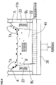
- FIG. 1 is a schematic vertical cross-sectional view of an overall structure of a fluidized bed furnace according to the present invention.
- the fluidized bed furnace 1 includes a furnace body 10 for treating wastes, a fluidized bed 20 for causing the wastes introduced therein to react thermally, and a base plate 30 for supporting the fluidized bed 20.
- the fluidized bed 20 is a bed which is formed by an accumulation of a fluidized medium composed typically of sand such as silica sand.
- the furnace body 10 comprises a furnace body having a substantially square tubular shape having a substantially rectangular horizontal cross section.
- the furnace body 10 having a substantially square tubular shape has a pair of side walls 11a, 11a facing each other and having portions that are concave inwardly, and a pair of side walls (11b in FIG. 3 ) facing each other and connected to the side walls 11a, 11a.
- Each of the concave portions of the furnace body 10 is formed by a slanted portion 11S1 inclined inwardly of the furnace body 10 from the lower part to the upper part and a slanted portion 11S2 disposed above the slanted portion 11S1 and inclined outwardly of the furnace body 10 from the lower part to the upper part.
- Each of the slanted portions 11S1 functions as a deflector for allowing an upward flow of the fluidized medium to turn easily toward the interior side of the furnace body 10.
- one of the side walls 11a has a supply port 15 for supplying an object to be treated (wastes) into the furnace.
- the other side wall 11a has an exhaust port 16 defined in an upper portion thereof for discharging gases that are generated when the wastes react thermally.
- a space above the fluidized bed 20 in the furnace body 10 serves as a freeboard 17.
- a combustion gas produced by combusting a combustible gas with secondary air supplied to the freeboard 17 is discharged from the exhaust port 16.
- a combustible gas is discharged from the exhaust port 16.
- the supply port 15 is provided in the side wall 11a at the location above the upper end of the slanted portion 11S2, and a chute for guiding the wastes supplied from the supply port 15 is formed to drop the wastes onto the central portion of the fluidized bed 20.
- the base plate 30, which is installed in the furnace body 10 has a chevron-shaped cross section which is highest at the center and is gradually lowered toward the opposite side edges. Incombustible discharge ports 18, 18 are formed between the opposite side edges of the base plate 30 and the side walls 11a, 11a.
- FIG. 2 is a perspective view showing a structure of the base plate 30 provided at the bottom of the furnace body 10.
- a width direction of the base plate 30 will be described as X direction
- a depth direction of the base plate 30 will be described as Y direction.
- the base plate 30 is highest at the center in the X direction, and has descending slopes that are progressively lower toward the opposite side edges.
- the base plate 30 is not slanted, but is flat in the Y direction.
- the base plate 30 has a number of gas diffusion nozzles 40 for ejecting fluidizing air as a fluidizing gas into the furnace.
- the air diffusion nozzles 40 constitute gas supply ports for supplying the fluidizing air as the fluidizing gas into the furnace to fluidize the fluidized medium.
- a bottom plate 33 is provided below the base plate 30 and spaced from the base plate 30.
- a space between the base plate 30 and the bottom plate 33 is divided into four spaces by three partition plates 34 that extend from the base plate 30 to the bottom plate 33. Since the space between the base plate 30 and the bottom plate 33 is divided by the three partition plates 34, two central air chambers 35, 35 and two side air chambers 36, 36 are formed below the base plate 30.
- the base plates for the air chambers 35, 35 are referred to as base plates 31, 31 and the base plates for the air chambers 36, 36 are referred to as base plates 32, 32.
- air pipes 51A, 51B, 52A, 52B are connected to the four air chambers 35, 35, 36, 36 respectively to supply the fluidizing air from outside of the furnace.
- the air pipes 51A, 51B, 52A, 52B have respective regulating valves V1-1, V1-2, V2-1, V2-2 for regulating the flow rate of air that flows in the air pipes 51A, 51B, 52A, 52B.
- the four air pipes 51A, 51B, 52A, 52B have upstream ends joined together into a single air pipe 55, and an air blower 56 for delivering fluidizing air under pressure is provided in the air pipe 55.
- the four air pipes 51A, 51B, 52A, 52B may alternatively have respective air blowers.
- air diffusion nozzles 40 which are positioned in predetermined ranges y1, y2 from the opposite ends of the base plate 30 in the Y direction are closed. Specifically, those air diffusion nozzles 40 which are positioned in the predetermined ranges y1, y2 from the opposite ends of the base plates 31, 31 and the base plates 32, 32 which constitute the base plate 30 are closed so as not to supply the fluidizing air as the fluidizing gas into the furnace.
- FIG. 3 is a plan view of the fluidized bed 20 having the base plate 30 with the air diffusion nozzles 30, constructed as shown in FIG. 2 .
- upper surfaces of fixed-beds 23 are illustrated, and the air diffusion nozzles 40 are omitted from illustration.
- the fluidizing air supply system that is arranged as shown in FIG. 1 , by adjusting the opening degrees of the regulating valves V1-1, V1-2 to regulate the flow rates of air flowing in the air pipes 51A, 51B, the fluidizing air is ejected from the air diffusion nozzles 40 disposed on the two central base plates 31, 31 so as to give a substantially small fluidizing velocity.
- FIG. 1 by adjusting the opening degrees of the regulating valves V1-1, V1-2 to regulate the flow rates of air flowing in the air pipes 51A, 51B, the fluidizing air is ejected from the air diffusion nozzles 40 disposed on the two central base plates 31, 31 so as to give a substantially small fluidizing velocity.
- weak fluidizing zones WF in which the fluidized medium is fluidized at a relatively low speed are formed on the two central base plates 31, 31. Further, by adjusting the opening degrees of the regulating valves V2-1, V2-2 to regulate the flow rates of air flowing in the air pipes 52A, 52B, the fluidizing air is ejected from the air diffusion nozzles 40 disposed on the two side base plates 32, 32 so as to give a substantially large fluidizing velocity. As a result, as shown in FIG. 3 , intense fluidizing zones SF in which the fluidized medium is fluidized actively are formed on the two side base plates 32, 32.
- the fluidized medium moves from the weak fluidizing zone WF to the intense fluidizing zone SF (from the moving-bed 21 to the fluidized-bed 22) in a lower portion of the entire region, whereas the fluidized medium moves from the intense fluidizing zone SF to the weak fluidizing zone WF (from the fluidized-bed 22 to the moving-bed 21) in an upper portion of the entire region, thus forming right and left circulating flows of the fluidized medium circulating between the weak fluidizing zone WF and the intense fluidizing zone SF (the moving-bed 1 and the fluidized-bed 22).
- the air diffusion nozzles 40 which are positioned in the predetermined ranges y1, y2 from both side walls 11b of the base plates 31, 31 and the base plates 32, 32 are closed and do not supply fluidizing air into the furnace. Therefore, the fixed-beds 23 where the fluidized medium is kept in a resting state are formed at both end portions of the base plates 31, 31 and the base plates 32, 32.
- the air diffusion nozzles 40 which are positioned in the predetermined ranges y1, y2 from both side walls 11b of the base plates 31, 31 and the base plates 32, 32 may not be closed, but may supply an amount of air within a range for allowing the fluidized medium to maintain fixed-beds into the furnace through adjustments to reduce the diameters of the holes of the nozzles, thereby forming the fixed-beds 23.
- the widths of the fixed-beds 23 having inclined surfaces (upper surfaces of the fixed-beds) at an angle of repose from the side walls 11b may be so large that incombustibles are liable to be accumulated on the upper surfaces of the fixed-beds 23 near the side walls 11b.
- the fixed-beds 23 adjacent respectively to the weak fluidizing zones WF and the intense fluidizing zones SF are schematically shown as being straight and having constant widths.
- the widths of the upper surfaces of the fixed-beds 23 adjacent to the weak fluidizing zones WF are slightly larger than the ranges of the fixed-beds 23 adjacent to the intense fluidizing zones SF.
- the widths on the base plate surfaces of the fixed-beds 23 adjacent to the weak fluidizing zones WF may be larger than the widths on the base plate surfaces of the fixed-beds 23 adjacent to the intense fluidizing zones SF.
- the distances of the fixed-beds 23 from the base plate ends in regions adjacent to the weak fluidizing zones WF where the wastes are dried and pyrolyzed are increased to widen the widths of the fixed-beds 23 in their regions adjacent to the weak fluidizing zones WF, so that the wastes are more slowly dried and pyrolyzed.
- the fixed-beds 23 are formed on both end portions of the base plates 31, 31 and the base plates 32, 32 by closing the air diffusion nozzles 40 in the predetermined ranges y1, y2 from the both side walls 11b of the base plate 31,31 and the base plate sections 32, 32.
- the ranges y1 and y2 of the fixed-beds 23 can be set to any value ranging from 300 to 600 mm, and thus the area of the fluidized bed that is formed in the furnace bottom of the fluidized bed furnace can be adjusted depending on the amount of wastes to be treated. Specifically, if the amount of wastes to be treated is reduced, the fixed beds 23 are widened to reduce the area of the fluidized bed, thus reducing the amount of fluidizing air depending on the amount of wastes.
- the fluidized bed furnace When the plant capacity is excessively large for the amount of wastes, the fluidized bed furnace has to be frequently shut down to meet the amount of accepted wastes, and hence extra electric power and fuel for increasing the temperature need to be consumed for starting up and shutting down the fluidized bed furnace.
- the area of the fluidized bed is reduced, a requisite minimum amount of fluidizing air is used to minimize the consumption of power so as to meet the amount of wastes, so that the fluidized bed furnace can continuously be operated.
- the deflectors (comprising the slanted portions 11S1 shown in FIG. 1 ) for allowing the fluidized medium to turn easily from upper portions of the fluidized-beds 22 into upper portions of the moving-beds 21 are provided.
- the fluidized medium is scattered from the fluidized-beds 22 also to upper portions of the fixed-beds 23 formed adjacent to the moving-beds 21. Since the upper surface of the fluidized bed 20 has its area reduced by constriction due to the deflectors, air bubbles on the surface of the fluidized bed 20 burst relatively actively also in the upper portions of the moving-beds 21. Consequently, the fluidized medium flies together with the object to be treated onto the upper portions of the fixed-beds 23 formed adjacent to the moving-beds 21, so that the object to be treated is slowly dried and gasified by a mild tumbling action.
- FIG. 4 is a cross-sectional view of the fluidized bed 20 taken along line IV - IV of FIG. 3 .
- the angle ( ⁇ ) of boundary lines BL between the fixed-beds 23 and the fluidized-bed 22 that are formed in the fluidized bed 20 is in the range of about a few degrees to 15°, though the angle increases as the amount of fluidizing air increases. Therefore, the widths of the upper surfaces of the fixed-beds adjacent to the weak fluidizing zones WF are slightly greater than the ranges of the fixed-beds adjacent to the intense fluidizing zones SF.
- the boundary lines BL are not fixed, but fluctuate due to fluctuation of the in-bed diffusion of the fluidizing air.
- the incombustibles Due to repeated tumbling actions, the incombustibles also slide down from the upper surfaces of the fixed-beds 23 into the fluidized-bed 22, and hence are not accumulated on the upper surfaces of the fixed-beds 23. While the object to be treated (wastes) including the incombustibles performs the tumbling action in the same manner as the movement of the fluidized medium as indicated by TA in FIG. 4 , the wastes are slowly dried and pyrolyzed.
- the object to be treated performs the same tumbling action as the fluidized medium. If the inclined surfaces are provided by walls that have a steep slant, then the object to be treated does not stay on the inclined surfaces, but slides down instantaneously into the fluidized-bed 22, so that the inclined surfaces do not exert any effect. Conversely, if the inclined surfaces are provided by walls that have a mild slant, then the object to be treated stays on the inclined surfaces, thus causing the incombustibles to start being accumulated thereon.
- the inclined surfaces are automatically formed depending on the properties of the fluidized medium by allowing the fluidized medium to form the fixed-beds.
- the fluidized medium it is necessary for the fluidized medium to form the inclined surfaces at the angle of repose in the regions (A in FIG. 4 ) above the points where the fixed-beds 23 intersect the upper surface of the fluidized-bed 22.
- the void ratio (the proportion of air bubbles) of the fluidized-bed 22 changes depending on the amount of fluidizing air supplied to the fluidized-bed 22, thus causing the position of the upper surface of the fluidized-bed 22 to vary vertically.
- the inclined surfaces are automatically formed at locations higher than the upper surface of the fluidized-bed 22 by allowing the fluidized medium to form the fixed-beds.
- the fluidized bed furnace of the present invention has the fluidized-bed 22 and the fixed-beds 23 that are simultaneously formed, and drying and pyrolysis zones of the object to be treated (wastes) that are formed in the upper portions of the fixed-beds 23, wherein the fluidized medium flying onto the fixed-beds 23 supplies heat required to dry and pyrolyze the object to be treated, thereby slowly drying and pyrolyzing the object to be treated, and the fluidized-bed 22 is used as a combustion zone of pyrolysis residue, thereby combusting combustibles reliably.
- the temperature of the fluidized bed is controlled by regulating the amount of pouring water supplied to the furnace bed besides the amount of fluidizing air so that the moving-bed 21 has a temperature of 450 to 600°C and the fluidized-bed 22 has a temperature of 550 to 650°C. If a furnace bed thermometer for detecting the temperature of the fluidized bed 20 is to be inserted from a side wall of the furnace body 10, then a temperature detecting element should be inserted to a depth ranging from 50 to 150 mm from the fixed-bed 23 into the fluidized bed, and should be installed 300 mm or more above the base plate and 100 mm or more below the upper surface of the sand bed at a stationary time.
- the fluidized bed furnace can be started up by fluidizing the fluidized medium and supplying the wastes.
- the fixed-bed 23 is formed by the fluidized medium between the furnace bed, which is fluidized, and the furnace wall, and the fixed-bed 23 acts as a protective layer for the temperature of the fluidized bed to prevent the temperature of the furnace bed from being lowered at the time of shutdown.
- the restart after the shutdown can easily be performed and the amount of an assistive fuel required for the restart can greatly be reduced.
- the fixed-beds 23 by the fluidized medium are formed on the base plate 30.
- walls which project inwardly from the side walls 11b of the furnace may be formed at a position above the base plate 30 and below the upper surface of the fluidized-bed, and the fluidized medium may be accumulated on the projecting walls by using a splashing action of the fluidized medium of the fluidized-bed, thereby forming fixed-beds.
- the space below the base plate 30 is divided into the four air chambers 35, 35, 36, 36 by the partition plates 34.
- the partition plates 34 may be omitted, and the space may be used as a single air chamber. In such a case, the number of air diffusion nozzles per unit area may be different in each region. Further, the air chambers 35, 36 may be further divided.
- the wastes as the object to be treated by the fluidized bed furnace 1 are typically expected to be materials which are non-uniform in quality and quantity and are liable to be combusted unstably, such as municipal wastes, sludge, wood debris, etc.
- the wastes will be described as municipal wastes.
- the wastes are generally composed of water content, combustible content, and ash content (including incombustibles). In a thermal reaction, the water content is evaporated, and the combustible content is partly volatilized as a combustible gas (pyrolysis gas) to become pyrolysis residue.
- an unburned matter (char) and incombustibles Materials that are left after water content is evaporated and a combustible gas is volatilized from the wastes, i.e., an unburned matter (char) and incombustibles, are the pyrolysis residue. It is preferable that the unburned matter (char) in the pyrolysis residue is separated from the incombustibles in the fluidized-bed 22, and part of the unburned matter (char) is combusted in the fluidized-bed 22 and delivered as a combustion gas and minute unburned matter (char) together with the fluidizing air into the freeboard 17.
- the wastes are supplied from the supply port 15 to the moving-beds 21.
- the opening degrees of the regulating valves V1-1, V1-2, V2-1, V2-2 are adjusted to regulate the flow rates of the fluidizing air supplied to the moving-beds 21 and the fluidized-beds 22.
- the mass flow rate of the fluidizing air supplied to the moving-bed 21 is adjusted to be smaller than the mass flow rate of the fluidizing air supplied to the fluidized-bed 22.
- the mass flow rate of the fluidizing air supplied to the moving-bed 21 is adjusted in the range of 0.5 to 1.5 Gmf
- the mass flow rate of the fluidizing air supplied to the fluidized-bed 22 is adjusted in the range of about 1.5 to 5 Gmf.
- the mass flow rate at the time of starting fluidization of the fluidized medium is 1 Gmf.
- a part of the wastes which have been supplied to the moving-bed 21 are supplied, together with the fluidized medium scattering from the fluidized bed by a splashing action of the fluidized medium of the fluidized bed, onto the fixed-bed 23.
- the wastes supplied onto the upper surface of the fixed-bed 23 slides down along the inclined surface together with the fluidized medium of the upper surface of the fixed-bed, i.e., a so-called tumbling action is performed, and thus drying and pyrolysis of the wastes proceeds slowly.
- the wastes which have not been splashed by the fluidized medium are swallowed into the moving-bed 21 and move downwardly together with the fluidized medium.
- the wastes are dried and pyrolyzed by the heat of the fluidized medium, and water content in the wastes is evaporated and a combustible gas is generated from the combustible content in the wastes, thus becoming a brittle pyrolysis residue.
- the pyrolysis residue typically contains the incombustibles and the unburned matter (char) which becomes brittle by the pyrolysis.
- the pyrolysis residue When the pyrolysis residue reaches the fluidized-bed 22, the pyrolysis residue contacts the fluidized medium which is fluidized intensely and the unburned matter (char) is separated from the incombustibles, and the remaining incombustibles from which the unburned matter (char) has been separated is directed together with part of the fluidized medium toward the incombustible discharge port 18.
- the incombustibles flow together with part of the fluidized medium into the incombustible discharge port 18, and are then discharged outside the fluidized bed furnace 1.
- the discharged incombustibles are collected in an unoxidized state and with no unburned matter (char) being attached in an incombustible separator (not shown).
- the fluidized medium from which the incombustibles have been separated by the incombustible separator (not shown) is returned into the furnace body 10 by a fluidized medium circulator (not shown).
- the unburned matter which has been separated from the incombustibles in the fluidized-bed 22 moves upwardly together with the fluidized medium which is fluidized by supplying the fluidizing air.
- the unburned matter is combusted by the supplied fluidizing air to heat the fluidized medium and to generate a combustion gas, thus becoming an unburned matter and ash particles that are fine enough to be carried by the gas.
- part of wastes which have not been pyrolyzed, and remain are also pyrolyzed.
- the temperature of the fluidized-bed 22 increases proportionally from the lower part to the upper part.
- part of the unburned matter is supplied together with the fluidized medium onto the upper surface of the fixed-bed 23 by the splashing action of the fluidized medium in the upper part of the fluidized-bed 22, and the remaining unburned matter is supplied onto the upper surface of the moving-bed and swallowed again into the moving-bed.
- the unburned matter supplied onto the upper surface of the fixed-bed 23 slides down along the inclined surface of the upper surface of the fixed-bed 23 together with part of the wastes, i.e., a so-called tumbling action is performed, and thus drying and pyrolysis of the unburned matter proceeds slowly. Since the deflector (comprising the slanted portion 11S1 shown in FIG.
- the fluidized medium is scattered from the fluidized-bed 22 also to the upper portion of the fixed-bed 23 formed adjacent to the moving-bed 21. Further, since the upper surface of the fluidized bed 20 has a reduced area due to contraction by the deflector, explosive fracture of air bubbles on the surface of the fluidized bed 20 occurs relatively actively also in the upper portion of the moving-bed 21.
- the fluidized medium also flies together with part of the wastes and the unburned matter onto the upper portion of the fixed-bed 23 formed adjacent to the moving-bed 21, and drying and gasification of part of the wastes and the unburned matter proceeds slowly over time by the mild tumbling action.
- the fluidized medium that has flowed into the moving-bed 21 accepts the supplied wastes again, and repeats the above thermal reactions in the moving-bed 21 and the fluidized-bed 22.
- the wastes such as municipal wastes are difficult to combust stably because they vary in terms of calorific values. If the wastes that are introduced into the fluidized bed furnace 1 per unit time are not stable in quality and quantity, then the amount of water vapor due to drying and the amounts of a combustible gas and a combustion gas that are produced due to the pyrolysis fluctuate, resulting in variations in the pressure in the fluidized bed furnace 1. Thus, the fluidized bed furnace 1 becomes difficult to operate stably. In order to suppress fluctuations in the amounts of the water vapor, the combustible gas, and the like that are produced, it is preferable to dry and pyrolyze the wastes in the fluidized bed 20 as slowly as possible.
- the fluidized-bed 22 and the fixed-bed 23 are concurrently formed and the drying and pyrolysis zone of the object to be treated (wastes) is formed in the upper part of the fixed-bed 23, and heat supply required for drying and pyrolysis is performed by the fluidized medium which flies onto the upper part of the fixed-bed 23.
- drying and pyrolysis of the object to be treated (wastes) is carried out slowly, and combustion of the combustibles can be carried out reliably in the fluidized-bed 22 serving as a combustion zone of the pyrolysis residue.
- FIGS. 5A, 5B, 5C, and 5D are schematic plan views showing fluidized bed furnaces according to various embodiments of the present invention.
- FIG. 5A shows a swirling-flow-type fluidized bed furnace having a rectangular fluidized bed 20 disposed in a cylindrical furnace body 10.
- a moving-bed 21 is formed centrally in the cylindrical furnace body 10
- fluidized-beds 22, 22 are formed on both sides of the moving-bed 21.
- Fixed-beds 23, 23 are formed on both sides of the moving-bed 21 and the fluidized-beds 22.
- Incombustible discharge ports 18 are formed outside of the fluidized-beds 22, 22.
- the furnace body of the fluidized bed furnace according to the present embodiment has a cylindrical shape, the furnace body is the simplest in structure and can easily be manufactured.
- As the furnace wall has a cylindrical shape, durability of a refractory material is improved.
- a thermal reaction occurs in the fluidized bed 20 in the same manner as with the fluidized bed furnace shown in FIG. 3 .
- FIG. 5B shows a swirling-flow-type fluidized bed furnace which has a fluidized bed 20 having a fixed-bed 23 formed on one side of a moving-bed 21 and fluidized-beds 22.
- the moving-bed 21 is formed centrally in a furnace body 10
- the fluidized-beds 22, 22 are formed on both sides of the moving-bed 21.
- the fixed-bed 23 is formed on one side of the moving-bed 21 and the fluidized-beds 22.
- incombustible discharge ports 18 are formed outside of the fluidized-beds 22, 22.
- a thermal reaction occurs in the moving-bed 21, the fluidized-beds 22, and the fixed-bed 23 in the same manner as with the fluidized bed furnace shown in FIG. 3 .
- FIGS. 5C and 5D show examples wherein a fixed-bed 23 or fixed-beds 23 are formed in a one-sided swirling-flow-type fluidized bed furnace.
- a single moving-bed 21 and a single fluidized-bed 22 are formed in a furnace body 10
- fixed-beds 23 are formed on both sides of the moving-bed 21 and the fluidized-bed 22.
- an incombustible discharge port 18 is formed outside of the fluidized-bed 22.
- a thermal reaction occurs in the moving-bed 21, the fluidized-bed 22, and the fixed-beds 23 in the same manner as with the fluidized bed furnace shown in FIG. 3 .
- a single moving-bed 21 and a single fluidized-bed 22 are formed in a furnace body 10, and a fixed-bed 23 is formed on one side of the moving-bed 21 and the fluidized-bed 22. Further, an incombustible discharge port 18 is formed outside of the fluidized-bed 22. A thermal reaction occurs in the moving-bed 21, the fluidized-bed 22, and the fixed-bed 23 in the same manner as with the fluidized bed furnace shown in FIG. 3 .
- FIGS. 6A and 6B show an example wherein a fixed-bed 23 is formed in a bubbling-type fluidized bed furnace.
- FIG. 6A is a schematic plan view
- FIG. 6B is a schematic vertical cross-sectional view.
- an incombustible discharge port 18 is disposed centrally in a cylindrical furnace body 10.
- a base plate 30 on the bottom of the furnace body 10 has a generally inverted conical shape (mortar shape) disposed around the incombustible discharge port 18.
- the base plate 30 has a number of air diffusion nozzles (not shown) for ejecting fluidizing air as a fluidizing gas into the furnace.
- the air diffusion nozzles are configured to eject uniform amounts of fluidizing air.
- the air diffusion nozzles which are positioned within a predetermined range y1 from a cylindrical furnace wall 11 are closed so as not to supply fluidizing air therefrom into the furnace.
- a fixed-bed 23 where the fluidized medium is kept in a resting state is formed in an annular region within the range y1 from the furnace wall 11.
- a fluidized bed 20 which comprises a bubbling fluidized-bed 24 having a circular cross section disposed around the incombustible discharge port 18 and a fixed-bed 23 having a substantially annular cross section disposed around the bubbling fluidized-bed 24 is formed.
- the air diffusion nozzles which are positioned within the predetermined range y1 from the furnace wall 11 may not be closed, but may be adjusted to reduce the diameters of the holes of the nozzles to supply a small amount of air into the furnace within the range to maintain a so-called fixed-bed where the fluidized medium is not moved or fluidized, thereby forming the fixed-bed 23.
- the angle ( ⁇ ) of boundary lines BL between the fixed-bed 23 and the bubbling fluidized-bed 24 that are formed in the fluidized bed 20 varies depending on the shape of the fluidized medium and the amount of fluidizing air.
- the angle ( ⁇ ) of boundary lines BL is in the range of about a few degrees to 15°, though it increases as the amount of fluidizing air increases.
- the boundary lines BL are not fixed, but fluctuate due to the fluctuation of the in-bed diffusion of the fluidizing air. Consequently, the incombustibles do not remain stagnant on the boundary lines BL, and hence do not start being accumulated at the boundary lines BL.
- the fluidized medium scattered from the bubbling fluidized-bed 24 due to a splashing action of the fluidized medium of the bubbling fluidized-bed 24 is supplied onto the fixed-bed 23.
- the fluidized medium that has been supplied onto the fixed-bed 23 forms a certain slope and slides down, thus forming a so-called angle of repose.
- the fluidized medium is sprinkled onto the upper surface of the fixed-bed 23 and slides down along the slope, i.e., performing a so-called tumbling action.
- the incombustibles Due to the repeated tumbling actions, the incombustibles also slide down from the upper surface of the fixed-bed 23 into the bubbling fluidized-bed 24, and hence are not accumulated on the upper surface of the fixed-bed 23. While the object to be treated (wastes) including the incombustibles performs the tumbling action in the same manner as the movement of the fluidized medium as indicated by TA in FIG. 6B , drying and pyrolysis of the wastes proceeds slowly.
- the slope (so-called angle of repose) formed in the upper portion of the fixed-bed varies depending on the particle diameter of the fluidized medium and the shape of the fluidized medium.
- part of the fluidized medium is replaced with ash composed mainly of silicon contained in the object to be treated, and the angle of repose also changes.
- the angle of repose is automatically adjusted depending on the properties (particle diameter, shape, etc.) of the fluidized medium, thus enabling the tumbling action to continue.
- the inclined surface needs to be formed by the fluidized medium at the angle of repose in the region (A in FIG. 6B ) above the point where the fixed-bed 23 intersects the upper surface of the fluidized-bed 24.
- the void ratio (the proportion of air bubbles) of the fluidized-bed 24 changes depending on the amount of fluidizing air supplied to the fluidized-bed 24, causing the position of the upper surface of the fluidized-bed 24 to vary vertically.
- the inclined surface is automatically formed at a position above the upper surface of the fluidized-bed 24 by allowing the fluidized medium to form the fixed-bed.
- FIG. 6C is a schematic plan view showing an example wherein a fixed-bed 23 is formed in a rectangular bubbling-type fluidized bed furnace.
- an incombustible discharge port 18 is formed centrally in a rectangular furnace body 10, and a fixed-bed 23 with a fluidized medium kept in a resting state is formed in a region within a range y1 from an inner wall of the furnace body 10.
- a bubbling fluidized-bed 24 having a substantially rectangular cross section is formed inwardly of the fixed-bed 23.
- a thermal reaction occurs in the fixed-bed 23 and the bubbling fluidized-bed 24 in the same manner as with the fluidized bed furnace shown in FIGS. 6A and 6B .
- the present invention is applicable to a fluidized bed furnace and a method for treating wastes using such fluidized bed furnace which are capable of treating wastes continuously and stably even if the wastes vary in quality and quantity, by drying and pyrolyzing the wastes slowly.
Applications Claiming Priority (2)
| Application Number | Priority Date | Filing Date | Title |
|---|---|---|---|
| JP2011195283 | 2011-09-07 | ||
| PCT/JP2012/071964 WO2013035615A1 (ja) | 2011-09-07 | 2012-08-30 | 流動床炉及び流動床炉を用いた廃棄物の処理方法 |
Publications (3)
| Publication Number | Publication Date |
|---|---|
| EP2754960A1 EP2754960A1 (en) | 2014-07-16 |
| EP2754960A4 EP2754960A4 (en) | 2015-05-06 |
| EP2754960B1 true EP2754960B1 (en) | 2019-03-06 |
Family
ID=47832062
Family Applications (1)
| Application Number | Title | Priority Date | Filing Date |
|---|---|---|---|
| EP12830586.9A Active EP2754960B1 (en) | 2011-09-07 | 2012-08-30 | Fluidized bed furnace and waste disposal method using fluidized bed furnace |
Country Status (4)
| Country | Link |
|---|---|
| EP (1) | EP2754960B1 (zh) |
| JP (1) | JP5898217B2 (zh) |
| CN (1) | CN103765103B (zh) |
| WO (1) | WO2013035615A1 (zh) |
Families Citing this family (3)
| Publication number | Priority date | Publication date | Assignee | Title |
|---|---|---|---|---|
| GB2503065B (en) | 2013-02-20 | 2014-11-05 | Recycling Technologies Ltd | Process and apparatus for treating waste comprising mixed plastic waste |
| JP6338430B2 (ja) * | 2014-04-16 | 2018-06-06 | 荏原環境プラント株式会社 | 旋回流型流動床炉 |
| CN104315519B (zh) * | 2014-10-08 | 2017-01-11 | 中国科学院广州能源研究所 | 一种高含氮可燃废弃物低污染自洁净燃烧方法及装置 |
Family Cites Families (14)
| Publication number | Priority date | Publication date | Assignee | Title |
|---|---|---|---|---|
| JP3153091B2 (ja) * | 1994-03-10 | 2001-04-03 | 株式会社荏原製作所 | 廃棄物の処理方法及びガス化及び熔融燃焼装置 |
| CH440527A (de) * | 1962-12-19 | 1967-07-31 | Haniel & Lueg Gmbh | Verfahren zur Verbrennung von Klärschlamm unter Verwendung eines Wirbelschichtofens |
| JPS57166411A (en) | 1981-04-04 | 1982-10-13 | Kawasaki Heavy Ind Ltd | Fluidized bed combustion equipment provided with load regulating function and optimum fluidizing function |
| JPS6117808A (ja) * | 1984-07-04 | 1986-01-25 | Babcock Hitachi Kk | 流動層ボイラ |
| JPS63108109A (ja) * | 1986-10-27 | 1988-05-13 | Ebara Corp | 熱回収装置の伝熱面 |
| JPH01203814A (ja) | 1988-02-10 | 1989-08-16 | Babcock Hitachi Kk | 流動層燃焼装置 |
| JPH0735883B1 (zh) * | 1988-08-31 | 1995-04-19 | ||
| JP3145463B2 (ja) * | 1992-02-12 | 2001-03-12 | バブコック日立株式会社 | 流動層燃焼炉の燃焼方法 |
| US5422080A (en) * | 1994-03-09 | 1995-06-06 | Tampella Power Corporation | Solids circulation enhancing air distribution grid |
| TW270970B (en) * | 1995-04-26 | 1996-02-21 | Ehara Seisakusho Kk | Fluidized bed combustion device |
| JP3877361B2 (ja) * | 1995-11-15 | 2007-02-07 | 株式会社荏原製作所 | 流動層反応装置 |
| US6139805A (en) * | 1995-11-15 | 2000-10-31 | Ebara Corporation | Fluidized-bed reactor |
| CN1711445A (zh) * | 2002-11-15 | 2005-12-21 | 株式会社荏原制作所 | 流化床气化炉 |
| RU2006114036A (ru) * | 2003-09-26 | 2006-08-27 | Ибара Корпорейшн (JP) | Система удаления негорючих материалов из печи с псевдоожиженным слоем |
-
2012
- 2012-08-30 EP EP12830586.9A patent/EP2754960B1/en active Active
- 2012-08-30 JP JP2013532556A patent/JP5898217B2/ja active Active
- 2012-08-30 WO PCT/JP2012/071964 patent/WO2013035615A1/ja active Application Filing
- 2012-08-30 CN CN201280042776.9A patent/CN103765103B/zh active Active
Non-Patent Citations (1)
| Title |
|---|
| None * |
Also Published As
| Publication number | Publication date |
|---|---|
| WO2013035615A1 (ja) | 2013-03-14 |
| JP5898217B2 (ja) | 2016-04-06 |
| CN103765103A (zh) | 2014-04-30 |
| JPWO2013035615A1 (ja) | 2015-03-23 |
| EP2754960A1 (en) | 2014-07-16 |
| EP2754960A4 (en) | 2015-05-06 |
| CN103765103B (zh) | 2016-01-06 |
Similar Documents
| Publication | Publication Date | Title |
|---|---|---|
| RU2159896C2 (ru) | Термическое реакционное устройство с псевдоожиженным слоем (варианты) | |
| US8317886B2 (en) | Apparatus and method for gasifying solid organic materials | |
| JP4548785B2 (ja) | 廃棄物ガス化溶融装置の溶融炉、並びに該溶融炉における制御方法及び装置 | |
| JP5744904B2 (ja) | 流動床炉及び廃棄物の処理方法 | |
| EP2754960B1 (en) | Fluidized bed furnace and waste disposal method using fluidized bed furnace | |
| US6709636B1 (en) | Method and apparatus for gasifying fluidized bed | |
| JP5694690B2 (ja) | 流動層炉及び廃棄物処理方法 | |
| JP6150596B2 (ja) | 固体燃料の燃焼装置及びボイラー装置 | |
| JP3913229B2 (ja) | 循環流動炉 | |
| JP5766516B2 (ja) | 円筒形流動床炉 | |
| JP2005299938A (ja) | 循環流動炉 | |
| CA2486318C (en) | An apparatus and method for gasifying solid organic materials | |
| JP2005308272A (ja) | 火格子式廃棄物焼却炉 | |
| JPH0756361B2 (ja) | 流動層熱回収装置およびその制御方法 | |
| JP2002130632A (ja) | 廃棄物ガス化溶融炉とその操業方法 | |
| JP2002206717A (ja) | 流動層式焼却炉 | |
| JP2004093058A (ja) | 流動床焼却炉 | |
| JP5886144B2 (ja) | 廃棄物処理装置 | |
| Raghavan et al. | Solid Fuel Systems | |
| JPH06241426A (ja) | 廃棄物焼却炉 | |
| JPH0616248Y2 (ja) | 流動床燃焼器 | |
| JPH09236227A (ja) | 流動層熱反応装置 | |
| JP2004196831A (ja) | ガス化炉 | |
| JP2006207924A (ja) | 旋回式溶融炉とその運用方法 | |
| JPH07127834A (ja) | 流動層炉 |
Legal Events
| Date | Code | Title | Description |
|---|---|---|---|
| PUAI | Public reference made under article 153(3) epc to a published international application that has entered the european phase |
Free format text: ORIGINAL CODE: 0009012 |
|
| 17P | Request for examination filed |
Effective date: 20140204 |
|
| AK | Designated contracting states |
Kind code of ref document: A1 Designated state(s): AL AT BE BG CH CY CZ DE DK EE ES FI FR GB GR HR HU IE IS IT LI LT LU LV MC MK MT NL NO PL PT RO RS SE SI SK SM TR |
|
| DAX | Request for extension of the european patent (deleted) | ||
| RA4 | Supplementary search report drawn up and despatched (corrected) |
Effective date: 20150402 |
|
| RIC1 | Information provided on ipc code assigned before grant |
Ipc: F23C 10/14 20060101ALI20150327BHEP Ipc: F23G 5/30 20060101AFI20150327BHEP Ipc: F27B 15/02 20060101ALI20150327BHEP Ipc: B09B 3/00 20060101ALI20150327BHEP |
|
| STAA | Information on the status of an ep patent application or granted ep patent |
Free format text: STATUS: EXAMINATION IS IN PROGRESS |
|
| 17Q | First examination report despatched |
Effective date: 20170627 |
|
| GRAP | Despatch of communication of intention to grant a patent |
Free format text: ORIGINAL CODE: EPIDOSNIGR1 |
|
| STAA | Information on the status of an ep patent application or granted ep patent |
Free format text: STATUS: GRANT OF PATENT IS INTENDED |
|
| INTG | Intention to grant announced |
Effective date: 20181002 |
|
| GRAS | Grant fee paid |
Free format text: ORIGINAL CODE: EPIDOSNIGR3 |
|
| GRAA | (expected) grant |
Free format text: ORIGINAL CODE: 0009210 |
|
| STAA | Information on the status of an ep patent application or granted ep patent |
Free format text: STATUS: THE PATENT HAS BEEN GRANTED |
|
| AK | Designated contracting states |
Kind code of ref document: B1 Designated state(s): AL AT BE BG CH CY CZ DE DK EE ES FI FR GB GR HR HU IE IS IT LI LT LU LV MC MK MT NL NO PL PT RO RS SE SI SK SM TR |
|
| REG | Reference to a national code |
Ref country code: GB Ref legal event code: FG4D |
|
| REG | Reference to a national code |
Ref country code: CH Ref legal event code: EP Ref country code: AT Ref legal event code: REF Ref document number: 1105048 Country of ref document: AT Kind code of ref document: T Effective date: 20190315 |
|
| REG | Reference to a national code |
Ref country code: DE Ref legal event code: R096 Ref document number: 602012057544 Country of ref document: DE |
|
| REG | Reference to a national code |
Ref country code: IE Ref legal event code: FG4D |
|
| REG | Reference to a national code |
Ref country code: NL Ref legal event code: MP Effective date: 20190306 |
|
| REG | Reference to a national code |
Ref country code: LT Ref legal event code: MG4D |
|
| PG25 | Lapsed in a contracting state [announced via postgrant information from national office to epo] |
Ref country code: LT Free format text: LAPSE BECAUSE OF FAILURE TO SUBMIT A TRANSLATION OF THE DESCRIPTION OR TO PAY THE FEE WITHIN THE PRESCRIBED TIME-LIMIT Effective date: 20190306 Ref country code: FI Free format text: LAPSE BECAUSE OF FAILURE TO SUBMIT A TRANSLATION OF THE DESCRIPTION OR TO PAY THE FEE WITHIN THE PRESCRIBED TIME-LIMIT Effective date: 20190306 Ref country code: NO Free format text: LAPSE BECAUSE OF FAILURE TO SUBMIT A TRANSLATION OF THE DESCRIPTION OR TO PAY THE FEE WITHIN THE PRESCRIBED TIME-LIMIT Effective date: 20190606 Ref country code: SE Free format text: LAPSE BECAUSE OF FAILURE TO SUBMIT A TRANSLATION OF THE DESCRIPTION OR TO PAY THE FEE WITHIN THE PRESCRIBED TIME-LIMIT Effective date: 20190306 |
|
| PG25 | Lapsed in a contracting state [announced via postgrant information from national office to epo] |
Ref country code: NL Free format text: LAPSE BECAUSE OF FAILURE TO SUBMIT A TRANSLATION OF THE DESCRIPTION OR TO PAY THE FEE WITHIN THE PRESCRIBED TIME-LIMIT Effective date: 20190306 Ref country code: GR Free format text: LAPSE BECAUSE OF FAILURE TO SUBMIT A TRANSLATION OF THE DESCRIPTION OR TO PAY THE FEE WITHIN THE PRESCRIBED TIME-LIMIT Effective date: 20190607 Ref country code: RS Free format text: LAPSE BECAUSE OF FAILURE TO SUBMIT A TRANSLATION OF THE DESCRIPTION OR TO PAY THE FEE WITHIN THE PRESCRIBED TIME-LIMIT Effective date: 20190306 Ref country code: HR Free format text: LAPSE BECAUSE OF FAILURE TO SUBMIT A TRANSLATION OF THE DESCRIPTION OR TO PAY THE FEE WITHIN THE PRESCRIBED TIME-LIMIT Effective date: 20190306 Ref country code: BG Free format text: LAPSE BECAUSE OF FAILURE TO SUBMIT A TRANSLATION OF THE DESCRIPTION OR TO PAY THE FEE WITHIN THE PRESCRIBED TIME-LIMIT Effective date: 20190606 Ref country code: LV Free format text: LAPSE BECAUSE OF FAILURE TO SUBMIT A TRANSLATION OF THE DESCRIPTION OR TO PAY THE FEE WITHIN THE PRESCRIBED TIME-LIMIT Effective date: 20190306 |
|
| REG | Reference to a national code |
Ref country code: AT Ref legal event code: MK05 Ref document number: 1105048 Country of ref document: AT Kind code of ref document: T Effective date: 20190306 |
|
| PG25 | Lapsed in a contracting state [announced via postgrant information from national office to epo] |
Ref country code: PT Free format text: LAPSE BECAUSE OF FAILURE TO SUBMIT A TRANSLATION OF THE DESCRIPTION OR TO PAY THE FEE WITHIN THE PRESCRIBED TIME-LIMIT Effective date: 20190706 Ref country code: ES Free format text: LAPSE BECAUSE OF FAILURE TO SUBMIT A TRANSLATION OF THE DESCRIPTION OR TO PAY THE FEE WITHIN THE PRESCRIBED TIME-LIMIT Effective date: 20190306 Ref country code: AL Free format text: LAPSE BECAUSE OF FAILURE TO SUBMIT A TRANSLATION OF THE DESCRIPTION OR TO PAY THE FEE WITHIN THE PRESCRIBED TIME-LIMIT Effective date: 20190306 Ref country code: IT Free format text: LAPSE BECAUSE OF FAILURE TO SUBMIT A TRANSLATION OF THE DESCRIPTION OR TO PAY THE FEE WITHIN THE PRESCRIBED TIME-LIMIT Effective date: 20190306 Ref country code: EE Free format text: LAPSE BECAUSE OF FAILURE TO SUBMIT A TRANSLATION OF THE DESCRIPTION OR TO PAY THE FEE WITHIN THE PRESCRIBED TIME-LIMIT Effective date: 20190306 Ref country code: SK Free format text: LAPSE BECAUSE OF FAILURE TO SUBMIT A TRANSLATION OF THE DESCRIPTION OR TO PAY THE FEE WITHIN THE PRESCRIBED TIME-LIMIT Effective date: 20190306 Ref country code: RO Free format text: LAPSE BECAUSE OF FAILURE TO SUBMIT A TRANSLATION OF THE DESCRIPTION OR TO PAY THE FEE WITHIN THE PRESCRIBED TIME-LIMIT Effective date: 20190306 Ref country code: CZ Free format text: LAPSE BECAUSE OF FAILURE TO SUBMIT A TRANSLATION OF THE DESCRIPTION OR TO PAY THE FEE WITHIN THE PRESCRIBED TIME-LIMIT Effective date: 20190306 |
|
| PG25 | Lapsed in a contracting state [announced via postgrant information from national office to epo] |
Ref country code: SM Free format text: LAPSE BECAUSE OF FAILURE TO SUBMIT A TRANSLATION OF THE DESCRIPTION OR TO PAY THE FEE WITHIN THE PRESCRIBED TIME-LIMIT Effective date: 20190306 Ref country code: PL Free format text: LAPSE BECAUSE OF FAILURE TO SUBMIT A TRANSLATION OF THE DESCRIPTION OR TO PAY THE FEE WITHIN THE PRESCRIBED TIME-LIMIT Effective date: 20190306 |
|
| REG | Reference to a national code |
Ref country code: DE Ref legal event code: R097 Ref document number: 602012057544 Country of ref document: DE |
|
| PG25 | Lapsed in a contracting state [announced via postgrant information from national office to epo] |
Ref country code: IS Free format text: LAPSE BECAUSE OF FAILURE TO SUBMIT A TRANSLATION OF THE DESCRIPTION OR TO PAY THE FEE WITHIN THE PRESCRIBED TIME-LIMIT Effective date: 20190706 Ref country code: AT Free format text: LAPSE BECAUSE OF FAILURE TO SUBMIT A TRANSLATION OF THE DESCRIPTION OR TO PAY THE FEE WITHIN THE PRESCRIBED TIME-LIMIT Effective date: 20190306 |
|
| PLBE | No opposition filed within time limit |
Free format text: ORIGINAL CODE: 0009261 |
|
| STAA | Information on the status of an ep patent application or granted ep patent |
Free format text: STATUS: NO OPPOSITION FILED WITHIN TIME LIMIT |
|
| PG25 | Lapsed in a contracting state [announced via postgrant information from national office to epo] |
Ref country code: DK Free format text: LAPSE BECAUSE OF FAILURE TO SUBMIT A TRANSLATION OF THE DESCRIPTION OR TO PAY THE FEE WITHIN THE PRESCRIBED TIME-LIMIT Effective date: 20190306 |
|
| 26N | No opposition filed |
Effective date: 20191209 |
|
| PG25 | Lapsed in a contracting state [announced via postgrant information from national office to epo] |
Ref country code: SI Free format text: LAPSE BECAUSE OF FAILURE TO SUBMIT A TRANSLATION OF THE DESCRIPTION OR TO PAY THE FEE WITHIN THE PRESCRIBED TIME-LIMIT Effective date: 20190306 |
|
| PG25 | Lapsed in a contracting state [announced via postgrant information from national office to epo] |
Ref country code: TR Free format text: LAPSE BECAUSE OF FAILURE TO SUBMIT A TRANSLATION OF THE DESCRIPTION OR TO PAY THE FEE WITHIN THE PRESCRIBED TIME-LIMIT Effective date: 20190306 |
|
| PG25 | Lapsed in a contracting state [announced via postgrant information from national office to epo] |
Ref country code: MC Free format text: LAPSE BECAUSE OF FAILURE TO SUBMIT A TRANSLATION OF THE DESCRIPTION OR TO PAY THE FEE WITHIN THE PRESCRIBED TIME-LIMIT Effective date: 20190306 Ref country code: CH Free format text: LAPSE BECAUSE OF NON-PAYMENT OF DUE FEES Effective date: 20190831 Ref country code: LU Free format text: LAPSE BECAUSE OF NON-PAYMENT OF DUE FEES Effective date: 20190830 Ref country code: LI Free format text: LAPSE BECAUSE OF NON-PAYMENT OF DUE FEES Effective date: 20190831 |
|
| PG25 | Lapsed in a contracting state [announced via postgrant information from national office to epo] |
Ref country code: IE Free format text: LAPSE BECAUSE OF NON-PAYMENT OF DUE FEES Effective date: 20190830 |
|
| PG25 | Lapsed in a contracting state [announced via postgrant information from national office to epo] |
Ref country code: CY Free format text: LAPSE BECAUSE OF FAILURE TO SUBMIT A TRANSLATION OF THE DESCRIPTION OR TO PAY THE FEE WITHIN THE PRESCRIBED TIME-LIMIT Effective date: 20190306 |
|
| PG25 | Lapsed in a contracting state [announced via postgrant information from national office to epo] |
Ref country code: MT Free format text: LAPSE BECAUSE OF FAILURE TO SUBMIT A TRANSLATION OF THE DESCRIPTION OR TO PAY THE FEE WITHIN THE PRESCRIBED TIME-LIMIT Effective date: 20190306 Ref country code: HU Free format text: LAPSE BECAUSE OF FAILURE TO SUBMIT A TRANSLATION OF THE DESCRIPTION OR TO PAY THE FEE WITHIN THE PRESCRIBED TIME-LIMIT; INVALID AB INITIO Effective date: 20120830 |
|
| PG25 | Lapsed in a contracting state [announced via postgrant information from national office to epo] |
Ref country code: MK Free format text: LAPSE BECAUSE OF FAILURE TO SUBMIT A TRANSLATION OF THE DESCRIPTION OR TO PAY THE FEE WITHIN THE PRESCRIBED TIME-LIMIT Effective date: 20190306 |
|
| P01 | Opt-out of the competence of the unified patent court (upc) registered |
Effective date: 20230517 |
|
| PGFP | Annual fee paid to national office [announced via postgrant information from national office to epo] |
Ref country code: GB Payment date: 20230706 Year of fee payment: 12 |
|
| PGFP | Annual fee paid to national office [announced via postgrant information from national office to epo] |
Ref country code: FR Payment date: 20230703 Year of fee payment: 12 Ref country code: DE Payment date: 20230705 Year of fee payment: 12 Ref country code: BE Payment date: 20230719 Year of fee payment: 12 |