EP2740188B1 - Anordnung mit einer Durchführungsvorrichtung durch ein Metallblech für mindestens ein Elektroverbindungselement zu einer elektronischen Schaltung - Google Patents
Anordnung mit einer Durchführungsvorrichtung durch ein Metallblech für mindestens ein Elektroverbindungselement zu einer elektronischen Schaltung Download PDFInfo
- Publication number
- EP2740188B1 EP2740188B1 EP12735834.9A EP12735834A EP2740188B1 EP 2740188 B1 EP2740188 B1 EP 2740188B1 EP 12735834 A EP12735834 A EP 12735834A EP 2740188 B1 EP2740188 B1 EP 2740188B1
- Authority
- EP
- European Patent Office
- Prior art keywords
- sealing element
- edge region
- leadthrough
- opening
- region
- Prior art date
- Legal status (The legal status is an assumption and is not a legal conclusion. Google has not performed a legal analysis and makes no representation as to the accuracy of the status listed.)
- Not-in-force
Links
- 239000002184 metal Substances 0.000 title claims description 25
- 238000007789 sealing Methods 0.000 claims description 63
- 239000007787 solid Substances 0.000 claims description 3
- 239000004033 plastic Substances 0.000 description 6
- 239000000463 material Substances 0.000 description 4
- 230000008901 benefit Effects 0.000 description 3
- 238000004519 manufacturing process Methods 0.000 description 2
- 230000009467 reduction Effects 0.000 description 2
- 230000009471 action Effects 0.000 description 1
- 150000001875 compounds Chemical class 0.000 description 1
- 239000004020 conductor Substances 0.000 description 1
- 238000010276 construction Methods 0.000 description 1
- 238000011109 contamination Methods 0.000 description 1
- 230000000694 effects Effects 0.000 description 1
- 239000012530 fluid Substances 0.000 description 1
- 238000009434 installation Methods 0.000 description 1
- 230000004048 modification Effects 0.000 description 1
- 238000012986 modification Methods 0.000 description 1
- 239000000565 sealant Substances 0.000 description 1
- 230000035945 sensitivity Effects 0.000 description 1
- 230000008054 signal transmission Effects 0.000 description 1
- 229910001220 stainless steel Inorganic materials 0.000 description 1
- 239000010935 stainless steel Substances 0.000 description 1
- 239000012815 thermoplastic material Substances 0.000 description 1
- 230000007704 transition Effects 0.000 description 1
Images
Classifications
-
- H—ELECTRICITY
- H02—GENERATION; CONVERSION OR DISTRIBUTION OF ELECTRIC POWER
- H02G—INSTALLATION OF ELECTRIC CABLES OR LINES, OR OF COMBINED OPTICAL AND ELECTRIC CABLES OR LINES
- H02G3/00—Installations of electric cables or lines or protective tubing therefor in or on buildings, equivalent structures or vehicles
- H02G3/22—Installations of cables or lines through walls, floors or ceilings, e.g. into buildings
-
- H—ELECTRICITY
- H01—ELECTRIC ELEMENTS
- H01R—ELECTRICALLY-CONDUCTIVE CONNECTIONS; STRUCTURAL ASSOCIATIONS OF A PLURALITY OF MUTUALLY-INSULATED ELECTRICAL CONNECTING ELEMENTS; COUPLING DEVICES; CURRENT COLLECTORS
- H01R13/00—Details of coupling devices of the kinds covered by groups H01R12/70 or H01R24/00 - H01R33/00
- H01R13/46—Bases; Cases
- H01R13/52—Dustproof, splashproof, drip-proof, waterproof, or flameproof cases
- H01R13/5202—Sealing means between parts of housing or between housing part and a wall, e.g. sealing rings
Definitions
- the invention relates to a feedthrough device through a metal sheet for at least one electrical connection element to an electronic circuit.
- the at least one electrical connection element may be a signal cable or a supply cable or a metallic conductor for the transmission of signals or power currents from or into a housing.
- a line bushing through a lid of a tank is known.
- the separate sealing element is designed as an elastic plug-in sealing plug, which may have stuffing holes, in which the electrical lines can be accommodated.
- the plug-in plug is plugged directly into the tank lid and can not solve independently.
- the connection between the cover and the plug-in sealing plug is ensured by means of clamping or pressing.
- the plug-in sealing plug has a cross-section, which provides circumferential sealing surfaces, which ensure the sealing effect of the plug-in sealing plug in a passage opening of the tank cap.
- the document discloses DE 23 21 154 a sealing wall duct for a cable, a pipe or the like, which are provided inter alia for the splash walls of motor vehicles.
- the wall feedthrough comprises a sleeve and two cover flanges. At least one of the cover flanges is executed undercut. At one end of the sleeve, an opening with a frusto-conical projection and a locking slot is formed. The locking slot secures the wall duct to the divider wall, through which a cable, a pipeline or the like is performed.
- the wall bushing ensures a good seal against fluids and sound waves.
- a separate seal is used to provide a media-tight seal and to pass cables or pipes through a wall.
- a conventional implementation arrangement is in DE 695 08 145 T2 disclosed.
- a feedthrough device is provided by a metal sheet for at least one electrical connection element to an electronic circuit.
- the feedthrough device has a sealing region which has a disk-shaped sealing element edge region and a central leadthrough region.
- the feedthrough device is preferably made of a thermoplastic material having plastic material.
- the central lead-in area surrounds the at least one electrical connection element in a media-tight manner.
- An opening edge region of a passage opening in the metal sheet is media-tight adapted to the sealing element edge region.
- the opening edge region of the passage opening press-tightly encloses the electrical connection element, so that a media-tight passage is formed.
- a cylindrical portion of the sealing element in the sealing element edge region has an outer diameter which is greater than the inner diameter of the passage opening, so that the cylindrical portion forms a press fit in the passage opening.
- the cylindrical portion is engaged with the opening edge portion of the passage opening.
- the feedthrough device with embedded electrical connection elements is pressed or rebound into the leadthrough opening in order to realize the press fit in the leadthrough opening.
- different wall thicknesses of the plastic material are provided.
- the feedthrough device can be mounted relatively easily and quickly, without readjustment or readjustment or alignment of the at least one electrical connection element when pressing or bouncing the sealing element is required in the passage opening , Due to the higher thickness of the central lead-through area ensures that the position of the at least one lead-through element is stabilized at a distance from the opening edge area.
- the metal sheet may be formed as a lid, which is insertable in a correspondingly provided area of a housing or a container. While the opening edge region is thus compliant and press-fit, the feedthrough device with the at least one electrical connection element is relatively solid and stable in order to hold and fix the electrical connection element in a predetermined position and orientation.
- the cylindrical portion of the sealing element has a positioning shoulder, which defines an axial position of the opening edge region with the passage opening on the cylindrical portion of the sealing element.
- the passage opening in the opening edge region of a flanged, circular edge is a flanged, circular edge.
- the invention is characterized in that the feedthrough device allows a simple press-fitting or bouncing in a passage opening in a resilient edge region of a metal sheet, such as a metal cover, for example, a housing.
- feedthroughs for metal sheets can be realized safely and media-tight without precalibration and alignment of cables or signal lines or of contact pins in a sealing body or a sealing element.
- the invention thus extends the utility and the use of feedthroughs in motor vehicle construction, since cables of a wiring harness can be carried out through sheet metal housing and sheet metal lid, which provide with previous feedthrough devices that do not provide partial embedding of the cables to be performed and cables or pins in an elastic sealant , associated with considerable installation effort and assembly costs.
- the inventive structure of the feedthrough device in the sealing element edge region has the advantage of a defined sealing area between the plastic of the Sealing element edge region and the ⁇ ffriungsrand Scheme the metal sheet, so that no additional annular seal is required and thus a reduction of the materials used and a reduction of critical interfaces of media-tight connections is possible.
- the sensitivity to contamination of the interface partners is significantly reduced, since on the one hand the at least one electrical connection element is partially embedded in the plastic mass and on the other hand only a single annular transition between the metal sheet of the duct opening and the sealing element edge region is provided.
- the feedthrough device can be arranged on the circuit board for such control devices, in that contact pins are advantageously not only arranged on the circuit board, but also project through the feedthrough device embedded in the leadthrough region of the sealing element, as the following figures show.
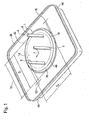
- FIG. 1 shows a schematic perspective top view of a metal cover 38 with a feedthrough device 1 according to an embodiment of the invention.
- the metal cover 38 is formed from a metal sheet 4 and has a passage opening 18, in which a sealing element 10 is pressed with its sealing element edge region 12 in an opening edge region 16 of the metal cover 38 or bounced.
- An inner diameter D I of the leadthrough opening 18 is for this purpose smaller than an outer diameter D A of the disc-shaped sealing element 10.
- a central lead-through region 14 of the sealing element 10 the boundary of which is marked here by a dashed line 42, three electrical connection elements 6 are arranged in the form of contact pins. which are partially embedded and aligned in the sealing element 10.
- the sealing element 10 can be inserted with the contact pins and a circuit board not visible here from the bottom 44 of the metal cover 38 in the passage opening 18, to which the annular edge 46 of the sealing element 10 has a chamfer 36.
- the chamfer 36 facilitates the bouncing or the pressing of the metal cover 38 into the disc-shaped sealing element 10 in the opening edge region 10.
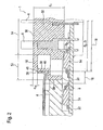
- FIG. 2 shows a schematic cross section through the feedthrough device 1 according to FIG. 1 ,
- contact pins are routed as electrical connection elements 6 from a circuit board 22 through the lead-through area 14 of the disk-shaped sealing element 10 to an upper side 50 of the lead-through area 14 of the sealing element 10, wherein the electrical connection elements 6 are partially embedded in the plastic compound 52 of the lead-through area 14.
- the electrical connection elements 6 are electrically connected as contact pins to circuit elements 54 of an electronic circuit 8 on the circuit board 22.
- the sealing element 10 adjacent to the central lead-through region 14 has a sealing element edge portion 12 which is designed as a cup-shaped sealing element portion 40, wherein the cup-shaped sealing element portion 40 has a thickness d R , which is significantly smaller than the thickness d Z of the central
- This pot-shaped sealing element region 40 consists essentially of the disc-shaped sealing element 10 and a cylindrical section 20 adjoining in the sealing element edge region 12 with an outer jacket 28. In this outer jacket 28, the cup-shaped sealing element region 40 is mounted, in which the opening edge region 16 the metal lid 38 is mounted from sheet metal 4.
- the opening edge region 16 has a curvature profile 30 which acts in an annular manner with an inner diameter D I , which is slightly smaller than the outer diameter D A of the cylindrical portion 20 in the region of the sealing element region 40, in a media-tight manner.
Landscapes
- Engineering & Computer Science (AREA)
- Architecture (AREA)
- Civil Engineering (AREA)
- Structural Engineering (AREA)
- Connector Housings Or Holding Contact Members (AREA)
- Lead Frames For Integrated Circuits (AREA)
- Insertion, Bundling And Securing Of Wires For Electric Apparatuses (AREA)
Description
- Die Erfindung betrifft eine Durchführungsvorrichtung durch ein Metallblech für mindestens ein Elektroverbindungselement zu einer elektronischen Schaltung. Dabei kann das mindestens eine Elektroverbindungselement ein Signalkabel oder ein Versorgungskabel oder ein metallischer Leiter zur Übertragung von Signalen oder Leistungsströmen aus oder in ein Gehäuse sein.
- Aus der Druckschrift
DE 10 2007 022 585 A1 ist dazu eine Leitungsdurchführung durch einen Deckel eines Tanks bekannt. Durch den Tankdeckel werden Edelstahllitzen oder elektrische Leitungen durch ein separates Dichtelement hindurchgeführt. Das separate Dichtelement ist als elastischer Steckdichtstopfen ausgebildet, der Stopföffnungen aufweisen kann, in denen die elektrischen Leitungen aufgenommen werden können. Der Steckdichtstopfen ist unmittelbar in den Tankdeckel eingesteckt und kann sich nicht selbständig lösen. Die Verbindung zwischen dem Deckel und dem Steckdichtstopfen wird mittels Klemmen oder Pressen gewährleistet. Der Steckdichtstopfen weist einen Querschnitt auf, der umlaufende Dichtflächen bereitstellt, welche die Dichtwirkung des Steckdichtstopfens in einer Durchführungsöffnung des Tankdeckels gewährleisten. - Darüber hinaus offenbart die Druckschrift
DE 23 21 154 eine abdichtende Wanddurchführung für ein Kabel, eine Rohrleitung oder dgl., die unter anderem für die Spritzwände von Kraftfahrzeugen vorgesehen sind. Die Wanddurchführung umfasst dabei eine Hülse und zwei Abdeckflansche. Mindestens einer der Abdeckflansche ist hinterschnitten ausgeführt. An einem Ende der Hülse ist eine Öffnung mit einem kegelstumpfförmigen Ansatz und einem Verriegelungsschlitz ausgebildet. Der Verriegelungsschlitz befestigt die Wanddurchführung an der Trennwand, durch die ein Kabel, eine Rohrleitung oder dgl. durchgeführt wird. Die Wanddurchführung gewährleistet eine gute Abdichtung gegen Fluide und Schallwellen. Auch in diesem zweiten Dokument wird eine separate Dichtung eingesetzt, um ein mediendichtes Abdichten zu gewährleisten und um Kabel oder Rohrleitungen durch eine Wand hindurchzuführen. - Eine herkömmliche Durchführungsanordnung ist in
DE 695 08 145 T2 offenbart. - Mit der Erfindung wird eine Durchführungsvorrichtung durch ein Metallblech für mindestens ein Elektroverbindungselement zu einer elektronischen Schaltung geschaffen. Dabei weist die Durchführungsvorrichtung einen Dichtbereich auf, der einen scheibenförmigen Dichtelementrandbereich und einen zentralen Durchführungsbereich hat. Die Durchführungsvorrichtung ist bevorzugt aus einem thermoplastische Eigenschaften aufweisenden Kunststoffmaterial gefertigt. Der zentrale Durchführungsbereich umschließt das mindestens eine Elektroverbindungselement mediendicht. Ein Öffnungsrandbereich einer Durchführungsöffnung in dem Metallblech ist mediendicht dem Dichtelementrandbereich angepasst. Der Öffnungsrandbereich der Durchführungsöffnung umschließt mit Presssitz das Elektroverbindungselement, so dass eine mediendichte Durchführung entsteht. Ein zylinderförmiger Abschnitt des Dichtelements in dem Dichtelementrandbereich weist einen Außendurchmesser auf, der größer als der Innendurchmesser der Durchführungsöffnung ist, so dass der zylinderförmige Abschnitt in der Durchführungsöffnung einen Presssitz bildet.
- Der zylinderförmige Abschnitt steht mit dem Öffnungsrandbereich der Durchführungsöffnung im Eingriff. Dazu ist die Durchführungsvorrichtung mit eingebetteten Elektroverbindungselementen in die Durchführungsöffnung eingepresst oder eingeprellt, um den Presssitz in der Durchführungsöffnung zu realisieren. Um den fertigungstechnischen Gegebenheiten bei der Herstellung aus Kunststoffmaterial Rechnung zu tragen, sind unterschiedliche Wanddicken des Kunststoffmaterials vorgesehen.
- Durch die Geometrie des Metallbleches (Einprellbereich) und deren nachgiebige Ausführung wird erreicht, dass die Durchführungsvorrichtung relativ einfach und zeitsparend montiert werden kann, ohne dass eine Nachstellung oder Nachjustierung oder eine Ausrichtung des mindestens einen Elektroverbindungselements beim Einpressen oder Einprellen des Dichtelements in die Durchführungsöffnung erforderlich wird. Durch die höhere Dicke des zentralen Durchführungsbereichs wird gewährleistet, dass die Position des mindestens einen Durchführungselements beabstandet von dem Öffnungsrandbereich stabilisiert ist.
- Das Metallblech kann als Deckel geformt sein, der in einem entsprechend vorgesehenen Bereich eines Gehäuses oder eines Behälters einsetzbar ist. Während der Öffnungsrandbereich somit nachgiebig und einpressbar ist, ist die Durchführungsvorrichtung mit dem mindestens einen Elektroverbindungselement relativ massiv und stabil, um das Elektroverbindungselement in einer vorgegebenen Position und Ausrichtung zu halten und zu fixieren.
- Außerdem ist es vorgesehen, dass der zylinderförmige Abschnitt des Dichtelements einen Positionierungsabsatz aufweist, der eine axiale Position des Öffnungsrandbereichs mit der Durchführungsöffnung auf dem zylinderförmigen Abschnitt des Dichtelements definiert.
- Erfindungsgemäß weist die Durchführungsöffnung in dem Öffnungsrandbereich einer gebördelten, kreisrunden Rand auf.
- Die Erfindung zeichnet sich dadurch aus, dass die Durchführungsvorrichtung ein einfaches Einpressen oder Einprellen in eine Durchführungsöffnung in einen nachgiebigen Randbereich eines Metallblechs, wie eines Blechdeckels beispielsweise eines Gehäuses, ermöglicht.
- Mittels der Erfindung können ohne Vorjustage und Ausrichtung von Kabeln oder Signalleitungen oder von Kontaktstiften in einem Dichtungskörper oder einem Dichtungselement Durchführungen für Metallbleche sicher und mediendicht realisiert werden.
- Die Erfindung erweitert somit den Nutzen und den Gebrauch von Durchführungen in der Kraftfahrzeugkonstruktion, da Kabel eines Kabelbaums durch Blechgehäuse und Blechdeckel hin durchgeführt werden können, was mit bisherigen Durchführungsvorrichtungen, die keine teilweise Einbettung der durchzuführenden Leitungen und Kabel bzw. Kontaktstifte in eine elastische Dichtungsmasse vorsehen, mit erheblichem Montageaufwand und Montagekosten verbunden ist.
- Die erfindungsgemäße Struktur der Durchführungsvorrichtung im Dichtelementrandbereich hat den Vorteil eines definierten Dichtungsbereichs zwischen dem Kunststoff des Dichtelementrandbereichs und dem Öffriungsrandbereich am Metallblech, so dass keine zusätzliche ringförmige Dichtung erforderlich ist und somit eine Reduzierung der eingesetzten Materialien und eine Reduktion von kritischen Schnittstellen von mediendichten Verbindungen möglich wird. Auch die Empfindlichkeit gegenüber Verunreinigungen der Schnittstellenpartner ist deutlich verringert, da einerseits das mindestens eine Elektroverbindungselement teilweise in die Kunststoffmasse eingebettet ist und andererseits nur ein einziger ringförmiger Übergang zwischen dem Metallblech der Durchführungsöffnung und dem Dichtelementrandbereich vorgesehen ist.
- Die Erfindung ermöglicht in vorteilhafter Weise Anwendungen im Kraftfahrzeugbereich, wie bei dem Einsatz für elektronische Schaltungen beispielsweise in einem Steuergerät für Fahrzeuglüfter. Dabei kann auf der Schaltungsplatine für derartige Steuergeräte die Durchführungsvorrichtung angeordnet sein, indem in vorteilhafter Weise Kontaktpins nicht nur auf der Schaltungsplatine angeordnet sind, sondern auch durch die Durchführungsvorrichtung, eingebettet in dem Durchführungsbereich des Dichtelements hindurchragen, wie es die nachfolgenden Figuren zeigen.
- Weitere Aspekte und Vorteile der Erfindung werden nunmehr anhand der beigefügten Figuren eingehender beschrieben. Hierbei zeigt:
- Fig. 1
- eine schematische perspektivische Draufsicht auf einen Metalldeckel mit einer Durchführungsvorrichtung gemäß einer Ausführungsform der Erfindung;
- Fig. 2
- einen schematischen Querschnitt durch die Durchführungsvorrichtung gemäß
Figur 1 . -
Figur 1 zeigt eine schematische perspektivische Draufsicht auf einen Metalldeckel 38 mit einer Durchführungsvorrichtung 1 gemäß einer Ausführungsform der Erfindung. Der Metalldeckel 38 ist aus einem Metallblech 4 geformt und weist eine Durchführungsöffnung 18 auf, in welche ein Dichtelement 10 mit seinem Dichtelementrandbereich 12 in einen Öffnungsrandbereich 16 des Metalldeckels 38 eingepresst bzw. eingeprellt ist. - Ein Innendurchmesser DI der Durchführungsöffnung 18 ist dazu geringer als ein Außendurchmesser DA des scheibenförmigen Dichtelements 10. In einem zentralen Durchführungsbereich 14 des Dichtelements 10, dessen Grenze hier mit einer gestrichelten Linie 42 markiert ist, sind drei Elektroverbindungselemente 6 in Form von Kontaktstiften angeordnet, die teilweise in dem Dichtelement 10 eingebettet und ausgerichtet sind.
- Das Dichtelement 10 kann mit den Kontaktstiften und einer hier nicht sichtbaren angeschlossenen Schaltungsplatine von der Unterseite 44 des Metalldeckels 38 aus in die Durchführungsöffnung 18 eingeführt werden, wozu der ringförmige Rand 46 des Dichtelements 10 eine Fase 36 aufweist. Die Fase 36 erleichtert das Einprellen oder das Einpressen des Metalldeckels 38 in das scheibenförmige Dichtelement 10 im Öffnungsrandbereich 10.
-
Figur 2 zeigt einen schematischen Querschnitt durch die Durchführungsvorrichtung 1 gemäßFigur 1 . In dieser Ausführungsform werden Kontaktstifte als Elektroverbindungselemente 6 von einer Schaltungsplatine 22 ausgehend durch den Durchführungsbereich 14 des scheibenförmigen Dichtelements 10 zu einer Oberseite 50 des Durchführungsbereichs 14 des Dichtelements 10 geführt, wobei die Elektroverbindungselemente 6 teilweise in die Kunststoffmasse 52 des Durchführungsbereichs 14 eingebettet sind. Die Elektroverbindungselemente 6 stehen als Kontaktstifte mit Schaltungselementen 54 einer elektronischen Schaltung 8 auf der Schaltungsplatine 22 elektrisch in Verbindung. - Zur mediendichten Abdichtung der Schaltungsplatine 22 weist das Dichtelement 10 neben dem zentralen Durchführungsbereich 14 einen Dichtelementrandbereich 12 auf, der als topfförmiger Dichtelementbereich 40 gestaltet ist, wobei der topfförmige Dichtelementbereich 40 eine Dicke dR aufweist, die deutlich geringer ist als die Dicke dZ des zentralen Durchführungsbereichs 14 für die Elektroverbindungselemente 6. Dieser topfförmige Dichtelementbereich 40 besteht im Wesentlichen aus dem scheibenförmigen Dichtelement 10 und einem im Dichtelementrandbereich 12 sich anschließenden zylinderförmigen Abschnitt 20 mit einem Außenmantel 28. In diesen Außenmantel 28 ist der topfförmige Dichtelementbereich 40 angebracht, in welchem der Öffnungsrandbereich 16 des Metalldeckels 38 aus Metallblech 4 montiert ist.
- Der Öffnungsrandbereich 16 weist ein Krümmungsprofil 30 auf, das ringförmig mit einem Innendurchmesser DI, welcher geringfügig kleiner als der Außendurchmesser DA des zylinderförmigen Abschnitts 20 im Bereich Dichtelementbereich 40 ist, mediendicht zusammen wirkt. Durch die Fase 36 an einem ringförmigen Außenrand 46 des scheibenförmigen Dichtelements 10 wird das Fügen des Öffnungsrandbereiches 16 in die hier gezeigte Arretierungsposition der Durchführungsvorrichtung 1 erleichtert.
- Die Erfindung ist nicht auf das hier beschriebene Ausführungsbeispiel und die darin hervorgehobenen Aspekte beschränkt; vielmehr sind innerhalb des durch die anhängenden Ansprüche angegebenen Bereichs eine Vielzahl von Abwandlungen möglich, die im Rahmen fachmännischen Handelns liegen.
Claims (6)
- Anordnung zur Durchführung mindestens eines Elektroverbindungselements (6), umfassend einen Metalldeckel (38), der aus einem Metallblech (4) geformt ist und eine Durchführungsöffnung (18) aufweist und eine Durchführungsvorrichtung, die Durchführungsvorrichtung umfassend:- ein Dichtelement (10), das einen scheibenförmigen Dichtelementrandbereich (12) aufweist und einen zentralen Durchführungsbereich (14) hat, der das mindestens eine Elektroverbindungselement (6) mediendicht umschließt,- einen Öffnungsrandbereich (16) einer Durchführungsöffnung (18) in dem Metallblech (4), die mediendicht dem Dichtelementrandbereich (12) angepasst ist,- einen zylinderförmigen Abschnitt (20) des Dichtelements (10) in dem Dichtelementrandbereich (12), dessen Außendurchmesser (DA) größer als ein Innendurchmesser (DI) der Durchführungsöffnung (18) ist, und wobei der zylinderförmige Abschnitt (20) in der Durchführungsöffnung (18) einen Presssitz aufweist, und wobei der zylinderförmige Abschnitt (20) einen topfförmigen Dichtelementbereich (40) aufweist, die in dem Öffnungsrandbereich (16) mit der Durchführungsöffnung (18) in Eingriff steht,
dadurch gekennzeichnet, dass die Durchführungsöffnung (18) in dem Öffnungsrandbereich (16) einen gebördelten, kreisrunden Rand aufweist. - Anordnung nach Anspruch 1, wobei eine Dicke (dR) des Dichtelements (10) in dem Dichtelementrandbereich (12) und in dem zylinderförmigen Abschnitt (20) geringer ist als eine Dicke (dZ) des Dichtelements (10) in dem zentralen Durchführungsbereich (14), in dem das mindestens eine Elektroverbindungselement (6) angeordnet ist.
- Anordnung nach Anspruch 1 oder Anspruch 2, wobei das Dichtelement (10) in dem zentralen Durchführungsbereich (14) einen massiven Pfropfen bildet, in dem das mindestens eine Elektroverbindungselement (6) mindestens teilweise eingebettet ist, und wobei das Dichtelement (10) in dem Dichtelementrandbereich (12) mit dem zylinderförmige Abschnitt (20) derart ausgebildet ist, dass der Dichtelementrandbereich (12) einen im Querschnitt topfförmigen Dichtelementrandbereich (12) aufweist.
- Anordnung nach Anspruch 2 oder Anspruch 3, wobei die Dicke (dZ) des Dichtelements (10) in dem zentralen Durchführungsbereich (14) mindestens ein Dreifaches einer Dicke (dR) des Dichtelements (10) in dem Dichtelementrandbereich (12) und in dem zylinderförmigen Abschnitt (20) aufweist.
- Anordnung nach einem der vorhergehenden Ansprüche, wobei der Öffnungsrandbereich (16) der Durchführungsöffnung (18) ein Krümmungsprofil (30) aufweist, das mit dem zylinderförmige Abschnitt (20) mediendicht zusammenwirkt.
- Anordnung nach einem der vorhergehenden Ansprüche, wobei der zylinderförmige Abschnitt (20) des Dichtelements (10) einen Positionierungsabsatz (32) aufweist, der eine axiale Position des Öffnungsrandbereichs (16) mit der Durchführungsöffnung (18) auf dem zylinderförmigen Abschnitt (20) definiert.
Applications Claiming Priority (2)
| Application Number | Priority Date | Filing Date | Title |
|---|---|---|---|
| DE201110080277 DE102011080277A1 (de) | 2011-08-02 | 2011-08-02 | Durchführungsvorrichtung durch ein Metallblech für mindestens ein Elektroverbindungselement zu einer elektronischen Schaltung |
| PCT/EP2012/063380 WO2013017376A2 (de) | 2011-08-02 | 2012-07-09 | Durchführungsvorrichtung durch ein metallblech für mindestens ein elektroverbindungselement zu einer elektronischen schaltung |
Publications (2)
| Publication Number | Publication Date |
|---|---|
| EP2740188A2 EP2740188A2 (de) | 2014-06-11 |
| EP2740188B1 true EP2740188B1 (de) | 2015-09-09 |
Family
ID=46516714
Family Applications (1)
| Application Number | Title | Priority Date | Filing Date |
|---|---|---|---|
| EP12735834.9A Not-in-force EP2740188B1 (de) | 2011-08-02 | 2012-07-09 | Anordnung mit einer Durchführungsvorrichtung durch ein Metallblech für mindestens ein Elektroverbindungselement zu einer elektronischen Schaltung |
Country Status (3)
| Country | Link |
|---|---|
| EP (1) | EP2740188B1 (de) |
| DE (1) | DE102011080277A1 (de) |
| WO (1) | WO2013017376A2 (de) |
Family Cites Families (8)
| Publication number | Priority date | Publication date | Assignee | Title |
|---|---|---|---|---|
| FR2181495A1 (de) | 1972-04-26 | 1973-12-07 | Peugeot & Renault | |
| DE3002140C2 (de) * | 1980-01-22 | 1983-08-25 | Fa. Carl Freudenberg, 6940 Weinheim | Kunststoffdichtring |
| US5170017A (en) * | 1991-02-15 | 1992-12-08 | Augat Inc. | Connector and method for sealed pass-through of insulated electrical conductors |
| US5493073A (en) * | 1994-05-31 | 1996-02-20 | Emerson Electric Co. | Insulating arrangement for a fused hermetic terminal assembly |
| DE10038268B4 (de) * | 2000-08-04 | 2011-05-05 | Audi Ag | Verschlussflansch für Kraftstoffbehälter |
| US6555754B2 (en) * | 2001-01-18 | 2003-04-29 | Walbro Corporation | Automotive fuel tank electrical fitting |
| DE102007022585A1 (de) | 2007-05-14 | 2008-11-27 | Robert Bosch Gmbh | Leitungsdurchführung durch einen Heiztopfdeckel eines Heiztopfs eines Reduktionsmitteltanks |
| DE102009028291A1 (de) * | 2009-08-06 | 2011-02-10 | Robert Bosch Gmbh | Kontaktierungseinrichtung für eine Testanlage |
-
2011
- 2011-08-02 DE DE201110080277 patent/DE102011080277A1/de not_active Withdrawn
-
2012
- 2012-07-09 EP EP12735834.9A patent/EP2740188B1/de not_active Not-in-force
- 2012-07-09 WO PCT/EP2012/063380 patent/WO2013017376A2/de not_active Ceased
Also Published As
| Publication number | Publication date |
|---|---|
| WO2013017376A2 (de) | 2013-02-07 |
| EP2740188A2 (de) | 2014-06-11 |
| WO2013017376A3 (de) | 2013-08-15 |
| DE102011080277A1 (de) | 2013-02-07 |
Similar Documents
| Publication | Publication Date | Title |
|---|---|---|
| DE102008052327A1 (de) | Elektromagnetisch abgeschirmter Steckverbinder | |
| DE102008022916A1 (de) | Elektromotor | |
| DE102008006340A1 (de) | Steckverbindungsanordnung mit aufgeformtem abgeschirmtem Gehäuse | |
| EP2532061B1 (de) | Elektrisches gerät mit einer durchführung eines kabels durch eine gehäusewand | |
| DE102014100142A1 (de) | Hochwasserfeste Steckerkonstruktion für eine widerstandsarme Leitung zwischen Erdstift und Gehäuse | |
| EP2845277A2 (de) | Durchführungsgehäuse | |
| WO2020229228A1 (de) | Getriebeeinheit sowie montage einer getriebeeinheit mit klemmenblock | |
| DE102014226945B4 (de) | Türverbinder für Fahrzeug | |
| DE102014205744B4 (de) | Steuergerät für ein Fahrzeugheizgerät | |
| DE102006057308B4 (de) | Leitungsbefestigungsteil | |
| DE102017209368A1 (de) | Kabeldurchführung mit abschirmenden und abdichtenden Eigenschaften | |
| EP2551978B1 (de) | Vorrichtung zur Durchführung einer elektrischen Leitung durch ein Gehäuse | |
| DE202009016970U1 (de) | Verbindungsvorrichtung | |
| EP3364504B1 (de) | Rundsteckverbinder | |
| EP2706633B1 (de) | Einsatzstück für Wandöffnungen von Installationsschränken | |
| DE29808526U1 (de) | Elektrischer Steckverbinder | |
| DE102011080277A1 (de) | Durchführungsvorrichtung durch ein Metallblech für mindestens ein Elektroverbindungselement zu einer elektronischen Schaltung | |
| EP2001092A1 (de) | Elektrisches Gerät für ein Kraftfahrzeug, insbesondere Sensor | |
| DE202019105325U1 (de) | Einschubbauteil und Bausatz für eine Kabelwanddurchführung | |
| WO1990010323A1 (de) | Kabeldurchführung mit einer elektrischen steckverbindung | |
| DE4030765A1 (de) | Armatur | |
| DE102014012739B4 (de) | Elektrischer Steckverbinder, Verbinderelement und Verwendung | |
| DE202011050660U1 (de) | Schutzgehäuse für einen elektrischen Steckverbinder | |
| EP0875736B1 (de) | Gehäuseteil mit integriertem Stecker | |
| EP2677614B1 (de) | Gehäuse zur Aufnahme eines Anhängermoduls |
Legal Events
| Date | Code | Title | Description |
|---|---|---|---|
| PUAI | Public reference made under article 153(3) epc to a published international application that has entered the european phase |
Free format text: ORIGINAL CODE: 0009012 |
|
| 17P | Request for examination filed |
Effective date: 20140303 |
|
| AK | Designated contracting states |
Kind code of ref document: A2 Designated state(s): AL AT BE BG CH CY CZ DE DK EE ES FI FR GB GR HR HU IE IS IT LI LT LU LV MC MK MT NL NO PL PT RO RS SE SI SK SM TR |
|
| DAX | Request for extension of the european patent (deleted) | ||
| GRAP | Despatch of communication of intention to grant a patent |
Free format text: ORIGINAL CODE: EPIDOSNIGR1 |
|
| INTG | Intention to grant announced |
Effective date: 20150312 |
|
| GRAS | Grant fee paid |
Free format text: ORIGINAL CODE: EPIDOSNIGR3 |
|
| GRAA | (expected) grant |
Free format text: ORIGINAL CODE: 0009210 |
|
| AK | Designated contracting states |
Kind code of ref document: B1 Designated state(s): AL AT BE BG CH CY CZ DE DK EE ES FI FR GB GR HR HU IE IS IT LI LT LU LV MC MK MT NL NO PL PT RO RS SE SI SK SM TR |
|
| REG | Reference to a national code |
Ref country code: GB Ref legal event code: FG4D Free format text: NOT ENGLISH |
|
| REG | Reference to a national code |
Ref country code: AT Ref legal event code: REF Ref document number: 748831 Country of ref document: AT Kind code of ref document: T Effective date: 20150915 Ref country code: CH Ref legal event code: EP |
|
| REG | Reference to a national code |
Ref country code: IE Ref legal event code: FG4D Free format text: LANGUAGE OF EP DOCUMENT: GERMAN |
|
| REG | Reference to a national code |
Ref country code: DE Ref legal event code: R096 Ref document number: 502012004477 Country of ref document: DE |
|
| REG | Reference to a national code |
Ref country code: NL Ref legal event code: MP Effective date: 20150909 |
|
| PG25 | Lapsed in a contracting state [announced via postgrant information from national office to epo] |
Ref country code: NO Free format text: LAPSE BECAUSE OF FAILURE TO SUBMIT A TRANSLATION OF THE DESCRIPTION OR TO PAY THE FEE WITHIN THE PRESCRIBED TIME-LIMIT Effective date: 20151209 Ref country code: LV Free format text: LAPSE BECAUSE OF FAILURE TO SUBMIT A TRANSLATION OF THE DESCRIPTION OR TO PAY THE FEE WITHIN THE PRESCRIBED TIME-LIMIT Effective date: 20150909 Ref country code: LT Free format text: LAPSE BECAUSE OF FAILURE TO SUBMIT A TRANSLATION OF THE DESCRIPTION OR TO PAY THE FEE WITHIN THE PRESCRIBED TIME-LIMIT Effective date: 20150909 Ref country code: GR Free format text: LAPSE BECAUSE OF FAILURE TO SUBMIT A TRANSLATION OF THE DESCRIPTION OR TO PAY THE FEE WITHIN THE PRESCRIBED TIME-LIMIT Effective date: 20151210 Ref country code: FI Free format text: LAPSE BECAUSE OF FAILURE TO SUBMIT A TRANSLATION OF THE DESCRIPTION OR TO PAY THE FEE WITHIN THE PRESCRIBED TIME-LIMIT Effective date: 20150909 |
|
| REG | Reference to a national code |
Ref country code: LT Ref legal event code: MG4D |
|
| PG25 | Lapsed in a contracting state [announced via postgrant information from national office to epo] |
Ref country code: RS Free format text: LAPSE BECAUSE OF FAILURE TO SUBMIT A TRANSLATION OF THE DESCRIPTION OR TO PAY THE FEE WITHIN THE PRESCRIBED TIME-LIMIT Effective date: 20150909 Ref country code: SE Free format text: LAPSE BECAUSE OF FAILURE TO SUBMIT A TRANSLATION OF THE DESCRIPTION OR TO PAY THE FEE WITHIN THE PRESCRIBED TIME-LIMIT Effective date: 20150909 Ref country code: HR Free format text: LAPSE BECAUSE OF FAILURE TO SUBMIT A TRANSLATION OF THE DESCRIPTION OR TO PAY THE FEE WITHIN THE PRESCRIBED TIME-LIMIT Effective date: 20150909 Ref country code: ES Free format text: LAPSE BECAUSE OF FAILURE TO SUBMIT A TRANSLATION OF THE DESCRIPTION OR TO PAY THE FEE WITHIN THE PRESCRIBED TIME-LIMIT Effective date: 20150909 |
|
| PG25 | Lapsed in a contracting state [announced via postgrant information from national office to epo] |
Ref country code: NL Free format text: LAPSE BECAUSE OF FAILURE TO SUBMIT A TRANSLATION OF THE DESCRIPTION OR TO PAY THE FEE WITHIN THE PRESCRIBED TIME-LIMIT Effective date: 20150909 |
|
| PG25 | Lapsed in a contracting state [announced via postgrant information from national office to epo] |
Ref country code: CZ Free format text: LAPSE BECAUSE OF FAILURE TO SUBMIT A TRANSLATION OF THE DESCRIPTION OR TO PAY THE FEE WITHIN THE PRESCRIBED TIME-LIMIT Effective date: 20150909 Ref country code: EE Free format text: LAPSE BECAUSE OF FAILURE TO SUBMIT A TRANSLATION OF THE DESCRIPTION OR TO PAY THE FEE WITHIN THE PRESCRIBED TIME-LIMIT Effective date: 20150909 Ref country code: SK Free format text: LAPSE BECAUSE OF FAILURE TO SUBMIT A TRANSLATION OF THE DESCRIPTION OR TO PAY THE FEE WITHIN THE PRESCRIBED TIME-LIMIT Effective date: 20150909 Ref country code: IS Free format text: LAPSE BECAUSE OF FAILURE TO SUBMIT A TRANSLATION OF THE DESCRIPTION OR TO PAY THE FEE WITHIN THE PRESCRIBED TIME-LIMIT Effective date: 20160109 |
|
| PG25 | Lapsed in a contracting state [announced via postgrant information from national office to epo] |
Ref country code: RO Free format text: LAPSE BECAUSE OF FAILURE TO SUBMIT A TRANSLATION OF THE DESCRIPTION OR TO PAY THE FEE WITHIN THE PRESCRIBED TIME-LIMIT Effective date: 20150909 Ref country code: PL Free format text: LAPSE BECAUSE OF FAILURE TO SUBMIT A TRANSLATION OF THE DESCRIPTION OR TO PAY THE FEE WITHIN THE PRESCRIBED TIME-LIMIT Effective date: 20150909 Ref country code: PT Free format text: LAPSE BECAUSE OF FAILURE TO SUBMIT A TRANSLATION OF THE DESCRIPTION OR TO PAY THE FEE WITHIN THE PRESCRIBED TIME-LIMIT Effective date: 20160111 |
|
| REG | Reference to a national code |
Ref country code: DE Ref legal event code: R097 Ref document number: 502012004477 Country of ref document: DE |
|
| PLBE | No opposition filed within time limit |
Free format text: ORIGINAL CODE: 0009261 |
|
| STAA | Information on the status of an ep patent application or granted ep patent |
Free format text: STATUS: NO OPPOSITION FILED WITHIN TIME LIMIT |
|
| REG | Reference to a national code |
Ref country code: FR Ref legal event code: PLFP Year of fee payment: 5 |
|
| 26N | No opposition filed |
Effective date: 20160610 |
|
| PG25 | Lapsed in a contracting state [announced via postgrant information from national office to epo] |
Ref country code: SI Free format text: LAPSE BECAUSE OF FAILURE TO SUBMIT A TRANSLATION OF THE DESCRIPTION OR TO PAY THE FEE WITHIN THE PRESCRIBED TIME-LIMIT Effective date: 20150909 Ref country code: DK Free format text: LAPSE BECAUSE OF FAILURE TO SUBMIT A TRANSLATION OF THE DESCRIPTION OR TO PAY THE FEE WITHIN THE PRESCRIBED TIME-LIMIT Effective date: 20150909 |
|
| PG25 | Lapsed in a contracting state [announced via postgrant information from national office to epo] |
Ref country code: BE Free format text: LAPSE BECAUSE OF NON-PAYMENT OF DUE FEES Effective date: 20160731 |
|
| REG | Reference to a national code |
Ref country code: CH Ref legal event code: PL |
|
| PG25 | Lapsed in a contracting state [announced via postgrant information from national office to epo] |
Ref country code: MC Free format text: LAPSE BECAUSE OF FAILURE TO SUBMIT A TRANSLATION OF THE DESCRIPTION OR TO PAY THE FEE WITHIN THE PRESCRIBED TIME-LIMIT Effective date: 20150909 |
|
| PG25 | Lapsed in a contracting state [announced via postgrant information from national office to epo] |
Ref country code: LI Free format text: LAPSE BECAUSE OF NON-PAYMENT OF DUE FEES Effective date: 20160731 Ref country code: CH Free format text: LAPSE BECAUSE OF NON-PAYMENT OF DUE FEES Effective date: 20160731 |
|
| REG | Reference to a national code |
Ref country code: IE Ref legal event code: MM4A |
|
| REG | Reference to a national code |
Ref country code: FR Ref legal event code: PLFP Year of fee payment: 6 |
|
| PG25 | Lapsed in a contracting state [announced via postgrant information from national office to epo] |
Ref country code: IE Free format text: LAPSE BECAUSE OF NON-PAYMENT OF DUE FEES Effective date: 20160709 |
|
| PG25 | Lapsed in a contracting state [announced via postgrant information from national office to epo] |
Ref country code: LU Free format text: LAPSE BECAUSE OF NON-PAYMENT OF DUE FEES Effective date: 20160709 |
|
| PG25 | Lapsed in a contracting state [announced via postgrant information from national office to epo] |
Ref country code: SM Free format text: LAPSE BECAUSE OF FAILURE TO SUBMIT A TRANSLATION OF THE DESCRIPTION OR TO PAY THE FEE WITHIN THE PRESCRIBED TIME-LIMIT Effective date: 20150909 Ref country code: CY Free format text: LAPSE BECAUSE OF FAILURE TO SUBMIT A TRANSLATION OF THE DESCRIPTION OR TO PAY THE FEE WITHIN THE PRESCRIBED TIME-LIMIT Effective date: 20150909 Ref country code: HU Free format text: LAPSE BECAUSE OF FAILURE TO SUBMIT A TRANSLATION OF THE DESCRIPTION OR TO PAY THE FEE WITHIN THE PRESCRIBED TIME-LIMIT; INVALID AB INITIO Effective date: 20120709 |
|
| PG25 | Lapsed in a contracting state [announced via postgrant information from national office to epo] |
Ref country code: MT Free format text: LAPSE BECAUSE OF FAILURE TO SUBMIT A TRANSLATION OF THE DESCRIPTION OR TO PAY THE FEE WITHIN THE PRESCRIBED TIME-LIMIT Effective date: 20150909 Ref country code: MK Free format text: LAPSE BECAUSE OF FAILURE TO SUBMIT A TRANSLATION OF THE DESCRIPTION OR TO PAY THE FEE WITHIN THE PRESCRIBED TIME-LIMIT Effective date: 20150909 |
|
| REG | Reference to a national code |
Ref country code: FR Ref legal event code: PLFP Year of fee payment: 7 |
|
| PG25 | Lapsed in a contracting state [announced via postgrant information from national office to epo] |
Ref country code: BG Free format text: LAPSE BECAUSE OF FAILURE TO SUBMIT A TRANSLATION OF THE DESCRIPTION OR TO PAY THE FEE WITHIN THE PRESCRIBED TIME-LIMIT Effective date: 20150909 |
|
| REG | Reference to a national code |
Ref country code: AT Ref legal event code: MM01 Ref document number: 748831 Country of ref document: AT Kind code of ref document: T Effective date: 20170709 |
|
| PG25 | Lapsed in a contracting state [announced via postgrant information from national office to epo] |
Ref country code: TR Free format text: LAPSE BECAUSE OF FAILURE TO SUBMIT A TRANSLATION OF THE DESCRIPTION OR TO PAY THE FEE WITHIN THE PRESCRIBED TIME-LIMIT Effective date: 20150909 Ref country code: AL Free format text: LAPSE BECAUSE OF FAILURE TO SUBMIT A TRANSLATION OF THE DESCRIPTION OR TO PAY THE FEE WITHIN THE PRESCRIBED TIME-LIMIT Effective date: 20150909 |
|
| PG25 | Lapsed in a contracting state [announced via postgrant information from national office to epo] |
Ref country code: AT Free format text: LAPSE BECAUSE OF NON-PAYMENT OF DUE FEES Effective date: 20170709 |
|
| PGFP | Annual fee paid to national office [announced via postgrant information from national office to epo] |
Ref country code: IT Payment date: 20210730 Year of fee payment: 10 Ref country code: FR Payment date: 20210722 Year of fee payment: 10 |
|
| PGFP | Annual fee paid to national office [announced via postgrant information from national office to epo] |
Ref country code: DE Payment date: 20210924 Year of fee payment: 10 Ref country code: GB Payment date: 20210722 Year of fee payment: 10 |
|
| REG | Reference to a national code |
Ref country code: DE Ref legal event code: R119 Ref document number: 502012004477 Country of ref document: DE |
|
| GBPC | Gb: european patent ceased through non-payment of renewal fee |
Effective date: 20220709 |
|
| PG25 | Lapsed in a contracting state [announced via postgrant information from national office to epo] |
Ref country code: FR Free format text: LAPSE BECAUSE OF NON-PAYMENT OF DUE FEES Effective date: 20220731 |
|
| PG25 | Lapsed in a contracting state [announced via postgrant information from national office to epo] |
Ref country code: GB Free format text: LAPSE BECAUSE OF NON-PAYMENT OF DUE FEES Effective date: 20220709 Ref country code: DE Free format text: LAPSE BECAUSE OF NON-PAYMENT OF DUE FEES Effective date: 20230201 |
|
| PG25 | Lapsed in a contracting state [announced via postgrant information from national office to epo] |
Ref country code: IT Free format text: LAPSE BECAUSE OF NON-PAYMENT OF DUE FEES Effective date: 20220709 |