EP2551978B1 - Vorrichtung zur Durchführung einer elektrischen Leitung durch ein Gehäuse - Google Patents
Vorrichtung zur Durchführung einer elektrischen Leitung durch ein Gehäuse Download PDFInfo
- Publication number
- EP2551978B1 EP2551978B1 EP11006298.1A EP11006298A EP2551978B1 EP 2551978 B1 EP2551978 B1 EP 2551978B1 EP 11006298 A EP11006298 A EP 11006298A EP 2551978 B1 EP2551978 B1 EP 2551978B1
- Authority
- EP
- European Patent Office
- Prior art keywords
- housing
- locking
- connector
- assembly
- assembly plate
- Prior art date
- Legal status (The legal status is an assumption and is not a legal conclusion. Google has not performed a legal analysis and makes no representation as to the accuracy of the status listed.)
- Active
Links
Images


Classifications
-
- H—ELECTRICITY
- H02—GENERATION; CONVERSION OR DISTRIBUTION OF ELECTRIC POWER
- H02G—INSTALLATION OF ELECTRIC CABLES OR LINES, OR OF COMBINED OPTICAL AND ELECTRIC CABLES OR LINES
- H02G3/00—Installations of electric cables or lines or protective tubing therefor in or on buildings, equivalent structures or vehicles
- H02G3/22—Installations of cables or lines through walls, floors or ceilings, e.g. into buildings
-
- H—ELECTRICITY
- H02—GENERATION; CONVERSION OR DISTRIBUTION OF ELECTRIC POWER
- H02G—INSTALLATION OF ELECTRIC CABLES OR LINES, OR OF COMBINED OPTICAL AND ELECTRIC CABLES OR LINES
- H02G15/00—Cable fittings
- H02G15/013—Sealing means for cable inlets
-
- H—ELECTRICITY
- H02—GENERATION; CONVERSION OR DISTRIBUTION OF ELECTRIC POWER
- H02G—INSTALLATION OF ELECTRIC CABLES OR LINES, OR OF COMBINED OPTICAL AND ELECTRIC CABLES OR LINES
- H02G15/00—Cable fittings
- H02G15/02—Cable terminations
- H02G15/025—Cable terminations for coaxial cables or hollow conductors
Definitions
- the present invention relates to an assembly according to the preamble of claim 1.
- Such assemblies are used, for example, in batteries that are used for the voltage supply in motor vehicles with hybrid drives or electric drives.
- An assembly according to the preamble of claim 1 is from EP 1 289 086 A1 known. Further prior art is known from EP 2 337 164 A1 , DE 195 26 927 A1 , DE 1 285 591 B , DE 197 43 710 A1 and U.S. 3,728,470 A .
- the present invention is based on the object of creating an assembly that allows two shielded lines to be fixed to a housing by twisting them and at the same time to connect their shields to the housing, avoiding the lines being mixed up, so that in a particularly simple manner a safe implementation for the two lines is made possible.
- each connector has a locking section which can be inserted into the feed-through opening and locked on the mounting plate by subsequent rotation.
- the device can therefore be assembled and locked particularly easily in the manner of a bayonet catch.
- the mounting plate and the connectors can each be formed in one piece.
- the mounting plate and the connectors can be produced simply and inexpensively, for example by injection molding.
- the mounting plate and the connectors can be made of plastic.
- Plastic is an electrical insulator and is therefore particularly suitable as a material for the mounting plate and the connectors.
- the mounting plate preferably has latching elements on a side facing the housing for fixing the mounting plate on the housing. This allows the mounting plate to be attached to the housing without great effort.
- the latching elements are particularly preferably arranged offset from one another around the feed-through opening and can be passed through the housing opening.
- the offset arrangement of the locking elements results in a better distribution of the forces on the locking elements when the mounting plate is fixed on the housing.
- each latching element has a radially outwardly extending latching lug that can be latched onto the second side of the housing.
- the mounting plate can be held particularly well on the housing by means of the latching lugs.
- a spring washer preferably captive, is arranged on the side of the mounting plate facing the housing, in particular concentric to each feed-through opening.
- the mounting plate can be supported on the first side of the housing by the spring washers, so that the mounting plate is pressed away from the housing and the connectors.
- the spring washers therefore cause a tension between the connectors and the mounting plate, so that any play that may be present between the mounting plate and the housing or between the connectors and the housing can be reduced.
- the spring washers can be made of stainless steel, for example.
- a groove is provided as a receptacle for each spring washer on the side of the mounting plate facing the housing.
- the groove can prevent the spring washer from slipping along the side of the mounting plate facing the housing while the mounting plate is being attached to the housing, so that the mounting plate can be attached to the housing more easily.
- the latching lugs of the latching elements arranged around the lead-through openings are preferably guided radially outward to such an extent that they at least partially protrude beyond the groove.
- the locking lugs thus form a loss protection for the spring washers.
- each locking section has at least one locking element which is brought into engagement with the mounting plate, in particular with the side of the mounting plate facing away from the housing can be.
- the connector can be locked to the mounting plate in a simple manner by means of the locking element.
- each locking element protrudes radially outward on the locking section and a channel is provided in a wall of the mounting plate that delimits the respective feed-through opening, in which the locking element is guided when the locking section is inserted into the feed-through opening.
- a run-on bevel is provided for each locking element, which starts at the exit of the respective channel and extends in the circumferential direction of the respective feed-through opening, so that the locking element slides up the run-on bevel and thereby pulls the mounting plate and the respective connector together. when the fully inserted connector is twisted to lock it on the mounting plate.
- each run-up bevel has a stop for the respective locking element at its end facing away from the channel outlet.
- the stop limits the angle of rotation by which the respective connector can be rotated maximally.
- Each run-up bevel can have a latching recess, in particular located in front of the stop, for the respective locking element in order to fix the respective locking element and to prevent the connector from being unintentionally turned back.
- Each connector is thus permanently and securely locked to the mounting plate.
- the mounting plate has first coding means in the area of the feed-through openings and the locking sections have second coding means, the respective first and second coding means interacting with one another in such a way that the locking sections can only be locked on the mounting plate when the first and second coding means are complementary to one another and that the The first and second coding means block the insertion of the locking sections into the respective lead-through opening and / or their subsequent rotation if the first and second coding means are not designed to be complementary to one another.
- the lead-through openings and the locking sections interact in the manner of a key-lock combination, so that only the "matching" locking section can be inserted into the lead-through opening and locked to the mounting plate.
- a "wrong" locking section cannot be locked with the mounting plate, comparable to a key that is inserted into a wrong lock.
- the coding means are particularly advantageous when different connectors are to be attached to them.
- the coding means can ensure that each connector can only be inserted and locked into the provided feed-through opening, since using the coding means - as is known with keys and locks - only one matching locking section / feed-through opening combination can be implemented.
- the coding means can be formed, for example, in that the lead-through openings have different diameters and the locking sections of the connectors have correspondingly adapted outer diameters.
- the channels in a mounting plate and the locking elements of the locking sections can also be provided as coding means designed to be complementary to one another, with the depth and width of the respective channel corresponding to the height and width of the respective locking element.
- Another connector with a locking section on which a locking element that is too wide or too high is arranged cannot therefore be inserted into the lead-through opening.
- a respective recess in particular on the side of the mounting plate facing the housing, can be formed in the area of the lead-through opening and a raised portion can be provided on the locking section of a respective connector, which is received in the cut-out when the locking section is inserted into the lead-through opening can move in the recess when the connector is rotated.
- An unsuitable connector in which there is an excessively large elevation on the locking section cannot consequently be completely inserted into the lead-through opening and locked, since the excessively large elevation cannot be received in the recess.
- the recess and the elevation thus also form a complementary pair of coding means.
- each connector has a flange section behind the locking section, which has a circumferential groove on the side facing the locking section, based on the direction of insertion of the connector into the lead-through opening for a seal.
- the seal can consist of silicone.
- the flange section can serve as a stop by which the depth of insertion of the locking section into the feed-through opening is limited.
- each connector - based on the direction of insertion of the connector into the feed-through opening - has a contacting section behind the locking section, in which at least one electrically conductive ferrule is arranged for contacting a shield of the respective electrical line. The area of the line in which the shielding is contacted is thus protected by the contacting section.
- An electrically conductive inner ferrule is preferably arranged beneath each shield.
- an electrically conductive outer ferrule is arranged outside the shield and outside the inner ferrule. As a result, the respective shield can be contacted particularly well.
- the two respective ferrules are particularly preferably crimped together so that permanent electrical contact for shielding can be established in a simple manner.
- the two respective ferrules can each be made from stainless steel.
- an electrically conductive contact element is provided for electrically connecting the housing to the ferrule, in particular to the outer ferrule.
- the contact element can also be made of stainless steel.
- each contact element has an annular base body which surrounds the locking section.
- At least one first contact arm can be formed on the base body, which is led away from the base body in such a way that the first contact arm extends into the contacting section, in particular through an opening formed in the flange section, and the ferrule arranged there, in particular the outer ferrule, electrically contacted.
- second contact arms are formed on the base body, which are guided from the base body to the housing, so that the second contact arms make electrical contact with the second side of the housing when the connector is locked on the mounting plate.
- a washer that surrounds the electrical line, in particular its sheathing is arranged behind the at least one respective ferrule, which is preferably made of stainless steel, within each contacting section - based on the direction of insertion of the connector into the feed-through opening.
- a cable seal which surrounds the electrical line, in particular its sheathing, is arranged behind the washer within the contacting section and is preferably made of silicone.
- a sealing cap can be placed and / or in each case be clipped in, the sealing cap surrounding the contacting section and the electrical line led out of the rear end.
- the respective sealing cap can for example consist of plastic.
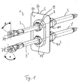
- the device 1 shown is provided for leading two electrical lines 3, 3 'through a housing 5, for example a battery.
- the device 1 comprises a mounting plate 7 which is attached to the inside 5a of the housing 5.
- the mounting plate 7 there are two lead-through openings 9, 9 '(cf. Fig. 2 ) which are aligned with the housing openings provided on the housing 5.
- One of the lines 3, 3 ' is passed through each feed-through opening 9, 9'.
- Fig. 1 the upper part of the mounting plate 7 and the upper connector 11 and apply accordingly to the lower part of the mounting plate 7 and the lower connector 11 '.
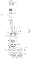
- Fig. 2 the housing 5 is shown as a dashed line in order to make it clear which components of the device 1 are arranged on the inside 5a and which components are arranged on the outside 5b of the housing 5.
- the mounting plate 7 has locking elements 17 on its side 15 facing the housing 5 (cf. Figures 3 and 4 ), by means of which the mounting plate 7 can be fixed on the housing 5.
- the latching elements 17 are arranged offset to one another around the lead-through opening 9 in such a way that they are guided through the respective housing opening provided on the housing 5 and can snap into place behind the housing 5.
- each latching element 17 has a latching lug 19 on its end facing away from the mounting plate side 15, which extends radially outward and which can engage with the outside 5b of the housing 5 (cf. Fig. 4 ) to secure the mounting plate 7 to the housing 5.
- a spring washer 21 is arranged concentrically to the feed-through opening 9 and is received in a groove 23 running in the circumferential direction around the feed-through opening 9.
- the groove 23 runs around the latching elements 17 and is at least partially protruded from the latching lugs 19, which thus form a protection against loss for the spring washer 21.
- the spring washer 21 To mount the spring washer 21 on the mounting plate 7, the spring washer 21 must be pressed over the locking lugs 19.
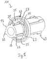
- the connector 11 has a locking portion 13 which can be inserted into the feed-through opening 9 of the mounting plate 7 and then rotated with respect to the mounting plate 7, about which the connector 11, as shown in FIG Fig. 1 can be seen to lock with the mounting plate 7.
- three locking elements 25 are arranged at the front end of the locking section 13, which protrude radially outward.
- a channel 27 is provided for each locking element 25 in a wall of the mounting plate 7 delimiting the feed-through opening 9 (cf. Fig. 3 ), into which the respective locking element 25 must be inserted when the locking section 13 is inserted into the feed-through opening 9.
- a ramp extending in the circumferential direction of the feed-through opening 9 is designed as a bevel 31 at each exit of a channel 27 on the side 29 of the mounting plate 7 facing away from the housing, which begins at the respective channel outlet and is led away from the channel outlet in the circumferential direction.
- the run-on slope 31 ends with a stop 33 for the locking element 25.
- a latching recess 35 is formed in front of the stop 33.
- the connector 11 has - based on the direction of insertion of the connector 11 into the feed-through opening 9 - behind the locking section 13 a flange section 37 which, on its side facing the locking section 13, has a circumferential groove 39 which is provided for receiving a seal 41 which comes to rest on the outside of the housing 5b and seals the locking section 13 from the environment.
- the connector 11 has a contacting section 43 behind the flange section 37, in which a sheathing, not shown, of the line 3 is stripped and a shielding, also not shown, of the line 3, which forms the conductive core the line 3 surrounds, is electrically contacted.
- an electrically conductive inner ferrule 45 is arranged below the shield and an outer ferrule 47 surrounding the inner ferrule 45 is arranged outside the shield. The two ferrules 45, 47 are crimped together so that they make electrical contact with the shielding between them reliably and permanently.
- an electrically conductive contact element 49 is provided, which electrically connects the outer ferrule 47 to the outer side 5 b of the housing 5 in order to short-circuit the shield with the housing 5.
- the contact element 49 has an annular base body 51 which is placed on the locking section 13.
- First contact arms 53 are formed on the base body 51 and protrude through openings 55 provided in the flange section 37 and make electrical contact with the outer ferrule 47.
- second contact arms 57 are arranged on the base body 51, which come to rest on the outside 5b of the housing 5 when the connector 11 is locked to the mounting plate 7, so that the housing is electrically contacted via the second contact arms and the shield is short-circuited with the housing becomes.
- a washer 59 is arranged inside the contacting section 43 behind the two ferrules 45, 47 as seen in the insertion direction of the connector 11 into the lead-through opening 9.
- a cable seal 61 is provided behind the washer 59, which is also arranged within the contacting section 43.
- the washer 59 and the cable seal 61 each surround the electrical line 3.
- the cable seal 61 seals the interior of the contacting section 43 from the environment.
- a sealing cap 63 is also provided, which is pushed onto the rear end of the contacting section 43 and clipped onto the contacting section 43.
- the device 1 described by way of example is provided for leading two lines 3, 3 ′ through the housing 5.
- the lines 3, 3 'can for example differ with regard to their intended use, which is why different connectors 11 and 11 'can be used to differentiate.
- one line 3 can be a plus line and the other line 3 'can be a minus line.
- recesses 65 are provided in the area of the respective lead-through opening 9 on the side 15 of the mounting plate 7 facing the housing 5, which interact with elevations 67 formed on the locking section 13 of the connector 11. Correctly dimensioned elevations 67 are received in the recesses 65 when the locking section 13 is inserted into the feed-through opening 9 and guided in the recesses 65 when the connector 11 is rotated. If, on the other hand, a connector 11 ′ has oversized elevations, it cannot be completely inserted into the feed-through opening 9, since its elevations cannot be received in the recesses 65. It is thus achieved that only a suitable connector 11 can be arranged on the feed-through opening 9.
- the locking elements 25 of the connector 11 can have a smaller width and / or a smaller height than those of the connector 11 '. Since the channels 27 are as deep and as wide as the locking elements 25 of the connector 11 are high and wide only the connector 11, but not the connector 11 ′, can be inserted into the feed-through opening 9.
- the diameter of the passage opening 9 located above can be larger than the diameter of the passage opening 9 'located below, and accordingly the locking section 13 of the connector 11 can have a larger outer diameter than the locking section 13' of the connector 11 '. The connector 11 therefore does not fit into the lead-through opening 9 '.
- markings 69 can be formed on the side 29 of the mounting plate 7 facing away from the housing, which indicate that the respective locking section 13, 13 'is rotated as far as the stop 33 and is thus correctly locked.
- the mounting plate 7 is clipped onto the housing 5.
- the two ferrules 45, 47, the washer 59 and the cable seal 61 are attached to the electrical line 3, 3 ′ and then arranged in the contacting section 43.
- the sealing cap 63 is arranged at the rear end of the connector 11, 11 '.
- the gasket 41 is attached to the flange portion 37 and the contact element 49 is placed on the locking portion 13.
- the line 3, 3 ' is then introduced from the outside 5b of the housing 5 into the respective feed-through opening 9, 9' of the mounting plate 7.
- the connector 11, 11 ′ is then locked to the mounting plate 7.
- FIG. 1 shows, in the example shown, a cable lug 71, 71 'is arranged at the end of the line 9, 9'.
- the cable lug 71, 71 ' is just one possible example of an electrical connector.
- the electrical connector can also be formed by a socket or plug-shaped contact part.
Landscapes
- Engineering & Computer Science (AREA)
- Architecture (AREA)
- Civil Engineering (AREA)
- Structural Engineering (AREA)
- Details Of Connecting Devices For Male And Female Coupling (AREA)
- Connector Housings Or Holding Contact Members (AREA)
Description
- Die vorliegende Erfindung betrifft eine Baugruppe gemäß dem Oberbegriff des Anspruchs 1.
- Derartige Baugruppen kommen beispielweise bei Batterien zum Einsatz, die für die Spannungsversorgung in Kraftfahrzeugen mit Hybridantrieb oder Elektroantrieb verwendet werden.
- Eine Baugruppe nach dem Oberbegriff des Anspruchs 1 ist aus der
EP 1 289 086 A1 bekannt. Weiterer Stand der Technik ist bekannt ausEP 2 337 164 A1 ,DE 195 26 927 A1 ,DE 1 285 591 B ,DE 197 43 710 A1 undUS 3 728 470 A . - Der vorliegenden Erfindung liegt die Aufgabe zu Grunde, eine Baugruppe zu schaffen, die es erlaubt, durch Verdrehen zwei abgeschirmte Leitungen an einem Gehäuse festzulegen und zugleich deren Abschirmungen mit dem Gehäuse zu verbinden, wobei ein Vertauschen der Leitungen vermieden wird, sodass auf besonders einfache Weise eine sichere Durchführung für die beiden Leitungen ermöglicht wird.
- Die Aufgabe wird durch eine Baugruppe mit den Merkmalen des Anspruchs 1 gelöst. Bevorzugte Ausführungsformen der Erfindung sind in den abhängigen Ansprüchen angegeben.
- Erfindungsgemäß weist jeder Konnektor einen Verriegelungsabschnitt auf, welcher in die Durchführungsöffnung einsteckbar und durch anschließende Verdrehung an der Montageplatte verriegelbar ist. Die Vorrichtung lässt sich daher nach Art eines Bajonettverschlusses besonders einfach zusammensetzen und verriegeln.
- Die Montageplatte und die Konnektoren können jeweils einstückig ausgebildet sein. Dadurch können die Montageplatte und die Konnektoren einfach und kostengünstig hergestellt werden, zum Beispiel durch Spritzgießen.
- Die Montageplatte und die Konnektoren können aus Kunststoff bestehen. Kunststoff ist ein elektrischer Isolator und eignet sich daher besonders gut als Material für die Montageplatte und die Konnektoren.
- Bevorzugt weist die Montageplatte an einer dem Gehäuse zugewandten Seite Rastelemente zur Festlegung der Montageplatte am Gehäuse auf. Dadurch kann die Montageplatte ohne großen Aufwand am Gehäuse befestigt werden.
- Besonders bevorzugt sind die Rastelemente um die Durchführungsöffnung herum versetzt zueinander angeordnet und durch die Gehäuseöffnung durchführbar. Durch die versetzte Anordnung der Rastelemente ergibt sich eine bessere Verteilung der Kräfte auf die Rastelemente, wenn die Montageplatte am Gehäuse fixiert ist.
- Insbesondere weist jedes Rastelement eine sich nach radial außen erstreckende, an der zweiten Seite des Gehäuses einrastbare Rastnase auf. Durch die eingerasteten Rastnasen kann die Montageplatte besonders gut am Gehäuse gehalten werden.
- Nach einer bevorzugten Weiterbildung der Erfindung ist eine Federscheibe, bevorzugt verliersicher, an der dem Gehäuse zugewandten Seite der Montageplatte angeordnet, insbesondere konzentrisch zu jeder Durchführungsöffnung. Durch die Federscheiben kann die Montageplatte an der ersten Seite des Gehäuses abgestützt werden, so dass die Montageplatte vom Gehäuse und von den Konnektoren weggedrückt wird. Die Federscheiben bewirken daher eine Spannung zwischen den Konnektoren und der Montageplatte, so dass ein zwischen der Montageplatte und dem Gehäuse bzw. den Konnektoren und dem Gehäuse möglicherweise vorhandenes Spiel verringert werden kann.
- Die Federscheiben können beispielsweise aus CrNi-Stahl ausgebildet sein.
- Nach einer bevorzugten Weiterbildung der Erfindung ist eine Nut als Aufnahme für jede Federscheibe an der dem Gehäuse zugewandten Seite der Montageplatte vorgesehen. Durch die Nut kann verhindert werden, dass die Federscheibe entlang der dem Gehäuse zugewandten Seite der Montageplatte verrutscht, während die Montageplatte am Gehäuse angebracht wird, so dass sich die Montageplatte einfacher am Gehäuse befestigen lässt.
- Vorzugsweise sind die Rastnasen der um die Durchführungsöffnungen herum angeordneten Rastelemente derart weit nach radial außen geführt, dass diese die Nut zumindest teilweise überragen. Die Rastnasen bilden somit eine Verliersicherung für die Federscheiben.
- Erfindungsgemäß weist jeder Verriegelungsabschnitt zumindest ein Verriegelungselement auf, welches mit der Montageplatte, insbesondere mit der vom Gehäuse abgewandten Seite der Montageplatte, in Eingriff gebracht werden kann. Durch das Verriegelungselement lässt sich der Konnektor auf einfache Weise mit der Montageplatte verriegeln.
- Erfindungsgemäß steht jedes Verriegelungselement am Verriegelungsabschnitt nach radial außen hervor und in einer die jeweilige Durchführungsöffnung begrenzenden Wand der Montageplatte ist ein Kanal vorgesehen, in dem das Verriegelungselement geführt wird, wenn der Verriegelungsabschnitt in die Durchführungsöffnung eingesteckt wird. Auf diese Weise kann herstellungstechnisch besonders einfach ein in die Durchführungsöffnungen einführbarer und mit der Montageplatte verriegelbarer Verriegelungsabschnitt realisiert werden.
- Erfindungsgemäß ist an der vom Gehäuse abgewandten Seite der Montageplatte eine Anlaufschräge für jedes Verriegelungselement vorgesehen, die am Ausgang des jeweiligen Kanals beginnt und sich in Umfangsrichtung der jeweiligen Durchführungsöffnung erstreckt, so dass das Verriegelungselement die Anlaufschräge hinaufgleitet und dabei die Montageplatte und den jeweiligen Konnektor zusammenzieht, wenn der vollständig eingesteckte Konnektor zur Verriegelung an der Montageplatte verdreht wird.
- Besonders bevorzugt weist jede Anlaufschräge an ihrem vom Kanalausgang abgewandten Ende einen Anschlag für das jeweilige Verriegelungselement auf. Durch den Anschlag wird der Drehwinkel begrenzt, um den der jeweilige Konnektor maximal verdreht werden kann.
- Jede Anlaufschräge kann eine, insbesondere vor dem Anschlag liegende, Rastvertiefung für das jeweilige Verriegelungselement aufweisen, um das jeweilige Verriegelungselement zu fixieren und ein unbeabsichtigtes Zurückdrehen des Konnektors zu verhindern. Jeder Konnektor ist somit dauerhaft sicher mit der Montageplatte verriegelt.
- Erfindungsgemäß weist die Montageplatte im Bereich der Durchführungsöffnungen erste Codierungsmittel auf und die Verriegelungsabschnitte weisen zweite Codierungsmittel auf, wobei die jeweiligen ersten und zweiten Codierungsmittel derart miteinander zusammenwirken, dass die Verriegelungsabschnitte nur bei zueinander komplementär ausgebildeten ersten und zweiten Codierungsmitteln an der Montageplatte verriegelbar sind und dass die ersten und zweiten Codierungsmittel das Einstecken der Verriegelungsabschnitte in die jeweiligen Durchführungsöffnung und/oder deren anschließende Verdrehung blockieren, wenn die ersten und zweiten Codierungsmittel nicht komplementär zueinander ausgebildet sind. Durch die Codierungsmittel wirken die Durchführungsöffnungen und die Verriegelungsabschnitte nach Art einer Schlüssel-Schloss-Kombination zusammen, so dass nur der "passende" Verriegelungsabschnitt in die Durchführungsöffnung eingeführt und mit der Montageplatte verriegelt werden kann. Ein "falscher" Verriegelungsabschnitt lässt sich, vergleichbar mit einem Schlüssel, der in ein falsches Schloss eingeführt wird, dagegen nicht mit der Montageplatte verriegeln.
- Die Codierungsmittel sind insbesondere von Vorteil, wenn unterschiedliche Konnektoren daran angebracht werden sollen. Durch die Codierungsmittel kann nämlich sichergestellt werden, dass jeder Konnektor nur in die vorgesehene Durchführungsöffnung eingesteckt und verriegelt werden kann, da sich anhand der Codierungsmittel - wie dies bei Schlüsseln und Schlössern bekannt ist - jeweils nur eine zueinander passende Verriegelungsabschnitt/Durchführungsöffnungs-Kombination realisieren lässt.
- Die Codierungsmittel können beispielsweise dadurch gebildet sein, dass die Durchführungsöffnungen unterschiedliche Durchmesser aufweisen und die Verriegelungsabschnitte der Konnektoren entsprechend angepasste Außendurchmesser aufweisen.
- Es können auch die Kanäle in einer Montageplatte und die Verriegelungselemente der Verriegelungsabschnitte als komplementär zueinander ausgebildete Codierungsmittel vorgesehen sein, indem die Tiefe und Breite des jeweiligen Kanals der Höhe und der Breite des jeweiligen Verriegelungselements entspricht. Ein anderer Konnektor mit einem Verriegelungsabschnitt, an dem ein zu breites oder zu hohes Verriegelungselement angeordnet ist, lässt sich somit nicht in die Durchführungsöffnung einführen.
- Alternativ oder zusätzlich kann eine jeweilige Ausnehmung, insbesondere an der dem Gehäuse zugewandten Seite der Montageplatte, im Bereich der Durchführungsöffnung ausgebildet sein und am Verriegelungsabschnitt eines jeweiligen Konnektors eine Erhebung vorgesehen sein, die beim Einstecken des Verriegelungsabschnitts in die Durchführungsöffnung in der Ausnehmung aufgenommen wird und sich bei der Verdrehung des Konnektors in der Ausnehmung bewegen kann. Ein unpassender Konnektor, bei dem eine zu große Erhebung am Verriegelungsabschnitt vorhanden ist, lässt sich folglich nicht vollständig in die Durchführungsöffnung einstecken und verriegeln, da die zu große Erhebung nicht in der Ausnehmung aufgenommen werden kann. Die Ausnehmung und die Erhebung bilden somit ebenfalls ein komplementäres Paar von Codierungsmitteln.
- Gemäß einer Weiterbildung der Erfindung weist jeder Konnektor - bezogen auf die Einsteckrichtung des Konnektors in die Durchführungsöffnung - hinter dem Verriegelungsabschnitt einen Flanschabschnitt auf, der auf der dem Verriegelungsabschnitt zugewandten Seite eine umlaufende Nut für eine Dichtung aufweist. Beispielsweise kann die Dichtung aus Silikon bestehen. Der Flanschabschnitt kann als Anschlag dienen, durch den die Einschubtiefe des Verriegelungsabschnitts in die Durchführungsöffnung begrenzt ist.
- Erfindungsgemäß weist jeder Konnektor - bezogen auf die Einsteckrichtung des Konnektors in die Durchführungsöffnung - hinter dem Verriegelungsabschnitt einen Kontaktierungsabschnitt auf, in welchem mindestens eine elektrisch leitfähige Ferrule zur Kontaktierung einer Abschirmung der jeweiligen elektrischen Leitung angeordnet ist. Der Bereich der Leitung, in dem die Kontaktierung der Abschirmung erfolgt, wird somit durch den Kontaktierungsabschnitt geschützt.
- Vorzugsweise ist eine elektrisch leitfähige Innen-Ferrule unterhalb jeder Abschirmung angeordnet. Außerdem ist jeweils eine elektrisch leitfähige Außen-Ferrule außerhalb der Abschirmung und außerhalb der Innen-Ferrule angeordnet. Dadurch kann die jeweilige Abschirmung besonders gut kontaktiert werden.
- Besonders bevorzugt sind die jeweiligen beiden Ferrulen zusammengecrimpt, so dass sich auf einfache Weise ein dauerhafter elektrischer Kontakt zur Abschirmung herstellen lässt.
- Die jeweiligen beiden Ferrulen können jeweils aus CrNi-Stahl ausgebildet sein.
- Erfindungsgemäß ist ein elektrisch leitendes Kontaktelement zur elektrischen Verbindung des Gehäuses mit der Ferrule, insbesondere mit der Außen-Ferrule, vorgesehen.
- Das Kontaktelement kann ebenfalls aus CrNi-Stahl ausgebildet sein.
- Erfindungsgemäß weist jedes Kontaktelement einen ringförmigen Grundkörper auf, der den Verriegelungsabschnitt umgibt. An dem Grundkörper kann zumindest ein erster Kontaktarm ausgebildet sein, der derart von Grundkörper weggeführt ist, dass sich der erste Kontaktarm, insbesondere durch einen im Flanschabschnitt ausgebildeten Durchbruch, bis in den Kontaktierungsabschnitt hinein erstreckt und die dort angeordnete Ferrule, insbesondere die Außen-Ferrule, elektrisch kontaktiert.
- Ferner sind am Grundkörper zweite Kontaktarme ausgebildet, die vom Grundkörper zum Gehäuse geführt sind, so dass die zweiten Kontaktarme die zweite Seite des Gehäuses elektrisch kontaktieren, wenn der Konnektor an der Montageplatte verriegelt ist.
- Nach einer weiteren Ausgestaltung der Erfindung ist innerhalb jedes Kontaktierungsabschnitts - bezogen auf die Einsteckrichtung des Konnektors in die Durchführungsöffnung - hinter der zumindest einen jeweiligen Ferrule eine die elektrische Leitung, insbesondere deren Ummantelung, umgebende Unterlegscheibe angeordnet, die bevorzugt aus CrNi-Stahl besteht.
- Bevorzugt ist - bezogen auf die Einsteckrichtung des Konnektors in die Durchführungsöffnung - jeweils hinter der Unterlegscheibe innerhalb des Kontaktierungsabschnitts eine die elektrische Leitung, insbesondere deren Ummantelung, umgebende Kabeldichtung angeordnet, die bevorzugt aus Silicon besteht.
- Am hinteren, vom Verriegelungsabschnitt abgewandten Ende des Kontaktierungsabschnitts kann jeweils eine Dichtungskappe aufgesetzt und/oder eingeclipst sein, wobei die Dichtungskappe den Kontaktierungsabschnitt und die aus dem hinteren Ende herausgeführte elektrische Leitung umgibt. Die jeweilige Dichtungskappe kann beispielsweise aus Kunststoff bestehen.
- Die Erfindung wird nachfolgend mit Bezugnahme auf die beiliegenden Zeichnungen beispielhaft beschrieben. Es zeigen, jeweils in schematischer Darstellung,
- Fig. 1
- eine perspektivische Ansicht einer Vorrichtung zur Durchführung zweier elektrischer Leitungen durch ein Gehäuse,
- Fig. 2
- eine perspektivische Ansicht der einzelnen Komponenten, aus denen die Vorrichtung von
Fig. 1 zusammengesetzt ist, - Fig. 3
- eine perspektivische Ansicht einer Durchführungsöffnung einer Montageplatte der Vorrichtung von
Fig. 1 , - Fig. 4
- eine geschnittene, perspektivische Ansicht der Durchführungsöffnung der Montageplatte von
Fig. 3 , - Fig. 5
- eine perspektivische Ansicht eines Konnektors der Vorrichtung von
Fig. 1 , - Fig. 6
- eine perspektivische Ansicht der vom Gehäuse abgewandten Seite der Montageplatte mit einem in die Durchführungsöffnung eingesteckten, verriegelten Konnektor,
- Fig. 7
- eine weitere perspektivische Ansicht der vom Gehäuse abgewandten Seite der Montageplatte mit dem eingesteckten, verriegelten Konnektor, und
- Fig. 8
- eine Draufsicht auf die Innenseite eines Gehäuses und die vom Gehäuse abgewandte Seite einer Montageplatte.
- Die in
Fig. 1 dargestellte Vorrichtung 1 ist zur Durchführung zweier elektrischer Leitungen 3, 3' durch ein Gehäuse 5, beispielsweise einer Batterie, vorgesehen. Die Vorrichtung 1 umfasst eine Montageplatte 7, die an der Innenseite 5a des Gehäuses 5 angebracht ist. In der Montageplatte 7 sind zwei Durchführungsöffnungen 9, 9' (vgl.Fig. 2 ) ausgebildet, die mit am Gehäuse 5 vorgesehenen Gehäuseöffnungen ausgerichtet sind. Durch jede Durchführungsöffnung 9, 9' ist eine der Leitungen 3, 3' hindurchgeführt. Auf der Außenseite 5b des Gehäuses 5 umgibt ein Konnektor 11, 11' jeweils eine der Leitungen 3, 3'. - Die nachfolgenden Ausführungen beziehen sich insbesondere auf den in
Fig. 1 oben liegenden Teil der Montageplatte 7 und den oberen Konnektor 11 und gelten für den unten liegenden Teil der Montageplatte 7 und den unteren Konnektor 11' entsprechend. Dabei ist inFig. 2 das Gehäuse 5 als gestrichelt eingezeichnete Linie dargestellt, um kenntlich zu machen, welche Komponenten der Vorrichtung 1 an der Innenseite 5a und welche Komponenten an der Außenseite 5b des Gehäuses 5 angeordnet sind. - Die Montageplatte 7 weist an ihrer dem Gehäuse 5 zugewandten Seite 15 Rastelemente 17 auf (vgl.
Fig. 3 und 4 ), mittels denen die Montageplatte 7 am Gehäuse 5 festgelegt werden kann. Dabei sind die Rastelemente 17 um die Durchführungsöffnung 9 herum versetzt zueinander derart angeordnet, dass diese durch die jeweilige am Gehäuse 5 vorgesehene Gehäuseöffnung hindurchgeführt werden und hinter dem Gehäuse 5 einrasten können. Jedes Rastelement 17 weist hierzu an seinem von der Montageplattenseite 15 abgewandten Ende eine Rastnase 19 auf, die sich nach radial außen erstreckt und die mit der Außenseite 5b des Gehäuses 5 in Eingriff treten kann (vgl.Fig. 4 ), um die Montageplatte 7 am Gehäuse 5 zu sichern. - An der dem Gehäuse 5 zugewandten Seite 15 der Montageplatte 7 ist konzentrisch zu der Durchführungsöffnung 9 eine Federscheibe 21 angeordnet, die in einer in Umfangsrichtung um die Durchführungsöffnung 9 herum verlaufenden Nut 23 aufgenommen ist. Wie in
Fig. 3 und 4 zu sehen ist, verläuft die Nut 23 um die Rastelemente 17 herum und wird zumindest teilweise von den Rastnasen 19 überragt, die somit eine Verliersicherung für die Federscheibe 21 bilden. Zur Montage der Federscheibe 21 an der Montageplatte 7 muss die Federscheibe 21 über die Rastnasen 19 gedrückt werden. - Wie insbesondere in
Fig. 2 und5 gezeigt ist, weist der Konnektor 11 einen Verriegelungsabschnitt 13 auf, der in die Durchführungsöffnung 9 der Montageplatte 7 einsteckbar und anschließend gegenüber der Montageplatte 7 verdrehbar ist, um den der Konnektor 11, wie ausFig. 1 ersichtlich ist, mit der Montageplatte 7 zu verriegeln. Dabei sind am vorderen Ende des Verriegelungsabschnitts 13 drei Verriegelungselemente 25 angeordnet, die nach radial außen hervorstehen. In einer die Durchführungsöffnung 9 begrenzenden Wand der Montageplatte 7 ist für jedes Verriegelungselement 25 ein Kanal 27 vorgesehen (vgl.Fig. 3 ), in den das jeweilige Verriegelungselement 25 eingeführt werden muss, wenn der Verriegelungsabschnitt 13 in die Durchführungsöffnung 9 eingesteckt wird. - Nachdem der Verriegelungsabschnitt 13 in die Durchführungsöffnung 9 eingesteckt wurde, können die Verriegelungselemente 25 mit der vom Gehäuse 5 abgewandten Seite 29 der Montageplatte 7 durch Verdrehung des Konnektors 11 in Eingriff gebracht werden. Wie
Fig. 6 und 7 zeigen, ist eine sich in Umfangsrichtung der Durchführungsöffnung 9 erstreckende Rampe als Anlaufschräge 31 an jedem Ausgang eines Kanals 27 auf der vom Gehäuse abgewandten Seite 29 der Montageplatte 7 ausgebildet, die am jeweiligen Kanalausgang beginnt und ansteigend von Kanalausgang in der Umfangsrichtung weggeführt ist. Die Anlaufschräge 31 endet mit einem Anschlag 33 für das Verriegelungselement 25. Vor dem Anschlag 33 ist eine Rastvertiefung 35 ausgebildet. Wenn der Konnektor 11 verdreht wird, läuft das Verriegelungselement 25 die ansteigende Anlaufschräge 31 hinauf, wodurch die Montageplatte 7 und der Konnektor 11 zusammengezogen werden. Bei Erreichen des Anschlags 33 setzt sich das Verriegelungselement 25 in die Rastvertiefung 35, wodurch ein unbeabsichtigtes Zurückdrehen des Konnektors 11 verhindert wird und der Konnektor 11 mit der Montageplatte 7 verriegelt ist. - Der Konnektor 11 weist - bezogen auf die Einsteckrichtung des Konnektors 11 in die Durchführungsöffnung 9 - hinter dem Verriegelungsabschnitt 13 einen Flanschabschnitt 37 auf, der an seiner dem Verriegelungsabschnitt 13 zugewandten Seite eine umlaufende Nut 39 aufweist, die zur Aufnahme einer Dichtung 41 vorgesehen ist, die an der Gehäuseaußenseite 5b zur Anlage kommt und den Verriegelungsabschnitt 13 gegenüber der Umgebung abdichtet.
- Wiederum bezogen auf die Einsteckrichtung des Konnektors 11 in die Durchführungsöffnung 9 weist der Konnektor 11 hinter dem Flanschabschnitt 37 einen Kontaktierungsabschnitt 43 auf, in dem eine nicht gezeigte Ummantelung der Leitung 3 abisoliert ist und eine ebenfalls nicht gezeigte Abschirmung der Leitung 3, die den leitenden Kern der Leitung 3 umgibt, elektrisch kontaktiert wird. Zu diesem Zweck ist eine elektrisch leitende Innen-Ferrule 45 unterhalb der Abschirmung und eine die Innen-Ferrule 45 umgebende Außen-Ferrule 47 außerhalb der Abschirmung angeordnet. Die beiden Ferrulen 45, 47 sind zusammengecrimpt, so dass sie die dazwischen liegende Abschirmung sicher und dauerhaft elektrisch kontaktieren.
- Ferner ist ein elektrisch leitendes Kontaktelement 49 vorgesehen, das die Außen-Ferrule 47 mit der Außenseite 5b des Gehäuses 5 elektrisch verbindet, um die Abschirmung mit dem Gehäuse 5 kurzzuschließen.
- Das Kontaktelement 49 weist einen ringförmigen Grundkörper 51 auf, der auf den Verriegelungsabschnitt 13 gesetzt ist. Am Grundkörper 51 sind erste Kontaktarme 53 ausgebildet, die durch im Flanschabschnitt 37 vorgesehene Durchbrüche 55 hindurchragen und die Außen-Ferrule 47 elektrisch kontaktieren. Außerdem sind am Grundkörper 51 zweite Kontaktarme 57 angeordnet, die an der Außenseite 5b des Gehäuses 5 zur Anlage kommen, wenn der Konnektor 11 mit der Montageplatte 7 verriegelt ist, so dass über die zweiten Kontaktarme das Gehäuse elektrisch kontaktiert und die Abschirmung mit dem Gehäuse kurzgeschlossen wird.
- In Einsteckrichtung des Konnektors 11 in die Durchführungsöffnung 9 gesehen ist innerhalb des Kontaktierungsabschnitts 43 hinter den beiden Ferrulen 45, 47 eine Unterlegscheibe 59 angeordnet. Hinter der Unterlegscheibe 59 ist zudem eine Kabeldichtung 61 vorgesehen, die ebenfalls innerhalb des Kontaktierungsabschnitts 43 angeordnet ist. Die Unterlegscheibe 59 und die Kabeldichtung 61 umgeben jeweils die elektrische Leitung 3. Durch die Kabeldichtung 61 wird das Innere des Kontaktierungsabschnitts 43 gegenüber der Umgebung abgedichtet. Zusätzlich ist noch eine Dichtungskappe 63 vorgesehen, die auf das hintere Ende des Kontaktierungsabschnitts 43 gesteckt und am Kontaktierungsabschnitt 43 eingeclipst ist.
- Wie eingangs der Figurenbeschreibung erwähnt wurde, ist die beispielhaft beschriebene Vorrichtung 1 zur Durchführung zweier Leitungen 3, 3' durch das Gehäuse 5 vorgesehen. Die Leitungen 3, 3' können sich beispielsweise im Hinblick auf ihren Verwendungszweck unterscheiden, weshalb zur Unterscheidung unterschiedliche Konnektoren 11 und 11' zum Einsatz kommen können. Beispielsweise kann die eine Leitung 3 eine Plusleitung und die andere Leitung 3' eine Minusleitung sein.
- Um sicherzustellen, dass der Konnektor 11 nur an der in
Fig. 1 oben liegenden Durchführungsöffnung 9 und der Konnektor 11' nur an der darunter liegenden Durchführungsöffnung 9' angeordnet werden kann, sind an den Konnektoren 11, 11' und an den Durchführungsöffnungen 9, 9' Codierungsmittel vorgesehen. - Als Codierungsmittel sind Ausnehmungen 65 im Bereich der jeweiligen Durchführungsöffnung 9 an der dem Gehäuse 5 zugewandten Seite 15 der Montageplatte 7 vorgesehen, die mit am Verriegelungsabschnitt 13 des Konnektors 11 ausgebildeten Erhebungen 67 zusammenwirken. Korrekt dimensionierte Erhebungen 67 werden in den Ausnehmungen 65 aufgenommen, wenn der Verriegelungsabschnitt 13 in die Durchführungsöffnung 9 eingesteckt wird und beim Verdrehen des Konnektors 11 in den Ausnehmungen 65 geführt. Weist ein Konnektor 11' dagegen überdimensionierte Erhebungen auf, kann dieser nicht vollständig in die Durchführungsöffnung 9 eingesteckt werden, da seine Erhebungen nicht in den Ausnehmungen 65 aufgenommen werden können. Somit wird erreicht, dass nur ein passender Konnektor 11 an der Durchführungsöffnung 9 angeordnet werden kann.
- Zusätzlich oder alternativ können die Verriegelungselemente 25 des Konnektors 11 eine geringere Breite und/oder eine geringer Höhe aufweisen als diejenigen des Konnektors 11'. Da die Kanäle 27 so tief und so breit wie die Verriegelungselemente 25 des Konnektors 11 hoch und breit sind, lässt sich nur der Konnektor 11, nicht aber der Konnektor 11' in die Durchführungsöffnung 9 einstecken.
- Zusätzlich oder alternativ kann der Durchmesser der oben liegenden Durchführungsöffnung 9 größer sein als der Durchmesser der unten liegenden Durchführungsöffnung 9' und entsprechend kann der Verriegelungsabschnitt 13 des Konnektors 11 einen größeren Außendurchmesser als der Verriegelungsabschnitt 13' des Konnektors 11' aufweisen. Der Konnektor 11 passt somit nicht in die Durchführungsöffnung 9'.
- Wie in
Fig. 8 ersichtlich ist, können Markierungen 69 an der vom Gehäuse abgewandten Seite 29 der Montageplatte 7 ausgebildet sein, durch die angezeigt wird, dass der jeweilige Verriegelungsabschnitt 13, 13' bis zum Anschlag 33 verdreht und somit korrekt verriegelt ist. - Zur Montage der Vorrichtung 1 wird die Montageplatte 7 am Gehäuse 5 eingeclipst. Die beiden Ferrulen 45, 47, die Unterlegscheibe 59 und die Kabeldichtung 61 werden an der elektrischen Leitung 3, 3' angebracht und anschließend im Kontaktierungsabschnitt 43 angeordnet. Am hinteren Ende der Konnektors 11, 11' wird die Dichtungskappe 63 angeordnet. Außerdem wird die Dichtung 41 am Flanschabschnitt 37 angebracht und das Kontaktelement 49 wird auf den Verriegelungsabschnitt 13 gesetzt. Die Leitung 3, 3' wird dann von der Außenseite 5b des Gehäuses 5 her in die jeweilige Durchführungsöffnung 9, 9' der Montageplatte 7 eingeführt. Anschließend wird der Konnektor 11, 11' mit der Montageplatte 7 verriegelt.
- Wie
Fig. 1 zeigt, ist bei dem dargestellten Beispiel am Ende der Leitung 9, 9' ein Kabelschuh 71, 71' angeordnet. Jeder Kabelschuh 71, 71' wird bei der Montage der Leitung 3, 3' in dem jeweiligen Konnektor 11, 11' derart ausgerichtet, dass dieser nach der Verriegelung des jeweiligen Konnektors 11, 11' mit der Montageplatte 7 eine vorgegebene Winkelstellung α, β einnimmt, die zum Beispiel durch eine Montagevorschrift vorgegeben sein kann. - Bei dem Kabelschuh 71, 71' handelt es sich nur um ein mögliches Beispiel eines elektrischen Verbinders. Alternativ kann der elektrische Verbinder auch durch ein buchsen- oder steckerförmiges Kontaktteil gebildet sein.
-
- 1
- Vorrichtung
- 3, 3'
- elektrische Leitung
- 5
- Gehäuse
- 5a
- Innenseite
- 5b
- Außenseite
- 7
- Montageplatte
- 9, 9'
- Durchführungsöffnung
- 11, 11'
- Konnektor
- 13, 13'
- Verriegelungsabschnitt
- 15
- Seite der Montageplatte
- 17
- Rastelemente
- 19
- Rastnase
- 21
- Federscheibe
- 23
- Nut
- 25
- Verriegelungselement
- 27
- Kanal
- 29
- Seite der Montageplatte
- 31
- Anlaufschräge
- 33
- Anschlag
- 35
- Rastvertiefung
- 37
- Flanschabschnitt
- 39
- Nut
- 41
- Dichtung
- 43
- Kontaktierungsabschnitt
- 45
- Innen-Ferrule
- 47
- Außen-Ferrule
- 49
- Kontaktelement
- 51
- Grundkörper
- 53
- Kontaktarm
- 55
- Durchbruch
- 57
- Kontaktarm
- 59
- Unterlegscheibe
- 61
- Kabeldichtung
- 63
- Dichtungskappe
- 65
- Ausnehmung
- 67
- Erhebung
- 69
- Markierung
- 71, 71'
- Kabelschuh
Claims (8)
- Baugruppe umfassend
zwei elektrische Leitungen (3, 3'), insbesondere Hochspannungsleitungen,
ein Gehäuse (5), insbesondere Batteriegehäuse, und eine Vorrichtung zur Durchführung der elektrischen Leitungen (3, 3') durch das Gehäuse (5), umfassend
eine Montageplatte (7), die an einer ersten Seite (5a) des Gehäuses (5) derart anbringbar ist, dass zwei in der Montageplatte (7) ausgebildete Durchführungsöffnungen (9, 9') mit zwei im Gehäuse (5) vorgesehenen Gehäuseöffnungen ausgerichtet sind, und
zwei die Leitungen (3, 3') auf einer der ersten Seite (5a) gegenüberliegenden zweiten Seite (5b) des Gehäuses (5) umgebende Konnektoren (11, 11'), wobei
jeder Konnektor (11, 11') einen Verriegelungsabschnitt (13, 13') aufweist, welcher in eine der Durchführungsöffnungen (9, 9') einsteckbar und durch anschließende Verdrehung des Konnektors (11, 11') an der Montageplatte (7) verriegelbar ist,
jeder Verriegelungsabschnitt (13, 13') zumindest ein Verriegelungselement (25) aufweist, welches mit der Montageplatte (7), insbesondere mit der vom Gehäuse (5) abgewandten Seite (29) der Montageplatte (7) in Eingriff gebracht werden kann,
jedes Verriegelungselement (25) am Verriegelungsabschnitt (13, 13') nach radial außen hervorsteht und ein Kanal (27) in einem die jeweilige Durchführungsöffnung (9, 9') umgebenden Rand der Montageplatte (7) ausgebildet ist, durch den das Verriegelungselement (25) hindurchführbar ist,
an der vom Gehäuse (5) abgewandten Seite (29) der Montageplatte (7) eine Anlaufschräge (31) für jedes Verriegelungselement (25) vorgesehen ist, die am Ausgang des jeweiligen Kanals (27) beginnt und sich in Umfangsrichtung der jeweiligen Durchführungsöffnung (9, 9') erstreckt, so dass das Verriegelungselement (25) bei der Verdrehung des jeweiligen Konnektors (11, 11') zur Verriegelung des Konnektors (11, 11') mit der Montageplatte (7) die Anlaufschräge (31) hinaufgleitet und die Montageplatte (7)
und der Konnektor (11, 11') zusammengezogen werden, dadurch gekennzeichnet, dass
die Montageplatte (7) im Bereich der Durchführungsöffnungen (9, 9') erste Codierungsmittel (27, 65) und die Verriegelungsabschnitte (13, 13') zweite Codierungsmittel (25, 67) aufweisen, wobei die jeweiligen ersten und zweiten Codierungsmittel (25, 27, 65, 67) derart miteinander zusammenwirken, dass die Verriegelungsabschnitte (13, 13') nur bei zueinander komplementär ausgebildeten ersten und zweiten Codierungsmitteln (25, 27, 65, 67) an der Montageplatte (7) verriegelbar sind und dass die ersten und zweiten Codierungsmittel (27, 25, 65, 67) das Einstecken der Verriegelungsabschnitte (13, 13') in die jeweilige Durchführungsöffnung und/oder deren anschließende Verdrehung blockieren, wenn die Codierungsmittel (25, 27, 65, 67) nicht komplementär zueinander ausgebildet sind,
jeder Konnektor (11, 11') einen Kontaktierungsabschnitt (43) aufweist, in welchem mindestens eine elektrisch leitfähige Ferrule (45, 47) zur elektrischen Kontaktierung einer Abschirmung der jeweiligen Leitung (3, 3') angeordnet ist,ein elektrisch leitendes Kontaktelement (49) zur elektrischen Verbindung des Gehäuses (5) mit der Ferrule (45, 47) vorgesehen ist,jedes Kontaktelement (49) einen Grundkörper (51) aufweist, der den Verriegelungsabschnitt (13, 13') umgibt und an dem zumindest ein erster Kontaktarm (53) angeordnet ist, der sich bis zu der im Kontaktierungsabschnitt (43) angeordneten Ferrule (45, 47) hin erstreckt, wobei, bevorzugt, der Kontaktarm (53) durch einen im Flanschabschnitt (37) ausgebildeten Durchbruch (55) geführt ist, undan jedem Grundkörper (51) zweite Kontaktarme (57) angeordnet sind, die an der zweiten Seite (5b) des Gehäuses (5) zur Anlage kommen, wenn der jeweilige Konnektor (11, 11') mit der Montageplatte (7) verriegelt ist. - Baugruppe nach Anspruch 1,
dadurch gekennzeichnet, dass
die Montageplatte (7) an der dem Gehäuse (5) zugewandten Seite (15) Rastelemente (17) zur Festlegung der Montageplatte (7) am Gehäuse (5) aufweist. - Baugruppe nach Anspruch 2,
dadurch gekennzeichnet, dass
die Rastelemente (17) um die Durchführungsöffnungen (9, 9') herum versetzt zueinander angeordnet und durch die Gehäuseöffnungen durchführbar sind, wobei bevorzugt jedes Rastelement (17) eine sich nach radial außen erstreckende, an der zweiten Seite (5b) des Gehäuses (5) einrastbare Rastnase (19) aufweist. - Baugruppe nach einem der vorhergehenden Ansprüche,
dadurch gekennzeichnet, dass
eine Federscheibe (21), bevorzugt verliersicher, an der dem Gehäuse (5) zugewandten Seite (15) der Montageplatte (7), insbesondere konzentrisch zu jeder Durchführungsöffnung (9, 9'), angeordnet ist. - Baugruppe nach Anspruch 4,
dadurch gekennzeichnet, dass
eine Nut (23) zur Aufnahme der Federscheibe (21) an der dem Gehäuse (5) zugewandten Seite (15) der Montageplatte (7) vorgesehen ist. - Baugruppe nach einem der vorhergehenden Ansprüche,
dadurch gekennzeichnet, dass
jede Anlaufschräge (31) an ihrem vom Kanalausgang abgewandten Ende einen Anschlag (33) für das jeweilige Verriegelungselement (25) aufweist und/oder dass in jeder Anlaufschräge (31), insbesondere vor dem Anschlag (33), eine Rastvertiefung (35) für das jeweilige Verriegelungselement (25) ausgebildet ist. - Baugruppe nach einem der vorhergehenden Ansprüche,
dadurch gekennzeichnet, dass
jeder Konnektor (11, 11') in Einsteckrichtung seines Verriegelungsabschnitts (13, 13') in die jeweilige Durchführungsöffnung (9, 9') betrachtet hinter dem Verriegelungsabschnitt (13, 13') einen Flanschabschnitt (37) aufweist, der auf der dem Verriegelungsabschnitt (13, 13') zugewandten Seite eine umlaufende Nut (39) für eine Dichtung (41) aufweist. - Baugruppe nach einem der vorhergehenden Ansprüche,
dadurch gekennzeichnet, dass
eine elektrisch leitfähige Innen-Ferrule (45) unterhalb jeder Abschirmung angeordnet ist und jeweils eine elektrisch leitfähige Außen-Ferrule (47) die Abschirmung und die Innen-Ferrule (45) umgibt,
wobei, bevorzugt, die jeweiligen beiden Ferrulen (45, 47) zusammengecrimpt sind.
Priority Applications (1)
| Application Number | Priority Date | Filing Date | Title |
|---|---|---|---|
| EP11006298.1A EP2551978B1 (de) | 2011-07-29 | 2011-07-29 | Vorrichtung zur Durchführung einer elektrischen Leitung durch ein Gehäuse |
Applications Claiming Priority (1)
| Application Number | Priority Date | Filing Date | Title |
|---|---|---|---|
| EP11006298.1A EP2551978B1 (de) | 2011-07-29 | 2011-07-29 | Vorrichtung zur Durchführung einer elektrischen Leitung durch ein Gehäuse |
Publications (2)
| Publication Number | Publication Date |
|---|---|
| EP2551978A1 EP2551978A1 (de) | 2013-01-30 |
| EP2551978B1 true EP2551978B1 (de) | 2020-09-23 |
Family
ID=44903028
Family Applications (1)
| Application Number | Title | Priority Date | Filing Date |
|---|---|---|---|
| EP11006298.1A Active EP2551978B1 (de) | 2011-07-29 | 2011-07-29 | Vorrichtung zur Durchführung einer elektrischen Leitung durch ein Gehäuse |
Country Status (1)
| Country | Link |
|---|---|
| EP (1) | EP2551978B1 (de) |
Families Citing this family (6)
| Publication number | Priority date | Publication date | Assignee | Title |
|---|---|---|---|---|
| JP6207134B2 (ja) | 2012-08-31 | 2017-10-04 | スズキ株式会社 | 配線装置 |
| FR3015133B1 (fr) * | 2013-12-12 | 2017-04-07 | Delphi Int Operations Luxembourg Sarl | Dispositif de serrage de cable et connecteur electrique muni d'un tel dispositif |
| DE102016014766A1 (de) | 2016-12-10 | 2017-07-13 | Daimler Ag | Hochvolt-Batterie mit einer direkten Herausführung von Strom und/oder Steuerleitungen aus einem Batteriegehäuse |
| CN114400473B (zh) * | 2022-01-21 | 2025-02-07 | 一汽解放汽车有限公司 | 一种视频线固定支架 |
| CN115207546A (zh) * | 2022-08-26 | 2022-10-18 | 安徽五行动力新能源有限公司 | 一种封装结构、软包电池及其封装工艺 |
| CN115483566B (zh) * | 2022-09-16 | 2025-08-29 | 杭州海康威视数字技术股份有限公司 | 线缆连接结构和摄像机 |
Citations (2)
| Publication number | Priority date | Publication date | Assignee | Title |
|---|---|---|---|---|
| US3728470A (en) * | 1971-09-27 | 1973-04-17 | W Maier | Electrical outlet box with cable connectors |
| EP1289086A1 (de) * | 2001-08-27 | 2003-03-05 | Siemens Aktiengesellschaft | Vorrichtung zur Fixierung von Kabelverschraubungen |
Family Cites Families (4)
| Publication number | Priority date | Publication date | Assignee | Title |
|---|---|---|---|---|
| GB1031777A (en) * | 1962-10-29 | 1966-06-02 | Carr Fastener Co Ltd | Fastener device for supporting a cable or the like in an aperture in a support |
| DE19526927A1 (de) * | 1995-07-24 | 1997-01-30 | Porsche Ag | Dichtungstülle mit Sicherungsteil |
| JP3262501B2 (ja) * | 1996-10-03 | 2002-03-04 | 矢崎総業株式会社 | シールド電線の端末処理構造 |
| EP2337164A1 (de) * | 2009-12-17 | 2011-06-22 | Canford Audio Plc | Befestigungsvorrichtung zur Montage eines Konnektors an einer Tafel |
-
2011
- 2011-07-29 EP EP11006298.1A patent/EP2551978B1/de active Active
Patent Citations (2)
| Publication number | Priority date | Publication date | Assignee | Title |
|---|---|---|---|---|
| US3728470A (en) * | 1971-09-27 | 1973-04-17 | W Maier | Electrical outlet box with cable connectors |
| EP1289086A1 (de) * | 2001-08-27 | 2003-03-05 | Siemens Aktiengesellschaft | Vorrichtung zur Fixierung von Kabelverschraubungen |
Also Published As
| Publication number | Publication date |
|---|---|
| EP2551978A1 (de) | 2013-01-30 |
Similar Documents
| Publication | Publication Date | Title |
|---|---|---|
| DE102010002176B4 (de) | Kontakteinrichtung | |
| EP0212330B1 (de) | Anschluss- bzw. Verbindungsklemme für elektrische Geräte | |
| EP3057183B1 (de) | Gedichteter Stecker | |
| EP2551978B1 (de) | Vorrichtung zur Durchführung einer elektrischen Leitung durch ein Gehäuse | |
| EP3289646B1 (de) | Steckverbindung und satz von steckverbindungen | |
| DE1615001B2 (de) | Elektrische steckvorrichtung | |
| EP0754357B1 (de) | Verbindungssystem für elektrische leiter | |
| DE3823617A1 (de) | Metallische gehaeusehuelse fuer einen elektrischen steckverbinder und steckverbinder | |
| EP2532061B1 (de) | Elektrisches gerät mit einer durchführung eines kabels durch eine gehäusewand | |
| EP3869622A1 (de) | Ladebuchse für ein elektrofahrzeug | |
| DE102018131720A1 (de) | Rundsteckverbinder mit Verriegelung | |
| DE102020104510B4 (de) | Ladebuchse für ein Elektrofahrzeug | |
| EP3767750A1 (de) | Elektrischer steckverbinder, isolierschutzelement und verfahren zur montage eines elektrischen steckverbinders | |
| DE3201142A1 (de) | Steckverbinder | |
| EP3631906B1 (de) | Elektrische steckverbindung mit entwässerungsvorrichtung | |
| EP2071676A2 (de) | Steckeranordnung | |
| DE102018126448A1 (de) | Elektrischer Steckverbinder und elektrische Steckverbindung | |
| WO2017108803A1 (de) | Wasserdichtes konfektioniertes kabel mit steckverbinder | |
| EP0415136B1 (de) | Steckereinsatz für ein Metallrohrgehäuse | |
| EP3633802A1 (de) | Gerätesteckdose, gerätestecker und gerätesteckersystem | |
| DE4224155C2 (de) | Elektrische Steckverbinderanordnung | |
| EP1632009B1 (de) | Kontaktelement und komplementäre leitungskammer für einen stecker oder eine buchse in schneidklemmtechnik | |
| DE102008054585A1 (de) | Winkelsteckverbindung für geschirmte Kabel | |
| DE102015114470B4 (de) | Kontaktträger | |
| DE19525801C2 (de) | Vorrichtung zum elektrisch leitenden Verbinden von zwei elektrischen Leitungen |
Legal Events
| Date | Code | Title | Description |
|---|---|---|---|
| PUAI | Public reference made under article 153(3) epc to a published international application that has entered the european phase |
Free format text: ORIGINAL CODE: 0009012 |
|
| AK | Designated contracting states |
Kind code of ref document: A1 Designated state(s): AL AT BE BG CH CY CZ DE DK EE ES FI FR GB GR HR HU IE IS IT LI LT LU LV MC MK MT NL NO PL PT RO RS SE SI SK SM TR |
|
| AX | Request for extension of the european patent |
Extension state: BA ME |
|
| 17P | Request for examination filed |
Effective date: 20130626 |
|
| RBV | Designated contracting states (corrected) |
Designated state(s): AL AT BE BG CH CY CZ DE DK EE ES FI FR GB GR HR HU IE IS IT LI LT LU LV MC MK MT NL NO PL PT RO RS SE SI SK SM TR |
|
| STAA | Information on the status of an ep patent application or granted ep patent |
Free format text: STATUS: EXAMINATION IS IN PROGRESS |
|
| 17Q | First examination report despatched |
Effective date: 20170424 |
|
| GRAP | Despatch of communication of intention to grant a patent |
Free format text: ORIGINAL CODE: EPIDOSNIGR1 |
|
| STAA | Information on the status of an ep patent application or granted ep patent |
Free format text: STATUS: GRANT OF PATENT IS INTENDED |
|
| RAP1 | Party data changed (applicant data changed or rights of an application transferred) |
Owner name: CONTINENTAL AUTOMOTIVE GMBH Owner name: DELPHI TECHNOLOGIES, INC. |
|
| INTG | Intention to grant announced |
Effective date: 20200402 |
|
| RAP1 | Party data changed (applicant data changed or rights of an application transferred) |
Owner name: VITESCO TECHNOLOGIES GMBH Owner name: DELPHI TECHNOLOGIES, INC. |
|
| GRAS | Grant fee paid |
Free format text: ORIGINAL CODE: EPIDOSNIGR3 |
|
| GRAA | (expected) grant |
Free format text: ORIGINAL CODE: 0009210 |
|
| STAA | Information on the status of an ep patent application or granted ep patent |
Free format text: STATUS: THE PATENT HAS BEEN GRANTED |
|
| AK | Designated contracting states |
Kind code of ref document: B1 Designated state(s): AL AT BE BG CH CY CZ DE DK EE ES FI FR GB GR HR HU IE IS IT LI LT LU LV MC MK MT NL NO PL PT RO RS SE SI SK SM TR |
|
| REG | Reference to a national code |
Ref country code: GB Ref legal event code: FG4D Free format text: NOT ENGLISH |
|
| REG | Reference to a national code |
Ref country code: CH Ref legal event code: EP |
|
| REG | Reference to a national code |
Ref country code: DE Ref legal event code: R096 Ref document number: 502011016909 Country of ref document: DE |
|
| REG | Reference to a national code |
Ref country code: IE Ref legal event code: FG4D Free format text: LANGUAGE OF EP DOCUMENT: GERMAN |
|
| REG | Reference to a national code |
Ref country code: AT Ref legal event code: REF Ref document number: 1317348 Country of ref document: AT Kind code of ref document: T Effective date: 20201015 |
|
| PG25 | Lapsed in a contracting state [announced via postgrant information from national office to epo] |
Ref country code: NO Free format text: LAPSE BECAUSE OF FAILURE TO SUBMIT A TRANSLATION OF THE DESCRIPTION OR TO PAY THE FEE WITHIN THE PRESCRIBED TIME-LIMIT Effective date: 20201223 Ref country code: GR Free format text: LAPSE BECAUSE OF FAILURE TO SUBMIT A TRANSLATION OF THE DESCRIPTION OR TO PAY THE FEE WITHIN THE PRESCRIBED TIME-LIMIT Effective date: 20201224 Ref country code: HR Free format text: LAPSE BECAUSE OF FAILURE TO SUBMIT A TRANSLATION OF THE DESCRIPTION OR TO PAY THE FEE WITHIN THE PRESCRIBED TIME-LIMIT Effective date: 20200923 Ref country code: SE Free format text: LAPSE BECAUSE OF FAILURE TO SUBMIT A TRANSLATION OF THE DESCRIPTION OR TO PAY THE FEE WITHIN THE PRESCRIBED TIME-LIMIT Effective date: 20200923 Ref country code: FI Free format text: LAPSE BECAUSE OF FAILURE TO SUBMIT A TRANSLATION OF THE DESCRIPTION OR TO PAY THE FEE WITHIN THE PRESCRIBED TIME-LIMIT Effective date: 20200923 Ref country code: BG Free format text: LAPSE BECAUSE OF FAILURE TO SUBMIT A TRANSLATION OF THE DESCRIPTION OR TO PAY THE FEE WITHIN THE PRESCRIBED TIME-LIMIT Effective date: 20201223 |
|
| PG25 | Lapsed in a contracting state [announced via postgrant information from national office to epo] |
Ref country code: LV Free format text: LAPSE BECAUSE OF FAILURE TO SUBMIT A TRANSLATION OF THE DESCRIPTION OR TO PAY THE FEE WITHIN THE PRESCRIBED TIME-LIMIT Effective date: 20200923 Ref country code: RS Free format text: LAPSE BECAUSE OF FAILURE TO SUBMIT A TRANSLATION OF THE DESCRIPTION OR TO PAY THE FEE WITHIN THE PRESCRIBED TIME-LIMIT Effective date: 20200923 |
|
| REG | Reference to a national code |
Ref country code: NL Ref legal event code: MP Effective date: 20200923 |
|
| REG | Reference to a national code |
Ref country code: LT Ref legal event code: MG4D |
|
| PG25 | Lapsed in a contracting state [announced via postgrant information from national office to epo] |
Ref country code: SM Free format text: LAPSE BECAUSE OF FAILURE TO SUBMIT A TRANSLATION OF THE DESCRIPTION OR TO PAY THE FEE WITHIN THE PRESCRIBED TIME-LIMIT Effective date: 20200923 Ref country code: RO Free format text: LAPSE BECAUSE OF FAILURE TO SUBMIT A TRANSLATION OF THE DESCRIPTION OR TO PAY THE FEE WITHIN THE PRESCRIBED TIME-LIMIT Effective date: 20200923 Ref country code: NL Free format text: LAPSE BECAUSE OF FAILURE TO SUBMIT A TRANSLATION OF THE DESCRIPTION OR TO PAY THE FEE WITHIN THE PRESCRIBED TIME-LIMIT Effective date: 20200923 Ref country code: PT Free format text: LAPSE BECAUSE OF FAILURE TO SUBMIT A TRANSLATION OF THE DESCRIPTION OR TO PAY THE FEE WITHIN THE PRESCRIBED TIME-LIMIT Effective date: 20210125 Ref country code: LT Free format text: LAPSE BECAUSE OF FAILURE TO SUBMIT A TRANSLATION OF THE DESCRIPTION OR TO PAY THE FEE WITHIN THE PRESCRIBED TIME-LIMIT Effective date: 20200923 Ref country code: EE Free format text: LAPSE BECAUSE OF FAILURE TO SUBMIT A TRANSLATION OF THE DESCRIPTION OR TO PAY THE FEE WITHIN THE PRESCRIBED TIME-LIMIT Effective date: 20200923 Ref country code: CZ Free format text: LAPSE BECAUSE OF FAILURE TO SUBMIT A TRANSLATION OF THE DESCRIPTION OR TO PAY THE FEE WITHIN THE PRESCRIBED TIME-LIMIT Effective date: 20200923 |
|
| PG25 | Lapsed in a contracting state [announced via postgrant information from national office to epo] |
Ref country code: AL Free format text: LAPSE BECAUSE OF FAILURE TO SUBMIT A TRANSLATION OF THE DESCRIPTION OR TO PAY THE FEE WITHIN THE PRESCRIBED TIME-LIMIT Effective date: 20200923 Ref country code: ES Free format text: LAPSE BECAUSE OF FAILURE TO SUBMIT A TRANSLATION OF THE DESCRIPTION OR TO PAY THE FEE WITHIN THE PRESCRIBED TIME-LIMIT Effective date: 20200923 Ref country code: IS Free format text: LAPSE BECAUSE OF FAILURE TO SUBMIT A TRANSLATION OF THE DESCRIPTION OR TO PAY THE FEE WITHIN THE PRESCRIBED TIME-LIMIT Effective date: 20210123 Ref country code: PL Free format text: LAPSE BECAUSE OF FAILURE TO SUBMIT A TRANSLATION OF THE DESCRIPTION OR TO PAY THE FEE WITHIN THE PRESCRIBED TIME-LIMIT Effective date: 20200923 |
|
| REG | Reference to a national code |
Ref country code: DE Ref legal event code: R097 Ref document number: 502011016909 Country of ref document: DE |
|
| PG25 | Lapsed in a contracting state [announced via postgrant information from national office to epo] |
Ref country code: SK Free format text: LAPSE BECAUSE OF FAILURE TO SUBMIT A TRANSLATION OF THE DESCRIPTION OR TO PAY THE FEE WITHIN THE PRESCRIBED TIME-LIMIT Effective date: 20200923 |
|
| PLBE | No opposition filed within time limit |
Free format text: ORIGINAL CODE: 0009261 |
|
| STAA | Information on the status of an ep patent application or granted ep patent |
Free format text: STATUS: NO OPPOSITION FILED WITHIN TIME LIMIT |
|
| PG25 | Lapsed in a contracting state [announced via postgrant information from national office to epo] |
Ref country code: SI Free format text: LAPSE BECAUSE OF FAILURE TO SUBMIT A TRANSLATION OF THE DESCRIPTION OR TO PAY THE FEE WITHIN THE PRESCRIBED TIME-LIMIT Effective date: 20200923 Ref country code: DK Free format text: LAPSE BECAUSE OF FAILURE TO SUBMIT A TRANSLATION OF THE DESCRIPTION OR TO PAY THE FEE WITHIN THE PRESCRIBED TIME-LIMIT Effective date: 20200923 |
|
| 26N | No opposition filed |
Effective date: 20210624 |
|
| PG25 | Lapsed in a contracting state [announced via postgrant information from national office to epo] |
Ref country code: IT Free format text: LAPSE BECAUSE OF FAILURE TO SUBMIT A TRANSLATION OF THE DESCRIPTION OR TO PAY THE FEE WITHIN THE PRESCRIBED TIME-LIMIT Effective date: 20200923 |
|
| REG | Reference to a national code |
Ref country code: DE Ref legal event code: R081 Ref document number: 502011016909 Country of ref document: DE Owner name: APTIV TECHNOLOGIES LIMITED, BB Free format text: FORMER OWNERS: DELPHI TECHNOLOGIES, INC., TROY, MICH., US; VITESCO TECHNOLOGIES GMBH, 30165 HANNOVER, DE Ref country code: DE Ref legal event code: R081 Ref document number: 502011016909 Country of ref document: DE Owner name: VITESCO TECHNOLOGIES GMBH, DE Free format text: FORMER OWNERS: DELPHI TECHNOLOGIES, INC., TROY, MICH., US; VITESCO TECHNOLOGIES GMBH, 30165 HANNOVER, DE Ref country code: DE Ref legal event code: R081 Ref document number: 502011016909 Country of ref document: DE Owner name: DELPHI TECHNOLOGIES, INC., TROY, US Free format text: FORMER OWNERS: DELPHI TECHNOLOGIES, INC., TROY, MICH., US; VITESCO TECHNOLOGIES GMBH, 30165 HANNOVER, DE Ref country code: DE Ref legal event code: R081 Ref document number: 502011016909 Country of ref document: DE Owner name: APTIV TECHNOLOGIES AG, CH Free format text: FORMER OWNERS: DELPHI TECHNOLOGIES, INC., TROY, MICH., US; VITESCO TECHNOLOGIES GMBH, 30165 HANNOVER, DE Ref country code: DE Ref legal event code: R081 Ref document number: 502011016909 Country of ref document: DE Owner name: SCHAEFFLER TECHNOLOGIES AG & CO. KG, DE Free format text: FORMER OWNERS: DELPHI TECHNOLOGIES, INC., TROY, MICH., US; VITESCO TECHNOLOGIES GMBH, 30165 HANNOVER, DE |
|
| REG | Reference to a national code |
Ref country code: CH Ref legal event code: PL |
|
| PG25 | Lapsed in a contracting state [announced via postgrant information from national office to epo] |
Ref country code: MC Free format text: LAPSE BECAUSE OF FAILURE TO SUBMIT A TRANSLATION OF THE DESCRIPTION OR TO PAY THE FEE WITHIN THE PRESCRIBED TIME-LIMIT Effective date: 20200923 |
|
| REG | Reference to a national code |
Ref country code: BE Ref legal event code: MM Effective date: 20210731 |
|
| PG25 | Lapsed in a contracting state [announced via postgrant information from national office to epo] |
Ref country code: LI Free format text: LAPSE BECAUSE OF NON-PAYMENT OF DUE FEES Effective date: 20210731 Ref country code: CH Free format text: LAPSE BECAUSE OF NON-PAYMENT OF DUE FEES Effective date: 20210731 |
|
| PG25 | Lapsed in a contracting state [announced via postgrant information from national office to epo] |
Ref country code: LU Free format text: LAPSE BECAUSE OF NON-PAYMENT OF DUE FEES Effective date: 20210729 |
|
| REG | Reference to a national code |
Ref country code: DE Ref legal event code: R081 Ref document number: 502011016909 Country of ref document: DE Owner name: VITESCO TECHNOLOGIES GMBH, DE Free format text: FORMER OWNERS: DELPHI TECHNOLOGIES, INC., TROY, MICH., US; VITESCO TECHNOLOGIES GMBH, 93055 REGENSBURG, DE Ref country code: DE Ref legal event code: R081 Ref document number: 502011016909 Country of ref document: DE Owner name: APTIV TECHNOLOGIES LIMITED, BB Free format text: FORMER OWNERS: DELPHI TECHNOLOGIES, INC., TROY, MICH., US; VITESCO TECHNOLOGIES GMBH, 93055 REGENSBURG, DE Ref country code: DE Ref legal event code: R081 Ref document number: 502011016909 Country of ref document: DE Owner name: APTIV TECHNOLOGIES AG, CH Free format text: FORMER OWNERS: DELPHI TECHNOLOGIES, INC., TROY, MICH., US; VITESCO TECHNOLOGIES GMBH, 93055 REGENSBURG, DE Ref country code: DE Ref legal event code: R081 Ref document number: 502011016909 Country of ref document: DE Owner name: SCHAEFFLER TECHNOLOGIES AG & CO. KG, DE Free format text: FORMER OWNERS: DELPHI TECHNOLOGIES, INC., TROY, MICH., US; VITESCO TECHNOLOGIES GMBH, 93055 REGENSBURG, DE |
|
| PG25 | Lapsed in a contracting state [announced via postgrant information from national office to epo] |
Ref country code: IE Free format text: LAPSE BECAUSE OF NON-PAYMENT OF DUE FEES Effective date: 20210729 Ref country code: BE Free format text: LAPSE BECAUSE OF NON-PAYMENT OF DUE FEES Effective date: 20210731 |
|
| REG | Reference to a national code |
Ref country code: AT Ref legal event code: MM01 Ref document number: 1317348 Country of ref document: AT Kind code of ref document: T Effective date: 20210729 |
|
| PG25 | Lapsed in a contracting state [announced via postgrant information from national office to epo] |
Ref country code: AT Free format text: LAPSE BECAUSE OF NON-PAYMENT OF DUE FEES Effective date: 20210729 |
|
| REG | Reference to a national code |
Ref country code: GB Ref legal event code: 732E Free format text: REGISTERED BETWEEN 20230316 AND 20230322 |
|
| PG25 | Lapsed in a contracting state [announced via postgrant information from national office to epo] |
Ref country code: HU Free format text: LAPSE BECAUSE OF FAILURE TO SUBMIT A TRANSLATION OF THE DESCRIPTION OR TO PAY THE FEE WITHIN THE PRESCRIBED TIME-LIMIT; INVALID AB INITIO Effective date: 20110729 Ref country code: CY Free format text: LAPSE BECAUSE OF FAILURE TO SUBMIT A TRANSLATION OF THE DESCRIPTION OR TO PAY THE FEE WITHIN THE PRESCRIBED TIME-LIMIT Effective date: 20200923 |
|
| P01 | Opt-out of the competence of the unified patent court (upc) registered |
Effective date: 20230509 |
|
| PG25 | Lapsed in a contracting state [announced via postgrant information from national office to epo] |
Ref country code: MK Free format text: LAPSE BECAUSE OF FAILURE TO SUBMIT A TRANSLATION OF THE DESCRIPTION OR TO PAY THE FEE WITHIN THE PRESCRIBED TIME-LIMIT Effective date: 20200923 |
|
| PG25 | Lapsed in a contracting state [announced via postgrant information from national office to epo] |
Ref country code: TR Free format text: LAPSE BECAUSE OF FAILURE TO SUBMIT A TRANSLATION OF THE DESCRIPTION OR TO PAY THE FEE WITHIN THE PRESCRIBED TIME-LIMIT Effective date: 20200923 |
|
| PG25 | Lapsed in a contracting state [announced via postgrant information from national office to epo] |
Ref country code: MT Free format text: LAPSE BECAUSE OF FAILURE TO SUBMIT A TRANSLATION OF THE DESCRIPTION OR TO PAY THE FEE WITHIN THE PRESCRIBED TIME-LIMIT Effective date: 20200923 |
|
| REG | Reference to a national code |
Ref country code: DE Ref legal event code: R081 Ref document number: 502011016909 Country of ref document: DE Owner name: VITESCO TECHNOLOGIES GMBH, DE Free format text: FORMER OWNERS: APTIV TECHNOLOGIES LIMITED, ST. MICHAEL, BB; VITESCO TECHNOLOGIES GMBH, 93055 REGENSBURG, DE Ref country code: DE Ref legal event code: R081 Ref document number: 502011016909 Country of ref document: DE Owner name: APTIV TECHNOLOGIES AG, CH Free format text: FORMER OWNERS: APTIV TECHNOLOGIES LIMITED, ST. MICHAEL, BB; VITESCO TECHNOLOGIES GMBH, 93055 REGENSBURG, DE Ref country code: DE Ref legal event code: R081 Ref document number: 502011016909 Country of ref document: DE Owner name: SCHAEFFLER TECHNOLOGIES AG & CO. KG, DE Free format text: FORMER OWNERS: APTIV TECHNOLOGIES LIMITED, ST. MICHAEL, BB; VITESCO TECHNOLOGIES GMBH, 93055 REGENSBURG, DE |
|
| REG | Reference to a national code |
Ref country code: DE Ref legal event code: R081 Ref document number: 502011016909 Country of ref document: DE Owner name: APTIV TECHNOLOGIES AG, CH Free format text: FORMER OWNERS: APTIV TECHNOLOGIES AG, SCHAFFHAUSEN, CH; VITESCO TECHNOLOGIES GMBH, 93055 REGENSBURG, DE Ref country code: DE Ref legal event code: R081 Ref document number: 502011016909 Country of ref document: DE Owner name: SCHAEFFLER TECHNOLOGIES AG & CO. KG, DE Free format text: FORMER OWNERS: APTIV TECHNOLOGIES AG, SCHAFFHAUSEN, CH; VITESCO TECHNOLOGIES GMBH, 93055 REGENSBURG, DE |
|
| PGFP | Annual fee paid to national office [announced via postgrant information from national office to epo] |
Ref country code: DE Payment date: 20250618 Year of fee payment: 15 |
|
| PGFP | Annual fee paid to national office [announced via postgrant information from national office to epo] |
Ref country code: GB Payment date: 20250703 Year of fee payment: 15 |
|
| PGFP | Annual fee paid to national office [announced via postgrant information from national office to epo] |
Ref country code: FR Payment date: 20250703 Year of fee payment: 15 |