EP2722834A1 - Fahrhilfevorrichtung für ein fahrzeug - Google Patents
Fahrhilfevorrichtung für ein fahrzeug Download PDFInfo
- Publication number
- EP2722834A1 EP2722834A1 EP12817795.3A EP12817795A EP2722834A1 EP 2722834 A1 EP2722834 A1 EP 2722834A1 EP 12817795 A EP12817795 A EP 12817795A EP 2722834 A1 EP2722834 A1 EP 2722834A1
- Authority
- EP
- European Patent Office
- Prior art keywords
- vehicle
- indicator
- display
- detailed guide
- case
- Prior art date
- Legal status (The legal status is an assumption and is not a legal conclusion. Google has not performed a legal analysis and makes no representation as to the accuracy of the status listed.)
- Withdrawn
Links
- 238000001514 detection method Methods 0.000 claims abstract description 22
- 230000004048 modification Effects 0.000 abstract 2
- 238000012986 modification Methods 0.000 abstract 2
- 238000012790 confirmation Methods 0.000 description 5
- 230000007704 transition Effects 0.000 description 4
- 238000010586 diagram Methods 0.000 description 2
- 239000004973 liquid crystal related substance Substances 0.000 description 2
- 238000013459 approach Methods 0.000 description 1
- 239000000470 constituent Substances 0.000 description 1
- 238000000034 method Methods 0.000 description 1
- 230000000717 retained effect Effects 0.000 description 1
Images


Classifications
-
- G—PHYSICS
- G01—MEASURING; TESTING
- G01C—MEASURING DISTANCES, LEVELS OR BEARINGS; SURVEYING; NAVIGATION; GYROSCOPIC INSTRUMENTS; PHOTOGRAMMETRY OR VIDEOGRAMMETRY
- G01C21/00—Navigation; Navigational instruments not provided for in groups G01C1/00 - G01C19/00
- G01C21/26—Navigation; Navigational instruments not provided for in groups G01C1/00 - G01C19/00 specially adapted for navigation in a road network
- G01C21/34—Route searching; Route guidance
- G01C21/36—Input/output arrangements for on-board computers
- G01C21/3626—Details of the output of route guidance instructions
-
- B—PERFORMING OPERATIONS; TRANSPORTING
- B60—VEHICLES IN GENERAL
- B60R—VEHICLES, VEHICLE FITTINGS, OR VEHICLE PARTS, NOT OTHERWISE PROVIDED FOR
- B60R1/00—Optical viewing arrangements; Real-time viewing arrangements for drivers or passengers using optical image capturing systems, e.g. cameras or video systems specially adapted for use in or on vehicles
- B60R1/20—Real-time viewing arrangements for drivers or passengers using optical image capturing systems, e.g. cameras or video systems specially adapted for use in or on vehicles
- B60R1/22—Real-time viewing arrangements for drivers or passengers using optical image capturing systems, e.g. cameras or video systems specially adapted for use in or on vehicles for viewing an area outside the vehicle, e.g. the exterior of the vehicle
- B60R1/23—Real-time viewing arrangements for drivers or passengers using optical image capturing systems, e.g. cameras or video systems specially adapted for use in or on vehicles for viewing an area outside the vehicle, e.g. the exterior of the vehicle with a predetermined field of view
- B60R1/26—Real-time viewing arrangements for drivers or passengers using optical image capturing systems, e.g. cameras or video systems specially adapted for use in or on vehicles for viewing an area outside the vehicle, e.g. the exterior of the vehicle with a predetermined field of view to the rear of the vehicle
-
- G—PHYSICS
- G01—MEASURING; TESTING
- G01C—MEASURING DISTANCES, LEVELS OR BEARINGS; SURVEYING; NAVIGATION; GYROSCOPIC INSTRUMENTS; PHOTOGRAMMETRY OR VIDEOGRAMMETRY
- G01C21/00—Navigation; Navigational instruments not provided for in groups G01C1/00 - G01C19/00
- G01C21/26—Navigation; Navigational instruments not provided for in groups G01C1/00 - G01C19/00 specially adapted for navigation in a road network
- G01C21/34—Route searching; Route guidance
- G01C21/36—Input/output arrangements for on-board computers
- G01C21/3626—Details of the output of route guidance instructions
- G01C21/3647—Guidance involving output of stored or live camera images or video streams
-
- G—PHYSICS
- G01—MEASURING; TESTING
- G01C—MEASURING DISTANCES, LEVELS OR BEARINGS; SURVEYING; NAVIGATION; GYROSCOPIC INSTRUMENTS; PHOTOGRAMMETRY OR VIDEOGRAMMETRY
- G01C21/00—Navigation; Navigational instruments not provided for in groups G01C1/00 - G01C19/00
- G01C21/26—Navigation; Navigational instruments not provided for in groups G01C1/00 - G01C19/00 specially adapted for navigation in a road network
- G01C21/34—Route searching; Route guidance
- G01C21/36—Input/output arrangements for on-board computers
- G01C21/3697—Output of additional, non-guidance related information, e.g. low fuel level
-
- G—PHYSICS
- G08—SIGNALLING
- G08G—TRAFFIC CONTROL SYSTEMS
- G08G1/00—Traffic control systems for road vehicles
- G08G1/16—Anti-collision systems
- G08G1/167—Driving aids for lane monitoring, lane changing, e.g. blind spot detection
-
- H—ELECTRICITY
- H04—ELECTRIC COMMUNICATION TECHNIQUE
- H04N—PICTORIAL COMMUNICATION, e.g. TELEVISION
- H04N7/00—Television systems
- H04N7/18—Closed-circuit television [CCTV] systems, i.e. systems in which the video signal is not broadcast
- H04N7/183—Closed-circuit television [CCTV] systems, i.e. systems in which the video signal is not broadcast for receiving images from a single remote source
-
- B—PERFORMING OPERATIONS; TRANSPORTING
- B60—VEHICLES IN GENERAL
- B60R—VEHICLES, VEHICLE FITTINGS, OR VEHICLE PARTS, NOT OTHERWISE PROVIDED FOR
- B60R2300/00—Details of viewing arrangements using cameras and displays, specially adapted for use in a vehicle
- B60R2300/20—Details of viewing arrangements using cameras and displays, specially adapted for use in a vehicle characterised by the type of display used
- B60R2300/207—Details of viewing arrangements using cameras and displays, specially adapted for use in a vehicle characterised by the type of display used using multi-purpose displays, e.g. camera image and navigation or video on same display
-
- B—PERFORMING OPERATIONS; TRANSPORTING
- B60—VEHICLES IN GENERAL
- B60R—VEHICLES, VEHICLE FITTINGS, OR VEHICLE PARTS, NOT OTHERWISE PROVIDED FOR
- B60R2300/00—Details of viewing arrangements using cameras and displays, specially adapted for use in a vehicle
- B60R2300/30—Details of viewing arrangements using cameras and displays, specially adapted for use in a vehicle characterised by the type of image processing
- B60R2300/302—Details of viewing arrangements using cameras and displays, specially adapted for use in a vehicle characterised by the type of image processing combining image information with GPS information or vehicle data, e.g. vehicle speed, gyro, steering angle data
-
- B—PERFORMING OPERATIONS; TRANSPORTING
- B60—VEHICLES IN GENERAL
- B60R—VEHICLES, VEHICLE FITTINGS, OR VEHICLE PARTS, NOT OTHERWISE PROVIDED FOR
- B60R2300/00—Details of viewing arrangements using cameras and displays, specially adapted for use in a vehicle
- B60R2300/80—Details of viewing arrangements using cameras and displays, specially adapted for use in a vehicle characterised by the intended use of the viewing arrangement
- B60R2300/802—Details of viewing arrangements using cameras and displays, specially adapted for use in a vehicle characterised by the intended use of the viewing arrangement for monitoring and displaying vehicle exterior blind spot views
-
- B—PERFORMING OPERATIONS; TRANSPORTING
- B60—VEHICLES IN GENERAL
- B60R—VEHICLES, VEHICLE FITTINGS, OR VEHICLE PARTS, NOT OTHERWISE PROVIDED FOR
- B60R2300/00—Details of viewing arrangements using cameras and displays, specially adapted for use in a vehicle
- B60R2300/80—Details of viewing arrangements using cameras and displays, specially adapted for use in a vehicle characterised by the intended use of the viewing arrangement
- B60R2300/8086—Details of viewing arrangements using cameras and displays, specially adapted for use in a vehicle characterised by the intended use of the viewing arrangement for vehicle path indication
Definitions
- the present invention relates to a driving assistance device which indicates a navigation information and a side-rearward captured image of a self-vehicle to an indicator.
- a navigation device which displays navigation information such as a map and a guide route to an indicator such as a liquid-crystal display.
- this type of navigation device heretofore known is a type in which an enlarged guide view of a specific place such as an intersection is automatically displayed, when a self-vehicle approaches the specific place (for example, refer to Patent Literature 1).
- a driving assistance device in which a region of a side-rearward of a vehicle is captured by a camera mounted to a door mirror of the vehicle, and the captured image is displayed on an indicator, is heretofore known (for example, refer to Patent Literature 2).
- Patent Literature 1 Japanese Patent Application Laid-Open No. 2008-64517
- Patent Literature 2 Japanese Patent Application Laid-Open No. 2006-51850
- Displaying the captured image of the side-rearward of the vehicle is generally highly necessary, in cases such as performing a course change of the vehicle. Therefore, it is conceivable to display the captured image of the side-rearward of the vehicle to the indicator automatically, in coordination with an ON-operation of a turn indicator and the like.
- the present invention has been made in view of such background, and aims to provide a driving assistance device for a vehicle capable of performing display of the navigation information and the display of the captured image of the side-rearward of the vehicle, in a manner appropriately considering the necessity of the display thereof.
- a driving assistance device for a vehicle of the present invention is equipped with a navigation device, a camera which captures at least either one of a side-rearward of a right side and a left side of the vehicle, and an indicator which displays navigation information output from the navigation device and an image captured by the camera, the driving assistance device comprising:
- the course change of the vehicle means a right-turn or a left-turn of the vehicle in an intersection and the like, or a lane change in a road with a plurality of traffic lanes, or a course change for merging to the road planned to be travelled or branching from the traveling road and the like.
- the display control element changes the display state of the indicator to one of the state in which the navigation information is displayed and the state in which the captured image is displayed to the other.
- the display state of the indicator is the state in which the navigation information is displayed
- the display state is changed to the state indicating the captured image of the camera (the captured image of the side-rearward of the vehicle).
- the display state of the indicator is the state in which the captured image of the camera is displayed
- the display state is changed to the state indicating the navigation information.
- the driver may occasionally perform a desired display (the display of the navigation information or the captured image) to the indicator, by the operation of the display-change operation switch.
- the display control element displays the captured image to the indicator.
- the side-rearward captured image of the vehicle is automatically displayed to the indicator, at the time of course change of the vehicle. Therefore, when planning to make the course change of the vehicle, the driver may perform safety confirmation of the side-rearward of the vehicle with the captured image displayed to the indicator.
- the display control element displays at least the detailed guide information out of the navigation information to the indicator.
- the detailed guide zone is a zone preliminarily set as a zone in which the detailed guide information, such as an enlarged view of the road in the zone or the lane on which the self-vehicle must travel, should preferably be provided to the driver.
- the detailed guide zone is, for example, a zone in the vicinity of an intersection, a merging point or a branching point.
- the detailed guide information is displayed to the indicator, in a case where the self-vehicle exists inside such detailed guide zone. By doing so, the driver may confirm detailed road information in the vicinity of the current position of the self-vehicle.
- the display control element maintains the display of the detailed guide information to the indicator, in a case where the current position of the vehicle is the position inside the detailed guide zone, without depending on the detection result of the course change detecting element.
- the detailed guide information is continued to be displayed to the indicator, not only in case the course change of the vehicle (self-vehicle) is not detected by the course change detecting element, but also in case the course change is detected, so that the display of the detailed guide information, which is highly necessary for the driver, will not automatically be deleted.
- the driver may confirm the detailed guide information occasionally, without requiring special operation.
- the first aspect of the invention it becomes possible to perform the display of the navigation information and the display of the captured image of the side-rearward of the vehicle, in a manner appropriately considering the necessity of the display thereof. Consequently, it becomes possible to perform display with high convenience for the driver to the indicator.
- the course change detecting element detects the existence or non-existence of the course change of the vehicle, at least based on an operating state of a turn indicator of the vehicle (a second aspect of the invention).
- the second aspect of the invention it becomes possible to detect the existence or non-existence of the course change of the vehicle, while appropriately reflecting the intention of the driver.
- the current position of the vehicle is the position inside the detailed guide zone
- the driver has small necessity for the display of the detailed guide information, and desires the display of the captured image of the side-rearward of the vehicle by the camera.
- the display control element displays the captured image to the indicator, without displaying the detailed guide information to the indicator, in a case where the display-change signal is output from the display-change operation switch in case the current position of the vehicle is the position inside the detailed guide zone, until the display-change signal is output again (a third aspect of the invention).
- the captured image is displayed to the indicator, by operating the display-change operation switch.
- the display of the captured image may be arbitrarily performed, by the operation of the display-change operation switch. Therefore, it becomes possible to further improve the convenience of the display of the indicator.
- the display state of the indicator immediately before the current position of the vehicle (the self-vehicle) is changed from the position outside the detailed guide zone to the position inside the detailed guide zone is the state in which the captured image is displayed, it is conceivable that there is a high possibility that the driver desires the display of the captured image, even inside the detailed guide zone.
- the display control element displays the captured image and the detailed guide information to the indicator, in a case where the current position of the vehicle is changed from the position outside the detailed guide zone to the position inside the detailed guide zone, at a state in which the captured image is displayed to the indicator, until the current position of the vehicle thereafter is changed to the position outside the detailed guide zone, or until the display-change signal is output from the display-change operation switch (a fourth aspect of the invention).
- the display of the captured image is not automatically deleted in the detailed guide zone, and the captured image is displayed to the indicator together with the detailed guide information.
- the display of the detailed guide information to the indicator is maintained, without depending on the detection result of the course change detecting element, as is explained with respect to the first aspect of the invention. Therefore, in a case where the captured image and the detailed guide information are displayed to the indicator, as is explained above, in case the current position of the vehicle is the position inside the detailed guide zone, the display of the captured image and the detailed guide information are consequently maintained, without depending on the detection result of the course change detecting element.
- the display-change signal is output from the display-change operation switch (in a case where the display-change operation switch is operated), at a state in which the current position of the vehicle is the position inside the detailed guide zone, it is preferable that the captured image is displayed to the indicator, without displaying the detailed guide information to the indicator, until the display-change signal is output again, for example similarly to the second aspect of the invention.
- the captured image is displayed to the indicator, similarly to the display before the current position of the vehicle is changed to the position inside the detailed guide zone.
- the display of the captured image of the camera is generally highly necessary in a case where the vehicle is making course change to the one side out of the right side and the left side of the vehicle. Further, the display of the captured image of the camera is hardly necessary, during course change of the vehicle to the opposite side of the one side (the other side).
- the display control element displays the captured image to the indicator, in a case where the course change of the vehicle to the one side out of the right side and the left side of the vehicle is detected by the course change detecting element, at a state in which the current position of the vehicle is the position outside the detailed guide zone and also the navigation information is displayed to the indicator, and maintains the display of the navigation information to the indicator, without displaying the captured image to the indicator, in a case where the course change of the vehicle to the other side out of the right side and the left side of the vehicle is detected by the course change detecting element in such state (a fifth aspect of the invention).
- the display of the captured image of the camera to the indicator is not performed. Therefore, it becomes possible to avoid the display of the captured image which is hardly necessary for the driver from being automatically performed.
- the camera may be configured from a right camera which captures a right-rearward of the vehicle, and a left camera which captures a left-rearward of the vehicle.
- the display control element displays the captured image of the right camera to the indicator, in a case where the course change to the right side of the vehicle is detected by the course change detecting element, at a state in which the current position of the vehicle is the position outside the detailed guide zone, and also the navigation information is displayed to the indicator, and displays the captured image of the left camera to the indicator, in a case where the course change to the left side of the vehicle is detected by the course change detecting element in such state.
- the display control element displays the captured image and the detailed guide information to the indicator, such that the captured image of the right camera or the captured image of the left camera is positioned to a same side as the camera out of a right side and a left side of the indicator, and also the detailed guide information is positioned to the opposite side thereof, in a case where the current position of the vehicle is changed from the position outside the detailed guide zone to the position inside the detailed guide zone, in a state in which the captured image of the right camera or the left camera is displayed, until the current position of the vehicle is thereafter changed to the position outside the detailed guide zone, or the display-change signal is output from the display-change operation switch (a sixth aspect of the invention).
- the driver when the driver performs the course change of the vehicle (the self-vehicle), at a state in which the current position of the vehicle is the position outside the detailed guide zone, and also the navigation information is displayed to the indicator, the captured image of the side-rearward of the vehicle by the camera on the same side as the course change (the right side or the left side) is automatically displayed to the indicator.
- the driver may confirm by the display of the indicator, a captured image of the side-rearward of the vehicle at a side to which the course of the self-vehicle is to be changed.
- the display control element displays the captured image and the detailed guide information to the indicator, such that the captured image of the right camera or the captured image of the left camera is positioned to a same side as the camera out of a right side and a left side of the indicator, and also the detailed guide information is positioned to the opposite side thereof, until the current position of the vehicle is thereafter changed to the position outside the detailed guide zone, or the display-change signal is output from the display-change operation switch.
- the captured image of the right camera and the detailed guide information are displayed to the indicator, the captured image and the detailed guide information are displayed to the indicator, such that the captured image of the right camera is positioned to the right side of the indicator, and the detailed guide information is positioned to the left side of the indicator.
- the captured image of the left camera and the detailed guide information are displayed to the indicator
- the captured image and the detailed guide information are displayed to the indicator, such that the captured image of the left camera is positioned to the left side of the indicator, and the detailed guide information is positioned to the right side of the indicator.
- FIG. 1 A first Embodiment of a driving assistance device of the present invention will be explained with reference to Fig. 1 through Fig. 7 .
- the driving assistance device 1 of the present embodiment is used by being mounted on a vehicle 2 of a light-hand drive (refer to Fig. 2 ), for example.
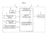
- the driving assistance device 1 is equipped with a camera 3L which captures a left-rearward of the vehicle 2 (hereinafter referred to as the left camera 3L), a navigation device 4, an indicator 5 for displaying the captured images of the left camera 3L and navigation information thereon, a turn signal sensor 6 which detects an operation state of a turn signal (not shown) as a direction indicator of the vehicle 2, a display-change operation switch 7 for performing changing of the display of the indicator 5, and an arithmetic processing unit 8 which performs control processing such as a display control of the indicator 5.
- a camera 3L which captures a left-rearward of the vehicle 2
- a navigation device 4 an indicator 5 for displaying the captured images of the left camera 3L and navigation information thereon
- a turn signal sensor 6 which detects an operation state of a turn signal (not shown) as
- the left camera 3L is configured from a CCD camera, a CMOS camera and the like. As is shown in Fig. 2 , the left camera 3L is mounted to a side on a left front side of the vehicle 2, for example to a left door mirror. The left camera 3L captures a left-rearward region ArL of the vehicle 2 (the self-vehicle 2), as is shown as a stippled region in Fig. 3 , and outputs the captured image data to the arithmetic processing unit 8.
- the element allotted with a reference number 3R with brackets is a camera (a right camera) to be equipped in a second embodiment to be explained later, and this camera 3R is not equipped in the present embodiment.
- the navigation device 4 is a heretofore known device with a navigation function such as a function of sequentially detecting a current position of the self-vehicle 2 using a GPS or an inertial navigation method, a function of matching the detected position of the self-vehicle 2 with a map data, and a function of setting a guidance path of the self-vehicle 2 to a destination, and the like.
- a navigation function such as a function of sequentially detecting a current position of the self-vehicle 2 using a GPS or an inertial navigation method, a function of matching the detected position of the self-vehicle 2 with a map data, and a function of setting a guidance path of the self-vehicle 2 to a destination, and the like.
- the navigation device 4 outputs to the arithmetic processing unit 8 a navigation information configured from the detected current position of the self-vehicle 2, the map data of surroundings of the self-vehicle 2, the guidance path information, and a detailed guide information of a specified detailed guide zone (a zone in a vicinity of an intersection, a branching point, a merging point and the like) of a road on which the self-vehicle 2 is traveling.
- the detailed guide information contains data of an enlarged guide view of the vicinity of the detailed guide zone, a scheduled course of the self-vehicle 2 at a specific point, and the like.
- the indicator 5 is a monitor configured from a liquid-crystal display and the like, and as is shown in Fig. 2 , is mounted at a position forward of a driving sheet in an interior of the vehicle 2, for example to a dashboard, so as to enable a driver to view the same.
- the turn signal sensor 6 detects ON/OFF of each of a left turn signal and a right turn signal of the vehicle 2, and outputs signals corresponding thereto to the arithmetic processing unit 8.
- Such turn signal sensor 6 may be a heretofore known sensor.
- the display-change operation switch 7 is a switch disposed in the vicinity of the indicator 5, and which is capable of being press-operated. When the press-operation is performed, the display-change operation switch 7 output a signal indicating the same to the arithmetic processing unit 8.
- the display-change operation switch 7 may be disposed on a handle, a turn signal lever and the like of the vehicle 2.
- the arithmetic processing unit 8 is an electronic circuit unit configured from a CPU, a RAM, a ROM, an interface circuit and the like, and is disposed at an appropriate location of the vehicle 2.
- the arithmetic processing unit 8 is equipped with, as a function realized by an implemented program or a hardware configuration and the like, a display control unit 9 which controls the display of the indicator 5, and a course change detecting unit 10 which detects existence or non-existence of a course change of the self-vehicle 2.
- the display control unit 9 and the course change detecting unit 10 respectively corresponds to a display control element and a course change detecting element of the present invention.
- the arithmetic processing unit 8 acquires, in a predetermined control processing cycle, the image data of the captured image (the captured image of the left-rearward of the vehicle 2) of the left camera 3L, the navigation information output from the navigation device 4, the output of the turn signal sensor 6, and the output of the display-change operation switch 7.
- the arithmetic processing unit 8 executes the processing of the course change detecting unit 10 and the display control unit 9 in each control processing cycle.
- the course change detecting unit 10 is input with the output of the turn signal sensor 6. Thereafter, on the basis of the output of the turn signal sensor 6 of the self-vehicle 2 which indicates the operating state (ON/OFF) of each of the left turn signal and the right turn signal, the course change detecting unit 10 detects existence or non-existence of the course change of the self-vehicle 2 (the course change which performs right or left turn, lane change, merge to a road scheduled to be traveled, branch (depart) from a traveling road, and the like). In this case, the course change detecting unit 10 detects the existence or non-existence of the course change of the self-vehicle 2, distinguishing the course change to right side and the course change to left side.
- the existence or non-existence of the course change of the self-vehicle 2 may be detected on the basis of time-series data and map data of the position of the self-vehicle 2 out of the navigation information of the navigation device 4, or a detected data of a steering angle of the self-vehicle 2.
- the course change may be detected even in a case where the course change of the vehicle is performed without operating the turn signal of the vehicle 2.
- the arithmetic processing unit 8 subsequently executes the processing of the display control unit 9.
- the display control unit 9 is input with the navigation information of the navigation device 4, the output of the display-change operation switch 7 (signal indicating the existence or non-existence of the press-operation of the switch 7), and the detection result of the course change detecting unit 10.
- the display control unit 9 determines the content to be displayed to the indicator 5, on the basis of these input data. Further, the display control unit 9 controls the display of the indicator 5, according to the determined display content.
- the display control is classified broadly into whether the current position of the self-vehicle 2 indicated by the navigation information is a position inside the detailed guide zone or a position outside the detailed guide zone.
- the display control unit 9 normally indicates an image NVa which includes an image of a map of the surrounding of the self-vehicle 2, which is indicated by the map data among the navigation information, and a mark indicating the current position of the self-vehicle 2, as a main constituent element thereof (hereinafter referred to as a normal navigation image NVa) to the indicator 5, as is shown in a view in a first (uppermost) row in Fig. 4 .
- a mark indicating the guiding path is displayed in the normal navigation image NVa.
- the display control unit 9 changes the display of the indicator 5 from the normal navigation image NVa.
- the display control unit 9 indicates a latest captured image of the left camera 3L (the left-rearward captured image of the vehicle 2, hereinafter referred to as a left-rearward image IML) which is imported to the arithmetic processing unit 8, instead of the normal navigation image NVa, to the indicator 5, as is shown in a view of a second row in Fig. 4 .
- a left-rearward image IML the left-rearward captured image of the vehicle 2
- the displayed image of the indicator 5 is changed from the normal navigation image NVa to the left-rearward image IML.
- a distance confirmation line Ld which gives an indication of a distance from the self-vehicle 2 is added to the left-rearward image IML.
- the display control unit 9 resumes the displayed image of the indicator 5 from the left-rearward image IML to the normal navigation image NVa, as is shown in a view of a third (lowermost) row in Fig. 4 .
- the display control unit 9 resumes the display of the indicator 5 from the left-rearward image IML to the normal navigation image NVa, in a same manner as described above.
- the display control unit 9 resumes the display of the indicator 5 from the left-rearward image IML to the normal navigation image NVa, in a same manner as described above.
- the display control unit 9 maintains the image displayed to the indicator 5 to the normal navigation image NVa, as is shown in the view of the first (the uppermost) row in Fig. 4 .
- the left-rearward image IML is not displayed to the indicator 5, and the displayed image of the indicator 5 is maintained to the normal navigation image NVa.
- the above-explained is the display control of the indicator 5, in a case where the current position of the self-vehicle 2 is the position outside the detailed guide zone.
- the display control unit 9 displays an image NVb of the detailed guide information (hereinafter referred to as a detailed guide image NVb), which includes an enlarged image of a substantial part of the detailed guide zone (the intersection, the merging point, the branching point and the like) as a main constitutional element thereof, to a right screen area of the indicator 5, and at the same time, displays the normal navigation image NVa or the left-rearward image IML to a left screen area of the indicator 5 as is shown in a view of a second row of FIG. 6 or in a view of a second row of FIG. 7 .
- a detailed guide image NVb which includes an enlarged image of a substantial part of the detailed guide zone (the intersection, the merging point, the branching point and the like) as a main constitutional element thereof, to a right screen area of the indicator 5, and at the same time, displays the normal navigation image NVa or the left-rearward image IML to a left screen area of the indicator 5 as is shown in a view of
- the normal navigation image NVa or the left-rearward image IML to be displayed to the left screen area of the indicator 5 is an image reduced from the image in a case where the current position of the self-vehicle 2 is the position outside the detailed guide zone (the image shown in Fig. 4 ).
- the detailed guide image NVb includes a mark indicating the guidance path of the self-vehicle 2 in the substantial part of the detailed guide zone.
- the image out of the normal navigation image NVa and the left-rearward image IML to be displayed to the left screen area of the indicator 5 is determined in response to the display of the indicator 5 immediately before the self-vehicle 2 enters the detailed guide zone.
- the display control unit 9 displays a reduced image of the normal navigation image NVa to the indicator 5 at the left side of the detailed guide image NVb, as is shown in Fig. 6 .
- the display control unit 9 displays a reduced image of the left-rearward image IML to the indicator 5 at the left side of the detailed guide image NVb, as is shown in Fig. 7 .
- the display control unit 9 performs the display control of the indicator 5, in a manner different in a case where the press-operation of the display-change operation switch 7 is performed, and in a case where the course change (the course change to the left side) of the vehicle 2 is detected by the course change detecting unit 10.
- the display control unit 9 changes the displayed image of the left screen area from the normal navigation image NVa to the left-rearward image IML, while maintaining the display of the detailed guide image IML to the right screen area of the indicator 5, as is shown in a left view of a third row in Fig. 6 .
- the display control unit 9 resumes the displayed image of the left screen area from the left-rearward image IML to the normal navigation image NVa, while maintaining the display of the detailed guide image NVb to the right screen area of the indicator 5, as is shown in a view of a fourth row in Fig. 6 .
- the display state of the indicator 5 is retained at a state of the view of the second row in Fig. 6 (a state of indicating the normal navigation image NVa and the detailed guide image NVb).
- the display control unit 9 displays only the left-rearward image IML to the indicator 5, as is shown in a right view of the third row in Fig. 6 , without performing the display of the detailed guide image NVb or the normal navigation image NVa, in either case of a case where the normal navigation image NVa and the detailed guide image NVb are displayed to the indicator 5 and a case where the left-rearward image IML and the detailed guide image NVb are displayed to the indicator 5.
- the display control unit 9 resumes the display state of the indicator 5 to the display state immediately after the current position of the self-vehicle 2 is changed from the position outside the detailed guide zone to the position inside the detailed guide zone (in this case, a state of indicating the normal navigation image NVa and the detailed guide image NVb).
- the displayed image in the left screen area of the indicator 5 may be changed from the normal navigation image NVa to the left-rearward image IML, while maintaining the display of the detailed guide image NVb to the right screen area.
- the display control unit 9 retains the current display state (a state of displaying the left-rearward image IML and the detailed guide image NVb), without changing the display state of the indicator 5, including a case where the detection of the course change is dissolved (in a case where the course change is finished), as is shown in a left view of a third row and a view of a fourth row in Fig. 7 .
- the display control unit 9 displays only the left-rearward image IML to the indicator 5, without performing the display of the detailed guide image NVb or the normal navigation image NVa, as is shown in a right view of the third row in Fig. 7 .
- the display control unit 9 resumes the display state of the indicator 5 to the display state immediately after the current position of the self-vehicle 2 is changed from the position outside the detailed guide zone to the position inside the detailed guide zone (in this case, the state of displaying the left-rearward image IML and the detailed guide image NVb).
- the normal navigation image NVa and the detailed guide image NVb may be displayed to the indicator 5, similarly to the case shown in the view of the second row in Fig. 6 .
- the display control unit 9 dissolves the display of the detailed guide image NVb, as is shown in a view of a fifth (lowermost) row in Fig. 6 or Fig. 7 . Thereafter, the display control unit 9 displays an enlarged image of the normal navigation image NVa or the left-rearward image IML, which had been displayed to the left screen area of the indicator 5 immediately before (the normal navigation image NVa or the left-rearward image IML shown in Fig. 4 ) to the indicator 5.
- the above is the display control of the indicator 5, in a case where the current position of the self-vehicle 2 is changed from the position outside the detailed guide zone to the position inside the detailed guide zone.
- the detailed guide image NVb which has high importance to the driver as the information in the detailed guide zone, is displayed continuously to the indicator 5, unless the driver intentionally performs the press-operation of the display-change operation switch 7.
- the display of the detailed guide image NVb will not be automatically deleted without explicit request from the driver. Therefore, in a situation where the vehicle 2 is traveling in the detailed guide zone, the driver is capable of confirming the detailed guide image having high importance continuously and without any problem.
- the driver press-operates the display-change operation switch 7, it becomes possible to display only the left-rearward image IML to the indicator 5, without displaying the detailed guide image NVb, according to need. Therefore, the driver may display the left-rearward image IML to the indicator 5, during course change to the left side of the self-vehicle 2 and the like, according to need. By doing so, the driver may actively confirm the left-rearward state of the self-vehicle 2.
- the display control unit 9 displays the displayed image immediately before the change (the normal navigation image NVa or the left-rearward image IML) to the indicator 5, together with the detailed guide image NVb Therefore, the displayed image that the driver was observing immediately before the change will not be automatically deleted from the indicator 5 immediately after the change, without the request from the driver.
- the present embodiment it becomes possible to display the navigation information constituted from the normal navigation image NVa and the detailed guide image NVb, and the display of the captured image of rearward (in the present embodiment, left-rearward) of the vehicle 2, to the indicator 5, in a manner appropriately reflecting the request or the necessity of the driver.
- FIG. 1 a second embodiment of the present invention will be explained with reference to Fig. 1 and Figs. 8 through 11 .
- the present embodiment differs from the first embodiment in a part of the configuration and processing, so that the explanation will be mainly given on the differences.
- the detailed explanation of the same configuration and processing as the first embodiment will be omitted.
- a driving assistance device 21 of the present embodiment is equipped with, similar to the first embodiment, the left camera 3L, the navigation device 4, the indicator 5, the turn signal sensor 6, the display-change operation switch 7, and the arithmetic processing unit 8, and in addition thereto, a camera 3R (hereinafter referred to as a right camera 3R) which captures a right rearward of the vehicle 2.
- a camera 3R hereinafter referred to as a right camera 3R
- the right camera 3R is, similar to the left camera 3L, configured from a CCD camera, a CMOS camera and the like. As is indicated by a reference number with brackets in Fig. 2 , the right camera 3R is mounted to a side on a right front side of the vehicle 2, for example to a right door mirror. As is shown in Fig. 9 , the right camera 3R captures a right-rearward region ArR of the vehicle 2 (the self-vehicle 2), and outputs the captured image data to the arithmetic processing unit 8.
- the arithmetic processing unit 8 is equipped with, as a function thereof, the display control unit 9 and the course change detecting unit 10.
- the display control unit 9 the course change detecting unit 10.
- a part of the manner of the display control of the indicator 5 by the display control unit 9 differs from the first embodiment.
- the display control unit 9 is input with, similar to the first embodiment, the navigation information of the navigation device 4, the output of the display-change operation switch 7, and the detection result of the course change detecting unit 10.
- the display control unit 9 determines the content to be displayed on the indicator 5, on the basis of these input data. Further, the display control unit 9 controls the display of the indicator 5, according to the determined display content.
- the display control unit 9 in normal times displays, similarly to the first embodiment, the normal navigation image NVa to the indicator 5 (refer to a view in a first (uppermost) row in Fig. 10 ).
- the display control unit 9 changes the displayed image of the indicator 5 from the normal navigation image NVa to either one or both of the captured images of the left camera 3L and the right camera 3R, on the basis of the press-operation of the display-change operation switch 7, or the detection of the course change of the self-vehicle 2 by the course change detecting unit 10.
- the display control unit 9 displays the left-rearward image IML which is the latest captured image by the left camera 3L, and a right-rearward image IMR which is the latest captured image by the right camera 3R, as is shown in a central view of a second row in Fig. 10 .
- the left-rearward image IML is displayed to the left screen area of the indicator 5
- the right-rearward image IMR is displayed to the right screen area of the indicator 5.
- the distance confirmation line Ld which gives an indication of the distance from the self-vehicle 2 is added to both of the left-rearward image IML and the right-rearward image IMR.
- the display control unit 9 resumes the displayed image of the indicator 5 to the normal navigation image NVa, as is shown in a view of a third (lowermost) row in Fig. 10 .
- the display control unit 9 displays the left-rearward image IML (including the distance confirmation line Ld), as is shown in a left view of the second row in Fig. 10 .
- the display control unit 9 displays the right-rearward image IMR (including the distance confirmation line Ld), as is shown in a right view of second row inFig. 10.
- the display control unit 9 resumes the displayed image of the indicator 5 to the normal navigation image NVa, as is shown in the view of the third (lowermost) row in Fig. 10 .
- the display control unit 9 resumes the displayed image of the indicator 5 to the normal navigation image NVa. Therefore, at a state in which either one or both of the left-rearward image IML and the right-rearward image IMR are displayed to the indicator 5, the displayed image of the indicator 5 is changed to the normal navigation image NVa in both cases, in a case where the display-change operation switch 7 is press-operated.
- the display state of the indicator 5 is switched to the display state of the left-rearward image IML only, and the display state of the right-rearward image IMR only, respectively.
- the course change to the right side is detected by the course change detecting unit 10 at a state in which the left-rearward image IML is displayed to the indicator 5
- the displayed image of the indicator 5 is changed from the left-rearward image IML to the right-rearward image IMR.
- the course change to the left side is detected by the course change detecting unit 10 at a state in which the right-rearward image IMR is displayed to the indicator 5
- the displayed image of the indicator 5 is changed from the right-rearward image IML to the left-rearward image IML.
- the display control of the indicator 5 by the display control unit 9 is basically performed in a similar manner as in the first embodiment.
- the display control unit 9 displays the normal navigation image NVa and the detailed guide image NVb to the indicator 5 after the change of the current position of the self-vehicle 2, similar to the case shown in the view of the second row in Fig. 6.
- the display control unit 9 displays the captured image already displayed to the indicator 5 (either one or both of IML and IMR) and the detailed guide image NVb to the indicator 5, after the change of the current position of the self-vehicle 2.
- the reduced captured image and the detailed guide image NVb are displayed at either one of the arrangement patterns shown in Figs. 11A through C , according to which captured image was displayed to the indicator 5 before the change of the current position of the self-vehicle 2.
- the display control unit 9 displays the reduced left-rearward image IML and the detailed guide image NVb to the left screen area and the right screen area of the indicator 5, respectively, as is shown in Fig. 11A .
- the display control unit 9 displays the reduced right-rearward image IMR and the detailed guide image NVb to the right screen area and the left screen area of the indicator 5, respectively, as is shown in Fig. 11B .
- the display control unit 9 displays the reduced left-rearward image IML, the detailed guide image NVb, and the reduced right-rearward image IMR, to the left screen area, the center screen area, and the right screen area of the indicator 5, respectively, as is shown in Fig. 11C .
- the display of the indicator 5 is controlled to the display state shown in Fig. 11A (a state of displaying the left-rearward image IML and the detailed guide image NVb) and the display state shown in Fig. 11B (a state of displaying the right-rearward image IMR and the detailed guide image NVb), respectively, in either of the display state of the state where the normal navigation image NVa and the detailed guide image NVb are displayed to the indicator 5 (state shown in the view of the second row in Fig. 6 ), or a state where the captured image (either one or both of IML and IMR) and the detailed guide image NVb are displayed to the indicator 5 (state shown in either one of Figs. 11A through C ).
- the display of the indicator 5 is resumed to the display state immediately after the current position of the self-vehicle 2 is changed from the position outside the detailed guide zone to the position inside the detailed guide zone.
- the display of the detailed guide image NVb is not automatically deleted in resonse to the detection of the course change of the self-vehicle 2 by the course change detecting unit 10.
- the display control unit 9 displays either one or both of the left-rearward image IML and the right-rearward image IMR, without performing display of the detailed guide image NVb or the normal navigation image NVa.
- the display control unit 9 displays both of the left-rearward image IML and the right-rearward image IMR to the indicator 5, in the manner of the central view of the second row in Fig. 10 .
- the display control unit 9 displays only the left-rearward image IML to the indicator 5, in the manner shown in the left view of the second row in Fig. 10 .
- the display control unit 9 displays only the right-rearward image IMR to the indicator 5, in the manner shown in the right view of the second row in Fig. 10 .
- the display control unit 9 resumes the display state of the indicator 5 to the display state immediately after the current position of the self-vehicle 2 is changed from the position outside the detailed guide zone to the position inside the detailed guide zone (in this case, the state of displaying the left-rearward image IML and the detailed guide image NVb), similarly to the case of the first embodiment.
- the display control unit 9 dissolves the displaying of the detailed guide image NVb. Thereafter, the display control unit 9 displays the enlarged view of the image displayed immediately before together with the detailed guide image NVb (the normal navigation image NVa, or either one or both of the left-rearward image IML and the right-rearward image IMR) to the indicator 5, in the manner shown in Fig. 10 .
- the present embodiment is the same as the above-explained first embodiment, except for matters explained above.
- the detailed guide image NVb which has high necessity to the driver as the information in the detailed guide zone, is displayed continuously to the indicator 5, unless the driver intentionally performs the press-operation of the display-change operation switch 7, similarly to the first embodiment.
- the display of the detailed guide image NVb will not be automatically deleted without explicit request from the driver. Therefore, in a situation where the vehicle 2 is traveling in the detailed guide zone, the driver is capable of confirming the detailed guide image having high importance continuously and without any problem.
- the driver may display either one or both of the left-rearward image IML and the right-rearward image IMR to the indicator 5, during course change of the self-vehicle 2 and the like, according to need. By doing so, the driver may aggressively confirm the left or the right-rearward state of the self-vehicle 2.
- the display control unit 9 displays the displayed image immediately before the change (the normal navigation image NVa, or either one or both of the left-rearward image IML and the right-rearward image IMR), to the indicator 5, together with the detailed guide image NVb. Therefore, the displayed image that the driver was observing immediately before the change will not be automatically deleted from the indicator 5 immediately after the change, without the request from the driver, similarly to the first embodiment.
- the present embodiment it becomes possible to display the navigation information configured from the normal navigation image NVa and the detailed guide image NVb, and the display of the captured image of the rearward of the vehicle 2, to the indicator 5, in a manner appropriately reflecting the request or the necessity of the driver, similarly to the first embodiment.
- either one or both of the left-rearward image IML and the right-rearward image IMR are displayed to the indicator 5, such that the left-rearward image IML, which is the captured image by the left camera 3L, is positioned to the left side with respect to the detailed guide image NVb (on the same side as the left camera 3L in the right-left direction), and the right-rearward image IMR which is the captured image by the right camera 3R is positioned to the right side with respect to the detailed guide image NVb (on the same side as the right camera 3R in the right-left direction).
- the driver may accurately recognize the situation of the left rearward or the right rearward of the self-vehicle 2 with the left-rearward image IML or the right-rearward image IMR, respectively.
- the vehicle 2 is a right-handled vehicle.
- the vehicle 2 may be a left-handled vehicle.
- the vehicle 2 is a left-handled vehicle
- only the right camera 3R out of the left camera 3L and the right camera 3R may be mounted to the vehicle 2.
- the right-rearward image IMR and the detailed guide image NVb may be displayed to the indicator 5 in the manner shown in, for example, Fig. 11B , but also the right-rearward image IMR may be displayed to the left screen area of the detailed guide image NVb
- the right-rearward image IMR is not displayed to the indicator 5 when detecting the course change to the left side, and the right-rearward image IMR is displayed to the indicator 5 when detecting the course change to the right side.
Applications Claiming Priority (2)
| Application Number | Priority Date | Filing Date | Title |
|---|---|---|---|
| JP2011161949 | 2011-07-25 | ||
| PCT/JP2012/064262 WO2013015021A1 (ja) | 2011-07-25 | 2012-06-01 | 車両の運転支援装置 |
Publications (2)
| Publication Number | Publication Date |
|---|---|
| EP2722834A1 true EP2722834A1 (de) | 2014-04-23 |
| EP2722834A4 EP2722834A4 (de) | 2015-01-21 |
Family
ID=47600881
Family Applications (1)
| Application Number | Title | Priority Date | Filing Date |
|---|---|---|---|
| EP12817795.3A Withdrawn EP2722834A4 (de) | 2011-07-25 | 2012-06-01 | Fahrhilfevorrichtung für ein fahrzeug |
Country Status (5)
| Country | Link |
|---|---|
| US (1) | US20140132753A1 (de) |
| EP (1) | EP2722834A4 (de) |
| JP (1) | JPWO2013015021A1 (de) |
| CN (1) | CN103688299A (de) |
| WO (1) | WO2013015021A1 (de) |
Cited By (2)
| Publication number | Priority date | Publication date | Assignee | Title |
|---|---|---|---|---|
| CN104464317A (zh) * | 2014-12-03 | 2015-03-25 | 武汉理工大学 | 高速公路入口匝道合流区引导控制系统和方法 |
| GB2559828A (en) * | 2017-10-12 | 2018-08-22 | Andrew Ransom Steven | Vehicle camera system |
Families Citing this family (12)
| Publication number | Priority date | Publication date | Assignee | Title |
|---|---|---|---|---|
| KR20150073269A (ko) * | 2013-12-20 | 2015-07-01 | 현대자동차주식회사 | 차량용 클러스터 장치 |
| JP6248836B2 (ja) * | 2014-07-10 | 2017-12-20 | 株式会社デンソー | 運転支援装置 |
| JP6337743B2 (ja) * | 2014-11-04 | 2018-06-06 | トヨタ車体株式会社 | 車両の情報表示システム |
| US9983591B2 (en) * | 2015-11-05 | 2018-05-29 | Ford Global Technologies, Llc | Autonomous driving at intersections based on perception data |
| JP2018116516A (ja) * | 2017-01-19 | 2018-07-26 | トヨタ自動車株式会社 | 車両の注意喚起装置 |
| US10234858B2 (en) * | 2017-04-18 | 2019-03-19 | Aptiv Technologies Limited | Automated vehicle control system |
| EP3392801A1 (de) * | 2017-04-21 | 2018-10-24 | Harman International Industries, Incorporated | Systeme und verfahren zur fahrerassistenz |
| CN108229386B (zh) * | 2017-12-29 | 2021-12-14 | 百度在线网络技术(北京)有限公司 | 用于检测车道线的方法、装置和介质 |
| JP7128096B2 (ja) * | 2018-11-26 | 2022-08-30 | 本田技研工業株式会社 | 映像表示装置 |
| KR20200071854A (ko) * | 2018-12-04 | 2020-06-22 | 현대자동차주식회사 | 차량의 멀티미디어 제어 장치 및 방법 |
| WO2022044112A1 (ja) * | 2020-08-25 | 2022-03-03 | 日産自動車株式会社 | 車両制御方法及び車両制御装置 |
| CN112216111A (zh) * | 2020-10-16 | 2021-01-12 | 重庆伟登交通工程设计咨询有限公司 | 一种基于微波雷达和视频图像的车速车距预警系统及方法 |
Citations (5)
| Publication number | Priority date | Publication date | Assignee | Title |
|---|---|---|---|---|
| WO2006006689A1 (en) * | 2004-07-12 | 2006-01-19 | Sharp Kabushiki Kaisha | Display system, vehicle, display method, display program and storage medium thereof |
| US20070233370A1 (en) * | 2006-03-30 | 2007-10-04 | Denso Corporation | Navigation system |
| US20100066518A1 (en) * | 2008-09-16 | 2010-03-18 | Honda Motor Co., Ltd. | Vehicle surroundings monitoring apparatus |
| WO2010080610A1 (en) * | 2008-12-19 | 2010-07-15 | Delphi Technologies, Inc. | Electronic side view display system |
| JP2010198428A (ja) * | 2009-02-26 | 2010-09-09 | Alpine Electronics Inc | 車載システム |
Family Cites Families (8)
| Publication number | Priority date | Publication date | Assignee | Title |
|---|---|---|---|---|
| JPH1047979A (ja) * | 1996-08-05 | 1998-02-20 | Toyota Motor Corp | 車両用ナビゲーション装置および車両用ナビゲーション装置の表示制御方法 |
| JP2002117496A (ja) * | 2000-10-12 | 2002-04-19 | Matsushita Electric Ind Co Ltd | 車載後方確認支援装置と車載ナビゲーション装置 |
| JP4300353B2 (ja) * | 2003-11-06 | 2009-07-22 | 日産自動車株式会社 | 後側方映像提供装置 |
| JP2006051850A (ja) | 2004-08-10 | 2006-02-23 | Matsushita Electric Ind Co Ltd | 運転支援装置及び運転支援方法 |
| JP5117003B2 (ja) * | 2006-07-11 | 2013-01-09 | 本田技研工業株式会社 | 運転支援装置 |
| JP4948944B2 (ja) | 2006-09-06 | 2012-06-06 | アルパイン株式会社 | ナビゲーション装置および交差点案内図の描画方法 |
| JP5027759B2 (ja) * | 2008-08-19 | 2012-09-19 | 本田技研工業株式会社 | 車両の視覚支援装置 |
| JP2011003117A (ja) * | 2009-06-22 | 2011-01-06 | Central Motor Co Ltd | 後方視認支援システム |
-
2012
- 2012-06-01 CN CN201280035330.3A patent/CN103688299A/zh active Pending
- 2012-06-01 WO PCT/JP2012/064262 patent/WO2013015021A1/ja active Application Filing
- 2012-06-01 EP EP12817795.3A patent/EP2722834A4/de not_active Withdrawn
- 2012-06-01 JP JP2013525613A patent/JPWO2013015021A1/ja active Pending
- 2012-06-01 US US14/131,478 patent/US20140132753A1/en not_active Abandoned
Patent Citations (5)
| Publication number | Priority date | Publication date | Assignee | Title |
|---|---|---|---|---|
| WO2006006689A1 (en) * | 2004-07-12 | 2006-01-19 | Sharp Kabushiki Kaisha | Display system, vehicle, display method, display program and storage medium thereof |
| US20070233370A1 (en) * | 2006-03-30 | 2007-10-04 | Denso Corporation | Navigation system |
| US20100066518A1 (en) * | 2008-09-16 | 2010-03-18 | Honda Motor Co., Ltd. | Vehicle surroundings monitoring apparatus |
| WO2010080610A1 (en) * | 2008-12-19 | 2010-07-15 | Delphi Technologies, Inc. | Electronic side view display system |
| JP2010198428A (ja) * | 2009-02-26 | 2010-09-09 | Alpine Electronics Inc | 車載システム |
Non-Patent Citations (1)
| Title |
|---|
| See also references of WO2013015021A1 * |
Cited By (7)
| Publication number | Priority date | Publication date | Assignee | Title |
|---|---|---|---|---|
| CN104464317A (zh) * | 2014-12-03 | 2015-03-25 | 武汉理工大学 | 高速公路入口匝道合流区引导控制系统和方法 |
| CN104464317B (zh) * | 2014-12-03 | 2016-05-11 | 武汉理工大学 | 高速公路入口匝道合流区引导控制系统和方法 |
| GB2559828A (en) * | 2017-10-12 | 2018-08-22 | Andrew Ransom Steven | Vehicle camera system |
| GB2559828B (en) * | 2017-10-12 | 2019-01-30 | Andrew Ransom Steven | Vehicle camera system |
| GB2567510A (en) * | 2017-10-12 | 2019-04-17 | Andrew Ransom Steven | Vehicle camera system |
| WO2019073208A1 (en) * | 2017-10-12 | 2019-04-18 | Steven Andrew Ransom | VEHICLE CAMERA SYSTEM |
| GB2567510B (en) * | 2017-10-12 | 2020-01-15 | Andrew Ransom Steven | Rear view camera system |
Also Published As
| Publication number | Publication date |
|---|---|
| WO2013015021A1 (ja) | 2013-01-31 |
| JPWO2013015021A1 (ja) | 2015-02-23 |
| EP2722834A4 (de) | 2015-01-21 |
| CN103688299A (zh) | 2014-03-26 |
| US20140132753A1 (en) | 2014-05-15 |
Similar Documents
| Publication | Publication Date | Title |
|---|---|---|
| EP2722834A1 (de) | Fahrhilfevorrichtung für ein fahrzeug | |
| EP3437949B1 (de) | Anzeigevorrichtung | |
| EP3650285B1 (de) | Parkhilfeverfahren und parkhilfevorrichtung | |
| US10163016B2 (en) | Parking space detection method and device | |
| JP4510019B2 (ja) | 車両用表示装置、車両、表示方法、画像表示プログラム、および記録媒体 | |
| JP6209232B2 (ja) | 車線変更支援装置 | |
| CN108351958B (zh) | 停车位的框线的检测方法及装置 | |
| JP4853712B2 (ja) | 駐車支援装置 | |
| US20180315312A1 (en) | Parking Support Method and Parking Support Device | |
| EP3340616B1 (de) | Fahrzeugumfeldüberwachungsvorrichtung | |
| JP2006284458A (ja) | 運転支援情報表示システム | |
| CN110920521A (zh) | 显示系统、显示方法及存储介质 | |
| JP2004334808A (ja) | 起動判断装置 | |
| CN112977061A (zh) | 车辆用显示装置、记录程序的记录介质及车辆用显示方法 | |
| CN114340966A (zh) | 停车辅助方法及停车辅助装置 | |
| EP3805065A1 (de) | Zustandsbestimmungsvorrichtung, fahrunterstützungsvorrichtung, zustandsbestimmungsverfahren und fahrunterstützungsverfahren | |
| JP5056684B2 (ja) | ナビゲーション装置、交通状況案内方法及び交通状況案内プログラム | |
| JP2019191722A (ja) | 車線変更支援装置 | |
| JP2010146079A (ja) | 車両用運転支援装置 | |
| JP2005067403A (ja) | 車載運転補助装置 | |
| JP2016197312A (ja) | 運転支援表示装置 | |
| JP2012081838A (ja) | 駐車支援装置 | |
| JP2010224610A (ja) | 運転支援装置、運転支援方法および運転支援プログラム | |
| WO2021132306A1 (ja) | 表示制御装置、表示装置、表示制御方法及びプログラム | |
| JP2009149306A (ja) | 車両用表示装置 |
Legal Events
| Date | Code | Title | Description |
|---|---|---|---|
| PUAI | Public reference made under article 153(3) epc to a published international application that has entered the european phase |
Free format text: ORIGINAL CODE: 0009012 |
|
| 17P | Request for examination filed |
Effective date: 20140115 |
|
| AK | Designated contracting states |
Kind code of ref document: A1 Designated state(s): AL AT BE BG CH CY CZ DE DK EE ES FI FR GB GR HR HU IE IS IT LI LT LU LV MC MK MT NL NO PL PT RO RS SE SI SK SM TR |
|
| DAX | Request for extension of the european patent (deleted) | ||
| A4 | Supplementary search report drawn up and despatched |
Effective date: 20141219 |
|
| RIC1 | Information provided on ipc code assigned before grant |
Ipc: H04N 7/18 20060101ALI20141215BHEP Ipc: B60R 11/02 20060101ALI20141215BHEP Ipc: B60R 11/04 20060101ALI20141215BHEP Ipc: B60R 1/00 20060101ALI20141215BHEP Ipc: G08G 1/16 20060101AFI20141215BHEP Ipc: G01C 21/36 20060101ALI20141215BHEP |
|
| STAA | Information on the status of an ep patent application or granted ep patent |
Free format text: STATUS: THE APPLICATION IS DEEMED TO BE WITHDRAWN |
|
| 18D | Application deemed to be withdrawn |
Effective date: 20150723 |