EP2722112B2 - Dispositif et procédé destinés au traitement continu d'une bande métallique - Google Patents
Dispositif et procédé destinés au traitement continu d'une bande métallique Download PDFInfo
- Publication number
- EP2722112B2 EP2722112B2 EP13183368.3A EP13183368A EP2722112B2 EP 2722112 B2 EP2722112 B2 EP 2722112B2 EP 13183368 A EP13183368 A EP 13183368A EP 2722112 B2 EP2722112 B2 EP 2722112B2
- Authority
- EP
- European Patent Office
- Prior art keywords
- strip
- cooling line
- adjustment device
- position adjustment
- line section
- Prior art date
- Legal status (The legal status is an assumption and is not a legal conclusion. Google has not performed a legal analysis and makes no representation as to the accuracy of the status listed.)
- Active
Links
Images
Classifications
-
- C—CHEMISTRY; METALLURGY
- C21—METALLURGY OF IRON
- C21D—MODIFYING THE PHYSICAL STRUCTURE OF FERROUS METALS; GENERAL DEVICES FOR HEAT TREATMENT OF FERROUS OR NON-FERROUS METALS OR ALLOYS; MAKING METAL MALLEABLE, e.g. BY DECARBURISATION OR TEMPERING
- C21D9/00—Heat treatment, e.g. annealing, hardening, quenching or tempering, adapted for particular articles; Furnaces therefor
- C21D9/52—Heat treatment, e.g. annealing, hardening, quenching or tempering, adapted for particular articles; Furnaces therefor for wires; for strips ; for rods of unlimited length
- C21D9/54—Furnaces for treating strips or wire
- C21D9/56—Continuous furnaces for strip or wire
- C21D9/573—Continuous furnaces for strip or wire with cooling
-
- C—CHEMISTRY; METALLURGY
- C21—METALLURGY OF IRON
- C21D—MODIFYING THE PHYSICAL STRUCTURE OF FERROUS METALS; GENERAL DEVICES FOR HEAT TREATMENT OF FERROUS OR NON-FERROUS METALS OR ALLOYS; MAKING METAL MALLEABLE, e.g. BY DECARBURISATION OR TEMPERING
- C21D9/00—Heat treatment, e.g. annealing, hardening, quenching or tempering, adapted for particular articles; Furnaces therefor
- C21D9/52—Heat treatment, e.g. annealing, hardening, quenching or tempering, adapted for particular articles; Furnaces therefor for wires; for strips ; for rods of unlimited length
- C21D9/54—Furnaces for treating strips or wire
-
- C—CHEMISTRY; METALLURGY
- C21—METALLURGY OF IRON
- C21D—MODIFYING THE PHYSICAL STRUCTURE OF FERROUS METALS; GENERAL DEVICES FOR HEAT TREATMENT OF FERROUS OR NON-FERROUS METALS OR ALLOYS; MAKING METAL MALLEABLE, e.g. BY DECARBURISATION OR TEMPERING
- C21D9/00—Heat treatment, e.g. annealing, hardening, quenching or tempering, adapted for particular articles; Furnaces therefor
- C21D9/46—Heat treatment, e.g. annealing, hardening, quenching or tempering, adapted for particular articles; Furnaces therefor for sheet metals
-
- C—CHEMISTRY; METALLURGY
- C21—METALLURGY OF IRON
- C21D—MODIFYING THE PHYSICAL STRUCTURE OF FERROUS METALS; GENERAL DEVICES FOR HEAT TREATMENT OF FERROUS OR NON-FERROUS METALS OR ALLOYS; MAKING METAL MALLEABLE, e.g. BY DECARBURISATION OR TEMPERING
- C21D9/00—Heat treatment, e.g. annealing, hardening, quenching or tempering, adapted for particular articles; Furnaces therefor
- C21D9/52—Heat treatment, e.g. annealing, hardening, quenching or tempering, adapted for particular articles; Furnaces therefor for wires; for strips ; for rods of unlimited length
- C21D9/54—Furnaces for treating strips or wire
- C21D9/56—Continuous furnaces for strip or wire
- C21D9/562—Details
- C21D9/563—Rolls; Drums; Roll arrangements
-
- C—CHEMISTRY; METALLURGY
- C21—METALLURGY OF IRON
- C21D—MODIFYING THE PHYSICAL STRUCTURE OF FERROUS METALS; GENERAL DEVICES FOR HEAT TREATMENT OF FERROUS OR NON-FERROUS METALS OR ALLOYS; MAKING METAL MALLEABLE, e.g. BY DECARBURISATION OR TEMPERING
- C21D9/00—Heat treatment, e.g. annealing, hardening, quenching or tempering, adapted for particular articles; Furnaces therefor
- C21D9/52—Heat treatment, e.g. annealing, hardening, quenching or tempering, adapted for particular articles; Furnaces therefor for wires; for strips ; for rods of unlimited length
- C21D9/54—Furnaces for treating strips or wire
- C21D9/56—Continuous furnaces for strip or wire
- C21D9/562—Details
- C21D9/564—Tension control
-
- C—CHEMISTRY; METALLURGY
- C21—METALLURGY OF IRON
- C21D—MODIFYING THE PHYSICAL STRUCTURE OF FERROUS METALS; GENERAL DEVICES FOR HEAT TREATMENT OF FERROUS OR NON-FERROUS METALS OR ALLOYS; MAKING METAL MALLEABLE, e.g. BY DECARBURISATION OR TEMPERING
- C21D9/00—Heat treatment, e.g. annealing, hardening, quenching or tempering, adapted for particular articles; Furnaces therefor
- C21D9/52—Heat treatment, e.g. annealing, hardening, quenching or tempering, adapted for particular articles; Furnaces therefor for wires; for strips ; for rods of unlimited length
- C21D9/54—Furnaces for treating strips or wire
- C21D9/56—Continuous furnaces for strip or wire
- C21D9/63—Continuous furnaces for strip or wire the strip being supported by a cushion of gas
-
- C—CHEMISTRY; METALLURGY
- C22—METALLURGY; FERROUS OR NON-FERROUS ALLOYS; TREATMENT OF ALLOYS OR NON-FERROUS METALS
- C22F—CHANGING THE PHYSICAL STRUCTURE OF NON-FERROUS METALS AND NON-FERROUS ALLOYS
- C22F1/00—Changing the physical structure of non-ferrous metals or alloys by heat treatment or by hot or cold working
- C22F1/04—Changing the physical structure of non-ferrous metals or alloys by heat treatment or by hot or cold working of aluminium or alloys based thereon
Definitions
- the invention relates to a device for the continuous treatment of a metal strip, in particular a metal strip made of aluminum (or an aluminum alloy) or of non-ferrous metal (or a non-ferrous metal alloy), with at least one tempering device designed as a strip floatation furnace through which the metal strip is passed in a suspended state, and with a strip travel control device with which the position of the metal strip in the strip travel plane and transversely to the strip travel direction can be controlled or regulated.
- the strip floatation furnace has at least one heating section on the inlet side and one cooling section on the outlet side.
- the metal strip preferably has a thickness of 0.1 mm to 6 mm.
- the DE 103 26 071 discloses a device for the continuous treatment of a metal strip, comprising at least one tempering device through which the metal strip is guided in a suspended manner and comprising a strip position control device with which the position of the metal strip in the strip travel plane and transversely to the strip travel direction can be controlled or regulated, wherein the tempering device has at least one heating section on the inlet side and one cooling section on the outlet side.
- Such a device of the type described above for the continuous treatment of a metal strip with a tempering device or with a strip floatation furnace can, for example, be an annealing line or continuous annealing line in which the metal strip undergoes heat treatment for metallurgical reasons, e.g., to achieve specific strength and deformation properties.
- the device can also be a strip coating system or a strip coating line in which the heat treatment of the metal strip is not carried out in the sense of annealing, but rather to dry a coating on the strip, so that the furnace is then designed as a continuous dryer.
- the metal strip is preferably aluminum or non-ferrous metal strip in a thickness range of 0.1 mm to 6 mm.
- the metal strip Since the metal strip is heated to temperatures close to its melting point, for example, in annealing lines, it is generally necessary to set a relatively low strip tension within the tempering device to avoid strip breakage. To this end, the strip tension is reduced, for example, on the inlet side in a set of tension rollers and, after cooling, is increased again on the outlet side in another set of tension rollers.
- the specific strip tension In the tempering device (strip floatation furnace), the specific strip tension is, for example, 0.5 to 1 MPa. Since the strip can "run off" in the furnace, especially at low strip tension, e.g., due to possible strip sabering, it is necessary to position the strip appropriately using a strip position control device, preferably to the center of the strip.
- Such a strip travel control device typically has at least one control roller and suitable position measuring devices, e.g., strip edge detection.
- the strip tracking control device is located behind the tempering device, i.e., after the cooling section.
- the control roller is usually designed as a so-called PI strip center control, i.e., with a proportional P and an integral I component. The I component feeds back into the furnace section and prevents the strip from wandering excessively in the furnace.
- the control roller is usually mounted on a movable base frame. This rotates the roller around an imaginary pivot point or an imaginary axis of rotation located in the furnace section and perpendicular to the strip travel plane.
- the DE 103 26 071 A1 A system is known in which a deflection device is arranged on the outlet side behind a strip floatation furnace, below which a water cup acts as a fluid seal.
- the deflection device can also simultaneously serve as a strip center control, with the strip position being detected by sensors arranged above and below the strip, and the movement of the strip center control for returning a strip running from the center position is carried out by means of a cylinder.
- the invention is based on the object of creating a device for the continuous treatment of a metal strip of the type described above, which is characterized by improved strip position control and which guarantees perfect strip running, especially in long furnace sections.
- the invention teaches a device having the features of claim 1.
- the cooling section is divided into at least a first cooling section and a subsequent, spaced-apart second cooling section, wherein the strip position control device is arranged between the first cooling section and the second cooling section.
- the strip position control device is therefore no longer arranged on the output side behind the tempering device and consequently no longer after the last cooling zone, but is integrated into the cooling section by dividing the latter into two cooling section sections.
- the strip In a first section, the strip is cooled to such an extent that it can easily pass the strip position control device.
- the strip position control device is therefore located downstream of the first cooling section.
- the strip then passes through the second cooling section and consequently the second part of the cooling zones, so that the strip is subsequently cooled to the desired final temperature.
- the strip then passes through the second cooling section and consequently the second part of the cooling zones, so that the strip is subsequently cooled to the desired final temperature.
- the strip position control device itself can be designed in a conventional manner, thus allowing the use of conventional solutions. According to the invention, the specific positioning of the strip guide device within the furnace section or within the cooling section is important.
- the strip position control device for strip position control can comprise a conventional, adjustable deflection roller, e.g., a 90° deflection roller, or be designed as such.
- a suitable (high-)temperature-resistant coating since the strip temperature between the first cooling section and the second cooling section is preferably 100°C to 200°C, particularly preferably 120°C to 150°C.
- a 90° control roller another known type of strip center control can also be used, e.g., using a multi-roller control device, e.g., a three-roller control device or a control driver (e.g., as a pair of rollers). Suitable coatings are also preferably provided in this case.
- the strip position control or strip center control is implemented in a basically known manner as PI control.
- the control roller or multi-roller arrangement is therefore seated on a movable base frame in a basically known manner. This rotates the roller(s) around an imaginary pivot point, which in turn is located in the furnace section.
- the degree of displacement of the roller from the center axis of the furnace section is the proportional component, and the degree of inclination of the roller is the integral component of the belt center adjustment.
- the strip processing system preferably has a first set of tension rollers on the inlet side, which is arranged upstream of the tempering device to reduce the strip tension. Furthermore, it is expedient to provide another set of tension rollers on the outlet side and consequently downstream of the tempering device, with which the strip tension is increased again, so that further process steps can follow, such as stretch leveling, cleaning, or edge trimming.
- a (further) tensioning roller set is arranged between the first cooling section and the second cooling section downstream of the strip position control device in order to increase the strip tension at this point.
- This has the advantage that the strip can pass through the second part of the cooling zones with a somewhat increased strip tension.
- Dividing the cooling line into two cooling sections results in both sections being (significantly) shorter than a single cooling section. Compared to conventional systems, this allows the entire temperature control system to be extended, meaning both the heating section and the entire cooling section can be extended.
- the invention also relates to a method according to claim 7 for the continuous treatment of a metal strip using a device of the type described, wherein the metal strip is guided in a suspended manner through the heating section and the cooling section for thermal treatment.
- This method is characterized in that the position of the metal strip (within the strip travel plane and transversely to the strip travel direction) is controlled or regulated by a strip position control device arranged within the cooling section.
- such a strip position control device is preferably equipped with suitable measuring devices and a feedback loop, so that true control of the strip position is achieved.
- the invention also encompasses embodiments that operate without measurement and/or feedback, so that the strip position is not regulated but merely controlled.
- the length of the first cooling section is preferably dimensioned such that the metal strip has a temperature of up to 200°C, e.g. 100°C to 200°C, between the first cooling section and the second cooling section and consequently in the region of the strip position control device.
- the temperature is particularly preferably up to 150°C, e.g. 120°C to 150°C.
- the length of the second cooling section can then be dimensioned, for example, such that the strip exits at a temperature of up to 70°, preferably up to 60°C, e.g. 40°C to 60°C, so that further process steps, such as stretch leveling, cleaning or edge trimming, can follow without any problems.
- the system according to the invention can, for example, be designed as an annealing line or be a component of an annealing line.
- the tempering device is then designed as an annealing furnace.
- the system can be designed as a strip coating system or be a component of a strip coating system.
- the tempering device is then designed as a dryer or drying furnace. In both cases, the furnaces/dryers are preferably designed as strip floatation furnaces.
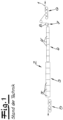
- Fig. 1 shows a known strip treatment device for the continuous treatment of a metal strip, namely a thermal treatment.
- This device has a tempering device 2, which is designed as a strip floatation furnace.
- the metal strip 1 passes through this strip floatation furnace 2 without contact, as the strip is floated between upper and lower nozzles, which are subjected to appropriate air pressure. Details are not shown.
- the strip floatation furnace 2 has a heating section 3 on the inlet side and a cooling section 4 on the outlet side.
- the heating section is generally composed of several heating zones 3', while the cooling section is generally composed of several cooling zones 4', whereby the individual zones can be controlled individually or separately.
- the metal strip is generally heated using air, so that the nozzles, e.g., the lower nozzles, can also perform temperature control in addition to their supporting function.
- cooling is generally also carried out by air or by a combination of air and water.
- the target temperature in the heating zone is, for example, approximately 550 °C to 570 °C.
- the heating zones therefore form heating and holding zones. It can be seen that the system has a set of tension rollers 5 on the inlet side, with which the strip tension is reduced, e.g. to a specific strip tension of, for example, 0.5 to 1 MPa.
- the metal strip 1 is center-controlled using a strip position control device 7, i.e. the position of the metal strip is controlled in the strip travel plane and transversely to the strip travel direction.
- the strip tension is then increased again to the usual line level of, for example, a specific 10 to 20 MPa using a set of tension rollers 6 on the outlet side. Due to the low specific strip tension within the strip floatation furnace, it is necessary to bring the metal strip 1 to the strip center using the strip position control device 7.
- Fig. 1 If one wants to increase the production capacity of such a Fig. 1 increase the system shown, it is generally necessary to extend the belt flotation furnace. With the Fig. 1 In the prior art system shown, there is a risk that, beyond a certain length of the strip floatation furnace, the strip position control device 7, e.g., the control roller 8, will no longer be sufficient, so that the strip path in the furnace may become unstable, i.e., the strip may run sideways or run into the furnace structure. This could lead to undesirable strip damage or strip breakage, so simply extending the strip floatation furnace is not advisable without additional measures.
- the strip position control device 7 e.g., the control roller 8
- the strip position control device 7 is therefore no longer arranged behind the tempering device 2 and consequently no longer behind the cooling section 4, but within the cooling section 4 itself.
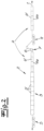
- the Fig. 2 and 3 show again a strip treatment device with a tempering device 2, which has an inlet-side heating section 3 and an outlet-side cooling section 4.
- a tension roller set 5 is provided and on the outlet side, another tension roller set 6 can be provided, which only in Fig. 3 , but not in Fig. 2 is shown.
- the heating section 3 is in turn composed of several heating zones 3', while the cooling section 4 is composed of several cooling zones 4'.
- the cooling section 4 is divided into two cooling section sections, namely a first cooling section section 4a and a subsequent second cooling section section 4b.
- the strip position control device 7 is now arranged according to the invention between the first cooling section section 4a and the second cooling section section 4b.
- the metal strip is heated in the heating section 3 with the heating and holding zones 3' in a basically known manner to the desired temperature, and the temperature can be maintained for a desired time.
- the heating section 3 therefore does not need to be modified compared to the prior art - apart from an extension.
- the heating section 3 is then followed by the first cooling section section 3a, with which the metal strip is cooled down in a first stage, preferably to a temperature of 100 °C to 200 °C, e.g.
- the strip center control is carried out using the strip center control device 7.
- This has a 90° control roller 8.
- Another tension roller set 9 is connected to increase the strip tension.
- the strip then passes through the second cooling section 4b, where it is cooled to the desired final temperature of, for example, 40 °C to 60 °C. In this way, production capacity can be increased without significantly increasing the free strip length, thus preventing an impermissible strip path in the furnace.
- a further strip position control device and/or another tension roller set can be connected to the second cooling section 4b. This is shown in Fig. 2 not shown.
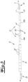
- Fig. 3 shows a modified embodiment of the invention, in which the strip center control device 7 is designed as a three-roller strip center control with three rollers 10. Furthermore, in Fig. 3 It is indicated that a further strip center control device 11 and a further tension roller set 6 can be arranged behind the second cooling section 4b.
- the additional strip center control device 11 behind the second cooling section 4b is useful because, in this embodiment, no tension roller set is arranged between the cooling sections 4a, 4b and therefore the second section 4b also operates with a lower strip tension.
- the furnace zones 3', 4' in the embodiment according to the invention have a total length which is greater than the length in the known embodiment according to Fig. 1
- the free strip length is not increased, since the strip center control 7 is already connected to the first cooling section 4a.
- This allows both the heating section 3 and the cooling section 4 to be significantly extended compared to the prior art.
- cooling section sections 4a and 4b are created, each of which is (significantly) shorter than the heating section 3.
Landscapes
- Chemical & Material Sciences (AREA)
- Engineering & Computer Science (AREA)
- Physics & Mathematics (AREA)
- Thermal Sciences (AREA)
- Crystallography & Structural Chemistry (AREA)
- Materials Engineering (AREA)
- Mechanical Engineering (AREA)
- Metallurgy (AREA)
- Organic Chemistry (AREA)
- Heat Treatment Of Strip Materials And Filament Materials (AREA)
- Registering, Tensioning, Guiding Webs, And Rollers Therefor (AREA)
- Tunnel Furnaces (AREA)
Claims (9)
- Dispositif de traitement continu d'une bande métallique (1), en particulier d'une bande métallique en aluminium ou en alliage d'aluminium ou en métal non ferreux ou en alliage métallique non ferreux,comportant au moins un dispositif de températion qui se présente sous forme d'un four oscillant à bande (2) dans lequel la bande métallique (1) est guidée en oscillantet un dispositif de réglage de position de bande (7) qui permet de contrôler ou de régler la position de la bande métallique (1) dans le plan de circulation de la bande et transversalement par rapport au sens de circulation de la bande,dans lequel le four oscillant à bande (2) présente au moins un segment de chauffage (3) côté entrée et un segment de refroidissement (4) côté sortie,caractérisé en ce quele dispositif de réglage de position de bande (7) est disposé dans le segment de chauffage (4),dans lequel le segment de refroidissement (4) est divisé en au moins une première section de segment de refroidissement (4a) et une seconde section de segment de refroidissement consécutive (4b), le dispositif de réglage de position de bande (7) étant disposé entre la première section de segment de refroidissement (4a) et la seconde section de segment de refroidissement (4b),dans laquelle le dispositif de réglage de position de bande présente un rouleau d'inversion réglable ou est réalisé en tant que tel ou est réalisé sous forme d'un système à rouleaux multiples.
- Dispositif selon la revendication 1, caractérisé en ce qu'un autre dispositif de réglage de position de bande (11) est disposé derrière la seconde section de segment de refroidissement.
- Dispositif selon la revendication 1 ou 2, caractérisé en ce que le dispositif de réglage de position de bande (7, 11) servant à régler la position de la bande présente un rouleau d'inversion réglable (8), par exemple un rouleau d'inversion de 90°, ou est réalisé en tant que tel.
- Dispositif selon la revendication 1 ou 2, caractérisé en ce que le dispositif de réglage de position de bande (7, 11) est réalisé sous forme d'un dispositif de réglage à trois rouleaux.
- Dispositif selon une des revendications 1 à 4, caractérisé en ce que, entre la première section de segment de refroidissement (4a) et la seconde section de segment de refroidissement (4b), un jeu de rouleaux de serrage (11) est disposé en aval du dispositif de réglage de position de bande (7).
- Dispositif selon une des revendications 1 à 5, caractérisé en ce que les rouleaux (8, 9) du dispositif de réglage de position de bande (7) et/ou du jeu de rouleaux de serrage (11) sont pourvus d'un revêtement résistant aux températures extrêmes.
- Procédé de traitement continu d'une bande métallique à l'aide d'un dispositif selon une des revendications 1 à 6, dans lequel la bande métallique est conduite pour traitement thermique en oscillant dans le segment de chauffage et le segment de refroidissement, caractérisé en ce que la position de la bande métallique est contrôlée ou réglée à l'aide d'un dispositif de réglage de position de bande disposé dans le segment de refroidissement,
dans lequel le dispositif de réglage de position de bande est disposé entre une première section de segment de refroidissement et une seconde section de segment de refroidissement. - Procédé selon la revendication 7, caractérisé en ce que la position de la bande est réglée par réglage PI avec une part P proportionnelle et une part I intégrale.
- Procédé selon la revendication 7 ou 8, caractérisé en ce que le dispositif de réglage de position de bande est disposé dans une partie du segment de refroidissement entre la première section de segment de refroidissement et la seconde section de segment de refroidissement, dans laquelle la température de la bande métallique va jusqu'à 200 °C, par exemple 100 °C à 200 °C, de préférence jusqu'à 150 °C, par exemple 120 °C à 150 °C
Priority Applications (1)
| Application Number | Priority Date | Filing Date | Title |
|---|---|---|---|
| PL13183368T PL2722112T3 (pl) | 2012-10-19 | 2013-09-06 | Urządzenie i sposób do ciągłej obróbki taśmy metalowej |
Applications Claiming Priority (1)
| Application Number | Priority Date | Filing Date | Title |
|---|---|---|---|
| DE102012110010.1A DE102012110010B4 (de) | 2012-10-19 | 2012-10-19 | Vorrichtung und Verfahren zur kontinuierlichen Behandlung eines Metallbandes |
Publications (3)
| Publication Number | Publication Date |
|---|---|
| EP2722112A1 EP2722112A1 (fr) | 2014-04-23 |
| EP2722112B1 EP2722112B1 (fr) | 2015-06-24 |
| EP2722112B2 true EP2722112B2 (fr) | 2025-03-26 |
Family
ID=49170558
Family Applications (1)
| Application Number | Title | Priority Date | Filing Date |
|---|---|---|---|
| EP13183368.3A Active EP2722112B2 (fr) | 2012-10-19 | 2013-09-06 | Dispositif et procédé destinés au traitement continu d'une bande métallique |
Country Status (10)
| Country | Link |
|---|---|
| US (1) | US10415113B2 (fr) |
| EP (1) | EP2722112B2 (fr) |
| KR (1) | KR102162942B1 (fr) |
| CN (1) | CN103773943B (fr) |
| CA (1) | CA2829532C (fr) |
| DE (1) | DE102012110010B4 (fr) |
| ES (1) | ES2543328T3 (fr) |
| HU (1) | HUE025366T2 (fr) |
| PL (1) | PL2722112T3 (fr) |
| RU (1) | RU2623520C2 (fr) |
Families Citing this family (8)
| Publication number | Priority date | Publication date | Assignee | Title |
|---|---|---|---|---|
| DE102012110010B4 (de) * | 2012-10-19 | 2016-09-01 | Bwg Bergwerk- Und Walzwerk-Maschinenbau Gmbh | Vorrichtung und Verfahren zur kontinuierlichen Behandlung eines Metallbandes |
| FR3027920B1 (fr) * | 2014-10-29 | 2019-03-29 | Fives Stein | Procede d'orientation de grains de tole d'acier, dispositif s'y rapportant, et installation mettant en oeuvre ce procede ou ce dispositif |
| DE102014118946B4 (de) * | 2014-12-18 | 2018-12-20 | Bwg Bergwerk- Und Walzwerk-Maschinenbau Gmbh | Vorrichtung und Verfahren zur kontinuierlichen Behandlung eines Metallbandes |
| CN104831053B (zh) * | 2015-05-25 | 2017-08-22 | 马钢(集团)控股有限公司 | 一种电工钢退火加热支撑方法 |
| KR102178232B1 (ko) | 2015-06-09 | 2020-11-12 | 노벨리스 인크. | 비-접촉 자기 조종 |
| US20190040491A1 (en) * | 2016-01-29 | 2019-02-07 | Corning Incorporated | Thermally treated metallic materials and related methods |
| DE102016102093B3 (de) | 2016-02-05 | 2017-06-14 | Bwg Bergwerk- Und Walzwerk-Maschinenbau Gmbh | Durchlaufkühlvorrichtung und Verfahren zum Abkühlen eines Metallbandes |
| DE102018100842B3 (de) * | 2018-01-16 | 2019-05-09 | Ebner Industrieofenbau Gmbh | Durchlaufofen für Aluminiumbänder |
Citations (4)
| Publication number | Priority date | Publication date | Assignee | Title |
|---|---|---|---|---|
| EP0068272A1 (fr) † | 1981-06-15 | 1983-01-05 | Daidotokushuko Kabushiki Kaisha | Appareil pour le transport de matière en bande |
| DE10303228B3 (de) † | 2003-01-28 | 2004-04-15 | Kramer, Carl, Prof. Dr.-Ing. | Vorrichtung zur Wärmebehandlung metallischer Bänder im Durchlauf |
| DE10326071A1 (de) † | 2003-06-10 | 2005-01-13 | Kramer, Carl, Prof. Dr.-Ing. | Umlenkvorrichtung für bewegte Bänder |
| WO2007138152A1 (fr) † | 2006-06-01 | 2007-12-06 | Outokumpu Oyj | Procédé pour contrôler une bande de métal dans un four de traitement thermique |
Family Cites Families (22)
| Publication number | Priority date | Publication date | Assignee | Title |
|---|---|---|---|---|
| US4218002A (en) | 1979-05-31 | 1980-08-19 | Olin Corporation | Strip material center guide assembly |
| JPS5848641A (ja) * | 1981-09-16 | 1983-03-22 | Daido Steel Co Ltd | 連続加熱処理炉 |
| DE3307499C3 (de) | 1983-03-03 | 1995-02-09 | Elmeg | Regeleinrichtung zur kanten- oder mittengenauen Führung von bandförmigen Materialbahnen |
| JPS6270527A (ja) * | 1985-09-25 | 1987-04-01 | Mitsubishi Heavy Ind Ltd | 金属ストリツプの連続焼鈍炉 |
| JPS62235429A (ja) * | 1986-04-04 | 1987-10-15 | Daido Steel Co Ltd | フロ−テイング式熱処理炉における金属帯状材料のセンタリング装置 |
| FR2688802B1 (fr) | 1992-03-19 | 1994-09-30 | Stein Heurtey | Procede de traitement thermique de bandes metalliques. |
| DE4313543C1 (de) | 1993-04-24 | 1994-04-07 | Vits Maschinenbau Gmbh | Verfahren und Vorrichtung zur Wärmebehandlung kontinuierlich durchlaufender Metallbänder |
| JP3489240B2 (ja) * | 1995-01-13 | 2004-01-19 | 大同特殊鋼株式会社 | フローティング炉 |
| US5648539A (en) | 1996-02-29 | 1997-07-15 | Xerox Corporation | Low temperature arylamine processes |
| FR2746112B1 (fr) | 1996-03-13 | 1998-06-05 | Procede de traitement thermique en continu de bandes metalliques dans des atmospheres de nature differente | |
| DE19719994B4 (de) | 1997-05-13 | 2005-01-05 | Bwg Bergwerk- Und Walzwerk-Maschinenbau Gmbh | Verfahren zur Beeinflussung der Spannungsverteilung in Metallbändern oder -tafeln aus insbesondere nichtferromagnetischem Material |
| DE19804184A1 (de) | 1998-02-03 | 1999-08-05 | Kramer Carl | Vorrichtung zur schwebenden Führung von Bändern |
| EP1008661A3 (fr) | 1998-12-12 | 2000-06-28 | Sundwig GmbH | Installation pour traiter des bandes métalliques en marche continue le long d'une direction principale de transport |
| FR2796139B1 (fr) | 1999-07-06 | 2001-11-09 | Stein Heurtey | Procede et dispositif de suppression de la vibration des bandes dans des zones de soufflage de gaz, notamment des zones de refroidissement |
| DE10163070A1 (de) * | 2001-12-20 | 2003-07-03 | Sms Demag Ag | Verfahren und Einrichtung zum kontrollierten Richten und Kühlen von aus einem Warmband-Walzwerk auslaufendem breiten Metallband, insbesondere von Stahlband oder Blech |
| DE10337502B4 (de) | 2003-08-14 | 2006-03-30 | Kramer, Carl, Prof. Dr.-Ing. | Verfahren zum Betrieb einer Durchlauf-Wärmebehandlungsanlage für Warenbahnen und Bänder mit überwiegend konvektiver Wärmeübertragung |
| FR2897620B1 (fr) | 2006-02-21 | 2008-04-04 | Stein Heurtey | Procede et dispositif de refroidissement et de stabilisation de bande dans une ligne continue |
| DE102008010062A1 (de) | 2007-06-22 | 2008-12-24 | Sms Demag Ag | Verfahren zum Warmwalzen und zur Wärmebehandlung eines Bandes aus Stahl |
| CN102137943B (zh) * | 2009-04-22 | 2013-01-09 | 新日铁工程技术株式会社 | 冷轧钢板的制造方法及其制造设备 |
| EP2468905A1 (fr) | 2010-12-22 | 2012-06-27 | Siemens VAI Metals Technologies GmbH | Tunnel de refroidissement doté d'un système de stockage à bande verticale intégré |
| CN202072725U (zh) * | 2011-05-03 | 2011-12-14 | 佛山市高明基业冷轧钢板有限公司 | 一种具有生产退火板和电工钢功能的复合机组 |
| DE102012110010B4 (de) * | 2012-10-19 | 2016-09-01 | Bwg Bergwerk- Und Walzwerk-Maschinenbau Gmbh | Vorrichtung und Verfahren zur kontinuierlichen Behandlung eines Metallbandes |
-
2012
- 2012-10-19 DE DE102012110010.1A patent/DE102012110010B4/de not_active Revoked
-
2013
- 2013-09-06 PL PL13183368T patent/PL2722112T3/pl unknown
- 2013-09-06 ES ES13183368.3T patent/ES2543328T3/es active Active
- 2013-09-06 HU HUE13183368A patent/HUE025366T2/en unknown
- 2013-09-06 EP EP13183368.3A patent/EP2722112B2/fr active Active
- 2013-10-08 CA CA2829532A patent/CA2829532C/fr active Active
- 2013-10-16 KR KR1020130123296A patent/KR102162942B1/ko active Active
- 2013-10-17 US US14/056,372 patent/US10415113B2/en active Active
- 2013-10-18 RU RU2013146678A patent/RU2623520C2/ru active
- 2013-10-18 CN CN201310489275.1A patent/CN103773943B/zh not_active Expired - Fee Related
Patent Citations (4)
| Publication number | Priority date | Publication date | Assignee | Title |
|---|---|---|---|---|
| EP0068272A1 (fr) † | 1981-06-15 | 1983-01-05 | Daidotokushuko Kabushiki Kaisha | Appareil pour le transport de matière en bande |
| DE10303228B3 (de) † | 2003-01-28 | 2004-04-15 | Kramer, Carl, Prof. Dr.-Ing. | Vorrichtung zur Wärmebehandlung metallischer Bänder im Durchlauf |
| DE10326071A1 (de) † | 2003-06-10 | 2005-01-13 | Kramer, Carl, Prof. Dr.-Ing. | Umlenkvorrichtung für bewegte Bänder |
| WO2007138152A1 (fr) † | 2006-06-01 | 2007-12-06 | Outokumpu Oyj | Procédé pour contrôler une bande de métal dans un four de traitement thermique |
Also Published As
| Publication number | Publication date |
|---|---|
| CN103773943B (zh) | 2018-02-06 |
| EP2722112A1 (fr) | 2014-04-23 |
| CN103773943A (zh) | 2014-05-07 |
| KR102162942B1 (ko) | 2020-10-07 |
| KR20140050552A (ko) | 2014-04-29 |
| CA2829532A1 (fr) | 2014-04-19 |
| RU2013146678A (ru) | 2015-04-27 |
| ES2543328T3 (es) | 2015-08-18 |
| US10415113B2 (en) | 2019-09-17 |
| RU2623520C2 (ru) | 2017-06-27 |
| EP2722112B1 (fr) | 2015-06-24 |
| CA2829532C (fr) | 2020-03-10 |
| PL2722112T3 (pl) | 2015-11-30 |
| DE102012110010B4 (de) | 2016-09-01 |
| US20140110890A1 (en) | 2014-04-24 |
| HUE025366T2 (en) | 2016-02-29 |
| DE102012110010A1 (de) | 2014-04-24 |
Similar Documents
| Publication | Publication Date | Title |
|---|---|---|
| EP2722112B2 (fr) | Dispositif et procédé destinés au traitement continu d'une bande métallique | |
| EP3234204B1 (fr) | Dispositif et procédé de traitement en continu d'une bande métallique | |
| EP1955786B1 (fr) | Procédé destinés à aplanir des bandes en métal | |
| EP2445659B1 (fr) | Procédé et dispositif d'usinage d'une brame | |
| DE102016102093B3 (de) | Durchlaufkühlvorrichtung und Verfahren zum Abkühlen eines Metallbandes | |
| EP3221487B1 (fr) | Procédé et dispositif pour revêtir une bande métallique | |
| EP2310152B1 (fr) | Procédé permettant le guidage longitudinal d'un produit laminé, en particulier d'une bande d'acier laminée à chaud, et laminoir à chaud pour la mise en oeuvre de ce procédé | |
| EP2934778B1 (fr) | Dispositif de refroidissement d'un produit laminé | |
| DE102009012334B4 (de) | Verfahren zur Kühlmittelaufbringung auf einen gegossenen Metallstrang in einer Stranggießanlage und Stranggießanlage dazu | |
| DE102018215100A1 (de) | Vakuumbeschichtungsanlage, und Verfahren zum Beschichten eines bandförmigen Materials | |
| WO2010127820A1 (fr) | Rampe de pulvérisation, section et procédé pour appliquer un fluide sur un produit | |
| DE102013214344A1 (de) | Kühlstrecke und Verfahren zum Kühlen von warmgewalztem Metallband | |
| DE102021203170A1 (de) | Verfahren zum Führen und Zentrieren eines metallenen Walzguts in einer Walzstraße | |
| DE2723720A1 (de) | Vorrichtung zum aufrechterhalten einer waehrend eines richtvorganges auf ein metallband ausgeuebten, bestimmten zugspannung | |
| DE2102800B2 (de) | Anlage zur thermischen behandlung von walzerzeugnissen im kuehlmittelstrom | |
| EP2842646A1 (fr) | Dispositif et procédé destinés à réguler la température de rouleaux | |
| EP3826781B1 (fr) | Procédé et dispositif de détermination du contour de bande latéral d'une bande métallique en mouvement | |
| DE102017213854A1 (de) | Anlage und Verfahren zur Herstellung eines metallischen Produkts | |
| EP3307448B1 (fr) | Procédé et dispositif servant à réguler un paramètre d'un produit à laminer | |
| EP3535071B1 (fr) | Procédé et installation de production d'une bande métallique | |
| DE19953915A1 (de) | Verfahren und Vorrichtung zum Bearbeiten eines Warmbandes auf dem Auslaufrollgang einer Warmbandstraße | |
| DE102010063093B4 (de) | Vorrichtung und Verfahren zum horizontalen Gießen von Metallbändern | |
| DE102008008648B3 (de) | Vorrichtung zur Abkühlung eines Werkstückes | |
| DE102023211833A1 (de) | Vorrichtung und Verfahren zum Kühlen eines Gießstrangs in einer Stranggießanlage | |
| WO2018138038A1 (fr) | Installation de laminage direct et procédé de traitement d'une pièce à l'aide d'une telle installation |
Legal Events
| Date | Code | Title | Description |
|---|---|---|---|
| PUAI | Public reference made under article 153(3) epc to a published international application that has entered the european phase |
Free format text: ORIGINAL CODE: 0009012 |
|
| AK | Designated contracting states |
Kind code of ref document: A1 Designated state(s): AL AT BE BG CH CY CZ DE DK EE ES FI FR GB GR HR HU IE IS IT LI LT LU LV MC MK MT NL NO PL PT RO RS SE SI SK SM TR |
|
| AX | Request for extension of the european patent |
Extension state: BA ME |
|
| 17P | Request for examination filed |
Effective date: 20140326 |
|
| RBV | Designated contracting states (corrected) |
Designated state(s): AL AT BE BG CH CY CZ DE DK EE ES FI FR GB GR HR HU IE IS IT LI LT LU LV MC MK MT NL NO PL PT RO RS SE SI SK SM TR |
|
| REG | Reference to a national code |
Ref country code: DE Ref legal event code: R079 Ref document number: 502013000776 Country of ref document: DE Free format text: PREVIOUS MAIN CLASS: B21B0039000000 Ipc: C21D0009560000 |
|
| GRAP | Despatch of communication of intention to grant a patent |
Free format text: ORIGINAL CODE: EPIDOSNIGR1 |
|
| RIC1 | Information provided on ipc code assigned before grant |
Ipc: C21D 11/00 20060101ALI20150211BHEP Ipc: B21B 39/00 20060101ALI20150211BHEP Ipc: C21D 9/54 20060101ALI20150211BHEP Ipc: C21D 9/63 20060101ALI20150211BHEP Ipc: C21D 9/56 20060101AFI20150211BHEP |
|
| INTG | Intention to grant announced |
Effective date: 20150309 |
|
| GRAS | Grant fee paid |
Free format text: ORIGINAL CODE: EPIDOSNIGR3 |
|
| GRAA | (expected) grant |
Free format text: ORIGINAL CODE: 0009210 |
|
| AK | Designated contracting states |
Kind code of ref document: B1 Designated state(s): AL AT BE BG CH CY CZ DE DK EE ES FI FR GB GR HR HU IE IS IT LI LT LU LV MC MK MT NL NO PL PT RO RS SE SI SK SM TR |
|
| REG | Reference to a national code |
Ref country code: GB Ref legal event code: FG4D Free format text: NOT ENGLISH |
|
| REG | Reference to a national code |
Ref country code: CH Ref legal event code: EP |
|
| REG | Reference to a national code |
Ref country code: AT Ref legal event code: REF Ref document number: 732917 Country of ref document: AT Kind code of ref document: T Effective date: 20150715 |
|
| REG | Reference to a national code |
Ref country code: IE Ref legal event code: FG4D Free format text: LANGUAGE OF EP DOCUMENT: GERMAN |
|
| REG | Reference to a national code |
Ref country code: DE Ref legal event code: R096 Ref document number: 502013000776 Country of ref document: DE |
|
| REG | Reference to a national code |
Ref country code: SE Ref legal event code: TRGR |
|
| REG | Reference to a national code |
Ref country code: ES Ref legal event code: FG2A Ref document number: 2543328 Country of ref document: ES Kind code of ref document: T3 Effective date: 20150818 |
|
| REG | Reference to a national code |
Ref country code: FR Ref legal event code: PLFP Year of fee payment: 3 |
|
| RAP2 | Party data changed (patent owner data changed or rights of a patent transferred) |
Owner name: BWG BERGWERK- UND WALZWERK-MASCHINENBAU GMBH |
|
| REG | Reference to a national code |
Ref country code: NL Ref legal event code: FP |
|
| PG25 | Lapsed in a contracting state [announced via postgrant information from national office to epo] |
Ref country code: LT Free format text: LAPSE BECAUSE OF FAILURE TO SUBMIT A TRANSLATION OF THE DESCRIPTION OR TO PAY THE FEE WITHIN THE PRESCRIBED TIME-LIMIT Effective date: 20150624 Ref country code: HR Free format text: LAPSE BECAUSE OF FAILURE TO SUBMIT A TRANSLATION OF THE DESCRIPTION OR TO PAY THE FEE WITHIN THE PRESCRIBED TIME-LIMIT Effective date: 20150624 Ref country code: NO Free format text: LAPSE BECAUSE OF FAILURE TO SUBMIT A TRANSLATION OF THE DESCRIPTION OR TO PAY THE FEE WITHIN THE PRESCRIBED TIME-LIMIT Effective date: 20150924 |
|
| REG | Reference to a national code |
Ref country code: LT Ref legal event code: MG4D |
|
| PG25 | Lapsed in a contracting state [announced via postgrant information from national office to epo] |
Ref country code: LV Free format text: LAPSE BECAUSE OF FAILURE TO SUBMIT A TRANSLATION OF THE DESCRIPTION OR TO PAY THE FEE WITHIN THE PRESCRIBED TIME-LIMIT Effective date: 20150624 Ref country code: BG Free format text: LAPSE BECAUSE OF FAILURE TO SUBMIT A TRANSLATION OF THE DESCRIPTION OR TO PAY THE FEE WITHIN THE PRESCRIBED TIME-LIMIT Effective date: 20150924 Ref country code: RS Free format text: LAPSE BECAUSE OF FAILURE TO SUBMIT A TRANSLATION OF THE DESCRIPTION OR TO PAY THE FEE WITHIN THE PRESCRIBED TIME-LIMIT Effective date: 20150624 |
|
| REG | Reference to a national code |
Ref country code: PL Ref legal event code: T3 |
|
| REG | Reference to a national code |
Ref country code: GR Ref legal event code: EP Ref document number: 20150401891 Country of ref document: GR Effective date: 20151022 |
|
| PG25 | Lapsed in a contracting state [announced via postgrant information from national office to epo] |
Ref country code: EE Free format text: LAPSE BECAUSE OF FAILURE TO SUBMIT A TRANSLATION OF THE DESCRIPTION OR TO PAY THE FEE WITHIN THE PRESCRIBED TIME-LIMIT Effective date: 20150624 |
|
| PG25 | Lapsed in a contracting state [announced via postgrant information from national office to epo] |
Ref country code: RO Free format text: LAPSE BECAUSE OF NON-PAYMENT OF DUE FEES Effective date: 20150624 Ref country code: IS Free format text: LAPSE BECAUSE OF FAILURE TO SUBMIT A TRANSLATION OF THE DESCRIPTION OR TO PAY THE FEE WITHIN THE PRESCRIBED TIME-LIMIT Effective date: 20151024 Ref country code: CZ Free format text: LAPSE BECAUSE OF FAILURE TO SUBMIT A TRANSLATION OF THE DESCRIPTION OR TO PAY THE FEE WITHIN THE PRESCRIBED TIME-LIMIT Effective date: 20150624 Ref country code: PT Free format text: LAPSE BECAUSE OF FAILURE TO SUBMIT A TRANSLATION OF THE DESCRIPTION OR TO PAY THE FEE WITHIN THE PRESCRIBED TIME-LIMIT Effective date: 20151026 Ref country code: SK Free format text: LAPSE BECAUSE OF FAILURE TO SUBMIT A TRANSLATION OF THE DESCRIPTION OR TO PAY THE FEE WITHIN THE PRESCRIBED TIME-LIMIT Effective date: 20150624 |
|
| REG | Reference to a national code |
Ref country code: HU Ref legal event code: AG4A Ref document number: E025366 Country of ref document: HU |
|
| REG | Reference to a national code |
Ref country code: DE Ref legal event code: R026 Ref document number: 502013000776 Country of ref document: DE |
|
| PLBI | Opposition filed |
Free format text: ORIGINAL CODE: 0009260 |
|
| PLBI | Opposition filed |
Free format text: ORIGINAL CODE: 0009260 |
|
| 26 | Opposition filed |
Opponent name: NOVELIS INC. Effective date: 20160322 |
|
| PG25 | Lapsed in a contracting state [announced via postgrant information from national office to epo] |
Ref country code: MC Free format text: LAPSE BECAUSE OF FAILURE TO SUBMIT A TRANSLATION OF THE DESCRIPTION OR TO PAY THE FEE WITHIN THE PRESCRIBED TIME-LIMIT Effective date: 20150624 Ref country code: LU Free format text: LAPSE BECAUSE OF FAILURE TO SUBMIT A TRANSLATION OF THE DESCRIPTION OR TO PAY THE FEE WITHIN THE PRESCRIBED TIME-LIMIT Effective date: 20150906 Ref country code: DK Free format text: LAPSE BECAUSE OF FAILURE TO SUBMIT A TRANSLATION OF THE DESCRIPTION OR TO PAY THE FEE WITHIN THE PRESCRIBED TIME-LIMIT Effective date: 20150624 |
|
| PLAX | Notice of opposition and request to file observation + time limit sent |
Free format text: ORIGINAL CODE: EPIDOSNOBS2 |
|
| 26 | Opposition filed |
Opponent name: EBNER INDUSTRIEOFENBAU GMBH Effective date: 20160324 |
|
| PLAS | Information related to reply of patent proprietor to notice(s) of opposition deleted |
Free format text: ORIGINAL CODE: EPIDOSDOBS3 |
|
| PLBB | Reply of patent proprietor to notice(s) of opposition received |
Free format text: ORIGINAL CODE: EPIDOSNOBS3 |
|
| REG | Reference to a national code |
Ref country code: IE Ref legal event code: MM4A |
|
| PG25 | Lapsed in a contracting state [announced via postgrant information from national office to epo] |
Ref country code: IE Free format text: LAPSE BECAUSE OF NON-PAYMENT OF DUE FEES Effective date: 20150906 |
|
| PG25 | Lapsed in a contracting state [announced via postgrant information from national office to epo] |
Ref country code: SI Free format text: LAPSE BECAUSE OF FAILURE TO SUBMIT A TRANSLATION OF THE DESCRIPTION OR TO PAY THE FEE WITHIN THE PRESCRIBED TIME-LIMIT Effective date: 20150624 |
|
| PLBB | Reply of patent proprietor to notice(s) of opposition received |
Free format text: ORIGINAL CODE: EPIDOSNOBS3 |
|
| REG | Reference to a national code |
Ref country code: FR Ref legal event code: PLFP Year of fee payment: 4 |
|
| PG25 | Lapsed in a contracting state [announced via postgrant information from national office to epo] |
Ref country code: MT Free format text: LAPSE BECAUSE OF FAILURE TO SUBMIT A TRANSLATION OF THE DESCRIPTION OR TO PAY THE FEE WITHIN THE PRESCRIBED TIME-LIMIT Effective date: 20150624 |
|
| REG | Reference to a national code |
Ref country code: CH Ref legal event code: PL |
|
| PG25 | Lapsed in a contracting state [announced via postgrant information from national office to epo] |
Ref country code: CY Free format text: LAPSE BECAUSE OF FAILURE TO SUBMIT A TRANSLATION OF THE DESCRIPTION OR TO PAY THE FEE WITHIN THE PRESCRIBED TIME-LIMIT Effective date: 20150624 |
|
| PG25 | Lapsed in a contracting state [announced via postgrant information from national office to epo] |
Ref country code: CH Free format text: LAPSE BECAUSE OF NON-PAYMENT OF DUE FEES Effective date: 20160930 Ref country code: LI Free format text: LAPSE BECAUSE OF NON-PAYMENT OF DUE FEES Effective date: 20160930 |
|
| REG | Reference to a national code |
Ref country code: FR Ref legal event code: PLFP Year of fee payment: 5 |
|
| RDAF | Communication despatched that patent is revoked |
Free format text: ORIGINAL CODE: EPIDOSNREV1 |
|
| STAA | Information on the status of an ep patent application or granted ep patent |
Free format text: STATUS: THE PATENT HAS BEEN GRANTED |
|
| APBM | Appeal reference recorded |
Free format text: ORIGINAL CODE: EPIDOSNREFNO |
|
| APBP | Date of receipt of notice of appeal recorded |
Free format text: ORIGINAL CODE: EPIDOSNNOA2O |
|
| APAH | Appeal reference modified |
Free format text: ORIGINAL CODE: EPIDOSCREFNO |
|
| PG25 | Lapsed in a contracting state [announced via postgrant information from national office to epo] |
Ref country code: SM Free format text: LAPSE BECAUSE OF FAILURE TO SUBMIT A TRANSLATION OF THE DESCRIPTION OR TO PAY THE FEE WITHIN THE PRESCRIBED TIME-LIMIT Effective date: 20150624 |
|
| PG25 | Lapsed in a contracting state [announced via postgrant information from national office to epo] |
Ref country code: MK Free format text: LAPSE BECAUSE OF FAILURE TO SUBMIT A TRANSLATION OF THE DESCRIPTION OR TO PAY THE FEE WITHIN THE PRESCRIBED TIME-LIMIT Effective date: 20150624 |
|
| APBQ | Date of receipt of statement of grounds of appeal recorded |
Free format text: ORIGINAL CODE: EPIDOSNNOA3O |
|
| REG | Reference to a national code |
Ref country code: FR Ref legal event code: PLFP Year of fee payment: 6 |
|
| APAH | Appeal reference modified |
Free format text: ORIGINAL CODE: EPIDOSCREFNO |
|
| PG25 | Lapsed in a contracting state [announced via postgrant information from national office to epo] |
Ref country code: AL Free format text: LAPSE BECAUSE OF FAILURE TO SUBMIT A TRANSLATION OF THE DESCRIPTION OR TO PAY THE FEE WITHIN THE PRESCRIBED TIME-LIMIT Effective date: 20150624 |
|
| PGFP | Annual fee paid to national office [announced via postgrant information from national office to epo] |
Ref country code: NO Payment date: 20180724 Year of fee payment: 10 |
|
| 29U | Proceedings interrupted after grant according to rule 142 epc |
Effective date: 20191001 |
|
| 29W | Proceedings resumed after grant [after interruption of proceedings according to rule 142 epc] |
Effective date: 20201201 |
|
| REG | Reference to a national code |
Ref country code: DE Ref legal event code: R082 Ref document number: 502013000776 Country of ref document: DE Representative=s name: ANDREJEWSKI HONKE PATENT- UND RECHTSANWAELTE P, DE Ref country code: DE Ref legal event code: R081 Ref document number: 502013000776 Country of ref document: DE Owner name: REDEX S.A., FR Free format text: FORMER OWNER: BWG BERGWERK- UND WALZWERK-MASCHINENBAU GMBH, 47051 DUISBURG, DE |
|
| REG | Reference to a national code |
Ref country code: GB Ref legal event code: 732E Free format text: REGISTERED BETWEEN 20210603 AND 20210609 |
|
| REG | Reference to a national code |
Ref country code: AT Ref legal event code: PC Ref document number: 732917 Country of ref document: AT Kind code of ref document: T Owner name: REDEX, FR Effective date: 20210618 |
|
| RAP2 | Party data changed (patent owner data changed or rights of a patent transferred) |
Owner name: REDEX S.A. |
|
| APBU | Appeal procedure closed |
Free format text: ORIGINAL CODE: EPIDOSNNOA9O |
|
| PG25 | Lapsed in a contracting state [announced via postgrant information from national office to epo] |
Ref country code: PL Free format text: LAPSE BECAUSE OF NON-PAYMENT OF DUE FEES Effective date: 20190906 |
|
| PLAY | Examination report in opposition despatched + time limit |
Free format text: ORIGINAL CODE: EPIDOSNORE2 |
|
| PLBC | Reply to examination report in opposition received |
Free format text: ORIGINAL CODE: EPIDOSNORE3 |
|
| PLAY | Examination report in opposition despatched + time limit |
Free format text: ORIGINAL CODE: EPIDOSNORE2 |
|
| PLAB | Opposition data, opponent's data or that of the opponent's representative modified |
Free format text: ORIGINAL CODE: 0009299OPPO |
|
| PLBC | Reply to examination report in opposition received |
Free format text: ORIGINAL CODE: EPIDOSNORE3 |
|
| R26 | Opposition filed (corrected) |
Opponent name: NOVELIS INC. Effective date: 20160322 |
|
| PGFP | Annual fee paid to national office [announced via postgrant information from national office to epo] |
Ref country code: TR Payment date: 20230905 Year of fee payment: 11 Ref country code: NL Payment date: 20230920 Year of fee payment: 11 Ref country code: FI Payment date: 20230920 Year of fee payment: 11 Ref country code: AT Payment date: 20230921 Year of fee payment: 11 |
|
| PGFP | Annual fee paid to national office [announced via postgrant information from national office to epo] |
Ref country code: SE Payment date: 20230920 Year of fee payment: 11 Ref country code: HU Payment date: 20230922 Year of fee payment: 11 Ref country code: GR Payment date: 20230921 Year of fee payment: 11 |
|
| PGFP | Annual fee paid to national office [announced via postgrant information from national office to epo] |
Ref country code: ES Payment date: 20231124 Year of fee payment: 11 |
|
| RIC2 | Information provided on ipc code assigned after grant |
Ipc: C21D 9/63 20060101ALI20231220BHEP Ipc: C21D 9/56 20060101ALI20231220BHEP Ipc: C22F 1/04 20060101ALI20231220BHEP Ipc: C21D 9/46 20060101AFI20231220BHEP |
|
| PGFP | Annual fee paid to national office [announced via postgrant information from national office to epo] |
Ref country code: IT Payment date: 20230927 Year of fee payment: 11 |
|
| PUAH | Patent maintained in amended form |
Free format text: ORIGINAL CODE: 0009272 |
|
| STAA | Information on the status of an ep patent application or granted ep patent |
Free format text: STATUS: PATENT MAINTAINED AS AMENDED |
|
| 27A | Patent maintained in amended form |
Effective date: 20250326 |
|
| AK | Designated contracting states |
Kind code of ref document: B2 Designated state(s): AL AT BE BG CH CY CZ DE DK EE ES FI FR GB GR HR HU IE IS IT LI LT LU LV MC MK MT NL NO PL PT RO RS SE SI SK SM TR |
|
| REG | Reference to a national code |
Ref country code: DE Ref legal event code: R102 Ref document number: 502013000776 Country of ref document: DE |
|
| PG25 | Lapsed in a contracting state [announced via postgrant information from national office to epo] |
Ref country code: FI Free format text: LAPSE BECAUSE OF NON-PAYMENT OF DUE FEES Effective date: 20240906 |
|
| REG | Reference to a national code |
Ref country code: SE Ref legal event code: EUG |
|
| REG | Reference to a national code |
Ref country code: NL Ref legal event code: MM Effective date: 20241001 |
|
| REG | Reference to a national code |
Ref country code: AT Ref legal event code: MM01 Ref document number: 732917 Country of ref document: AT Kind code of ref document: T Effective date: 20240906 |
|
| PG25 | Lapsed in a contracting state [announced via postgrant information from national office to epo] |
Ref country code: NL Free format text: LAPSE BECAUSE OF NON-PAYMENT OF DUE FEES Effective date: 20241001 |
|
| PG25 | Lapsed in a contracting state [announced via postgrant information from national office to epo] |
Ref country code: HU Free format text: LAPSE BECAUSE OF NON-PAYMENT OF DUE FEES Effective date: 20240907 |
|
| PG25 | Lapsed in a contracting state [announced via postgrant information from national office to epo] |
Ref country code: IT Free format text: LAPSE BECAUSE OF NON-PAYMENT OF DUE FEES Effective date: 20240906 |
|
| PG25 | Lapsed in a contracting state [announced via postgrant information from national office to epo] |
Ref country code: GR Free format text: LAPSE BECAUSE OF FAILURE TO SUBMIT A TRANSLATION OF THE DESCRIPTION OR TO PAY THE FEE WITHIN THE PRESCRIBED TIME-LIMIT Effective date: 20250627 |
|
| PG25 | Lapsed in a contracting state [announced via postgrant information from national office to epo] |
Ref country code: AT Free format text: LAPSE BECAUSE OF NON-PAYMENT OF DUE FEES Effective date: 20240906 |
|
| PG25 | Lapsed in a contracting state [announced via postgrant information from national office to epo] |
Ref country code: ES Free format text: LAPSE BECAUSE OF FAILURE TO SUBMIT A TRANSLATION OF THE DESCRIPTION OR TO PAY THE FEE WITHIN THE PRESCRIBED TIME-LIMIT Effective date: 20250326 |
|
| PGFP | Annual fee paid to national office [announced via postgrant information from national office to epo] |
Ref country code: DE Payment date: 20250919 Year of fee payment: 13 |
|
| PG25 | Lapsed in a contracting state [announced via postgrant information from national office to epo] |
Ref country code: SE Free format text: LAPSE BECAUSE OF NON-PAYMENT OF DUE FEES Effective date: 20240907 |
|
| PGFP | Annual fee paid to national office [announced via postgrant information from national office to epo] |
Ref country code: BE Payment date: 20250918 Year of fee payment: 13 Ref country code: GB Payment date: 20250918 Year of fee payment: 13 |
|
| PGFP | Annual fee paid to national office [announced via postgrant information from national office to epo] |
Ref country code: FR Payment date: 20250922 Year of fee payment: 13 |