EP2711233A2 - Stromversorgungsmanagementvorrichtung und Verfahren dafür - Google Patents
Stromversorgungsmanagementvorrichtung und Verfahren dafür Download PDFInfo
- Publication number
- EP2711233A2 EP2711233A2 EP13185678.3A EP13185678A EP2711233A2 EP 2711233 A2 EP2711233 A2 EP 2711233A2 EP 13185678 A EP13185678 A EP 13185678A EP 2711233 A2 EP2711233 A2 EP 2711233A2
- Authority
- EP
- European Patent Office
- Prior art keywords
- power
- onboard
- energy storage
- vehicle
- storage device
- Prior art date
- Legal status (The legal status is an assumption and is not a legal conclusion. Google has not performed a legal analysis and makes no representation as to the accuracy of the status listed.)
- Pending
Links
Images


Classifications
-
- B—PERFORMING OPERATIONS; TRANSPORTING
- B60—VEHICLES IN GENERAL
- B60L—PROPULSION OF ELECTRICALLY-PROPELLED VEHICLES; SUPPLYING ELECTRIC POWER FOR AUXILIARY EQUIPMENT OF ELECTRICALLY-PROPELLED VEHICLES; ELECTRODYNAMIC BRAKE SYSTEMS FOR VEHICLES IN GENERAL; MAGNETIC SUSPENSION OR LEVITATION FOR VEHICLES; MONITORING OPERATING VARIABLES OF ELECTRICALLY-PROPELLED VEHICLES; ELECTRIC SAFETY DEVICES FOR ELECTRICALLY-PROPELLED VEHICLES
- B60L50/00—Electric propulsion with power supplied within the vehicle
- B60L50/50—Electric propulsion with power supplied within the vehicle using propulsion power supplied by batteries or fuel cells
- B60L50/53—Electric propulsion with power supplied within the vehicle using propulsion power supplied by batteries or fuel cells in combination with an external power supply, e.g. from overhead contact lines
-
- B—PERFORMING OPERATIONS; TRANSPORTING
- B60—VEHICLES IN GENERAL
- B60L—PROPULSION OF ELECTRICALLY-PROPELLED VEHICLES; SUPPLYING ELECTRIC POWER FOR AUXILIARY EQUIPMENT OF ELECTRICALLY-PROPELLED VEHICLES; ELECTRODYNAMIC BRAKE SYSTEMS FOR VEHICLES IN GENERAL; MAGNETIC SUSPENSION OR LEVITATION FOR VEHICLES; MONITORING OPERATING VARIABLES OF ELECTRICALLY-PROPELLED VEHICLES; ELECTRIC SAFETY DEVICES FOR ELECTRICALLY-PROPELLED VEHICLES
- B60L15/00—Methods, circuits, or devices for controlling the traction-motor speed of electrically-propelled vehicles
- B60L15/20—Methods, circuits, or devices for controlling the traction-motor speed of electrically-propelled vehicles for control of the vehicle or its driving motor to achieve a desired performance, e.g. speed, torque, programmed variation of speed
- B60L15/2045—Methods, circuits, or devices for controlling the traction-motor speed of electrically-propelled vehicles for control of the vehicle or its driving motor to achieve a desired performance, e.g. speed, torque, programmed variation of speed for optimising the use of energy
-
- B—PERFORMING OPERATIONS; TRANSPORTING
- B60—VEHICLES IN GENERAL
- B60L—PROPULSION OF ELECTRICALLY-PROPELLED VEHICLES; SUPPLYING ELECTRIC POWER FOR AUXILIARY EQUIPMENT OF ELECTRICALLY-PROPELLED VEHICLES; ELECTRODYNAMIC BRAKE SYSTEMS FOR VEHICLES IN GENERAL; MAGNETIC SUSPENSION OR LEVITATION FOR VEHICLES; MONITORING OPERATING VARIABLES OF ELECTRICALLY-PROPELLED VEHICLES; ELECTRIC SAFETY DEVICES FOR ELECTRICALLY-PROPELLED VEHICLES
- B60L50/00—Electric propulsion with power supplied within the vehicle
- B60L50/90—Electric propulsion with power supplied within the vehicle using propulsion power supplied by specific means not covered by groups B60L50/10 - B60L50/50, e.g. by direct conversion of thermal nuclear energy into electricity
-
- B—PERFORMING OPERATIONS; TRANSPORTING
- B60—VEHICLES IN GENERAL
- B60L—PROPULSION OF ELECTRICALLY-PROPELLED VEHICLES; SUPPLYING ELECTRIC POWER FOR AUXILIARY EQUIPMENT OF ELECTRICALLY-PROPELLED VEHICLES; ELECTRODYNAMIC BRAKE SYSTEMS FOR VEHICLES IN GENERAL; MAGNETIC SUSPENSION OR LEVITATION FOR VEHICLES; MONITORING OPERATING VARIABLES OF ELECTRICALLY-PROPELLED VEHICLES; ELECTRIC SAFETY DEVICES FOR ELECTRICALLY-PROPELLED VEHICLES
- B60L8/00—Electric propulsion with power supply from forces of nature, e.g. sun or wind
- B60L8/003—Converting light into electric energy, e.g. by using photo-voltaic systems
-
- B—PERFORMING OPERATIONS; TRANSPORTING
- B60—VEHICLES IN GENERAL
- B60L—PROPULSION OF ELECTRICALLY-PROPELLED VEHICLES; SUPPLYING ELECTRIC POWER FOR AUXILIARY EQUIPMENT OF ELECTRICALLY-PROPELLED VEHICLES; ELECTRODYNAMIC BRAKE SYSTEMS FOR VEHICLES IN GENERAL; MAGNETIC SUSPENSION OR LEVITATION FOR VEHICLES; MONITORING OPERATING VARIABLES OF ELECTRICALLY-PROPELLED VEHICLES; ELECTRIC SAFETY DEVICES FOR ELECTRICALLY-PROPELLED VEHICLES
- B60L8/00—Electric propulsion with power supply from forces of nature, e.g. sun or wind
- B60L8/006—Converting flow of air into electric energy, e.g. by using wind turbines
-
- B—PERFORMING OPERATIONS; TRANSPORTING
- B60—VEHICLES IN GENERAL
- B60L—PROPULSION OF ELECTRICALLY-PROPELLED VEHICLES; SUPPLYING ELECTRIC POWER FOR AUXILIARY EQUIPMENT OF ELECTRICALLY-PROPELLED VEHICLES; ELECTRODYNAMIC BRAKE SYSTEMS FOR VEHICLES IN GENERAL; MAGNETIC SUSPENSION OR LEVITATION FOR VEHICLES; MONITORING OPERATING VARIABLES OF ELECTRICALLY-PROPELLED VEHICLES; ELECTRIC SAFETY DEVICES FOR ELECTRICALLY-PROPELLED VEHICLES
- B60L2200/00—Type of vehicles
- B60L2200/40—Working vehicles
-
- Y—GENERAL TAGGING OF NEW TECHNOLOGICAL DEVELOPMENTS; GENERAL TAGGING OF CROSS-SECTIONAL TECHNOLOGIES SPANNING OVER SEVERAL SECTIONS OF THE IPC; TECHNICAL SUBJECTS COVERED BY FORMER USPC CROSS-REFERENCE ART COLLECTIONS [XRACs] AND DIGESTS
- Y02—TECHNOLOGIES OR APPLICATIONS FOR MITIGATION OR ADAPTATION AGAINST CLIMATE CHANGE
- Y02T—CLIMATE CHANGE MITIGATION TECHNOLOGIES RELATED TO TRANSPORTATION
- Y02T10/00—Road transport of goods or passengers
- Y02T10/60—Other road transportation technologies with climate change mitigation effect
- Y02T10/64—Electric machine technologies in electromobility
-
- Y—GENERAL TAGGING OF NEW TECHNOLOGICAL DEVELOPMENTS; GENERAL TAGGING OF CROSS-SECTIONAL TECHNOLOGIES SPANNING OVER SEVERAL SECTIONS OF THE IPC; TECHNICAL SUBJECTS COVERED BY FORMER USPC CROSS-REFERENCE ART COLLECTIONS [XRACs] AND DIGESTS
- Y02—TECHNOLOGIES OR APPLICATIONS FOR MITIGATION OR ADAPTATION AGAINST CLIMATE CHANGE
- Y02T—CLIMATE CHANGE MITIGATION TECHNOLOGIES RELATED TO TRANSPORTATION
- Y02T10/00—Road transport of goods or passengers
- Y02T10/60—Other road transportation technologies with climate change mitigation effect
- Y02T10/70—Energy storage systems for electromobility, e.g. batteries
-
- Y—GENERAL TAGGING OF NEW TECHNOLOGICAL DEVELOPMENTS; GENERAL TAGGING OF CROSS-SECTIONAL TECHNOLOGIES SPANNING OVER SEVERAL SECTIONS OF THE IPC; TECHNICAL SUBJECTS COVERED BY FORMER USPC CROSS-REFERENCE ART COLLECTIONS [XRACs] AND DIGESTS
- Y02—TECHNOLOGIES OR APPLICATIONS FOR MITIGATION OR ADAPTATION AGAINST CLIMATE CHANGE
- Y02T—CLIMATE CHANGE MITIGATION TECHNOLOGIES RELATED TO TRANSPORTATION
- Y02T10/00—Road transport of goods or passengers
- Y02T10/60—Other road transportation technologies with climate change mitigation effect
- Y02T10/7072—Electromobility specific charging systems or methods for batteries, ultracapacitors, supercapacitors or double-layer capacitors
-
- Y—GENERAL TAGGING OF NEW TECHNOLOGICAL DEVELOPMENTS; GENERAL TAGGING OF CROSS-SECTIONAL TECHNOLOGIES SPANNING OVER SEVERAL SECTIONS OF THE IPC; TECHNICAL SUBJECTS COVERED BY FORMER USPC CROSS-REFERENCE ART COLLECTIONS [XRACs] AND DIGESTS
- Y02—TECHNOLOGIES OR APPLICATIONS FOR MITIGATION OR ADAPTATION AGAINST CLIMATE CHANGE
- Y02T—CLIMATE CHANGE MITIGATION TECHNOLOGIES RELATED TO TRANSPORTATION
- Y02T10/00—Road transport of goods or passengers
- Y02T10/60—Other road transportation technologies with climate change mitigation effect
- Y02T10/72—Electric energy management in electromobility
-
- Y—GENERAL TAGGING OF NEW TECHNOLOGICAL DEVELOPMENTS; GENERAL TAGGING OF CROSS-SECTIONAL TECHNOLOGIES SPANNING OVER SEVERAL SECTIONS OF THE IPC; TECHNICAL SUBJECTS COVERED BY FORMER USPC CROSS-REFERENCE ART COLLECTIONS [XRACs] AND DIGESTS
- Y02—TECHNOLOGIES OR APPLICATIONS FOR MITIGATION OR ADAPTATION AGAINST CLIMATE CHANGE
- Y02T—CLIMATE CHANGE MITIGATION TECHNOLOGIES RELATED TO TRANSPORTATION
- Y02T90/00—Enabling technologies or technologies with a potential or indirect contribution to GHG emissions mitigation
- Y02T90/10—Technologies relating to charging of electric vehicles
- Y02T90/14—Plug-in electric vehicles
Definitions
- Embodiments of the disclosure relate generally to improved power supply mechanisms for apparatuses and methods for managing power supply thereof.
- Vehicles are mobile machines that are designed and used for transporting passengers and/or cargos from one place to another.
- Examples of the vehicles may include bicycles, cars, trucks, locomotives, tractors, buses, boats, and aircrafts.
- engines such as internal combustion engines.
- the internal combustion engines may operate by burning fuels such as diesels, gasoline, and natural gas for providing necessary power so as to drive motion of the vehicles.
- electric powered vehicles such as fully/pure electric vehicles, hybrid electric vehicles (e.g., integration of a battery and internal combustion engine), and plug-in hybrid electric vehicles.
- wide adoption of the electric powered vehicles is limited by a list of factors, one of which is that onboard or built-in energy storage device such as battery fails to meet the mileage requirement.
- an apparatus in accordance with one aspect of the present disclosure, includes an onboard energy storage device, an onboard power conversion device, and at least one drive system.
- the onboard power conversion device is configured to be electrically coupled to an external power source for receiving electrical power therefrom.
- the at least one drive system is electrically coupled to the onboard energy storage device and the onboard power conversion device.
- the onboard energy storage device and the onboard power conversion device cooperatively provide electrical power for the at least one drive system.
- a vehicle in accordance with another aspect of the present disclosure, includes an onboard energy storage device for providing a first Direct Current (DC) power; an Alternating Current - Direct Current (AC-DC) converter configured to be electrically coupled to a utility power grid for receiving input Alternating Current (AC) power from the utility power grid and converting the input AC power to provide a second DC power; a DC bus electrically coupled to the onboard energy storage device and the AC-DC converter for receiving the first DC power and the second DC power respectively; a traction inverter electrically coupled to the DC bus for converting at least one of the first DC power and the second DC power received at the DC bus to traction AC power; and a traction motor electrically coupled to the traction inverter, the traction motor configured to convert the traction AC power received from the traction inverter to mechanical power to drive movement of the vehicle, wherein the AC-DC converter continues receiving the input AC power from the utility power grid to maintain the movement of the vehicle.
- DC Direct Current
- AC-DC converter Alternating Current
- a method of managing power supply of an apparatus includes: receiving input alternating current (AC) power from a utility power grid; converting the received input AC power to provide a first DC power; and converting at least part of the first DC power to at least one of a traction AC power and a power take-off (PTO) AC power, respectively, for a traction motor and a PTO motor of the apparatus; wherein receiving input AC power from a utility power grid is implemented concurrently with converting at least part of the first DC power to at least one of a traction AC power and a PTO AC power.
- AC alternating current
- PTO power take-off
- a computer-readable storage medium has a plurality of instructions stored thereon.
- the plurality of instructions can be executed by one or more processors to achieve the following: receiving input alternating current (AC) power from a utility power grid; converting the received input AC power to provide a first DC power; and converting at least part of the first DC power to at least one of a traction AC power and a power take-off (PTO) AC power, respectively, for a traction motor and a PTO motor of the apparatus; wherein receiving input AC power from a utility power grid is implemented concurrently with converting at least part of the first DC power to at least one of a traction AC power and a PTO AC power.
- AC alternating current
- PTO power take-off
- Embodiments disclosed herein generally relate to improved power supply mechanisms for vehicles and method for managing the power supply thereof. More specifically, the present disclosure proposes a new hybrid electrical power supply mechanism, dual electrical power supply mechanism, or electric-electric hybrid power supply mechanism for vehicles.
- hybrid electrical power supply mechanism dual electrical power supply mechanism
- electric-electric hybrid power supply mechanism refers to a power supply mechanism that, at least in some modes of operation, a vehicle can be operated with electrical power cooperatively provided from a first electrical power arrangement and a second electric power arrangement.
- the first electrical power arrangement may comprise an onboard or built-in electrical power source (e.g., onboard energy storage device such as a battery or battery pack) capable of storing electrical power therein and providing electrical power for maintaining the operation of the vehicle.
- the second electrical power arrangement may comprise an onboard or built-in power interface or power conversion device integrated with the vehicle.
- the onboard or built-in power interface or power conversion device is capable of being coupled to an external power source and converting the electrical power received from an external power source (e.g., a utility power grid) to a suitable form for use by the vehicle (e.g., charging the onboard energy storage device or driving at least one drive system in association with the vehicle).
- an external power source e.g., a utility power grid
- the proposed hybrid electrical power supply mechanism can be implemented to cooperatively provide electrical power to maintain operations of the vehicle; while when the external power source is unavailable, the vehicle can be powered by the onboard energy storage device.
- the vehicle can be arranged or programmed to operate in a plurality of modes.
- One of the operation modes is separate operation control which refers to the first electrical power arrangement and the second electrical power arrangement are operating separately for supplying electrical power to the vehicle. More particularly, for the separate operation control, when the second electrical power arrangement is available, the first electrical power arrangement is disabled and the second electrical power arrangement is responsible for supplying electrical power to maintain the operation of the vehicle; while when the second electrical power arrangement is not available, the first electrical power arrangement is enabled to supply electrical power to maintain the operation of the vehicle.
- Another operation mode of the vehicle is series hybrid operation control which refers to the first electrical power arrangement and the second electrical power arrangement simultaneously supply electrical power to at least one drive system of the vehicle.
- Yet another operation mode of the vehicle is combined charging and operation control which refers to the second electrical power arrangement can be configured to simultaneously supply electrical power to the first electrical power arrangement (e.g., charging a battery or battery pack) and at least one drive system in association with the vehicle.
- a wide range of vehicles can benefit from the hybrid electrical power supply mechanism as well as the various modes of operation proposed herein.
- Non-limiting examples of the vehicles may include land vehicles that drive against ground, such as bicycles, motorcycles, cars, trucks, vans, buses, tractors, off-way vehicles, agricultural tractors, E-buses, golf cars, industrial construction machines, trailers, locomotives, trains, and subways, to name just a few.
- the vehicles may also include water vehicles or marine vessels, such as ships, boats, and the like, to name just a few.
- the vehicles may include air vehicles such as aircrafts, planes, and the like.
- the present disclosure can achieve various technical effects or technical advantages, one of which is that the mileage of the vehicle can be extended in at least some modes of operation.
- the onboard power source such as an onboard battery can be charged during the drive system is being supplied with electrical power from the onboard power interface.
- a conventional internal combustion engine ICE may be removed from the vehicle of the present disclosure.
- ICEs may not only contribute to a reduction of tailpipe pollutants, but also help to reduce or eliminate noise emissions.
- Other technical effects or technical advantages will become apparent to those skilled in the art by referring to the detailed descriptions provided herein and the accompanying drawings.
- circuit circuitry
- controller may include either a single component or a plurality of components, which are either active and/or passive components and may be optionally connected or otherwise coupled together to provide the described function.
- FIG. 1 an overall block diagram of a vehicle 10 in accordance with one exemplary embodiment of the present disclosure.
- the vehicle 10 is adapted to implement the above-mentioned hybrid electrical power supply mechanism in a manner that at least two sources of electrical power are cooperatively provided to maintain the operation of the vehicle 10.
- the vehicle 10 may include at least one first power source or an onboard power source 22 which is configured to supply a first form of electrical power or internally-supplied electrical power 202 with suitable voltage and/or power to facilitate driving motion of the vehicle 10 and/or to facilitate performing some specific tasks in association with the vehicle 10.
- the onboard power source 22 may be an onboard energy storage device such as a battery or battery pack consisting of multiple battery cells coupled together in series and/or parallel configuration.
- the battery or battery pack may include lead acid batteries, nickel cadmium batteries (NiCd), nickel metal hydride batteries (NiMH), lithium ion batteries, lithium polymer batteries, and so on.
- the battery-type onboard energy storage device 22 may be physically replaced with a new fully charged one, if the battery power is depleted.
- energy storage components such as ultra-capacitor, fly-wheel, and any other components capable of storing electrical energy can be additionally or alternatively used in association with the vehicle 10.
- the vehicle 10 also includes an onboard power interface 16 which functions as a power interface between various components of the vehicle 10 and an external power source 12.
- the onboard power interface 16 is configured to provide a second source of electrical power to maintain operation of the vehicle 10.
- the onboard power interface 16 is electrically coupled to the external power source 12 via an electrical link 14.
- the electrical link 14 between the external power source 12 and the onboard power interface 16 may be one or more electric wires or electric cables.
- the electrical link 14 may be wireless electrical power transfer link.
- the electrical link 14 between the onboard power interface 16 and the external power source 12 is arranged to be flexible.
- an electrical wire of the electrical link 14 is arranged to have sufficient length to allow the onboard power interface 16 to continue receiving electrical power while the drive system 30 is operating to drive motion of the vehicle 10 or perform one or more specific tasks in association with the vehicle 10.
- the onboard power interface 16 may be an onboard power conversion device which is configured to perform power conversion with respect to the electrical power received from the external power source 12 and provide converted electrical power with suitable voltage and/or power to various components of the vehicle 10.
- the electrical power provided from the onboard power interface 16 can be delivered to charge the onboard energy storage source 22, or delivered to a drive system 30 for driving motion of the vehicle 10 or performing one or more specific tasks (e.g., mowing grass, plowing ground, lifting materials, shoveling materials, excavating materials, and dumping materials) in association with the vehicle 10.
- one or more specific tasks e.g., mowing grass, plowing ground, lifting materials, shoveling materials, excavating materials, and dumping materials
- the vehicle 10 may further include a first switch 24.
- the first switch 24 is electrically coupled to the onboard power source 22 and a bus structure 18.
- the bus structure 18 may be any suitable arrangements such as DC bus for facilitating unidirectional or bidirectional energy transfer between various components of the vehicle 10.
- the bus structure 18 may receive input such as DC electrical power provided from the onboard power interface 16.
- the bus structure 18 may also provide output such as at least a part of the DC electrical power to charge the onboard power source 22.
- the first switch 24 can be any type of mechanical and/or electrical devices or combinations thereof.
- the first switch 24 can be closed to establish or form a power/energy transfer link between the onboard power source 22 and the bus structure 18, such that charging and/or discharging of the onboard power source 22 can be realized.
- closed may refer to an "ON" status of a switch that low impedance is created by operating the switch.
- the first switch 24 can also be opened to terminate or cut off the power/energy transfer link between the onboard power source 22 and the bus structure 18, such that the onboard power source 22 may not be able to supply electrical power to other vehicle components or the onboard power source 22 can be protected from over-charging or over-discharging problems.
- opened may refer to an "OFF" status of a switch that high impedance is created by operating the switch.
- the opening and closing of the first switch 24 can be manually performed by an operator or a user such as a driver according to real-time operating conditions and/or requirements of the vehicle 10. In other embodiments, the first switch 24 can be automatically switched according to on/off signals which may be generated by monitoring various operating conditions and/or statuses of the vehicle 10.
- the vehicle 10 may further include a second switch 26.
- the second switch 26 is electrically coupled to the bus structure 18 and a drive system 30.
- the second switch 26 can be any type of mechanical and/or electrical devices or combinations thereof. Similar to the first switch 24 discussed above, the second switch 26 can also be manually switched or automatically switched to establish or terminate a power/energy transfer link between the bus structure 18 and the drive system 30, such that unidirectional or bidirectional power transfer between the bus structure 18 and the drive system 30 can be enabled or disabled.
- the drive system 30 may include a converter 28 and a motor 34.
- the converter 28 is one type of a power conversion device functioning to convert one form of electrical power to another.
- the converter 28 may be a DC-AC power conversion device configured to convert DC power received from a DC bus of the bus structure 18 to AC power.
- the AC power e.g., three-phase AC power
- the motor 34 e.g., three-phase AC motor
- the motor 34 can also provide mechanical outputs for one or more implements or tools designed to perform specific tasks.
- the vehicle 10 can be configured or programmed to provide a plurality of modes of operation. Switching between the operation modes of the vehicle 10 may be implemented according to instructions/commands input from an operator or a user such as a driver. In some alternative embodiments, it is possible that in an unmanned vehicle 10, switching or transition between the operation modes can be automatically performed according to operation conditions and/or statuses of the vehicle 10.
- the vehicle 10 may be configured to provide a first operation mode of separate control.
- the vehicle 10 can be further configured to operate in different states depending on for example whether the external power source 12 is available for supplying electrical power to the vehicle 10.
- the external power source 12 may be unavailable to the vehicle 10, that is, the onboard power interface 16 is electrically decoupled with the external power source 12.
- the onboard power source 22 can be operated to provide electrical power to various components of the vehicle 10, which may be referred to as battery powered mode.
- the first switch 24 and the second switch 26 are closed or turned on to allow the electrical power obtained from a battery or battery pack of the onboard power source 22 to be transferred to the bus structure 18.
- the converter 28 receives electrical power at the bus structure 18 and converts the electrical power to a suitable form of the motor 34 to operate.
- the motor 34 can provide necessary mechanical outputs for driving motion of the vehicle 10 or performing specific tasks in association with the vehicle 10.
- the external power source 12 is available to the vehicle 10 and the onboard power interface 16 can be electrically coupled to the external power source 12 to receive electrical power therefrom.
- the onboard power interface 16 can provide electrical power to various components of the vehicle 10, which may be referred to as plugin mode.
- the plugin mode when the onboard power source 22 such as a battery or battery pack is determined to have insufficient remaining power, the first switch 24 can be closed or turned on and the second switch 26 can be opened or turned off.
- the power transfer link between the bus structure 18 and the drive system 30 is cut off to disable the operation of the drive system 30, while the power transfer link between the bus structure 18 and the onboard power source 22 is established to allow electrical power to be delivered through the power transfer link to charge the battery or battery pack of the onboard power source 22.
- the onboard power interface 30 can provide electrical power to other components of the vehicle 10. For example, the first switch 24 can be opened and the second switch 26 can be closed.
- the power transfer link between the onboard power source 22 and the bus structure 18 is cut off to make the onboard power source 22 standby, while the power transfer link between the bus structure 18 and the drive system 30 is established to allow the electrical power obtained from the onboard power interface 16 to be transferred to the drive system 30. Consequently, the drive system 30 can provide mechanical outputs for driving motion of the vehicle 10 or performing specific tasks in association with the vehicle 10.
- the vehicle 10 may be configured to provide a second operation mode of series hybrid control.
- the onboard power interface 16 can be electrically coupled to the external power source 12 to receive electrical power therefrom and provide converted electrical power to the bus structure 18. If the onboard power source 22 such as a battery or battery pack is determined to have insufficient remaining power (e.g., a SOC of the battery or battery pack is below than a first threshold value, e.g., 10%), the first switch 24 is closed and the second switch 26 is opened.
- a first threshold value e.g. 10%
- the energy transfer link between the onboard power source 22 and the bus structure 18 is established to allow electrical power to be delivered through the energy transfer link for charging the battery or battery pack of the onboard power source 22.
- the energy transfer link between the bus structure 18 and the drive system 30 is cut off to disable the operation of the drive system 30.
- the onboard power source 22 such as a battery or battery pack is determined to have sufficient remaining power (e.g., a SOC of the battery or battery pack is above a second threshold value, e.g., 80%)
- both the first switch 24 and the second switch 26 are closed or turned on.
- the onboard power source 22 and the onboard power interface 16 can be paralleled to provide electrical power to the drive system 30, as such, the drive system 30 can be operated to drive motion of the vehicle 10 and/or perform specific tasks in association with the vehicle 10.
- the amount of the electrical power provided from the onboard power source 22 and the amount of the electrical power provided from the onboard power interface 16 can be determined according to some predetermined distribution rules. For example, in one embodiment, the onboard power interface 16 is controlled to provide average power for the drive system 30, while the onboard power source 22 is controlled to provide dynamic power for the drive system 30.
- the onboard power source 22 can be configured to provide peak power to meet this requirement.
- the onboard power source 22 can reduce its electrical power output.
- the onboard power interface 16 may be controlled to operate at a constant output voltage mode, thus design of the onboard power interface 16 can be simplified.
- the vehicle 10 may be configured to provide a third operation mode of combined charging and operation control.
- charging of the onboard power source 22 and driving of the drive system 30 can be performed concurrently or simultaneously.
- the onboard power interface 16 can be electrically coupled to the external power source 12 to receive the electrical power therefrom and convert the received electrical power to a suitable form for the bus structure 18.
- both the first switch 24 and the second switch 26 can be closed or turned on.
- a first energy transfer link between the onboard power source 22 and the bus structure 18 can be established to allow at least a part of the electrical power at the bus structure 18 to be delivered through the first energy transfer link for charging a battery or a battery pack of the onboard power source 22.
- a second energy transfer link between the bus structure 18 and the drive system 30 can be established to allow at least part of the electrical power at the bus structure 18 to be delivered through the second energy transfer link for driving motion of the vehicle 10 and/or performing one or more specific tasks in association with the vehicle 10.
- the onboard power interface 16 is controlled to operate at a constant current mode.
- a current reference for charging a battery or battery back of the onboard power source 22 can be determined based at least in part on a desired power of the drive system 30 and a desired charging power of the onboard power source 22. Still in the combined charging and operation control mode, when it is determined that a battery or battery pack of the onboard power source 22 is charged to have sufficient remaining power (e.g., a SOC of the battery or battery exceeding a high-SOC threshold value, e.g., 80%), the onboard power interface 16 and the onboard power source 22 can be paralleled to provide electrical power to the drive system 30, as such, the drive system 30 can drive motion of the vehicle 10 and/or perform one or more specific tasks in association with the vehicle 10.
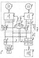
- FIG. 2 illustrates a detailed block diagram of a vehicle 100 in accordance another exemplary embodiment of the present disclosure.
- the vehicle 100 includes an onboard energy storage device 102 which may be a battery or battery back with suitable current and/or power output.
- the onboard energy storage device 102 is electrically coupled to an ES switch 104 which can be switched on and off according to switching signals 166 transmitted from a vehicle controller 152.
- the ES switch 104 can be manually switched on and off by an operator.
- the vehicle 100 further includes an onboard power conversion device 136 which may be electrically coupled to a utility power grid 132.
- the utility power grid 132 when the utility power grid 132 is available for supplying electrical power, the utility power grid 132 may provide AC electrical power 134 (e.g., 220V or 380V electrical power depending on local grid standard) to the onboard power conversion device 136.
- the onboard power conversion device 136 may include an AC-to-DC conversion device (e.g., rectifier) which is configured for converting the AC electrical power 134 according to control signals 162 transmitted from the vehicle controller 152 and provide DC electrical power with suitable voltage and/or power.
- the DC electrical power is supplied to a DC bus 122 for further delivery to various components of the vehicle 100.
- the vehicle 100 further include a drive system 30 which can be supplied with electrical power from the onboard energy storage device 102 and/or the onboard power conversion device 136.
- the drive system 30 may include a traction drive system or TM branch as indicated by reference numeral 124 in FIG. 1 .
- the traction drive system or the TM branch 124 is arranged for providing necessary mechanical output for driving motion of the vehicle 100.
- the TM branch 124 includes a TM switch 108, a TM bus 112, a TM converter 114, and a traction motor 118.
- the TM switch 108 is electrically coupled between the DC bus 122 and the TM bus 112.
- the TM switch 108 can be opened or closed according to switching signals 164 transmitted from the vehicle controller 152, such that energy/power transfer link between the DC bus 122 and the TM branch 124 can be established or terminated.
- the energy flow between the DC bus 122 and the TM branch 124 can be unidirectional or bidirectional.
- the TM converter 114 is electrically coupled between the TM bus 112 and the traction motor 118.
- the TM converter 114 is configured to perform power conversion by converting DC electrical power received from the TM bus 112 to an output power 116 with suitable form for use by the traction motor 118.
- the TM converter 114 may comprise an inverter such as a DC-AC inverter which is capable of converting the DC electrical power at the TM bus 112 to AC electrical power 116 (e.g., three-phase AC electrical power).
- the AC electrical power 116 can be regulated by a vehicle controller 152.
- the vehicle controller 152 in response to a traction torque command signal generated by operating an input device such as an acceleration pedal, can send control signals 154 to the TM converter 114 to cause the TM converter 114 to provide regulated AC electrical power 116 for the traction motor 118.
- the traction motor 118 e.g., AC electric motor
- the traction motor 118 may include a DC motor and correspondingly the TM converter 114 may comprise a DC-DC converter to perform DC power conversion.
- the vehicle controller 152 may include any suitable programmable circuits or devices such as a digital signal processor (DSP), a field programmable gate array (FPGA), a programmable logic controller (PLC), and an application specific integrated circuit (ASIC).
- DSP digital signal processor
- FPGA field programmable gate array
- PLC programmable logic controller
- ASIC application specific integrated circuit
- the drive system 30 may further include a power take-off (PTO) drive system or a PTO branch as indicated by reference numeral 126 in FIG. 2 .
- PTO power take-off
- the drive system 30 may include a plurality of PTO branches which may be configured in parallel with each other.
- the PTO drive system or the PTO branch 126 is arranged for providing necessary mechanical power output for example torque output, for performing one or more specific tasks in association with the vehicle 100. Examples of the specific tasks may include mowing plants, plowing grounds, lifting materials, shoveling materials, excavating materials, and dumping materials.
- the PTO drive system or the PTO branch 126 may include a PTO switch 138, a PTO bus 142, a PTO converter 144, and a PTO motor 148.
- the PTO switch 138 is electrically coupled between the DC bus 122 and the PTO bus 142.
- the PTO switch 138 can be switched on or off according to PTO switching signals 162 transmitted from the vehicle controller 152, such that an energy/power transfer link between the DC bus 122 and the PTO branch 126 can be established or terminated.
- the energy flow between the DC bus 122 and the PTO branch 126 can be unidirectional and bidirectional.
- the PTO converter 144 is electrically coupled between the TM bus 142 and the PTO motor 148.
- the PTO converter 144 is configured to perform power conversion by converting DC electrical power received at PTO bus 142 to a PTO output 146 having a suitable form for use by the PTO motor 148.
- the PTO converter 144 may comprise a PTO DC-AC converter or PTO inverter which is capable of converting DC electrical power received at the PTO bus 142 to AC electrical power 146 (e.g., three-phase AC electrical power).
- the AC electrical power 146 can be regulated by the vehicle controller 152.
- the vehicle controller 152 in response to a PTO torque command signal generated by operating an input device installed with the vehicle 100, can send control signals 156 to the PTO converter 144 to cause the PTO converter 144 to provide regulated AC electrical power 146 for the PTO motor 148.
- the PTO motor 148 can operate according to the AC electrical power 146 to provide desired torque output for performing one or more specific tasks in association with the vehicle 100.
- the PTO motor 148 may include a DC motor and correspondingly the PTO converter 144 may comprise a DC-DC converter to perform DC power conversion.
- the PTO motor 148 may be associated with one or more hydraulic pump systems for performing the tasks of lifting and transporting materials/cargoes.
- the vehicle 100 shown in FIG. 2 can be configured or programmed to operate with a plurality of modes, such as separate control mode, series hybrid control mode, and combined charging and operation mode. Detailed description of these operations mode will be described later with reference to flow chart diagram of FIGS. 9-13 . Before describing the flow chart diagrams, various structural embodiments of the vehicle are described with reference to FIGS. 3-8 .
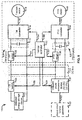
- FIG. 3 illustrates a detailed block diagram of a vehicle 110 in accordance with another exemplary embodiment of the present disclosure.
- the overall structure of the vehicle 110 and the operation thereof is substantially similar to the vehicle 100 that has been described with reference to FIG. 2 .
- the onboard power conversion device 137 is electrically coupled to a portable electricity generator 133.
- the portable electricity generator 133 may run on diesel fuel, gasoline, or other suitable material.
- the onboard power conversion device 137 can be electrically coupled to the portable electricity generator 133 and receive the electrical power 135 (e.g., AC electrical power) from the portable electricity generator 133 and convert the received electrical power 135 to suitable form for use by various components of the vehicle 110.
- the electrical power 135 e.g., AC electrical power
- the onboard power conversion system 137 may comprise an AC-DC conversion device which is capable of converting AC electrical power 135 to DC electrical power supplied to a DC bus 122.
- the electrical power output from the onboard power conversion device 137 can be regulated according to control signals 163 transmitted from the vehicle controller 152.
- the vehicle 110 shown in FIG. 3 can also be configured to operate with a plurality of modes, such as separation control mode, series hybrid control mode, and combined charging and operation control mode, which will be described in more detail below with reference to the flow chart diagrams of FIGS. 9-13 .
- FIG. 4 illustrates a detailed block diagram of a vehicle 120 in accordance with another exemplary embodiment of the present disclosure.
- the overall structure of the vehicle 120 shown in FIG. 4 and the operations thereof is substantially similar to the vehicle 100 shown and described with reference to FIG. 2 .
- an onboard power conversion device 176 is electrically coupled to a solar panel device 172.
- the solar panel device 172 is one type of a renewable power generation device which is designed for converting solar or light irradiation energy into electrical energy for direct consumption by household or transmission and distribution by a power grid.
- the solar panel device 172 is arranged as a standalone device which is located separate with respect to the vehicle 120.
- the solar panel device 172 may be integrated with the vehicle 120.
- the onboard power conversion device 176 can be configured to receive electrical power 174 provided from the solar panel device 172 and convert the electrical power 174 to an electrical power with suitable voltage and/or power for delivering to various components of the vehicle 120.
- the onboard power conversion device 176 may include a DC-DC converter which is configured to perform DC-DC power conversion to provide DC electrical power with suitable voltage and/or power.
- the DC electrical power provided from the DC-DC converter 176 can be regulated according to control signals 165 transmitted from the vehicle controller 152.
- the vehicle 120 shown in FIG. 4 can also be configured to operate with a plurality of modes, such as separation control mode, series hybrid control mode, and combined charging and operation control mode, which will be described in more detail below with reference to the flow chart diagrams of FIGS. 9-13 .
- FIG. 5 illustrates a detailed block diagram of a vehicle 140 in accordance with another exemplary embodiment of the present disclosure.
- the overall structure of the vehicle 140 shown in FIG. 5 and the operations thereof are substantially similar to the vehicle 100 shown and described with reference to FIG. 2 .
- the onboard power conversion device 186 can be electrically coupled to a wind turbine generator 182.
- a wind turbine generator 182 is another form of renewable power generation device that is designed for converting kinetic energy of wind into electrical energy for grid transmission and/or distribution.
- multiple wind turbine generators 182 may be grouped together as a wind farm for providing greater power output.
- one or more wind turbine generators 182 may be integrated with the vehicle 140.
- one or more wind turbine generators 182 may be separately arranged with respect to the vehicle 140.
- the onboard power conversion device 186 can be electrically coupled to the wind turbine generator 182 and receive the electrical power 184 therefrom.
- the electrical power 184 provided from the wind turbine generator 182 may be AC power with suitable voltage and/or power.
- the onboard power conversion device 186 may comprise an AC-DC converter functioning to convert the AC electrical power 184 to DC power with suitable voltage and/or power to be supplied to the DC bus 122.
- the wind turbine generator 182 may be configured to provide DC power with suitable voltage and/or power 184.
- the onboard power conversion device 186 may additionally or alternatively comprise a DC-DC converter 186 functioning to convert first DC power 184 to second DC power with suitable voltage and/or power to be supplied to the DC bus 122.
- the output of the onboard power conversion device 186 can be regulated or adjusted according to control signals 167 transmitted from the vehicle controller 152.
- the vehicle 140 shown in FIG. 5 can also be configured to operate with a plurality of modes, such as separation control mode, series hybrid control mode, and combined charging and operation control mode, which will be described in more detail below with reference to the flow chart diagrams of FIGS. 9-13 .
- FIG. 6 illustrates a detailed block diagram of a vehicle 150 in accordance with another exemplary embodiment of the present disclosure.
- the overall structure and detailed operations of the vehicle 150 show in FIG. 6 is substantially similar to what has been described above with reference to FIGS. 1-5 .
- One difference of the vehicle 150 shown in FIG. 6 is that the vehicle 150 may be configured to be electrically coupled to a hydro-micro turbine generator 183.
- the hydro-micro turbine generator 183 is yet another form of renewable power generation device which is functioning to convert water wave energy into electrical power.
- the hydro-micro turbine generator 183 may be integrated with the vehicle 150.
- the hydro-micro turbine generator 183 may be arranged as a standalone device, that is, located remotely with respect to the vehicle 150. As shown in FIG.
- the vehicle 150 is provided with an onboard power conversion device 187 (e.g., a AC-DC converter or a DC-DC converter) for converting electrical power 185 provided from the hydro-micro turbine generator 185 to DC power with suitable voltage and/or power to be supplied to the DC bus 122.
- the DC power output from the onboard power conversion device 187 can be regulated according to control signals 169 transmitted from the vehicle controller 152.
- the vehicle 150 shown in FIG. 6 can also be configured to operate with a plurality of modes, such as separation control mode, series hybrid control mode, and combined charging and operation control mode, which will be described in more detail below with reference to the flow chart diagrams of FIGS. 9-13 .
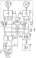
- FIG. 7 illustrates a detailed block diagram of a vehicle 160 in accordance with another exemplary embodiment of the present disclosure.
- the overall structure and detailed operations of the vehicle 160 is substantially similar to what has been described above with reference to FIGS. 1-6 .
- One difference of the vehicle 160 shown in FIG. 7 is that a converter 198 is provided in association with the onboard energy storage device 102.
- the converter 198 is illustrated being electrically coupled between the ES switch 104 and the DC bus 122.
- the converter 198 can also be electrically coupled between the onboard energy storage device 102 and the ES switch 104.
- the converter 198 may comprise a DC-DC converter which is configured to convert first DC power 103 provided from the onboard energy storage device 102 to second DC power 105 with suitable voltage and/or power to be supplied to the DC bus 122.
- the DC-DC converter 198 may comprise a unidirectional DC-DC converter for performing DC power conversion, such as boosting the voltage of the first DC power 103 to match the voltage at the DC bus 122.
- the DC-DC converter 198 may comprise a bidirectional DC-DC converter which may be useful for collecting power during regenerative or braking operations of the vehicle 160.
- the bidirectional DC-DC converter 198 can be operated to convert at least a part of the DC power at the DC bus 122 to DC power for charging the onboard energy storage device 102.
- at least part of the DC power at the DC bus 122 can be provided from the TM branch 124 by operating the traction motor 118 as a generator, which converts motion energy of the vehicle 160 into electrical power.
- the DC power at the DC bus 122 can also be provided from the PTO branch 126.
- the PTO motor 148 can be operated as a generator which converts gravitational potential energy of a load into electrical power.
- the converter 198 can be operated according to control signals 168 transmitted from the vehicle controller 152 to provide desired DC power for the DC bus 122 or desired DC power for the onboard energy storage device 102.
- the onboard power conversion device 196 is electrically coupled to an external power source 192 for receiving electrical power 194 provided therefrom.
- the external power source 192 can be any one of the power sources described above with reference to FIGS. 2-5 .
- electrical power obtained from the external power source 192 can be provided to the TM branch 124 and/or the PTO branch 126 in coordination with the onboard energy storage device 102.
- the vehicle 160 shown in FIG. 7 can also be configured to operate with a plurality of modes, such as separation control mode, series hybrid control mode, and combined charging and operation control mode, which will be described in more detail below with reference to the flow chart diagrams of FIGS. 8-10 .
- FIG. 8 illustrates a detailed block diagram of a vehicle 180 in accordance with yet another exemplary embodiment of the present disclosure.
- the vehicle 180 can optionally include a unidirectional or bidirectional DC-DC converter 198 electrically coupled between the onboard energy storage device 102 and the DC bus 122.
- the vehicle 180 may be further provided with an onboard energy storage protection function.
- the vehicle 180 may include a sensor 197 which is electrically coupled to the output of the onboard energy storage device 102 for detecting one or more electrical parameters in association with the onboard energy storage device 102.
- a sensor 197 which is electrically coupled to the output of the onboard energy storage device 102 for detecting one or more electrical parameters in association with the onboard energy storage device 102.
- a current detector is used as the sensor 197 for detecting charging and/or discharging current in association with the operation of the onboard energy storage device 102.
- other sensors or transducers may be used, including but not limited to, voltage sensors and/or thermal sensors.
- the current detector 197 may transmit a current feedback signal 199 representing actual or practical current flowing into or flowing from the onboard energy storage device 102 to the vehicle controller 152.
- the vehicle controller 152 may derive a charging and/or discharging status of the onboard energy storage device 102 based at least in part on the current feedback signal 197.
- a state of charge (SOC) of a battery or a battery pack of the onboard energy storage device 102 is determined to be fully charged (e.g., a SOC value exceeding a preset value)
- the vehicle controller 152 may transmit a switching signal 166 to the ES switch 104 to open the ES switch 104 (i.e., OFF state) to stop charging the onboard energy storage device 102.
- the vehicle controller 152 may similarly transmit a switching signal 166 to the ES switch 104 to stop discharging the onboard energy storage device 102.
- the various embodiments of the vehicles 100, 110, 120, 140, 150, 160, 180 shown and described above are merely examples only to help explain the general principles of the present disclosure.
- two or more of the vehicles described above can be combined in some manner.
- the vehicle 100 shown in FIG. 2 can also be configured to have an onboard power conversion device 136 that is capable of receiving electrical power both from the utility power grid 132 and the solar panel device 172 shown in FIG. 4 .
- the vehicle 100 can be operated with electrical power concurrently provided from the external power source (either the utility power grid 132 or the solar panel device) and the onboard energy storage device 102.
- the vehicle 120 shown in FIG. 4 can be configured to have an onboard power conversion device 176 that is capable of receiving electrical power both from the solar panel device 172 and the wind turbine generator 182 shown in FIG. 5 .
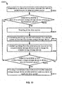
- FIGS. 9-13 illustrate flowchart diagrams of methods 3000, 4000, and 5000 for operating a vehicle and/or managing power supply of a vehicle in accordance with exemplary embodiments of the present disclosure.
- the methods 3000, 4000, and 5000 described herein can be implemented with at least some of the vehicles 100, 110, 120, 140, 150, 160, 180 shown in FIGS. 2-8 .
- the one or more blocks of methods 3000, 4000, and 5000 will be specifically described as being tied to one or more components of the vehicle 180 shown in FIG. 8 , however, the implementation of these method blocks should not be limited to the one or more components.
- FIGS. 9-13 may be programmed with software instructions stored in a computer-readable storage medium which, when executed by a processor, perform various blocks of the methods 3000, 4000, and 5000.
- the computer-readable storage medium may include volatile and nonvolatile, removable and non-removable media implemented in any method or technology.
- the computer-readable storage medium includes, but is not limited to, RAM, ROM, EEPROM, flash memory or other memory technology, CD-ROM, digital versatile disks (DVD) or other optical storage, magnetic cassettes, magnetic tape, magnetic disk storage or other magnetic storage devices, or any other non-transitory medium which can be used to store the desired information and which can accessed by a processor.
- the method 3000 generally provides a separate control operation mode for the vehicle 180 to implement.
- One benefit of providing such a separate control operation mode for the vehicle 180 is that the design of the control system of the vehicle 180 can be simplified.
- the method 3000 may start to implement from block 3002.
- an electrical connection or coupling for interconnecting the vehicle with an external power source is established.
- the electrical connection may be established by plugging one or more electrical wires or cables to an electric outlet in association with the external power source 192.
- the vehicle 180 is particularly equipped with an onboard power interface such as an onboard power conversion device 196 (e.g., AC-DC converter) for converting the electrical power 194 (e.g., AC electrical power) received from the external power source 192 to a suitable form (e.g., DC electrical power) for various components of the vehicle 180.
- an onboard power conversion device 196 e.g., AC-DC converter
- AC-DC converter AC-DC converter
- the method 3000 continues to implement by determining whether a charging mode of the vehicle is enabled. More specifically, the determining at block 3004 can be made by the vehicle controller 152 to ascertain whether a battery or a battery pack of the onboard energy storage device 102 has sufficient remaining power. If the determining by the vehicle controller 152 reveals that the onboard energy storage device 102 has low remaining power, that is, the vehicle 180 should be charged, the method 3000 then proceeds to block 3006 to implement.
- the method 3000 may proceed to block 3014 to implement, which will be described later.
- a traction drive system or a traction branch 124 shown in FIG. 8 for driving motion of the vehicle 180 is disabled.
- a PTO drive system or a PTO branch 126 shown in FIG. 8 for performing one or more specific tasks in association with the vehicle 180 is disabled.
- a TM switch 108 in the TM branch 124 and/or a TPO switch 138 in the PTO branch 126 can be opened or turned off by switching signals 164, 162 transmitted from the vehicle controller 152.
- the TM switch 108 and the PTO switch 138 can be opened or turned off in a manual manner.
- the method 3000 may continue to implement by establishing an energy transfer link between the external power source and the onboard energy storage device.
- the establishment of the energy transfer link can be achieved by closing or turning on the ES switch 104 according to switching signal 168 transmitted from the vehicle controller 152.
- the ES switch 104 can also be closed or turned on by manual operation of an operator or a user such as a driver.
- the method 3000 continues to implement by transferring at least a part of the electrical energy from the external power source to the onboard energy storage device.
- the electrical power provided from the external power source 132 is first converted by the onboard power conversion device 136 such as an AC-DC converter to DC electrical power.
- the DC electrical power then is delivered through the DC bus 122 and the ES switch 104 to the onboard energy storage device 102, such that the onboard energy storage device can be charged.
- Various charging strategies may be employed for charging the onboard energy storage device 102.
- the onboard energy storage device may be charged with a constant current or a constant voltage or a combination thereof.
- the method 3000 may continue to determine whether the vehicle should be operating in a driving mode. The determining may be made by the vehicle controller 152 to ascertain whether one or more command signals for driving the vehicle 180 has been received. If the determining by the vehicle controller 152 reveals that one or more command signals has been received, that is the vehicle 180 should be operating in the driving mode, the method 3000 may proceed to block 3015 to implement, which will be described later.
- the method 3000 may return back to block 3004 for further determining whether the vehicle 180 should be operating in charging mode.
- the method 3000 may continue to implement by disabling the onboard energy storage device of the vehicle.
- the ES switch 104 is turned off or opened according to switching signal 166 transmitted from the vehicle controller 152, such that the energy transfer link between the DC bus 122 and the onboard energy storage device 102 is cut off, thereby, the onboard energy storage device 102 stops charging and/or discharging.
- the method 3000 may continue to implement by establishing at least one energy transfer link between the external power source and at least one drive system of the vehicle.
- an energy transfer link is established between the external power source 192 and a traction drive system or a TM branch 124. More specifically, a TM switch 108 is turned on or closed by a switching signal 164 transmitted from a vehicle controller 152. In another embodiment, the TM switch 108 may be turned on or closed by manual operation. In another embodiment, additionally or alternatively, another energy transfer link is established between the external power source 192 and a PTO drive system or a PTO branch 126 shown in FIG. 8 . More specifically, the establishment of the another energy transfer link may be achieved by turning on or closing the PTO switch 138 according to switching signal 162 transmitted from the vehicle controller 152. In alternative embodiment, the PTO switch 138 may be turned on or closed by manual operation.
- the electrical power provided from the external power source is first converted to a suitable form (e.g., DC power) for the DC bus 122 by the onboard power interface or the onboard power conversion device 136 (e.g., AC-DC converter). Then, the DC electrical power on the DC bus 122 is delivered through the established energy transfer link to the TM branch 124 for driving motion of the vehicle 180. In another embodiment, the DC electrical power on the DC bus 122 can be delivered through the another established energy transfer link to the PTO branch 126 for performing one or more specific tasks in association with the vehicle 180.
- a suitable form e.g., DC power
- the DC electrical power on the DC bus 122 can be delivered through the another established energy transfer link to the PTO branch 126 for performing one or more specific tasks in association with the vehicle 180.
- the onboard power interface or the onboard power conversion device 136 continues supplying electrical power to the DC bus 122 to maintain the movement of the vehicle 180 or to maintain the one or more specific tasks implementation in association with the vehicle 180.
- the benefit of using externally-supplied electrical power for driving motion of the vehicle 180 or performing one or more special task in association with vehicle 180 is that the power stored in the battery or battery pack of the onboard energy storage device 102 can be reserved for extending the overall mileage of the vehicle 180.
- the vehicle 180 may be embodied as an electric tractor.
- the electric tractor 180 can be operated with the electrical power 134 provided from the utility power grid 132 without consuming the energy stored in the battery or battery pack of the onboard energy storage device 102. After some tasks such as plowing grounds have been performed, and the external power source such as the utility power grid 132 is unavailable for supplying electrical power to maintain the driving of the vehicle 180, the vehicle 180 can quickly switch to an internal power supply mode and use electrical power obtained from the onboard energy storage device 102 to maintain the operation of the vehicle 180.
- an external power source such as a utility power grid 132
- the method 4000 generally provides a series hybrid control operation mode for the vehicle 180 to implement or operate with.
- the method 4000 contains similar blocks as those have been described with reference to FIG. 9 .
- the method 4000 contains a block 4002 similar to block 3002 for establishing an electrical connection between the vehicle and an external power source.
- the method 4000 continues to implement by determining whether an onboard energy storage device has a low remaining power.
- the determining may be made by a vehicle controller 152 to ascertain whether a state of charge (SOC) of an battery or battery pack of the onboard energy storage device 102 is equal to or below a first threshold value (may also be referred to as a low-SOC threshold value). If the determining by the vehicle controller 152 reveals that the SOC of the onboard energy storage device is equal to or below the first threshold value, that is, the onboard energy storage device 102 has low remaining power, the method 4000 may proceed to block 4005 to implement, which will be described in more detail later.
- SOC state of charge
- the method 4000 may proceed to block 4012 to implement, which will be described in more detail later.
- a traction drive system or a traction branch 124 shown in FIG. 8 for driving motion of the vehicle 180 is disabled.
- a PTO drive system or a PTO branch 126 shown in FIG. 8 for performing one or more specific tasks in association with the vehicle 180 is disabled.
- a TM switch 108 in the TM branch 124 and/or a TPO switch 138 in the PTO branch 126 can be opened or turned off by switching signals 164, 162 transmitted from the vehicle controller 152.
- the TM switch 108 and the PTO switch 138 can be opened or turned off in a manual manner.
- the method 4000 continues to implement by establishing an energy transfer link between the external power source and the onboard energy storage device. With the established energy transfer link, the method 4000 may move to block 4008 to implement, where at least a part of the electrical energy provided from the external power source is delivered to the onboard energy storage device so as to charge the energy storage device.
- Blocks 4006, 4008 are substantially similar to the blocks 3008 and 3012 that have been shown and described with reference to FIG. 9 , thus, detailed descriptions of the two blocks 4006, 4008 are omitted here.
- the method 4000 continues to implement by determining whether an onboard energy storage device of the vehicle has sufficient remaining power.
- the determining at block 4012 may be made by the vehicle controller 152 to ascertain whether the SOC of a battery or a battery pack of the onboard energy storage device 102 is equal to or above a second threshold value (may also be referred to as high-SOC threshold value). If the determination made by the vehicle controller 152 reveals that the SOC of the battery or battery pack of the onboard energy storage device 102 is equal to or above the second threshold value or the high-SOC threshold value, that is, the onboard energy storage device 102 has sufficient remaining power, the method 4000 may proceed to the block 4014 to implement, which will be described in more detail later.
- the method 4000 may proceed to block 4016 to implement, which will be described in more detail later.
- the method 4000 continues to implement by providing a combination electrical power from the onboard energy storage device and the external power source to at least one drive system.
- Implementation of the block 4014 may involve a plurality of sub-blocks.
- FIG. 11 illustrates a more detailed flowchart diagram of the block 4014 in accordance with one exemplary embodiment.
- an energy transfer link between the onboard energy storage device and a DC bus is established.
- the establishment of the energy transfer link may be achieved by turning on or closing the ES switch 104 according to switching signal 166 transmitted from the vehicle controller 152.
- electrical power is transferred from the onboard energy storage device 102 to the DC bus 122.
- Sub-block 4032 may be implemented concurrently with the sub-block 4024. At sub-block 4032, at least part of electrical power is transferred from the external power source to the DC bus. In one embodiment, as shown in FIG. 8 , an onboard power conversion device 196 is utilized for converting electrical power provided from the external power source 192 to DC electrical power, which in turn is supplied to the DC bus 122.
- the electrical power transferred from the onboard energy storage device and the external power source are combined.
- the electrical power provided from the onboard energy storage device 102 and the electrical power provided from the onboard power interface or the onboard power conversion device 196 is combined at the DC bus 122.
- At sub-block 4044 at least one electrical connection between the DC bus and a drive system is established.
- a first energy transfer link between the DC bus 122 and the TM branch 124 is established. The establishment of the first energy transfer link may be achieved by transmitting a switching signal 164 from the vehicle controller 152 to a TM switch 108, so that the TM switch 108 can be turned on or closed according to the switching signal 164.
- a second energy transfer link between the DC bus 122 and the PTO branch 126 can be established. The establishment of the second energy transfer link can be achieved by turning on or closing the PTO switch 138 according to switching signal 162 transmitted from the vehicle controller 152.
- the process continues to implement by transferring electrical power through the established energy transfer link.
- DC electrical power at the DC bus 122 can be provided to TM inverter 114 in the TM branch 124.
- the TM inverter 114 converts the received DC electrical power to AC electrical power 116 which is used by the traction motor 118 to provide mechanical output such as torque output for driving motion of the vehicle 180.
- DC electrical power at the DC bus 122 can be transferred to the PTO inverter 144 in the PTO branch 126.
- the PTO inverter 144 converts the received DC electrical power to AC electrical power 146 which is used by the PTO motor to provide mechanical outputs such as torques outputs to perform one or more specific tasks in association with the vehicle 180.
- the method 5000 generally provides a combined charging and operation control mode for the vehicle 180 to implement or operate with.
- the method 5000 contains similar blocks as those have been described with reference to FIGS. 9-10 .
- the method 5000 contains a block 5002 which is similar to blocks 3002, 4002 described above for establishing an electrical connection between the vehicle and an external power source.
- electrical power from the external power source can be concurrently provided to the onboard energy storage device and at least a drive system of the vehicle.
- concurrently providing electrical power from the external power source to the onboard energy storage device and at least one drive system may involve a plurality of actions to be performed.
- FIG. 13 illustrates various actions that may be involved in block 5004 in accordance with one exemplary embodiment of the present disclosure.
- the onboard power conversion device 196 converts the electrical power (e.g., AC electrical power from a utility power grid) into DC electrical power for supply to the DC bus 122.
- the power conversion device 196 can be controlled to operate at a constant output current mode. In the constant output current mode, the onboard power conversion device 196 supplies the DC electrical power with a constant current to the DC bus 122.
- a desired constant current value can be determined based at least in part on the power that the traction motor 118 and/or the PTO motor 148 desired to provide as well as the power that the battery or batter pack of the onboard energy storage device 102 is desired to be charged with.
- a command signals representing the desired current reference can be input to the vehicle controller 152, which in turn transmits control signals 171 to cause the onboard power conversion device 196 to provide the desired reference current output.
- the process is basically split into two parallel branches 5030 and 5040.
- the first branch 5030 at sub-block 5032, an energy transfer link between the onboard energy storage device and a DC bus is established.
- the establishment of the energy transfer link between the onboard energy storage device 102 and the DC bus 122 can be achieved by turning on or closing the ES switch 104 according to switching signal 166 transmitted from the vehicle controller 152.
- the ES switch 104 may be turned on or closed manually.
- a first part of electrical power at the DC bus 122 is transferred from the DC bus 122 to the onboard energy storage device 102.
- an energy transfer link between the DC bus and at least one drive system is established.
- a first energy transfer link between the DC bus 122 and the TM drive system or the TM branch 124 is established. More specifically, the establishment of the first energy transfer link between the DC bus 122 and the TM branch 124 can be established by turning on or closing the TM switch 108 according to the switching signal 164 transmitted from the vehicle controller 152. Alternatively, the TM switch 108 can also be turned on or closed manually.
- a second energy transfer link between the DC bus 122 and the PTO drive system or the PTO branch 126 is established. More specifically, the establishment of the second energy transfer link can be achieved by turning on or closing the PTO switch 138 according to switching signal 162 transmitted from the vehicle controller 152. Alternatively, the PTO switch 138 can also be turned on or closed manually.
- electrical power at the DC bus can be delivered through the established energy transfer link to the at least one drive system.
- at least a second part of DC electrical power at the DC bus 122 can be delivered through the first energy transfer link to the TM inverter 114 in the first branch 124.
- the TM inverter 114 converts the DC electrical power to AC electrical power for driving the traction motor 118 to provide mechanical output such as torque output to drive motion of the vehicle 180.
- at least a second part of DC electrical power at the DC bus 122 can be delivered through the second energy transfer link to the PTO converter 144 in the second branch 126.
- the PTO converter 144 converts DC electrical power to AC electrical power for driving the PTO motor 148 to provide mechanical output such as torque outputs to perform one or more specific tasks in association with the vehicle 180.
- the method 5000 continues to determine whether an onboard energy storage device is fully charged.
- the purpose of this block 5006 is to ensure a battery or a battery pack of the onboard energy storage device will not be over-charged, because the battery lifetime can be significantly reduced when the battery or battery pack of the onboard energy storage device is over-charged.
- a sensor 197 such as a current detector is used for detecting a charging current in association with the battery or battery pack of the onboard energy storage device 102.
- the charging current feedback detected with the current detector 197 can be supplied to the vehicle controller 152 for calculating or deducing a charging energy or a charging status of the battery or battery pack of the onboard energy storage device.
- determination can be made to ascertain whether the battery or battery pack of the onboard energy storage device is fully charged by comparing the calculated charging energy or charging status with a predefined value. If the determination reveals that the onboard energy storage device is fully charged, the method 5000 may proceed to block 5008 or alternatively to block 5012 to implement, which will be described in more detail later. If the determination reveals that the onboard energy storage device is not fully charged, the method 5000 may proceed to block 5014, which will be described in more detail later.
- the onboard energy storage device may be disconnected from the external power source.
- the ES switch 104 is turned off or opened according to switching signal 166 transmitted from the vehicle controller 152, such that the energy transfer link between the DC bus 122 and the onboard energy storage device 102 is cut off.
- the ES switch 104 can be turned off or opened manually for cutting off the energy transfer link.
- the block 5008 may be omitted in some implementations. In this case, the method 5000 may proceed to block 5012, particularly, electrical power from the external power source and the onboard energy storage device are combined.
- the combined electrical power may be transferred to at least one drive system such as the TM branch 124 and PTO branch 126 shown in FIG. 8 .
- the operations involve in block 5014 is substantially similar to the block 4014 shown and described above with reference to FIGS 10-11 , thus, detailed descriptions of the block 5012 is omitted herein.
- the method 5000 continues to determine whether the onboard energy storage device is over-discharged.
- the current detector 197 as shown in FIG. 8 can also be used to detect the direction of the current flowing through the energy transfer link between the onboard energy storage device 102 and the DC bus 122. More specifically, when the current is detected being flowing from the onboard energy storage device 102 to the DC bus 122, it represents that the onboard energy storage device 102 is discharging. Further, the current feedback signals 199 can be transmitted to the vehicle controller 152 to further calculate or deduce a discharging status of the onboard energy storage device 102.
- determination can be made to ascertain whether the onboard energy storage device is over-discharged by comparing the discharging status with a predefined value. If the determination reveals that the onboard energy storage device has been over-discharged, the method 5000 may proceed to block 5016 to implement, which will be described in more detail later. If the determination reveals that the onboard energy storage device hasn't been over-discharged, the method 5000 may return back to block 5004 for concurrently providing electrical power from the external power source to the onboard energy storage device and at least one drive system. In an alternative embodiment, following the negative determination at block 5014, the method 5000 may return back to block 5012 to implement, to combine the electrical power from the onboard energy storage device and the external power source.
- the method 5000 continues to implement to disconnect the onboard energy storage device with the at least one drive system. It is also beneficial to detect whether a battery or battery pack of the onboard energy storage device is over-discharging, because an over-discharged battery or battery pack also has a reduced battery lifetime.
- the disconnection is achieved by turning off or opening the ES switch 104 according to the switching signal 166 transmitted from the vehicle controller 152, such that the energy transfer link between the DC bus 122 and the onboard energy storage device 102 is cut off, thereby, the onboard energy storage device 102 cannot supply electrical power to the TM branch 124 and the PTO branch 126.
- the ES switch 104 can be turned off or opened in a manual manner.
- the method 5000 continues to implement by providing electrical power from the external power source to at least one drive system.
- the electrical power from the external power source 12 can be converted by the onboard power conversion device 196 to DC electrical power for supply to the DC bus 122.
- the electrical power at the DC bus 122 can be supplied to the TM branch 124 for driving motion of the vehicle 180.
- the electrical power at the DC bus 122 can be supplied to the PTO branch 126 for performing one or more tasks in association with the vehicle 180.
Applications Claiming Priority (1)
| Application Number | Priority Date | Filing Date | Title |
|---|---|---|---|
| CN201210358566.2A CN103660967A (zh) | 2012-09-24 | 2012-09-24 | 具有改进的能量供应机制的移动运输设备和方法 |
Publications (2)
| Publication Number | Publication Date |
|---|---|
| EP2711233A2 true EP2711233A2 (de) | 2014-03-26 |
| EP2711233A3 EP2711233A3 (de) | 2017-10-25 |
Family
ID=49301280
Family Applications (1)
| Application Number | Title | Priority Date | Filing Date |
|---|---|---|---|
| EP13185678.3A Pending EP2711233A3 (de) | 2012-09-24 | 2013-09-24 | Stromversorgungsmanagementvorrichtung und Verfahren dafür |
Country Status (5)
| Country | Link |
|---|---|
| US (2) | US10363823B2 (de) |
| EP (1) | EP2711233A3 (de) |
| JP (1) | JP6881883B2 (de) |
| CN (1) | CN103660967A (de) |
| BR (1) | BR102013023000B1 (de) |
Cited By (6)
| Publication number | Priority date | Publication date | Assignee | Title |
|---|---|---|---|---|
| CN106095057A (zh) * | 2016-06-03 | 2016-11-09 | 板牙信息科技(上海)有限公司 | 一种车载设备的多级待机方法与车载设备 |
| EP3315346A1 (de) * | 2016-10-25 | 2018-05-02 | Jürgen Posch | Arbeitsgerät mit einem elektrischen antriebsmotor |
| RU191952U1 (ru) * | 2019-01-10 | 2019-08-28 | Общество С Ограниченной Ответственностью "Инжиниринг Комплексных Систем Автомобиля-Про" (Ооо "Икса-Про") | Схема управления электрическим мини-трактором |
| CN110497800A (zh) * | 2014-06-15 | 2019-11-26 | 高效动力传动系统公司 | 具有用于车辆到电网电能集成的交流转直流逆变器系统的车辆 |
| WO2021004639A1 (en) * | 2019-07-11 | 2021-01-14 | Volvo Truck Corporation | A control unit for an electric power transmission system |
| EP4169766A4 (de) * | 2020-10-13 | 2024-01-10 | Lg Energy Solution Ltd | System und verfahren zur verhinderung des überladens einer fahrzeugbatterie |
Families Citing this family (33)
| Publication number | Priority date | Publication date | Assignee | Title |
|---|---|---|---|---|
| CN105244928A (zh) * | 2014-07-09 | 2016-01-13 | 中兴通讯股份有限公司 | 大负载终端的电源控制方法及电源控制装置 |
| CN105799543B (zh) * | 2014-12-29 | 2019-07-30 | 上海大郡动力控制技术有限公司 | 增程式电动汽车电机控制器功能的复用方法 |
| EP3353876A4 (de) * | 2015-09-25 | 2019-06-12 | Hemant Karamchand Rohera | Energieerzeugungssystem und verfahren für ein fahrzeug |
| EP3182547A1 (de) * | 2015-12-14 | 2017-06-21 | Siemens Aktiengesellschaft | Ladungssteuerungssystem |
| US20170229897A1 (en) * | 2016-02-09 | 2017-08-10 | DTA Products Inc. | Devices and methods for portable energy storage |
| US10840813B2 (en) * | 2016-06-02 | 2020-11-17 | Mitsubishi Electric Corporation | Power conversion system |
| US10500966B2 (en) * | 2016-12-01 | 2019-12-10 | Ford Global Technologies, Llc | Adaptive boost voltage for hybrid vehicle operation |
| DE102017101145A1 (de) * | 2017-01-20 | 2018-07-26 | Torqeedo Gmbh | Vorrichtung zum Bereitstellen elektrischer Energie für einen elektrischen Verbraucher und/oder zum Laden einer Batterie in einem Boot |
| US10821839B1 (en) * | 2017-02-03 | 2020-11-03 | Wrightspeed, Inc. | Power management of electrical vehicles using range extending turbines |
| JP2018133968A (ja) * | 2017-02-17 | 2018-08-23 | 極東開発工業株式会社 | 作業車両 |
| US10660256B2 (en) | 2017-06-05 | 2020-05-26 | Deere & Company | Power capacity expansion on agricultural machine |
| CN107672456A (zh) * | 2017-09-29 | 2018-02-09 | 翟笃震 | 农业拖拉太阳能机驱动系统 |
| DE202017006948U1 (de) * | 2017-10-11 | 2019-01-03 | Audi Ag | Energiebereitstellungseinrichtung zum Bereitstellen elektrischer Energie für ein Kraftfahrzeug |
| JP2019190104A (ja) * | 2018-04-24 | 2019-10-31 | ヤンマー株式会社 | 電動式作業機械 |
| US10730459B2 (en) * | 2018-05-30 | 2020-08-04 | Nissan North America, Inc. | Vehicle electronic system |
| JP6944426B2 (ja) * | 2018-09-05 | 2021-10-06 | 株式会社日立建機ティエラ | 電動式建設機械 |
| DE102018215924A1 (de) * | 2018-09-19 | 2020-03-19 | ZF Drivetech (Suzhou) Co.Ltd. | Elektrische Antriebsachse für ein Fahrzeug |
| KR20200071873A (ko) * | 2018-12-06 | 2020-06-22 | 현대자동차주식회사 | 차량의 배터리 충전 제어 방법 |
| CN109768561A (zh) * | 2018-12-17 | 2019-05-17 | 珠海格力电器股份有限公司 | 一种电动汽车控制方法及系统 |
| JP7246977B2 (ja) * | 2019-03-13 | 2023-03-28 | マクセル株式会社 | 非接触電力伝送装置、送電装置、および、受電装置 |
| DE102019005071A1 (de) * | 2019-04-27 | 2020-10-29 | Deutz Aktiengesellschaft | Schnellladestation und Verfahren zum Laden von elektrisch betriebenen Land-, Wasser-, Luftfahrzeugen und/oder Arbeitsmaschinen und/oder Batterien |
| US10857852B2 (en) * | 2019-05-01 | 2020-12-08 | GM Global Technology Operations LLC | Adaptive radiant heating for a vehicle |
| US10857853B2 (en) * | 2019-05-01 | 2020-12-08 | GM Global Technology Operations LLC | Adaptive radiant heating system and method for achieving vehicle occupant thermal comfort |
| CN111483452B (zh) * | 2020-04-13 | 2021-06-04 | 清华大学 | 混合动力系统及其控制方法 |
| US11448136B2 (en) | 2020-04-16 | 2022-09-20 | Honeywell International Inc. | Adaptive aircraft electrical power distribution system |
| CA3176121A1 (en) * | 2020-06-10 | 2021-12-16 | Epiroc Rock Drills Aktiebolag | Method and arrangements in an electric mining machine |
| US11167919B1 (en) * | 2020-09-28 | 2021-11-09 | Oshkosh Corporation | System and method for electronic power take-off controls |
| CN112875518A (zh) * | 2021-01-28 | 2021-06-01 | 三一汽车起重机械有限公司 | 一种起重机多模式插电作业的控制系统及控制方法 |
| EP4046847A1 (de) * | 2021-02-17 | 2022-08-24 | Volvo Truck Corporation | System und verfahren zur handhabung des aus- und einkuppelns zwischen einem zapfwellensystem und einem traktionssystem in einem zumindest teilweise elektrisch betriebenen fahrzeug |
| KR102512241B1 (ko) * | 2021-03-25 | 2023-03-21 | 큐비콤 (주) | 열차 위치 및 궤도 이탈 탐지 시스템 |
| CN113258662A (zh) * | 2021-06-21 | 2021-08-13 | 北京晟科网鼎网络科技有限公司 | 电动设备的能量分配方法、能量分配装置及电动装载机 |
| CN113386588A (zh) * | 2021-07-21 | 2021-09-14 | 吉林大学 | 一种用于双源无轨卡车的电-电混合动力系统 |
| US20230264585A1 (en) * | 2022-02-20 | 2023-08-24 | Teresa Abron | Charging System for Electrical Vehicles |
Family Cites Families (40)
| Publication number | Priority date | Publication date | Assignee | Title |
|---|---|---|---|---|
| JPH04315232A (ja) | 1991-04-15 | 1992-11-06 | Nec Field Service Ltd | ディスク装置及びそのファイル管理方法 |
| JP3660773B2 (ja) | 1997-01-22 | 2005-06-15 | 富士通株式会社 | 電波妨害装置 |
| JP2000059919A (ja) | 1998-08-10 | 2000-02-25 | Toyota Motor Corp | 電気自動車のバッテリ充電装置 |
| JP2001163041A (ja) | 1999-12-07 | 2001-06-19 | Sanyo Electric Co Ltd | 自動車用空調装置 |
| US6615118B2 (en) | 2001-03-27 | 2003-09-02 | General Electric Company | Hybrid energy power management system and method |
| US20060001399A1 (en) * | 2004-07-02 | 2006-01-05 | Lembit Salasoo | High temperature battery system for hybrid locomotive and offhighway vehicles |
| US7036477B1 (en) | 2004-12-28 | 2006-05-02 | Detroit Diesel Corporation | Engine run time change for battery charging issues with automatic restart system |
| US7600595B2 (en) | 2005-03-14 | 2009-10-13 | Zero Emission Systems, Inc. | Electric traction |
| JP4591304B2 (ja) | 2005-10-17 | 2010-12-01 | 株式会社豊田自動織機 | 双方向dc/acインバータ |
| JP4504940B2 (ja) | 2006-04-14 | 2010-07-14 | 日立建機株式会社 | 作業車両の状態表示装置 |
| JP5371209B2 (ja) | 2007-06-14 | 2013-12-18 | 日立建機株式会社 | 作業車両 |
| JP4894656B2 (ja) * | 2007-07-13 | 2012-03-14 | トヨタ自動車株式会社 | 車両 |
| US7911079B2 (en) * | 2007-07-31 | 2011-03-22 | Caterpillar Inc | Electrical system architecture having high voltage bus |
| US7828099B2 (en) | 2008-02-25 | 2010-11-09 | Stephen Heckeroth | Electric tractor |
| JP4315232B1 (ja) | 2008-03-17 | 2009-08-19 | トヨタ自動車株式会社 | 電動車両 |
| US20100000804A1 (en) | 2008-07-02 | 2010-01-07 | Ming-Hsiang Yeh | Solar vehicle |
| CN201254109Y (zh) * | 2008-07-15 | 2009-06-10 | 深圳先进技术研究院 | 一种场地车用电力牵引系统 |
| US8058982B2 (en) * | 2008-08-29 | 2011-11-15 | Paccar Inc | Information display systems and methods for hybrid vehicles |
| JP5319236B2 (ja) * | 2008-10-22 | 2013-10-16 | 日立建機株式会社 | 電源装置および作業機械 |
| JP5185082B2 (ja) | 2008-11-18 | 2013-04-17 | 日立建機株式会社 | 電動式油圧作業機械 |
| US8115334B2 (en) | 2009-02-18 | 2012-02-14 | General Electric Company | Electrically driven power take-off system and method of manufacturing same |
| US8004242B1 (en) | 2009-03-13 | 2011-08-23 | PH Ingenuities, LLC | System and method for managing distribution of vehicle power in a multiple battery system |
| DE102009018240A1 (de) * | 2009-04-21 | 2010-11-04 | Adensis Gmbh | Photovoltaikanlage mit Batterie und Ersatzkraftwerk |
| JP5292186B2 (ja) | 2009-05-28 | 2013-09-18 | トヨタ自動車株式会社 | 電動車両の電源システム |
| US8026632B2 (en) | 2009-07-23 | 2011-09-27 | International Truck Intellectual Property Company, Llc | System and method for exporting a vehicle on-board AC power to a second vehicle |
| WO2011014595A2 (en) | 2009-07-31 | 2011-02-03 | Thermo King Corporation | Bi-directional battery voltage converter |
| WO2011016135A1 (ja) | 2009-08-07 | 2011-02-10 | トヨタ自動車株式会社 | 電動車両の電源システム |
| CN102470769B (zh) | 2009-08-07 | 2014-08-13 | 丰田自动车株式会社 | 电动车辆的电源系统及其控制方法 |
| US8916993B2 (en) * | 2009-08-11 | 2014-12-23 | General Electric Company | System for multiple energy storage and management and method of making same |
| JP5497381B2 (ja) | 2009-09-04 | 2014-05-21 | 株式会社日本自動車部品総合研究所 | 車両 |
| FI123470B (fi) | 2009-12-28 | 2013-05-31 | Sandvik Mining & Constr Oy | Kaivosajoneuvo ja menetelmä sen energian syöttöön |
| US8583303B2 (en) * | 2010-03-04 | 2013-11-12 | General Electric Company | Electric drive vehicle, system and method |
| JP5168308B2 (ja) | 2010-04-14 | 2013-03-21 | トヨタ自動車株式会社 | 電源システムおよびそれを搭載する車両 |
| GB201007566D0 (en) | 2010-05-06 | 2010-06-23 | Agco Sa | Tractor with hybrid power system |
| JP2011245906A (ja) | 2010-05-24 | 2011-12-08 | Iseki & Co Ltd | トラクタ |
| KR101773350B1 (ko) * | 2010-09-10 | 2017-08-31 | 알리손 트랜스미션, 인크. | 하이브리드 시스템 |
| US8403101B2 (en) | 2010-09-15 | 2013-03-26 | Deere & Company | User interface for energy sources on a hybrid vehicle |
| KR20130135227A (ko) * | 2010-10-22 | 2013-12-10 | 히다치 겡키 가부시키 가이샤 | 전동식 건설 기계 |
| JP2013544064A (ja) | 2010-11-02 | 2013-12-09 | グローバル ソーラー ウォーター アンド パワー システムズ・インコーポレーテッド | グリッド接続システム及びグリッド接続方法 |
| US8606444B2 (en) * | 2010-12-29 | 2013-12-10 | Caterpillar Inc. | Machine and power system with electrical energy storage device |
-
2012
- 2012-09-24 CN CN201210358566.2A patent/CN103660967A/zh active Pending
-
2013
- 2013-09-09 BR BR102013023000-6A patent/BR102013023000B1/pt active IP Right Grant
- 2013-09-17 US US14/028,565 patent/US10363823B2/en active Active
- 2013-09-20 JP JP2013194766A patent/JP6881883B2/ja active Active
- 2013-09-24 EP EP13185678.3A patent/EP2711233A3/de active Pending
-
2019
- 2019-06-12 US US16/439,199 patent/US11225150B2/en active Active
Non-Patent Citations (1)
| Title |
|---|
| None |
Cited By (7)
| Publication number | Priority date | Publication date | Assignee | Title |
|---|---|---|---|---|
| CN110497800A (zh) * | 2014-06-15 | 2019-11-26 | 高效动力传动系统公司 | 具有用于车辆到电网电能集成的交流转直流逆变器系统的车辆 |
| CN106095057A (zh) * | 2016-06-03 | 2016-11-09 | 板牙信息科技(上海)有限公司 | 一种车载设备的多级待机方法与车载设备 |
| CN106095057B (zh) * | 2016-06-03 | 2019-02-01 | 上海新案数字科技有限公司 | 一种车载设备的多级待机方法与车载设备 |
| EP3315346A1 (de) * | 2016-10-25 | 2018-05-02 | Jürgen Posch | Arbeitsgerät mit einem elektrischen antriebsmotor |
| RU191952U1 (ru) * | 2019-01-10 | 2019-08-28 | Общество С Ограниченной Ответственностью "Инжиниринг Комплексных Систем Автомобиля-Про" (Ооо "Икса-Про") | Схема управления электрическим мини-трактором |
| WO2021004639A1 (en) * | 2019-07-11 | 2021-01-14 | Volvo Truck Corporation | A control unit for an electric power transmission system |
| EP4169766A4 (de) * | 2020-10-13 | 2024-01-10 | Lg Energy Solution Ltd | System und verfahren zur verhinderung des überladens einer fahrzeugbatterie |
Also Published As
| Publication number | Publication date |
|---|---|
| BR102013023000B1 (pt) | 2021-06-08 |
| US20140084679A1 (en) | 2014-03-27 |
| CN103660967A (zh) | 2014-03-26 |
| US20190291594A1 (en) | 2019-09-26 |
| US10363823B2 (en) | 2019-07-30 |
| JP6881883B2 (ja) | 2021-06-02 |
| JP2014075966A (ja) | 2014-04-24 |
| EP2711233A3 (de) | 2017-10-25 |
| BR102013023000A2 (pt) | 2016-05-24 |
| US11225150B2 (en) | 2022-01-18 |
Similar Documents
| Publication | Publication Date | Title |
|---|---|---|
| US11225150B2 (en) | Power supply management apparatus and method thereof | |
| JP6553133B2 (ja) | 電気自動車を充電する装置および方法 | |
| US9216655B2 (en) | Vehicle and power supply system | |
| US8829722B2 (en) | Apparatus and method for rapidly charging an electric vehicle | |
| CN104139709B (zh) | 一种燃料电池增程器的控制系统及控制方法 | |
| US8994327B2 (en) | Apparatus and method for charging an electric vehicle | |
| US9614399B2 (en) | Charging control device using in-vehicle solar cell | |
| US10093196B2 (en) | Electric storage device, equipment, and control method | |
| US7687934B2 (en) | System and method for managing energy use in an electric vehicle | |
| US20150002056A1 (en) | Vehicle, system and method | |
| US20100198440A1 (en) | Vehicle and method of charging vehicle | |
| US9315105B2 (en) | Electrically-driven vehicle and method for controlling the same | |
| CN103221246A (zh) | 车辆的充电装置 | |
| US9415768B2 (en) | Control device for hybrid vehicle | |
| US9758091B2 (en) | Vehicle system and method for activating hazard lights during battery disconnect events | |
| EP2853459A2 (de) | Vorrichtung, Fahrzeug und Verfahren zum Betrieb von Fahrzeugen | |
| US20140103883A1 (en) | Power supply device of vehicle | |
| US20220063423A1 (en) | An electric power transmission system for a vehicle | |
| KR101304192B1 (ko) | 전기자동차 긴급 구난용 차량의 충전시스템 | |
| US10158246B2 (en) | Energy storage device, transport apparatus, and control method | |
| US20150225000A1 (en) | Propulsion control device of hybrid vehicle | |
| US9156370B1 (en) | Offboard power supply system having emission level evaluation for an electric vehicle | |
| WO2016068780A1 (en) | Method and system for switching from a first power supply path to a second power supply path |
Legal Events
| Date | Code | Title | Description |
|---|---|---|---|
| PUAI | Public reference made under article 153(3) epc to a published international application that has entered the european phase |
Free format text: ORIGINAL CODE: 0009012 |
|
| AK | Designated contracting states |
Kind code of ref document: A2 Designated state(s): AL AT BE BG CH CY CZ DE DK EE ES FI FR GB GR HR HU IE IS IT LI LT LU LV MC MK MT NL NO PL PT RO RS SE SI SK SM TR |
|
| AX | Request for extension of the european patent |
Extension state: BA ME |
|
| PUAL | Search report despatched |
Free format text: ORIGINAL CODE: 0009013 |
|
| AK | Designated contracting states |
Kind code of ref document: A3 Designated state(s): AL AT BE BG CH CY CZ DE DK EE ES FI FR GB GR HR HU IE IS IT LI LT LU LV MC MK MT NL NO PL PT RO RS SE SI SK SM TR |
|
| AX | Request for extension of the european patent |
Extension state: BA ME |
|
| RIC1 | Information provided on ipc code assigned before grant |
Ipc: B60L 11/18 20060101ALI20170915BHEP Ipc: B60L 8/00 20060101ALI20170915BHEP Ipc: B60L 15/20 20060101ALI20170915BHEP Ipc: B60L 11/00 20060101AFI20170915BHEP |
|
| 17P | Request for examination filed |
Effective date: 20180425 |
|
| RBV | Designated contracting states (corrected) |
Designated state(s): AL AT BE BG CH CY CZ DE DK EE ES FI FR GB GR HR HU IE IS IT LI LT LU LV MC MK MT NL NO PL PT RO RS SE SI SK SM TR |
|
| STAA | Information on the status of an ep patent application or granted ep patent |
Free format text: STATUS: EXAMINATION IS IN PROGRESS |
|
| 17Q | First examination report despatched |
Effective date: 20190423 |
|
| STAA | Information on the status of an ep patent application or granted ep patent |
Free format text: STATUS: EXAMINATION IS IN PROGRESS |
|
| STAA | Information on the status of an ep patent application or granted ep patent |
Free format text: STATUS: EXAMINATION IS IN PROGRESS |