EP2709774B2 - Vorrichtung zum vorwaschen zerkleinerter kunststoffteile - Google Patents
Vorrichtung zum vorwaschen zerkleinerter kunststoffteile Download PDFInfo
- Publication number
- EP2709774B2 EP2709774B2 EP12810043.5A EP12810043A EP2709774B2 EP 2709774 B2 EP2709774 B2 EP 2709774B2 EP 12810043 A EP12810043 A EP 12810043A EP 2709774 B2 EP2709774 B2 EP 2709774B2
- Authority
- EP
- European Patent Office
- Prior art keywords
- washing
- chamber
- region
- water
- removal
- Prior art date
- Legal status (The legal status is an assumption and is not a legal conclusion. Google has not performed a legal analysis and makes no representation as to the accuracy of the status listed.)
- Active
Links
Images


Classifications
-
- B—PERFORMING OPERATIONS; TRANSPORTING
- B03—SEPARATION OF SOLID MATERIALS USING LIQUIDS OR USING PNEUMATIC TABLES OR JIGS; MAGNETIC OR ELECTROSTATIC SEPARATION OF SOLID MATERIALS FROM SOLID MATERIALS OR FLUIDS; SEPARATION BY HIGH-VOLTAGE ELECTRIC FIELDS
- B03B—SEPARATING SOLID MATERIALS USING LIQUIDS OR USING PNEUMATIC TABLES OR JIGS
- B03B5/00—Washing granular, powdered or lumpy materials; Wet separating
- B03B5/28—Washing granular, powdered or lumpy materials; Wet separating by sink-float separation
-
- B—PERFORMING OPERATIONS; TRANSPORTING
- B03—SEPARATION OF SOLID MATERIALS USING LIQUIDS OR USING PNEUMATIC TABLES OR JIGS; MAGNETIC OR ELECTROSTATIC SEPARATION OF SOLID MATERIALS FROM SOLID MATERIALS OR FLUIDS; SEPARATION BY HIGH-VOLTAGE ELECTRIC FIELDS
- B03B—SEPARATING SOLID MATERIALS USING LIQUIDS OR USING PNEUMATIC TABLES OR JIGS
- B03B5/00—Washing granular, powdered or lumpy materials; Wet separating
-
- B—PERFORMING OPERATIONS; TRANSPORTING
- B03—SEPARATION OF SOLID MATERIALS USING LIQUIDS OR USING PNEUMATIC TABLES OR JIGS; MAGNETIC OR ELECTROSTATIC SEPARATION OF SOLID MATERIALS FROM SOLID MATERIALS OR FLUIDS; SEPARATION BY HIGH-VOLTAGE ELECTRIC FIELDS
- B03B—SEPARATING SOLID MATERIALS USING LIQUIDS OR USING PNEUMATIC TABLES OR JIGS
- B03B11/00—Feed or discharge devices integral with washing or wet-separating equipment
-
- B—PERFORMING OPERATIONS; TRANSPORTING
- B03—SEPARATION OF SOLID MATERIALS USING LIQUIDS OR USING PNEUMATIC TABLES OR JIGS; MAGNETIC OR ELECTROSTATIC SEPARATION OF SOLID MATERIALS FROM SOLID MATERIALS OR FLUIDS; SEPARATION BY HIGH-VOLTAGE ELECTRIC FIELDS
- B03B—SEPARATING SOLID MATERIALS USING LIQUIDS OR USING PNEUMATIC TABLES OR JIGS
- B03B5/00—Washing granular, powdered or lumpy materials; Wet separating
- B03B5/28—Washing granular, powdered or lumpy materials; Wet separating by sink-float separation
- B03B5/30—Washing granular, powdered or lumpy materials; Wet separating by sink-float separation using heavy liquids or suspensions
- B03B5/36—Devices therefor, other than using centrifugal force
- B03B5/40—Devices therefor, other than using centrifugal force of trough type
-
- B—PERFORMING OPERATIONS; TRANSPORTING
- B08—CLEANING
- B08B—CLEANING IN GENERAL; PREVENTION OF FOULING IN GENERAL
- B08B3/00—Cleaning by methods involving the use or presence of liquid or steam
- B08B3/04—Cleaning involving contact with liquid
- B08B3/041—Cleaning travelling work
- B08B3/042—Cleaning travelling work the loose articles or bulk material travelling gradually through a drum or other container, e.g. by helix or gravity
-
- B—PERFORMING OPERATIONS; TRANSPORTING
- B08—CLEANING
- B08B—CLEANING IN GENERAL; PREVENTION OF FOULING IN GENERAL
- B08B3/00—Cleaning by methods involving the use or presence of liquid or steam
- B08B3/04—Cleaning involving contact with liquid
- B08B3/10—Cleaning involving contact with liquid with additional treatment of the liquid or of the object being cleaned, e.g. by heat, by electricity or by vibration
-
- B—PERFORMING OPERATIONS; TRANSPORTING
- B03—SEPARATION OF SOLID MATERIALS USING LIQUIDS OR USING PNEUMATIC TABLES OR JIGS; MAGNETIC OR ELECTROSTATIC SEPARATION OF SOLID MATERIALS FROM SOLID MATERIALS OR FLUIDS; SEPARATION BY HIGH-VOLTAGE ELECTRIC FIELDS
- B03B—SEPARATING SOLID MATERIALS USING LIQUIDS OR USING PNEUMATIC TABLES OR JIGS
- B03B11/00—Feed or discharge devices integral with washing or wet-separating equipment
- B03B2011/008—Screw dischargers
-
- Y—GENERAL TAGGING OF NEW TECHNOLOGICAL DEVELOPMENTS; GENERAL TAGGING OF CROSS-SECTIONAL TECHNOLOGIES SPANNING OVER SEVERAL SECTIONS OF THE IPC; TECHNICAL SUBJECTS COVERED BY FORMER USPC CROSS-REFERENCE ART COLLECTIONS [XRACs] AND DIGESTS
- Y02—TECHNOLOGIES OR APPLICATIONS FOR MITIGATION OR ADAPTATION AGAINST CLIMATE CHANGE
- Y02W—CLIMATE CHANGE MITIGATION TECHNOLOGIES RELATED TO WASTEWATER TREATMENT OR WASTE MANAGEMENT
- Y02W30/00—Technologies for solid waste management
- Y02W30/50—Reuse, recycling or recovery technologies
- Y02W30/62—Plastics recycling; Rubber recycling
Definitions
- the invention relates to a device for pre-washing shredded plastic parts and for separating heavy materials or mineral components such as sand, silt, etc. from the shredded plastic parts.
- pre-washing unit that has the basic function of a heavy matter separator as protection for subsequent mechanical engineering components such as cutting mills, friction washers, mechanical dryers, etc.
- prewash unit is used to prewash comminuted plastic parts, with essentially mineral components such as sand or silt being washed off the plastic parts. It is a combined device with the function of a heavy material separator and a pre-washer.
- Devices of the generic type are known from practice which either only work as a heavy material separator or perform the task of a pre-washer. Both tasks are regularly only insufficiently achieved in the same device.
- the devices known from practice are complex and therefore expensive.
- the present invention is therefore based on the object of specifying a device for prewashing shredded plastic parts and for separating heavy materials, which in combination fulfills both tasks, is of simple construction and, not least because of the simple construction, works without problems.
- the device according to the invention comprises a material feed for the plastic parts to be prewashed, a separation area for the heavy materials, which includes a separation chamber filled with water during operation, a washing area for further washing of the floating fraction coming from the separation area, which includes a washing chamber working with shower I-spray, and an extraction area for the material washed in the washing area, which comprises a extraction chamber which is filled with water during operation.
- the shredded plastic parts are brought into the separation chamber via the material feed, preferably by gravity, and pass through a first conveyor device as a floating fraction into the washing chamber.
- the plastic parts are conveyed into the extraction chamber and from there reach a material discharge via a second conveying device. From there it is conceivable that the pre-washed plastic parts fall into a container or onto a conveyor belt for conveying to a further processing station.
- the device according to the invention is equipped with the aforementioned separation area for heavy materials, which comprises a separation chamber filled with water.
- Heavy materials which if they continue to adhere to the plastic parts, can cause damage to downstream processing units, detach themselves from the plastic parts and sink down in the water in the separation chamber, where they reach the effective area of a heavy material extractor.
- a heavy material discharge can be designed in the form of a screw arranged in the lower region of the separation chamber, so that the sedimented heavy material can be conveyed away.
- a container or receptacle with a drainage device can be installed in the heavy goods discharge.
- the sedimented heavy cargo can also be disposed of by this measure.
- the separation chamber can be equipped with an agitator protruding downwards into the separation chamber and / or with an air injection and / or water injection, so that the good material always returns to the surface received further funding.
- the first conveying device advantageously extends from the separation chamber into the washing area or into the washing chamber, the washing area adjoining the separation area.
- the first conveyor device extends up to or into the discharge area or into the discharge chamber, so that the first conveyor device serves to convey the swimming fraction completely through the washing area and thus also through the washing chamber.
- the first conveyor device can comprise at least one, preferably two conveyor screws, the two conveyor screws being arranged parallel to one another and preferably extending horizontally.
- the floating fraction i.e. the shredded plastic parts
- the two screw conveyors are conveyed into and through the washing area by the two screw conveyors.
- a screw trough designed as a sieve area can be provided, which serves to drain off washing water.
- the wash water will Provided via washing nozzles, which are used to spray or wash the swimming fraction conveyed there, the actual pre-wash thus takes place in the washing area or in the washing chamber.
- a collecting chamber for collecting the drained washing water is arranged below the washing area, preferably below the sieve area.
- the collecting chamber is dimensioned in such a way that it can hold a sufficiently large amount of washing water over a certain period of time, which continuously accumulates via the washing nozzles.
- the collecting chamber is designed as a sediment separator, the clear flow of the collecting chamber being flow-connected to a pump chamber. In this way, the clear run-off reaches the pump chamber from the wash chamber and is pumped from there to the wash nozzles so that the wash water circulates.
- a suction device for the sediment is provided in a further advantageous manner or a corresponding suction device acts, which can operate discontinuously.
- the sediment of sand or silt is thus withdrawn from the collecting chamber, preferably discontinuously.
- the material is continuously conveyed further via the first conveying device, namely into the discharge chamber. Like the separation chamber, this is filled with water.
- a second conveyor device is provided there, which - like the first conveyor device - can comprise a screw conveyor. If such a screw conveyor is provided, it is advantageous to position it between the two screw conveyors of the first conveyor device that end there, at an angle that conveys the material out of the plane of the various areas / chambers, regularly obliquely upwards or obliquely upwards and away to the side.
- the screw conveyor extends to a material discharge, which can be designed in the form of a shaft.
- air and / or water injections can be provided in the extraction chamber so that the material that is whirled up easily reaches the effective area of the second conveyor or the screw conveyor.
- a suction device for the sediment can be provided or act there.
- Such a suction device can also work discontinuously and suck off the sediment, for example via a material lock.
- the device according to the invention is characterized by the combination of a heavy material separator with effective material washing, the material washing being able to take place in a flowing water stream.
- a water treatment with circulation of the water is provided or integrated, which makes a not inconsiderable contribution to environmental protection.
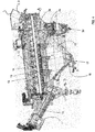
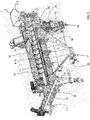
- FIGS. 1 to 5 show in schematic views an embodiment of a device according to the invention for prewashing comminuted plastic parts and for separating heavy materials or mineral components such as sand, silt, etc. from the plastic parts.
- the plastic parts are fed to the device via a material feed 1. From there, the parts pass into a separation area 2 for the heavy materials, which comprises a separation chamber 3 which is filled with water during operation.
- an agitator 3a and an air injection 3b and / or a water injection are provided in order to counteract the sinking of good material.
- a flap 3c is provided, which holds back the material sinking in the separating area 2 or in the separating chamber 3 before it gets into the heavy material extractor 3d below.
- This precaution is of particular advantage, namely to prevent incorrect discharge of floating parts by the heavy goods discharge 3d.
- a time control can be provided in a further advantageous manner that opens the flap briefly so that the sediment moves into the heavy goods outlet 3d. Then the flap 3c is closed again - automatically or manually.
- the flap 3c makes it possible to channel plastics through the device, which usually sink in the water and - without the flap being provided - are lost for recycling, namely in conventional heavy matter separators.
- the device also has a washing area 4 for further washing of the swimming fraction coming from the separation area 2.
- the washing area 4 comprises a washing chamber 6 that works with shower / spray water. If a water bath is provided, this is also located in the washing chamber 6.
- the washing area 4 is followed by a withdrawal area 7 for the good material washed in the washing area 4.
- the vent area 7 comprises a vent chamber 8 which is filled with water during operation.
- the shredded plastic parts reach the separation chamber 3 via the material feed 1 by gravity. From there, a first conveyor 9 extends through the washing area 4, so that the floating fraction from the separation area 2 into the washing area 4 and from there as good material into the extraction chamber 8 is promoted. In the extraction area 7 or in the extraction chamber 8, a second conveying device 10 is provided, which conveys the prewashed goods to a material discharge 11.
- the first conveyor device 9 comprises a conveyor screw 12, more precisely two conveyor screws 12, which run horizontally parallel to one another.
- the two screw conveyors 12 ideally convey the parts from the separation area 2 through the washing area 4 to the extraction area 7 or the extraction chamber 8.
- washing nozzles 13 are designed in the washing area 4 for spraying or washing the swimming fraction conveyed there.
- the washing water falls with the dirt loosened from the parts onto a screw trough 14 designed as a sieve area, which serves to drain off the washing water.
- a collecting chamber 15 is provided below the washing area 4, preferably below the sieve area or screw trough 14, for collecting the drained washing water, the collecting chamber 15 being designed as a sediment separator.
- the clear flow 16 of the collecting chamber 15 is flow-connected to a pump chamber from which the clear flow 16 is conveyed to the washing nozzles 13 as washing water.
- an outlet 17 is provided for the sediment.
- a suction device could be provided for the sediment, such a suction device preferably being able to work discontinuously.
- the figures also indicate that the screw conveyors 12 of the first conveying device 9 extend into the discharge chamber 8.
- the second conveyor 10 begins there, the conveyor screw 18 of which begins in the area between the two conveyor screws 12 of the first conveyor 9 and from there conveys the prewashed material to an area outside the device, namely up to the material discharge 11, so that the material there For example, can fall from the device onto a conveyor belt, not shown in the figure, or into a container.
Landscapes
- Separation Of Solids By Using Liquids Or Pneumatic Power (AREA)
- Treatment Of Sludge (AREA)
- Cleaning By Liquid Or Steam (AREA)
Description
- Die Erfindung betrifft eine Vorrichtung zum Vorwaschen zerkleinerter Kunststoffteile und zum Abscheiden von Schwerstoffen bzw. mineralischen Bestandteilen wie Sand, Schluff, etc. von den zerkleinerten Kunststoffteilen.
- Es geht hier grundsätzlich um eine Vorwascheinheit, die die grundsätzliche Funktion eines Schwerstoffabscheiders als Schutz nachfolgender maschinenbaulicher Komponenten wie beispielsweise Schneidmühle, Friktionswäscher, mechanischer Trockner, etc. hat. Außerdem dient die Vorwascheinheit zum Vorwaschen von zerkleinerten Kunststoffteilen, wobei im Wesentlichen mineralische Bestandteile wie beispielsweise Sand oder Schluff von den Kunststoffteilen abgewaschen werden. Es handelt sich hier um eine kombinierte Vorrichtung mit der Funktion eines Schwerstoffabscheiders und eines Vorwäschers.
- Aus der
DE 28 04 729 A1 ist ein Verfahren und eine entsprechende Vorrichtung zum Waschen und Trocknen zerkleinerter Kunststoffabfälle vorbekannt. Dabei werden die Kunststoffteile durch einen Behälter mit Waschflüssigkeit hindurch gefördert und dabei gewaschen. - In der
US 5,185,041 A ist eine Vorrichtung und ein entsprechendes Verfahren zum Waschen zerkleinerter Kunststoffteile offenbart. Die Kunststoffteile werden in ein sich drehendes Rohr eingegeben und dort mit Waschflüssigkeit besprüht. Das Rohr weist Ausnehmungen auf, aus denen die Waschflüssigkeit austreten kann. - Aus der Praxis sind Vorrichtungen der gattungsgemäßen Art bekannt, die entweder nur als Schwerstoffabscheider arbeiten oder die Aufgabe eines Vorwäschers erfüllen. Beide Aufgaben werden regelmäßig nur unzureichend in derselben Vorrichtung gelöst. Außerdem sind die aus der Praxis bekannten Vorrichtungen in der Konstruktion aufwändig und daher teuer.
- Der vorliegenden Erfindung liegt daher die Aufgabe zugrunde, eine Vorrichtung zum Vorwaschen zerkleinerter Kunststoffteile und zum Abscheiden von Schwerstoffen anzugeben, die in Kombination beide Aufgabe erfüllt, einfach konstruiert ist und nicht zuletzt aufgrund der einfachen Konstruktion störungsfrei arbeitet.
- Die voranstehende Aufgabe ist durch die Merkmale des Patentanspruchs 1 gelöst. Danach umfasst die erfindungsgemäße Vorrichtung eine Materialaufgabe für die vorzuwaschenden Kunststoffteile, einen Abscheidebereich für die Schwerstoffe, der eine im Betrieb mit Wasser gefüllte Abscheidekammer umfasst, einen Waschbereich zum weiteren Waschen der aus dem Abscheidebereich kommenden Schwimmfraktion, der eine mit Dusch-ISprühwasser arbeitende Waschkammer umfasst, und einen Abzugsbereich für das im Waschbereich gewaschene Gutmaterial, der eine im Betrieb mit Wasser gefüllte Abzugskammer umfasst. Die zerkleinerten Kunststoffteile werden über die Materialauf gabe vorzugsweise durch Schwerkraft in die Abscheidekammer verbracht und gelangen über eine erste Fördereinrichtung als Schwimmfraktion in die Waschkammer. Als Gutmaterial werden die Kunststoffteile in die Abzugskammer gefördert und gelangen von dort über eine zweite Fördereinrichtung zu einem Materialaustrag. Von dort aus ist es denkbar, dass die vorgewaschenen Kunststoffteile in einen Container oder auf ein Förderband zum Fördern in eine weitere Bearbeitungsstation fallen.
- Zur Abscheidung von Schwerstoffen ist die erfindungsgemäße Vorrichtung mit dem zuvor genannten Abscheidebereich für Schwerstoffe ausgestattet, der eine mit Wasser gefüllte Abscheidekammer umfasst. Schwerstoffe, die bei anhaltender Anhaftung an den Kunststoffteilen an nachfolgenden Bearbeitungsaggregaten zu Beschädigungen führen können, lösen sich von den Kunststoffteilen und sinken im Wasser der Abscheidekammer nach unten und gelangen dort in den Wirkbereich eines Schwergutabzugs. Ein solcher Schwergutabzug kann in Form einer im unteren Bereich der Abscheidekammer angeordneten Schnecke ausgeführt sein, so dass das sedimentierte Schwergut abförderbar ist. Alternativ zur Schnecke kann im Schwergutabzug ein Container bzw. ein Behältnis mit Entwässerungseinrichtung installiert sein. Auch durch diese Maßnahme lässt sich das sedimentierte Schwergut entsorgen.
- Um die Gefahr des Absinkens von Gutmaterial (zerkleinerte Kunststoffteile) zu minimieren, kann die Abscheidekammer mit einem nach unten in die Abscheidekammer ragenden Rührwerk und/oder mit einer Lufteindüsung und/oder einer Wassereindüsung ausgestattet sein, so dass das Gutmaterial immer wieder an die Oberfläche zur weiteren Förderung gelangt.
- Die erste Fördereinrichtung erstreckt sich in vorteilhafter Weise von der Abscheidekammer in den Waschbereich bzw. in die Waschkammer, wobei sich der Waschbereich an den Abscheidebereich anschließt. In ganz besonders vorteilhafter Weise erstreckt sich die erste Fördereinrichtung bis zu dem oder in den Abzugsbereich bzw. in die Abzugskammer, so dass die erste Fördereinrichtung dazu dient, die Schwimmfraktion komplett durch den Waschbereich und somit auch durch die Waschkammer hindurch zu fördern.
- Beliebige Fördereinrichtungen sind realisierbar, sofern sie geeignet sind, die oben auf schwimmende Schwimmfraktion im Wesentlichen horizontal zu fördern. In ganz besonders vorteilhafter Weise kann die erste Fördereinrichtung mindestens eine, vorzugsweise zwei Förderschnecken umfassen, wobei die beiden Förderschnecken parallel zu einander angeordnet sind und vorzugsweise horizontal verlaufen. Durch die beiden Förderschnecken wird/werden jedenfalls die Schwimmfraktion, d.h. die zerkleinerten Kunststoffteile, in und durch den Waschbereich gefördert.
- Im Waschbereich, vorzugsweise in der Waschkammer, kann ein als Siebbereich ausgeführter Schneckentrog vorgesehen sein, der zum Ablauf von Waschwasser dient. Das Waschwasser wird über Waschdüsen zur Verfügung gestellt, die zum Besprühen bzw. Waschen der dort hin geförderten Schwimmfraktion dienen die eigentliche Vorwäsche findet somit im Waschbereich bzw. in der Waschkammer statt.
- Unterhalb des Waschbereichs, vorzugsweise unterhalb des Siebbereichs, ist eine Auffangkammer zum Sammeln des abgelaufenen Waschwassers angeordnet. Die Auffangkammer ist derart dimensioniert, dass sie über einen gewissen Zeitraum hinweg eine hinreichend große Menge an Waschwasser aufnehmen kann, welches über die Waschdüsen kontinuierlich anfällt.
- In Bezug auf eine Reduktion des Wasserverbrauchs ist es von Vorteil, wenn die Auffangkammer als Sedimentabscheider ausgeführt ist, wobei der Klarlauf der Auffangkammer mit einer Pumpenkammer strömungsverbunden ist. Somit gelangt der Klarlauf aus der Waschkammer in die Pumpenkammer und wird von dort über eine Pumpe zu den Waschdüsen gefördert, so dass das Waschwasser zirkuliert.
- Im Solebereich der Auffangkammer ist in weiter vorteilhafter Weise eine Absaugeinrichtung für das Sediment vorgesehen bzw. wirkt eine entsprechende Absaugeinrichtung, wobei diese diskontinuierlich arbeiten kann. Das Sediment aus Sand oder Schluff wird somit aus der Auffangkammer vorzugsweise diskontinuierlich abgezogen.
- Vom Waschbereich bzw. von der Waschkammer aus wird das Gutmaterial über die erste Fördereinrichtung kontinuierlich weiter gefördert, nämlich in die Abzugskammer. Diese ist - wie die Abscheidekammer, mit Wasser gefüllt. Dort ist eine zweite Fördereinrichtung vorgesehen, die - wie die erste Fördereinrichtung - eine Förderschnecke umfassen kann. Bei Vorkehrung einer solchen Förderschnecke ist es von Vorteil, diese zwischen den beiden dort endenden Förderschnecken der ersten Fördereinrichtung zu positionieren, und zwar unter einem Winkel, der das Gutmaterial aus der Ebene der verschiedenen Bereiche/Kammern herausfördert, regelmäßig schräg nach oben oder schräg nach oben und zur Seite weg.
- Die Förderschnecke erstreckt sich bis zu einem Materialaustrag hin, der in Form eines Schachts ausgeführt sein kann.
- Zur Unterstützung des Materialtransports von der Abzugskammer aus zum Materialaustrag können in der Abzugskammer Lufteindüsungen und/oder Wassereindüsungen vorgesehen sein, so dass das dadurch aufgewirbelte Gutmaterial mühelos in den Wirkbereich der zweiten Fördereinrichtung bzw. der Förderschnecke gelangt.
- Im Bodenbereich der Abzugskammer bildet sich Sediment. Entsprechend kann dort eine Absaugeinrichtung für das Sediment vorgesehen sein bzw. wirken. Eine solche Absaugeinrichtung kann ebenfalls diskontinuierlich arbeiten und dabei das Sediment beispielsweise über eine Materialschleuse absaugen.
- Entsprechend den voranstehenden Ausführungen zeichnet sich die erfindungsgemäße Vorrichtung durch die Kombination eines Schwerstoffabscheiders mit effektiver Materialwäsche aus, wobei die Materialwäsche in einem fließenden Wasserstrom erfolgen kann. Zur Minimierung des Wasserverbrauchs ist eine Wasseraufbereitung mit Kreislaufführung des Wassers vorgesehen bzw. integriert, wodurch ein nicht unerheblicher Beitrag zum Umweltschutz geleistet wird.
- Es gibt nun verschiedene Möglichkeiten, die Lehre der vorliegenden Erfindung in vorteilhafter Weise auszugestalten und weiterzubilden. Dazu ist einerseits auf die dem Anspruch 1 nachgeordneten Ansprüche und andererseits auf die nachfolgende Erläuterung eines bevorzugten Ausführungsbeispiels der Erfindung anhand der Zeichnung zu verweisen. In Verbindung mit der Erläuterung des bevorzugten Ausführungsbeispiels der Erfindung anhand der Zeichnung werden auch im Allgemeinen bevorzugte Ausgestaltungen und Weiterbildungen der Lehre erläutert. In der Zeichnung zeigen
- Fig. 1
- in einer schematischen Seitenansicht, teilweise geschnitten, ein Ausführungsbeispiel einer erfindungsgemäßen Vorrichtung mit den wesentlichen Bereichen bzw. Kammern/Funktionselementen,
- Fig. 2
- in einer schematischen Seitenansicht, teilweise geschnitten, den Gegenstand aus
Fig. 1 , jedoch ohne Maschinengestell, - Fig. 3
- in einer schematischen Draufsicht den Gegenstand aus
Fig. 1 , - Fig. 4
- in einer perspektivischen Ansicht, im Bereich der vorderen Förderschnecke geschnitten, den Gegenstand aus
Fig. 1 und - Fig. 5
- in einer perspektivischen Ansicht, im Schnitt vor der hinteren Förderschnecke den Gegenstand aus
Fig. 4 . - Die
Figuren 1 bis 5 zeigen in schematischen Ansichten ein Ausführungsbeispiel einer erfindungsgemäßen Vorrichtung zum Vorwaschen zerkleinerter Kunststoffteile und zum Abscheiden von Schwerstoffen bzw. mineralischen Bestandteilen wie Sand, Schluff, etc. von den Kunststoffteilen. - Die Kunststoffteile werden über eine Materialaufgabe 1 der Vorrichtung zugeführt. Von dort aus gelangen die Teile in einen Abscheidebereich 2 für die Schwerstoffe, der eine im Betrieb mit Wasser gefüllte Abscheidekammer 3 umfasst.
- In der Abscheidekammer 3 sind ein Rührwerk 3a und eine Lufteindüsung 3b und/oder eine Wassereindüsung vorgesehen, um dem Absinken von Gutmaterial entgegenzuwirken.
- Die Figuren zeigen gemeinsam, dass unterhalb der Abscheidekammer 3, direkt unterhalb des Rührwerks 3a, eine Klappe 3c vorgesehen ist, die das im Abscheidebereich 2 bzw. in der Abscheidekammer 3 sinkende Material zurückhält, bevor es in den darunter befindlichen Schwergutabzug 3d gelangt. Diese Vorkehrung ist von besonderem Vorteil, um nämlich einen Fehlaustrag von schwimmenden Teilen durch den Schwergutabzug 3d zu verhindern. Für den Fall, dass sich auf der Klappe 3c eine Sedimentschicht aus Sand, Schmutz, etc. bildet, kann eine Zeitsteuerung in weiter vorteilhafter Weise vorgesehen sein, die die Klappe kurzzeitig öffnet, so dass sich das Sediment in den Schwergutabzug 3d bewegt. Danach wird die Klappe 3c wieder - automatisch oder manuell - geschlossen. Die Klappe 3c ermöglicht es, Kunststoffe durch die Vorrichtung zu schleusen, welche im Wasser üblicherweise absinken und - ohne Vorkehrung der Klappe -, nämlich in herkömmlichen Schwerstoffabscheidern, für das Recycling verloren gehen.
- Des Weiteren gehört zu der Vorrichtung ein Waschbereich 4 zum weiteren Waschen der aus dem Abscheidebereich 2 kommenden Schwimmfraktion. Der Waschbereich 4 umfasst eine mit Dusch-/Sprühwasser arbeitende Waschkammer 6. Bei Vorkehrung eines Wasserbads befindet sich diese ebenfalls in der Waschkammer 6.
- An den Waschbereich 4 schließt sich ein Abzugsbereich 7 für das im Waschbereich 4 gewaschene Gutmaterial an. Der Abzugsbereich 7 umfasst eine im Betrieb mit Wasser gefüllte Abzugskammer 8.
- Die zerkleinerten Kunststoffteile gelangen über die Materialaufgabe 1 durch Schwerkraft in die Abscheidekammer 3. Von dort aus erstreckt sich eine erste Fördereinrichtung 9 durch den Waschbereich 4 hindurch, so dass die Schwimmfraktion vom Abscheidebereich 2 in den Waschbereich 4 und von dort als Gutmaterial in die Abzugskammer 8 gefördert wird. Im Abzugsbereich 7 bzw. in der Abzugskammer 8 ist eine zweite Fördereinrichtung 10 vorgesehen, die das vorgewaschene Gut zu einem Materialaustrag 11 fördert.
- Die Figuren lassen erkennen, dass die erste Fördereinrichtung 9 eine Förderschnecke 12 umfasst, genauergesagt zwei Förderschnecken 12, die parallel zueinander horizontal verlaufen. Die beiden Förderschnecken 12 fördern in idealer Weise die Teile vom Abscheidebereich 2 durch den Waschbereich 4 hindurch bis in den Abzugsbereich 7 bzw. die Abzugskammer 8.
- In den Figuren ist des Weiteren angedeutet, dass im Waschbereich 4 Waschdüsen 13 zum Besprühen bzw. Waschen der dort hin geförderten Schwimmfraktion ausgebildet sind. Das Waschwasser fällt mit dem von den Teilen gelösten Schmutz auf einen als Siebbereich ausgeführten Schneckentrog 14, der zum Ablauf des Waschwassers dient.
- Unterhalb des Waschbereichs 4, vorzugsweise unterhalb des Siebbereichs bzw. Schneckentrogs 14, ist eine Auffangkammer 15 zum Sammeln des abgelaufenen Waschwassers vorgesehen, wobei die Auffangkammer 15 als Sedimentabscheider ausgeführt ist. Der Klarlauf 16 der Auffangkammer 15 ist mit einer Pumpenkammer strömungsverbunden, von der aus der Klarlauf 16 als Waschwasser zu den Waschdüsen 13 gefördert wird. Im Solenbereich der Auffangkammer 15 ist eine Ausschleußung 17 für das Sediment vorgesehen. Alternativ dazu könnte eine Absaugeinrichtung für das Sediment vorgesehen sein, wobei eine solche Absaugeinrichtung vorzugsweise diskontinuierlich arbeiten kann.
- In den Figuren ist des Weiteren angedeutet, dass die Förderschnecken 12 der ersten Fördereinrichtung 9 sich bis in die Abzugskammer 8 hinein erstrecken. Dort beginnt die zweite Fördereinrichtung 10, deren Förderschnecke 18 im Bereich zwischen den beiden Förderschnecken 12 der ersten Fördereinrichtung 9 beginnt und von dort aus das vorgewaschene Gut in einen Bereich außerhalb der Vorrichtung fördert, nämlich bis hin zu dem Materialaustrag 11, so dass dort das Gut aus der Vorrichtung beispielsweise auf ein in der Fig. nicht gezeigten Förderband oder in einen Container fallen kann.
- Hinsichtlich weiterer vorteilhafter Ausgestaltungen der erfindungsgemäßen Vorrichtung wird zur Vermeidung von Wiederholungen auf den allgemeinen Teil der Beschreibung sowie auf die beigefügten Ansprüche verwiesen.
- Schließlich sei ausdrücklich darauf hingewiesen, dass das voranstehend beschriebene Ausführungsbeispiel der erfindungsgemäßen Vorrichtung lediglich zur Erörterung der beanspruchten Lehre dient, dieses jedoch nicht auf das Ausführungsbeispiel einschränkt.
-
- 1
- Materialaufgabe
- 2
- Abscheidebereich
- 3
- Abscheidekammer
- 3a
- Rührwerk
- 3b
- Lufteindüsung
- 3c
- Klappe
- 3d
- Schwergutabzug
- 4
- Waschbereich
- 5
- Wasserbad
- 6
- Waschkammer
- 7
- Abzugsbereich
- 8
- Abzugskammer
- 9
- erste Fördereinrichtung
- 10
- zweite Fördereinrichtung
- 11
- Materialaustrag
- 12
- Förderschnecke (von 9)
- 13
- Waschdüse
- 14
- Schneckentrog
- 15
- Auffangkammer
- 16
- Klarlauf
- 17
- Ausschleußung
- 18
- Förderschnecke (von 10)
Claims (16)
- Vorrichtung zum Vorwaschen zerkleinerter Kunststoffteile und zum Abscheiden von Schwerstoffen bzw. mineralischen Bestandteilen wie Sand, Schluff, etc., mit einer Materialaufgabe (1) für die vorzuwaschenden Kunststoffteile, einem Abscheidebereich (2) für die Schwerstoffe, der eine im Betrieb wassergefüllte Abscheidekammer (3) umfasst, einem Waschbereich (4) zum weiteren Waschen der aus dem Abscheidebereich (2) kommenden Schwimmfraktion, der eine mit Dusch-/Sprühwasser arbeitende Waschkammer (6) umfasst, und einem Abzugsbereich (7) für das im Waschbereich (4) gewaschene Gutmaterial, der eine im Betrieb mit Wasser gefüllte Abzugskammer (8) umfasst, wobei die Kunststoffteile über die Materialaufgabe (1) vorzugsweise durch Schwerkraft in die Abscheidekammer (8), über eine erste Fördereinrichtung (9) als Schwimmfraktion in die Waschkammer (6) und als Gutmaterial in die Abzugskammer (8) gelangen und von dort über eine zweite Fördereinrichtung (10) zu einem Materialaustrag (11) gefördert werden.
- Vorrichtung nach Anspruch 1, dadurch gekennzeichnet, dass die Abscheidekammer (3) einen Schwergutabzug, vorzugsweise in Form einer im unteren Bereich angeordneten Schnecke, umfasst.
- Vorrichtung nach Anspruch 1, dadurch gekennzeichnet, dass die Abscheidekammer (3) einen Container mit Entwässerungseinrichtung umfasst.
- Vorrichtung nach einem der Ansprüche 1 bis 3, dadurch gekennzeichnet, dass die Abscheidekammer (3) ein vorzugsweise nach unten in die Kammer (3) hinein ragendes Rührwerk (3a) und/oder eine Lufteindüsung (3b) und/oder eine Wassereindüsung umfasst.
- Vorrichtung nach einem der Ansprüche 1 bis 4, dadurch gekennzeichnet, dass sich die erste Fördereinrichtung (9) von der Abscheidekammer (3) in den Waschbereich (4) bzw. in die Waschkammer (6) erstreckt.
- Vorrichtung nach einem der Ansprüche 1 bis 5, dadurch gekennzeichnet, dass sich die erste Fördereinrichtung (9) bis zu dem oder in den Abzugsbereich (7) bzw. in die Abzugskammer (8) erstreckt.
- Vorrichtung nach einem der Ansprüche 1 bis 6, dadurch gekennzeichnet, dass die erste Fördereinrichtung (9) mindestens eine, vorzugsweise zwei Förderschnecken (12) umfasst.
- Vorrichtung nach Anspruch 7, dadurch gekennzeichnet, dass die Förderschnecken (12) parallel zueinander angeordnet sind und vorzugsweise horizontal verlaufen.
- Vorrichtung nach einem der Ansprüche 1 bis 7, dadurch gekennzeichnet, dass im Waschbereich (4), vorzugsweise in der Waschkammer (6), ein als Siebbereich ausgeführter Schneckentrog (14) vorgesehen ist, der zum Ablauf von Waschwasser (6) dient.
- Vorrichtung nach einem der Ansprüche 1 bis 9, dadurch gekennzeichnet, dass im Waschbereich (4) Waschdüsen (13) zum Besprühen bzw. Waschen der dorthin geförderten Schwimmfraktion ausgebildet sind.
- Vorrichtung nach Anspruch 10 oder 11, dadurch gekennzeichnet, dass unterhalb des Waschbereichs (4), vorzugsweise unterhalb des Siebbereichs, eine Auffangkammer (15) zum Sammeln des abgelaufenen Waschwassers angeordnet ist.
- Vorrichtung nach Anspruch 11, dadurch gekennzeichnet, dass die Auffangkammer (15) als Sedimentabscheider ausgeführt ist, wobei der Klarlauf (16) der Auffangkammer (15) mit einer Pumpenkammer strömungsverbunden ist, von der aus der Klarlauf (16) als Waschwasser zu den Waschdüsen (13) gefördert wird.
- Vorrichtung nach Anspruch 11 oder 12, dadurch gekennzeichnet, dass im Solenbereich der Auffangkammer (15) eine Absaugeinrichtung (17) für das Sediment wirkt, wobei die Absaugeinrichtung (17) vorzugsweise diskontinuierlich arbeitet.
- Vorrichtung nach einem der Ansprüche 1 bis 13, dadurch gekennzeichnet, dass die in der Abzugskammer (8) vorgesehene zweite Fördereinrichtung (10) eine Förderschnecke (18) umfasst, die vorzugsweise zwischen den beiden dort enden Förderschnecken (12) der ersten Fördereinrichtung (9) läuft und sich zum Materialaustrag (11) erstreckt.
- Vorrichtung nach einem der Ansprüche 1 bis 14, dadurch gekennzeichnet, dass zur Unterstützung des Materialtransports in der Abzugskammer (8) Lufteindüsungen und/oder Wassereindüsungen vorgesehen sind.
- Vorrichtung nach einem der Ansprüche 1 bis 15, dadurch gekennzeichnet, dass im Bodenbereich der Abzugskammer (8) eine Ausschleußung (17) oder eine Absaugeinrichtung für das Sediment wirkt, wobei die Ausschleußung (17) oder die Absaugeinrichtung vorzugsweise diskontinuierlich arbeitet und das Sediment über eine Materialschleuse absaugt.
Priority Applications (1)
| Application Number | Priority Date | Filing Date | Title |
|---|---|---|---|
| PL12810043T PL2709774T5 (pl) | 2012-06-06 | 2012-10-10 | Urządzenie do wstępnego mycia rozdrobnionych części z tworzywa sztucznego |
Applications Claiming Priority (2)
| Application Number | Priority Date | Filing Date | Title |
|---|---|---|---|
| DE102012209574 | 2012-06-06 | ||
| PCT/DE2012/200067 WO2013182174A1 (de) | 2012-06-06 | 2012-10-10 | Vorrichtung zum vorwaschen zerkleinerter kunststoffteile |
Publications (3)
| Publication Number | Publication Date |
|---|---|
| EP2709774A1 EP2709774A1 (de) | 2014-03-26 |
| EP2709774B1 EP2709774B1 (de) | 2015-06-03 |
| EP2709774B2 true EP2709774B2 (de) | 2021-01-06 |
Family
ID=47504535
Family Applications (1)
| Application Number | Title | Priority Date | Filing Date |
|---|---|---|---|
| EP12810043.5A Active EP2709774B2 (de) | 2012-06-06 | 2012-10-10 | Vorrichtung zum vorwaschen zerkleinerter kunststoffteile |
Country Status (5)
| Country | Link |
|---|---|
| US (1) | US9486811B2 (de) |
| EP (1) | EP2709774B2 (de) |
| HU (1) | HUE025391T2 (de) |
| PL (1) | PL2709774T5 (de) |
| WO (1) | WO2013182174A1 (de) |
Families Citing this family (12)
| Publication number | Priority date | Publication date | Assignee | Title |
|---|---|---|---|---|
| CN104400935A (zh) * | 2014-11-14 | 2015-03-11 | 重庆海山橡塑化工有限公司 | 废旧塑料清洗机 |
| CN104384138A (zh) * | 2014-11-14 | 2015-03-04 | 重庆海山橡塑化工有限公司 | 废旧塑料再生清洗机 |
| PL3221058T3 (pl) * | 2014-11-21 | 2019-07-31 | Wamgroup S.P.A. | Urządzenie podające oraz instalacja do odzyskiwania resztek betonu |
| DE102015009593B4 (de) * | 2015-07-24 | 2021-05-20 | Ulrich Winkler | Vorrichtung und Verfahren zur Separation von Kunststoffmahlgut nach der spezifischen Dichte |
| DE102015012354B4 (de) | 2015-09-22 | 2017-08-31 | Lindner washTech GmbH | Vorrichtung zum Waschen von kleinstückigem Material |
| GB2548856B (en) * | 2016-03-30 | 2018-03-21 | Cde Global Ltd | Apparatus for processing aggregate material |
| FR3057789A1 (fr) * | 2016-10-21 | 2018-04-27 | Suez Groupe | Dispositif compact de recyclage de dechets plastiques |
| DE202017006034U1 (de) * | 2017-11-22 | 2019-02-25 | Doppstadt Austria Gmbh | Vorrichtung zum Trennen von Materialgemischen |
| IT202000008068A1 (it) * | 2020-04-16 | 2021-10-16 | Ecomade Eng Srl | Apparato di alimentazione e dosatura di sovvallo da rifiuto indifferenziato |
| GB2609224B (en) | 2021-07-23 | 2023-08-02 | Cde Global Ltd | Apparatus for processing aggregate material |
| CN116273430B (zh) * | 2022-11-29 | 2023-10-03 | 新疆农业科学院土壤肥料与农业节水研究所(新疆维吾尔自治区新型肥料研究中心) | 设置选果装置的干果收获机 |
| CN118082042B (zh) * | 2024-04-23 | 2024-07-05 | 南京诺达鑫业挤出装备有限公司 | 一种挤塑材料预处理设备及方法 |
Citations (8)
| Publication number | Priority date | Publication date | Assignee | Title |
|---|---|---|---|---|
| DE2803164A1 (de) † | 1977-02-08 | 1978-08-10 | Sorema Srl | Geraet zum abtrennen von kleinstueckigen stoffen |
| DE3210972A1 (de) † | 1982-03-25 | 1983-10-13 | Alu Plast Aluminium-Plastik Recycling GmbH, 5440 Mayen | Trennanlage |
| DE3210973C2 (de) † | 1982-03-25 | 1984-11-22 | Alu Plast Aluminium-Plastik Recycling GmbH, 5440 Mayen | Waschvorrichtung |
| DE3210976C2 (de) † | 1982-03-25 | 1984-11-29 | Alu Plast Aluminium-Plastik Recycling GmbH, 5440 Mayen | Waschvorrichtung und Verfahren zum Waschen von Kunststoffkleinteilen |
| DE9207306U1 (de) † | 1992-05-29 | 1992-08-06 | Häberle, Wilhelm, 72516 Scheer | Trenneinrichtung |
| DE4205767A1 (de) † | 1992-02-26 | 1993-09-02 | Joachim Kopischke | Verfahren zur trennung zerkleinerter kunststoffe verschiedener chemischer zusammensetzung und unterschiedlicher spezifischer dichte |
| DE4426608A1 (de) † | 1994-07-05 | 1996-01-11 | Irv Interroh Rohstoffverwertun | Mobile Reststoff-Bearbeitung |
| DE19642207A1 (de) † | 1996-10-12 | 1998-04-16 | Agritechnik Ing Betrieb | Anlage zur Trennung und Säuberung von Leicht- und Schwerstoffen |
Family Cites Families (21)
| Publication number | Priority date | Publication date | Assignee | Title |
|---|---|---|---|---|
| US1792179A (en) * | 1928-05-09 | 1931-02-10 | George W Wilmot | Coal-cleaning apparatus |
| US2365734A (en) * | 1939-06-30 | 1944-12-26 | Klaas F Tromp | Apparatus for separating solids in suspension medium |
| US4169787A (en) * | 1977-12-12 | 1979-10-02 | Campbell Soup Company | Apparatus and method for liquid separation of materials |
| DE2804729C2 (de) | 1978-02-01 | 1985-03-07 | Buckau-Walther AG, 4048 Grevenbroich | Vorrichtung zum Waschen und Trocknen von Schüttgut, insbesondere zerkleinerten Kunststoffabfällen |
| US4375264A (en) * | 1981-05-19 | 1983-03-01 | Doxsee Food Corp. | Method and apparatus for segregating and separately recovering solids of different densities |
| US4585547A (en) * | 1984-09-14 | 1986-04-29 | Nicholson G W | Method and apparatus for cleaning coal |
| US4750995A (en) * | 1985-01-11 | 1988-06-14 | Ore-Ida Foods, Inc. | Starch separation of potato strips |
| US4858769A (en) * | 1986-05-19 | 1989-08-22 | Devries Jeffrey S | Flotation separator |
| US4813618A (en) * | 1987-10-02 | 1989-03-21 | Cullom James P | Apparatus and method for sorting demolition debris |
| US4946584A (en) * | 1987-10-05 | 1990-08-07 | George J. Olney, Inc. | Hydraulic product separator |
| US5039534A (en) * | 1990-06-22 | 1991-08-13 | The Pillsbury Company | Pea separating apparatus and method of use |
| US5185041A (en) | 1990-12-26 | 1993-02-09 | Anderson Robert M | Machine for washing plastic fragments to prepare them for recycling |
| US5547569A (en) * | 1995-01-25 | 1996-08-20 | Hinkle Contracting Corporation | Multiple stage water clarifier |
| US6138834A (en) * | 1999-01-08 | 2000-10-31 | Sun Drilling Corporation | Recovery apparatus for drilling and excavation application and related methods |
| US6506310B2 (en) * | 2001-05-01 | 2003-01-14 | Del Corporation | System and method for separating solids from a fluid stream |
| US7017753B2 (en) * | 2003-05-13 | 2006-03-28 | Steven Tse | Apparatus and method of separating heavy materials in garbage from light ones and classifying the heavy garbage for collection |
| US7255233B2 (en) * | 2004-06-14 | 2007-08-14 | Uchicago Argonne Llc | Method and apparatus for separating mixed plastics using flotation techniques |
| US8151993B2 (en) * | 2006-11-15 | 2012-04-10 | Construction Equipment Company | Material separator systems |
| US20080135461A1 (en) * | 2006-12-06 | 2008-06-12 | Olivier Paul A | Dense medium separator |
| US7954642B2 (en) * | 2008-09-26 | 2011-06-07 | U Chicago Argonne, Llc | Process and apparatus for separating solid mixtures |
| WO2012019101A2 (en) * | 2010-08-06 | 2012-02-09 | Berry Plastics Corporation | Separation process for plastics materials |
-
2012
- 2012-10-10 US US14/398,894 patent/US9486811B2/en active Active
- 2012-10-10 PL PL12810043T patent/PL2709774T5/pl unknown
- 2012-10-10 EP EP12810043.5A patent/EP2709774B2/de active Active
- 2012-10-10 WO PCT/DE2012/200067 patent/WO2013182174A1/de not_active Ceased
- 2012-10-10 HU HUE12810043A patent/HUE025391T2/en unknown
Patent Citations (8)
| Publication number | Priority date | Publication date | Assignee | Title |
|---|---|---|---|---|
| DE2803164A1 (de) † | 1977-02-08 | 1978-08-10 | Sorema Srl | Geraet zum abtrennen von kleinstueckigen stoffen |
| DE3210972A1 (de) † | 1982-03-25 | 1983-10-13 | Alu Plast Aluminium-Plastik Recycling GmbH, 5440 Mayen | Trennanlage |
| DE3210973C2 (de) † | 1982-03-25 | 1984-11-22 | Alu Plast Aluminium-Plastik Recycling GmbH, 5440 Mayen | Waschvorrichtung |
| DE3210976C2 (de) † | 1982-03-25 | 1984-11-29 | Alu Plast Aluminium-Plastik Recycling GmbH, 5440 Mayen | Waschvorrichtung und Verfahren zum Waschen von Kunststoffkleinteilen |
| DE4205767A1 (de) † | 1992-02-26 | 1993-09-02 | Joachim Kopischke | Verfahren zur trennung zerkleinerter kunststoffe verschiedener chemischer zusammensetzung und unterschiedlicher spezifischer dichte |
| DE9207306U1 (de) † | 1992-05-29 | 1992-08-06 | Häberle, Wilhelm, 72516 Scheer | Trenneinrichtung |
| DE4426608A1 (de) † | 1994-07-05 | 1996-01-11 | Irv Interroh Rohstoffverwertun | Mobile Reststoff-Bearbeitung |
| DE19642207A1 (de) † | 1996-10-12 | 1998-04-16 | Agritechnik Ing Betrieb | Anlage zur Trennung und Säuberung von Leicht- und Schwerstoffen |
Also Published As
| Publication number | Publication date |
|---|---|
| EP2709774A1 (de) | 2014-03-26 |
| US9486811B2 (en) | 2016-11-08 |
| PL2709774T3 (pl) | 2015-11-30 |
| WO2013182174A1 (de) | 2013-12-12 |
| EP2709774B1 (de) | 2015-06-03 |
| PL2709774T5 (pl) | 2021-05-17 |
| HUE025391T2 (en) | 2016-02-29 |
| US20150114887A1 (en) | 2015-04-30 |
Similar Documents
| Publication | Publication Date | Title |
|---|---|---|
| EP2709774B1 (de) | Vorrichtung zum vorwaschen zerkleinerter kunststoffteile | |
| DE2813056A1 (de) | Trennvorrichtung zum wiedergewinnen der zuschlagstoffe aus nicht-abgebundenem beton | |
| DE3800204A1 (de) | Verfahren und vorrichtung zum sortieren von kunststoffabfaellen | |
| DE2713730A1 (de) | Verfahren und vorrichtung zum reinigen verschmutzter kunststoff-schnitzel | |
| DE2929857C2 (de) | ||
| EP2427310B2 (de) | Verfahren und vorrichtung zum aufbereiten verunreinigter kunststoffgebinde, insbesondere ölbehälter | |
| DE4023434A1 (de) | Verfahren zur separierung von kunststoffmaterialien | |
| CH629400A5 (en) | Apparatus for washing particulate, floatable products, in particular shreds of plastic sheets and strips | |
| EP3488931A1 (de) | Vorrichtung zum trennen von materialgemischen | |
| DE202010000494U1 (de) | Vorrichtung zur Aufbereitung von Pökellake | |
| DE102015012354B4 (de) | Vorrichtung zum Waschen von kleinstückigem Material | |
| WO1995019212A1 (de) | Vorrichtung zur reinigung von in abwassern enthaltenen feststoffen | |
| DE102007063510A1 (de) | Verfahren und Vorrichtung zur Aufbereitung von Kunststoffabfällen | |
| DE19805451A1 (de) | Kehrichtwascher | |
| DE102010004235B4 (de) | Vorrichtung zur Reinigung von Kunststoffteilen | |
| DE19600372C1 (de) | Vorrichtung zum Austragen von festen Verunreinigungen aus Abwasser | |
| EP3005928B1 (de) | Transportgeschirrspülmaschine | |
| DE3909058C2 (de) | Trockenbohrabsauganlage | |
| DE19715818C1 (de) | Einrichtung zur Materialtrennung für aus Glas und zumindest einem weiteren Material bestehende Gegenstände | |
| EP0401812A1 (de) | Verfahren und Vorrichtung zur Aufbereitung von Hackfrüchten | |
| WO2021121632A1 (de) | Waschen von schüttgut | |
| DE102013101892B4 (de) | Vorrichtung zur Abtrennung von an Knollenfrüchten, wie beispielsweise Zuckerrüben, anhaftendem Erdanhang und Steinen | |
| DE202019102953U1 (de) | Siebvorrichtung zum Entfernen von Feststoffen aus Abwasser | |
| DE102011018720B4 (de) | Vorrichtung und Verfahren zum Reinigen von Stückgutkästen | |
| EP3479902B1 (de) | Einrichtung zur wiederaufbereitung von restbeton |
Legal Events
| Date | Code | Title | Description |
|---|---|---|---|
| PUAI | Public reference made under article 153(3) epc to a published international application that has entered the european phase |
Free format text: ORIGINAL CODE: 0009012 |
|
| 17P | Request for examination filed |
Effective date: 20131219 |
|
| AK | Designated contracting states |
Kind code of ref document: A1 Designated state(s): AL AT BE BG CH CY CZ DE DK EE ES FI FR GB GR HR HU IE IS IT LI LT LU LV MC MK MT NL NO PL PT RO RS SE SI SK SM TR |
|
| GRAP | Despatch of communication of intention to grant a patent |
Free format text: ORIGINAL CODE: EPIDOSNIGR1 |
|
| INTG | Intention to grant announced |
Effective date: 20150116 |
|
| GRAS | Grant fee paid |
Free format text: ORIGINAL CODE: EPIDOSNIGR3 |
|
| GRAA | (expected) grant |
Free format text: ORIGINAL CODE: 0009210 |
|
| AK | Designated contracting states |
Kind code of ref document: B1 Designated state(s): AL AT BE BG CH CY CZ DE DK EE ES FI FR GB GR HR HU IE IS IT LI LT LU LV MC MK MT NL NO PL PT RO RS SE SI SK SM TR |
|
| DAX | Request for extension of the european patent (deleted) | ||
| REG | Reference to a national code |
Ref country code: GB Ref legal event code: FG4D Free format text: NOT ENGLISH |
|
| REG | Reference to a national code |
Ref country code: CH Ref legal event code: EP |
|
| REG | Reference to a national code |
Ref country code: AT Ref legal event code: REF Ref document number: 729643 Country of ref document: AT Kind code of ref document: T Effective date: 20150715 Ref country code: IE Ref legal event code: FG4D Free format text: LANGUAGE OF EP DOCUMENT: GERMAN |
|
| REG | Reference to a national code |
Ref country code: DE Ref legal event code: R096 Ref document number: 502012003382 Country of ref document: DE |
|
| REG | Reference to a national code |
Ref country code: RO Ref legal event code: EPE |
|
| REG | Reference to a national code |
Ref country code: NL Ref legal event code: T3 |
|
| REG | Reference to a national code |
Ref country code: SE Ref legal event code: TRGR |
|
| REG | Reference to a national code |
Ref country code: FR Ref legal event code: PLFP Year of fee payment: 4 |
|
| PG25 | Lapsed in a contracting state [announced via postgrant information from national office to epo] |
Ref country code: NO Free format text: LAPSE BECAUSE OF FAILURE TO SUBMIT A TRANSLATION OF THE DESCRIPTION OR TO PAY THE FEE WITHIN THE PRESCRIBED TIME-LIMIT Effective date: 20150903 Ref country code: FI Free format text: LAPSE BECAUSE OF FAILURE TO SUBMIT A TRANSLATION OF THE DESCRIPTION OR TO PAY THE FEE WITHIN THE PRESCRIBED TIME-LIMIT Effective date: 20150603 Ref country code: HR Free format text: LAPSE BECAUSE OF FAILURE TO SUBMIT A TRANSLATION OF THE DESCRIPTION OR TO PAY THE FEE WITHIN THE PRESCRIBED TIME-LIMIT Effective date: 20150603 Ref country code: ES Free format text: LAPSE BECAUSE OF FAILURE TO SUBMIT A TRANSLATION OF THE DESCRIPTION OR TO PAY THE FEE WITHIN THE PRESCRIBED TIME-LIMIT Effective date: 20150603 Ref country code: LT Free format text: LAPSE BECAUSE OF FAILURE TO SUBMIT A TRANSLATION OF THE DESCRIPTION OR TO PAY THE FEE WITHIN THE PRESCRIBED TIME-LIMIT Effective date: 20150603 |
|
| REG | Reference to a national code |
Ref country code: LT Ref legal event code: MG4D |
|
| PG25 | Lapsed in a contracting state [announced via postgrant information from national office to epo] |
Ref country code: LV Free format text: LAPSE BECAUSE OF FAILURE TO SUBMIT A TRANSLATION OF THE DESCRIPTION OR TO PAY THE FEE WITHIN THE PRESCRIBED TIME-LIMIT Effective date: 20150603 Ref country code: GR Free format text: LAPSE BECAUSE OF FAILURE TO SUBMIT A TRANSLATION OF THE DESCRIPTION OR TO PAY THE FEE WITHIN THE PRESCRIBED TIME-LIMIT Effective date: 20150904 Ref country code: RS Free format text: LAPSE BECAUSE OF FAILURE TO SUBMIT A TRANSLATION OF THE DESCRIPTION OR TO PAY THE FEE WITHIN THE PRESCRIBED TIME-LIMIT Effective date: 20150603 |
|
| REG | Reference to a national code |
Ref country code: PL Ref legal event code: T3 |
|
| PG25 | Lapsed in a contracting state [announced via postgrant information from national office to epo] |
Ref country code: EE Free format text: LAPSE BECAUSE OF FAILURE TO SUBMIT A TRANSLATION OF THE DESCRIPTION OR TO PAY THE FEE WITHIN THE PRESCRIBED TIME-LIMIT Effective date: 20150603 |
|
| REG | Reference to a national code |
Ref country code: DE Ref legal event code: R026 Ref document number: 502012003382 Country of ref document: DE |
|
| PLBI | Opposition filed |
Free format text: ORIGINAL CODE: 0009260 |
|
| PG25 | Lapsed in a contracting state [announced via postgrant information from national office to epo] |
Ref country code: CZ Free format text: LAPSE BECAUSE OF FAILURE TO SUBMIT A TRANSLATION OF THE DESCRIPTION OR TO PAY THE FEE WITHIN THE PRESCRIBED TIME-LIMIT Effective date: 20150603 Ref country code: IS Free format text: LAPSE BECAUSE OF FAILURE TO SUBMIT A TRANSLATION OF THE DESCRIPTION OR TO PAY THE FEE WITHIN THE PRESCRIBED TIME-LIMIT Effective date: 20151003 Ref country code: SK Free format text: LAPSE BECAUSE OF FAILURE TO SUBMIT A TRANSLATION OF THE DESCRIPTION OR TO PAY THE FEE WITHIN THE PRESCRIBED TIME-LIMIT Effective date: 20150603 Ref country code: PT Free format text: LAPSE BECAUSE OF FAILURE TO SUBMIT A TRANSLATION OF THE DESCRIPTION OR TO PAY THE FEE WITHIN THE PRESCRIBED TIME-LIMIT Effective date: 20151006 |
|
| REG | Reference to a national code |
Ref country code: HU Ref legal event code: AG4A Ref document number: E025391 Country of ref document: HU |
|
| 26 | Opposition filed |
Opponent name: LIMA HOLDING GMBH Effective date: 20160210 |
|
| PLAX | Notice of opposition and request to file observation + time limit sent |
Free format text: ORIGINAL CODE: EPIDOSNOBS2 |
|
| PG25 | Lapsed in a contracting state [announced via postgrant information from national office to epo] |
Ref country code: IT Free format text: LAPSE BECAUSE OF FAILURE TO SUBMIT A TRANSLATION OF THE DESCRIPTION OR TO PAY THE FEE WITHIN THE PRESCRIBED TIME-LIMIT Effective date: 20150603 Ref country code: DK Free format text: LAPSE BECAUSE OF FAILURE TO SUBMIT A TRANSLATION OF THE DESCRIPTION OR TO PAY THE FEE WITHIN THE PRESCRIBED TIME-LIMIT Effective date: 20150603 |
|
| PG25 | Lapsed in a contracting state [announced via postgrant information from national office to epo] |
Ref country code: LU Free format text: LAPSE BECAUSE OF FAILURE TO SUBMIT A TRANSLATION OF THE DESCRIPTION OR TO PAY THE FEE WITHIN THE PRESCRIBED TIME-LIMIT Effective date: 20151010 Ref country code: SI Free format text: LAPSE BECAUSE OF FAILURE TO SUBMIT A TRANSLATION OF THE DESCRIPTION OR TO PAY THE FEE WITHIN THE PRESCRIBED TIME-LIMIT Effective date: 20150603 |
|
| PG25 | Lapsed in a contracting state [announced via postgrant information from national office to epo] |
Ref country code: MC Free format text: LAPSE BECAUSE OF FAILURE TO SUBMIT A TRANSLATION OF THE DESCRIPTION OR TO PAY THE FEE WITHIN THE PRESCRIBED TIME-LIMIT Effective date: 20150603 |
|
| PLBB | Reply of patent proprietor to notice(s) of opposition received |
Free format text: ORIGINAL CODE: EPIDOSNOBS3 |
|
| REG | Reference to a national code |
Ref country code: FR Ref legal event code: PLFP Year of fee payment: 5 |
|
| PG25 | Lapsed in a contracting state [announced via postgrant information from national office to epo] |
Ref country code: SM Free format text: LAPSE BECAUSE OF FAILURE TO SUBMIT A TRANSLATION OF THE DESCRIPTION OR TO PAY THE FEE WITHIN THE PRESCRIBED TIME-LIMIT Effective date: 20150603 |
|
| PG25 | Lapsed in a contracting state [announced via postgrant information from national office to epo] |
Ref country code: CY Free format text: LAPSE BECAUSE OF FAILURE TO SUBMIT A TRANSLATION OF THE DESCRIPTION OR TO PAY THE FEE WITHIN THE PRESCRIBED TIME-LIMIT Effective date: 20150603 |
|
| PG25 | Lapsed in a contracting state [announced via postgrant information from national office to epo] |
Ref country code: MT Free format text: LAPSE BECAUSE OF FAILURE TO SUBMIT A TRANSLATION OF THE DESCRIPTION OR TO PAY THE FEE WITHIN THE PRESCRIBED TIME-LIMIT Effective date: 20150603 |
|
| REG | Reference to a national code |
Ref country code: FR Ref legal event code: PLFP Year of fee payment: 6 |
|
| APAH | Appeal reference modified |
Free format text: ORIGINAL CODE: EPIDOSCREFNO |
|
| APBM | Appeal reference recorded |
Free format text: ORIGINAL CODE: EPIDOSNREFNO |
|
| APBP | Date of receipt of notice of appeal recorded |
Free format text: ORIGINAL CODE: EPIDOSNNOA2O |
|
| APBQ | Date of receipt of statement of grounds of appeal recorded |
Free format text: ORIGINAL CODE: EPIDOSNNOA3O |
|
| PG25 | Lapsed in a contracting state [announced via postgrant information from national office to epo] |
Ref country code: MK Free format text: LAPSE BECAUSE OF FAILURE TO SUBMIT A TRANSLATION OF THE DESCRIPTION OR TO PAY THE FEE WITHIN THE PRESCRIBED TIME-LIMIT Effective date: 20150603 |
|
| REG | Reference to a national code |
Ref country code: FR Ref legal event code: PLFP Year of fee payment: 7 |
|
| PG25 | Lapsed in a contracting state [announced via postgrant information from national office to epo] |
Ref country code: TR Free format text: LAPSE BECAUSE OF FAILURE TO SUBMIT A TRANSLATION OF THE DESCRIPTION OR TO PAY THE FEE WITHIN THE PRESCRIBED TIME-LIMIT Effective date: 20150603 Ref country code: AL Free format text: LAPSE BECAUSE OF FAILURE TO SUBMIT A TRANSLATION OF THE DESCRIPTION OR TO PAY THE FEE WITHIN THE PRESCRIBED TIME-LIMIT Effective date: 20150603 |
|
| PGFP | Annual fee paid to national office [announced via postgrant information from national office to epo] |
Ref country code: SE Payment date: 20181211 Year of fee payment: 7 Ref country code: HU Payment date: 20181029 Year of fee payment: 7 Ref country code: IE Payment date: 20181022 Year of fee payment: 7 |
|
| REG | Reference to a national code |
Ref country code: BE Ref legal event code: MM Effective date: 20191031 |
|
| PG25 | Lapsed in a contracting state [announced via postgrant information from national office to epo] |
Ref country code: HU Free format text: LAPSE BECAUSE OF NON-PAYMENT OF DUE FEES Effective date: 20191011 Ref country code: BE Free format text: LAPSE BECAUSE OF NON-PAYMENT OF DUE FEES Effective date: 20191031 Ref country code: SE Free format text: LAPSE BECAUSE OF NON-PAYMENT OF DUE FEES Effective date: 20191011 |
|
| APBU | Appeal procedure closed |
Free format text: ORIGINAL CODE: EPIDOSNNOA9O |
|
| PG25 | Lapsed in a contracting state [announced via postgrant information from national office to epo] |
Ref country code: IE Free format text: LAPSE BECAUSE OF NON-PAYMENT OF DUE FEES Effective date: 20191010 |
|
| PUAH | Patent maintained in amended form |
Free format text: ORIGINAL CODE: 0009272 |
|
| STAA | Information on the status of an ep patent application or granted ep patent |
Free format text: STATUS: PATENT MAINTAINED AS AMENDED |
|
| REG | Reference to a national code |
Ref country code: CH Ref legal event code: AELC |
|
| 27A | Patent maintained in amended form |
Effective date: 20210106 |
|
| AK | Designated contracting states |
Kind code of ref document: B2 Designated state(s): AL AT BE BG CH CY CZ DE DK EE ES FI FR GB GR HR HU IE IS IT LI LT LU LV MC MK MT NL NO PL PT RO RS SE SI SK SM TR |
|
| REG | Reference to a national code |
Ref country code: DE Ref legal event code: R102 Ref document number: 502012003382 Country of ref document: DE |
|
| REG | Reference to a national code |
Ref country code: NL Ref legal event code: FP |
|
| P01 | Opt-out of the competence of the unified patent court (upc) registered |
Effective date: 20230703 |
|
| PGFP | Annual fee paid to national office [announced via postgrant information from national office to epo] |
Ref country code: PL Payment date: 20250924 Year of fee payment: 14 |
|
| REG | Reference to a national code |
Ref country code: CH Ref legal event code: U11 Free format text: ST27 STATUS EVENT CODE: U-0-0-U10-U11 (AS PROVIDED BY THE NATIONAL OFFICE) Effective date: 20251101 |
|
| PGFP | Annual fee paid to national office [announced via postgrant information from national office to epo] |
Ref country code: NL Payment date: 20251023 Year of fee payment: 14 |
|
| PGFP | Annual fee paid to national office [announced via postgrant information from national office to epo] |
Ref country code: GB Payment date: 20251024 Year of fee payment: 14 |
|
| PGFP | Annual fee paid to national office [announced via postgrant information from national office to epo] |
Ref country code: AT Payment date: 20251021 Year of fee payment: 14 |
|
| PGFP | Annual fee paid to national office [announced via postgrant information from national office to epo] |
Ref country code: FR Payment date: 20251024 Year of fee payment: 14 |
|
| PGFP | Annual fee paid to national office [announced via postgrant information from national office to epo] |
Ref country code: CH Payment date: 20251101 Year of fee payment: 14 |
|
| PGFP | Annual fee paid to national office [announced via postgrant information from national office to epo] |
Ref country code: BG Payment date: 20251023 Year of fee payment: 14 |
|
| PGFP | Annual fee paid to national office [announced via postgrant information from national office to epo] |
Ref country code: RO Payment date: 20251003 Year of fee payment: 14 |
|
| PGFP | Annual fee paid to national office [announced via postgrant information from national office to epo] |
Ref country code: DE Payment date: 20251223 Year of fee payment: 14 |