EP2709100A2 - Akustische Trommel - Google Patents
Akustische Trommel Download PDFInfo
- Publication number
- EP2709100A2 EP2709100A2 EP13020097.5A EP13020097A EP2709100A2 EP 2709100 A2 EP2709100 A2 EP 2709100A2 EP 13020097 A EP13020097 A EP 13020097A EP 2709100 A2 EP2709100 A2 EP 2709100A2
- Authority
- EP
- European Patent Office
- Prior art keywords
- acoustic drum
- striking surface
- drumhead
- acoustic
- drum
- Prior art date
- Legal status (The legal status is an assumption and is not a legal conclusion. Google has not performed a legal analysis and makes no representation as to the accuracy of the status listed.)
- Withdrawn
Links
- 241000208967 Polygala cruciata Species 0.000 claims abstract description 147
- 239000011347 resin Substances 0.000 claims abstract description 6
- 229920005989 resin Polymers 0.000 claims abstract description 6
- 239000000463 material Substances 0.000 claims description 6
- 230000002349 favourable effect Effects 0.000 abstract description 5
- 230000004048 modification Effects 0.000 description 14
- 238000012986 modification Methods 0.000 description 14
- 238000006243 chemical reaction Methods 0.000 description 12
- 230000000694 effects Effects 0.000 description 11
- 230000002093 peripheral effect Effects 0.000 description 10
- 239000011295 pitch Substances 0.000 description 9
- 229920002799 BoPET Polymers 0.000 description 8
- 239000000853 adhesive Substances 0.000 description 8
- 230000004044 response Effects 0.000 description 8
- 238000006073 displacement reaction Methods 0.000 description 7
- 230000009467 reduction Effects 0.000 description 7
- 230000001256 tonic effect Effects 0.000 description 7
- 238000002474 experimental method Methods 0.000 description 6
- 230000001070 adhesive effect Effects 0.000 description 5
- 239000012528 membrane Substances 0.000 description 5
- 230000007423 decrease Effects 0.000 description 4
- 229920000139 polyethylene terephthalate Polymers 0.000 description 4
- 239000005020 polyethylene terephthalate Substances 0.000 description 4
- JOYRKODLDBILNP-UHFFFAOYSA-N Ethyl urethane Chemical compound CCOC(N)=O JOYRKODLDBILNP-UHFFFAOYSA-N 0.000 description 3
- 238000005452 bending Methods 0.000 description 3
- 230000008901 benefit Effects 0.000 description 3
- 239000006260 foam Substances 0.000 description 3
- 238000000034 method Methods 0.000 description 3
- 239000002985 plastic film Substances 0.000 description 3
- 229920003207 poly(ethylene-2,6-naphthalate) Polymers 0.000 description 3
- 239000011112 polyethylene naphthalate Substances 0.000 description 3
- -1 polyethylene terephthalate Polymers 0.000 description 3
- 102100022406 60S ribosomal protein L10a Human genes 0.000 description 2
- 101000755323 Homo sapiens 60S ribosomal protein L10a Proteins 0.000 description 2
- 239000004820 Pressure-sensitive adhesive Substances 0.000 description 2
- NIXOWILDQLNWCW-UHFFFAOYSA-N acrylic acid group Chemical group C(C=C)(=O)O NIXOWILDQLNWCW-UHFFFAOYSA-N 0.000 description 2
- 239000000470 constituent Substances 0.000 description 2
- 238000011038 discontinuous diafiltration by volume reduction Methods 0.000 description 2
- 239000010410 layer Substances 0.000 description 2
- 238000005259 measurement Methods 0.000 description 2
- 239000002184 metal Substances 0.000 description 2
- 229920006255 plastic film Polymers 0.000 description 2
- 230000001629 suppression Effects 0.000 description 2
- 235000018185 Betula X alpestris Nutrition 0.000 description 1
- 235000018212 Betula X uliginosa Nutrition 0.000 description 1
- 230000006399 behavior Effects 0.000 description 1
- 230000006735 deficit Effects 0.000 description 1
- 230000006866 deterioration Effects 0.000 description 1
- 239000002657 fibrous material Substances 0.000 description 1
- 239000011491 glass wool Substances 0.000 description 1
- 210000003205 muscle Anatomy 0.000 description 1
- 239000004745 nonwoven fabric Substances 0.000 description 1
- 229920006254 polymer film Polymers 0.000 description 1
- 230000033764 rhythmic process Effects 0.000 description 1
- 230000002459 sustained effect Effects 0.000 description 1
- 239000002023 wood Substances 0.000 description 1
Images




Classifications
-
- G—PHYSICS
- G10—MUSICAL INSTRUMENTS; ACOUSTICS
- G10D—STRINGED MUSICAL INSTRUMENTS; WIND MUSICAL INSTRUMENTS; ACCORDIONS OR CONCERTINAS; PERCUSSION MUSICAL INSTRUMENTS; AEOLIAN HARPS; SINGING-FLAME MUSICAL INSTRUMENTS; MUSICAL INSTRUMENTS NOT OTHERWISE PROVIDED FOR
- G10D13/00—Percussion musical instruments; Details or accessories therefor
- G10D13/10—Details of, or accessories for, percussion musical instruments
- G10D13/20—Drumheads
-
- G—PHYSICS
- G10—MUSICAL INSTRUMENTS; ACOUSTICS
- G10D—STRINGED MUSICAL INSTRUMENTS; WIND MUSICAL INSTRUMENTS; ACCORDIONS OR CONCERTINAS; PERCUSSION MUSICAL INSTRUMENTS; AEOLIAN HARPS; SINGING-FLAME MUSICAL INSTRUMENTS; MUSICAL INSTRUMENTS NOT OTHERWISE PROVIDED FOR
- G10D13/00—Percussion musical instruments; Details or accessories therefor
- G10D13/01—General design of percussion musical instruments
- G10D13/02—Drums; Tambourines with drumheads
-
- G—PHYSICS
- G10—MUSICAL INSTRUMENTS; ACOUSTICS
- G10D—STRINGED MUSICAL INSTRUMENTS; WIND MUSICAL INSTRUMENTS; ACCORDIONS OR CONCERTINAS; PERCUSSION MUSICAL INSTRUMENTS; AEOLIAN HARPS; SINGING-FLAME MUSICAL INSTRUMENTS; MUSICAL INSTRUMENTS NOT OTHERWISE PROVIDED FOR
- G10D13/00—Percussion musical instruments; Details or accessories therefor
- G10D13/10—Details of, or accessories for, percussion musical instruments
- G10D13/14—Mutes or dampers
Definitions
- the present invention relates to an acoustic drum which can reduce sound volume.
- acoustic drums generate louder sounds than the other musical instruments. Therefore, there are conventional acoustic drums employing some method of reducing sound volume. For example, there is a conventional sound volume reduction method which provides gel or a sponge ring for vibration suppression on a part of a head member. However, this method is aimed at sound-absorbing and vibration suppression, and is disadvantageous in that a tonic pitch cannot maintain to fail to obtain natural sustain. Furthermore, because this method is a partial mute, a player might feel uncomfortable or cannot generate a sound if the player hits on the gel or the sponge ring.
- an acoustic drum which reduces sound volume by attaching a large vibration-absorbing member to a head member has been developed (for example, see Japanese Registered Utility Model No. 3004768 ).
- This drum is designed such that a drumhead is mounted on one opening end of a drum shell through a drum hoop while the drumhead is formed of two sheets of head members with a vibration-absorbing member formed of a thin rubber or plastic sheet being interposed to be attached between the two sheets of head members.
- This drum can achieve sufficient reduction in sound volume.
- the drum having the vibration-absorbing member because the whole vibration-absorbing member is completely attached to the entire surface of the drumhead, loss of movability of the drumhead increases to result in sounds having no attack and harmonics. As a result, the sounds generated by the drum are muffled without brightness. Furthermore, as for the above-described drum having the vibration-absorbing member, it is also proposed that a plastic film is used as the vibration-absorbing member. In a case where the vibration-absorbing member made of a plastic film is fixed to the whole drumhead, however, the bending stiffness of the drumhead is high. Therefore, the drumhead behaves like a plate rather than a membrane, so that the reaction force increases. As a result, the player's hands hurt when the player hits on the drumhead. Due to the increased loss of movability of the drumhead, in addition, the rebound of a stick in response to a strike on the drumhead deteriorates.
- the present invention was accomplished to solve the above-described problem, and an object thereof is to provide an acoustic drum that can reduce sound volume, while maintaining struck sounds having brightness and providing a player with favorable feeling of striking.
- numbers corresponding to components of later-described embodiments are given in parenthesis for easy understanding.
- the respective constituents of the present invention are not limited to the corresponding components indicated by the numbers of the embodiments.
- an acoustic drum (10, 20, 30, 40, 50, 60, 70, 80, 90, 100) including a hollow cylindrical shell (11, 21, 41, 51); a drumhead (12, 22, 62, 72, 82, 92, 102) mounted on one opening end of the shell to form a striking surface; and a striking surface attachment (13a, 13b, 23a, 23b, 63a, 63b, 73a, 73b, 83a, 83b, 93a, 93b, 103a, 103b) which is formed of a resin film to be placed on at least either a front side or a reverse side of the drumhead, wherein at least a part of an outer area of the striking surface attachment is fixed to the drumhead as a fixing potion without fixing a central area of the striking surface attachment to the drumhead.
- the striking surface attachment is placed over a surface of a movable part of at least a front side or a reverse side of the drumhead.
- the movable part is a useful movable part of at least a front side or a reverse side of the drumhead.
- the useful movable part is a portion which is a striking surface of the drumhead and excludes an invisible portion hidden by a hoop and the like.
- the central area of the striking surface attachment is an area close to the center of the striking surface attachment in a radial direction, while the outer area of the striking surface attachment is an area close to the outer rim of the striking surface attachment in the radial direction.
- the striking surface attachment can be made of a resin film such as PET (polyethylene terephthalate) or PEN (polyethylene naphthalate). Furthermore, it is preferable that the striking surface attachment is formed of the same material as a material of the drumhead. Furthermore, the striking surface attachment may be attached to the front side or the reverse side of the drumhead, or to the both sides. Furthermore, layers of the striking surface attachments may be attached to the front side or the reverse side, or to the both sides. Furthermore, the width of the fixing portion in a radial direction may fall within a range from 5 mm to 50% of a radius of the drumhead. In the present invention, furthermore, the fixing by which the striking surface attachment is fixed to the drumhead may be adhesion, bonding or fixing by use of a fixing member such as rivets or staples of stapler.
- a fixing member such as rivets or staples of stapler.
- the acoustic drum according to the present invention is designed such that the striking surface attachment is provided on the drumhead with at least a part of the outer area of the striking surface attachment being fixed to the drumhead.
- the acoustic drum according to the present invention is designed to increase the mass of the drumhead by use of the striking surface attachment to reduce the amplitude of vibrations of a struck sound to efficiently reduce sound volume.
- a tonic pitch of the struck sound can sustain similarly to a conventional acoustic drum.
- the acoustic drum of the present invention can minimize the loss of the movability of the drumhead. Therefore, the acoustic drum according to the present invention can generate struck sounds having attack, also generating harmonic components which contribute brightness.
- the acoustic drum according to the present invention can keep properties of drumhead serving as membrane. Therefore, the acoustic drum of the present invention can minimize deterioration of player's feeling of striking, also preventing from causing pain when a player strikes the acoustic drum.
- the loss of movability of the drumhead can be minimized. Therefore, the acoustic drum according to the invention can keep favorable rebound of a stick, without hindering player's performance.
- the fixing portion which is at least a part of the striking surface attachment may be a whole circumference of the outer area of the striking surface attachment. Furthermore, the fixing portion may be formed of a plurality of parts situated on the outer area of the striking surface attachment to be away with each other with intervals being provided in a circumferential direction. Furthermore, the fixing portion may be formed of a plurality of parts scattered on the outer area of the striking surface attachment. However, it is preferable that a central portion which is hit with the stick is excluded from the fixing portion in order to prevent the striking surface attachment from producing ill effect on struck sounds. Without impairment of performance due to the striking surface attachment, as a result, the acoustic drum according to the present invention provides a player with sound quality and feeling of striking which are similar to the sound quality and the feeling provided by conventional acoustic drums.
- the drumhead to which the striking surface attachment is attached and which is to be mounted on the shell may be replaceable.
- one of drumheads to which striking surface attachments each having a different fixing portion are attached, respectively, may be selectively attached to the shell.
- a plurality of assembled bodies each having a different fixing portion by which the striking surface attachment is fixed to the drumhead are prepared so that a player can choose a player's desired assembled body according to the player's purpose to mount the chosen body on the shell.
- the striking surface attachment which is to be attached to the drumhead may be replaceable. In this case, one of striking surface attachments each having a different fixing portion may be selectively fixed to the drumhead.
- the player can choose a player's desired striking surface attachment according to the player's purpose to fix the selected striking surface attachment to the drumhead.
- modes of use of the acoustic drum are widely broadened.
- the acoustic drum further includes a resonance head (27, 37) mounted on the other opening end of the shell (21, 51).
- a resonance head By providing the resonance head, the acoustic drum can generate a rich struck sound having many harmonic components.
- the acoustic drum further includes a non-striking surface attachment (33a, 33b) which is formed of a resin film to be placed on at least a front side or a reverse side of the resonance head (37), wherein at least a part of an outer area of the non-striking surface attachment is fixed to the resonance head as without fixing a central area of the non-striking surface attachment to the resonance head.
- the non-striking surface attachment is placed over a surface of a movable part of at least either a front side or a reverse side of the resonance head.
- the movable part is a useful movable part of at least either a front side or a reverse side of the resonance head.
- the at least a part of the outer area of the non-striking surface attachment fixed to the resonance head may be a whole circumference of the outer area of the non-striking surface attachment, or the fixing portion may be formed of a plurality of parts situated on the outer area of the non-striking surface attachment to be away with each other with intervals being provided in a circumferential direction.
- the fixing portion may be formed of a plurality of parts scattered on the outer area of the non-striking surface attachment.
- the acoustic drum having this feature can increase the effect on reduction in sound volume.
- the fixing by which the non-striking surface attachment is fixed to the resonance head may be adhesion, bonding or fixing by use of a fixing member such as rivets or staples of stapler.
- the resonance head to which the non-striking surface attachment is attached and which is to be mounted on the shell may be replaceable.
- one of resonance heads to which non-striking surface attachments each having a different fixing portion are attached, respectively, may be selectively attached to the shell.
- a plurality of assembled bodies each having a different fixing portion by which the non-striking surface attachment is fixed to the resonance head are prepared so that a player can choose a player's desired assembled body according to the player's purpose to mount the chosen body on the shell.
- the non-striking surface attachment which is to be attached to the resonance head may be replaceable. In this case, one of non-striking surface attachments each having a different fixing portion may be selectively fixed to the resonance head.
- the player can choose a player's desired non-striking surface attachment according to the player's purpose to fix the selected non-striking surface attachment to the resonance head.
- modes of use of the acoustic drum are widely broadened.
- the acoustic drum further includes a sound-absorbing member (42, 52) placed on a part of an inner surface of the shell (41, 51).
- the internal resonance of the shell tends to be reinforced.
- reinforced internal resonance could be inconvenient depending on the usage of an acoustic drum, the acoustic drum having this feature can reduce internal resonance generated inside the shell.
- the acoustic drum of the invention can reduce only the internal resonance generated inside the shell, without hindering vibrations of the drumhead.
- the sound-absorbing member hinders vibrations of the drumhead, or vibrations of the drumhead and the resonance head if the resonance head is also provided.
- an acoustic drum having such a sound-absorbing member cannot sustain a tonic pitch of a struck sound.
- the acoustic drum according to the present invention can reduce internal resonance generated inside the shell without hindering basic vibrations of the drumhead, or the drumhead and the resonance head. As a result, the acoustic drum according to the present invention can generate comfortable struck sounds.
- the sound-absorbing member furthermore, urethane foam, sponge or the like can be used.
- FIGS. 1 (a) and (b) show an acoustic drum 10 according to the embodiment.
- the acoustic drum 10 has a diameter of 12 inches with a depth of 11 inches.
- the acoustic drum 10 has a hollow cylindrical shell 11 which is a drum shell, and a circular drumhead 12 mounted on the upper opening end of the shell 11.
- striking surface attachments 13a and 13b trucks head mass-adding members 13a and 13b
- the mass of the striking surface attachments 13a and 13b reduce volume of sounds generated by the acoustic drum 10 by suppressing vibrations of the drum head 12.
- the shell 11 is made of wood (birch), and has functions of efficiently conveying internal air downward and resonating vibrations inside the shell 11 when vibrations occur.
- the drumhead 12 is formed of a circular head portion 12a made of a PET (polyethylene terephthalate) film and a flesh hoop 12b which is a metal ring. As indicated in FIG. 2 , the head portion 12a is kept circular by connecting the outer edge of the head portion 12a with the flesh hoop 12b.
- the head portion 12a has a thickness of 250 ⁇ m, and has a diameter slightly larger than the diameter of the upper opening end of the shell 11.
- Each of the striking surface attachments 13a and 13b is formed of a circular PET film having a thickness of 250 ⁇ m and a diameter of 290 mm.
- the striking surface attachments 13a and 13b are formed of the film which are made of the same material as the head portion 12a but have the different diameter.
- the striking surface attachment 13a is placed on the front side of the head portion 12a, with a whole outer area of the striking surface attachment 13a being fastened to the head portion 12a by a double-faced tape 14a formed of acrylic pressure-sensitive adhesive and non-woven fabric.
- the striking surface attachment 13b is placed on the reverse side of the head portion 12a, with a whole outer area of the striking surface attachment 13b being fastened to the head portion 12a by a double-faced tape 14b.
- the width for which the striking surface attachments 13a and 13b are fixed to the head portion 12a is 10 mm.
- the striking surface attachments 13a and 13b range all over respective later-described useful movable parts of the front side and the reverse side of the head portion 12a. Respective central areas of the striking surface attachments 13a and 13b are not fixed to the front side and the reverse side of the head portion 12a.
- each of the striking surface attachments 13a and 13b indicates an area which is close to the center in a radial direction of the striking surface attachments 13a and 13b, while the outer area of each of the striking surface attachments 13a and 13b indicates an area which is close to the outer rim in the radial direction of the striking surface attachments 13a and 13b.
- the drumhead 12 to which the striking surface attachments 13a and 13b are attached is mounted on the upper opening end of the shell 11 by lugs 15 and a stretching portion 16 so that the drumhead 12 can be detached.
- the drumhead 12 is formed to have a part where the head portion 12a and the striking surface attachments 13a and 13b overlap each other to form a striking surface (a struck head) which a player hits.
- the internal diameter of the flesh hoop 12b is slightly larger than the outer diameter of the shell 11, so that when the upper portion of the shell 11 is placed within the flesh hoop 12b, the outer area of the head portion 12a and the outer edge of the striking surface attachment 13b are pressed against the upper edge of the shell 11.
- the striking surface attachments 13a and 13b are situated at a part corresponding to the upper opening end of the shell 11, while the part situated on the head portion 12a corresponding to the upper opening end of the shell 11 is the useful movable part according to the present invention.
- Each lug 15 is a member which gradually tapers from the flat top surface to the bottom, and has a screw hole internally extending from the top surface toward the bottom in parallel to the outer peripheral surface of the shell 11.
- the inner surface of the lugs 15 is curved along the outer peripheral surface of the shell 11, so that the lugs 15 are fastened along the outer peripheral surface of the shell 11 to be situated at the center in the vertical direction of the outer peripheral surface of the shell 11.
- the stretching portion 16 is formed of a hoop 16a and tuning bolts 16b.
- the hoop 16a is a ring whose cross section is shaped like the letter U which is open outward.
- the hoop 16a has an internal diameter and an outer diameter which are approximately the same as those of the flesh hoop 12b.
- engaging projections 16c each having a bolt-inserting hole protrude outward. As many engaging projections 16c as the lugs 15 are provided around the hoop 16a at regular intervals.
- Each tuning bolt 16b is formed of a thread portion which can be inserted into the bolt-inserting hole of the engaging projection 16c and can be engaged in the screw hole of the lug 15, and a head portion whose diameter is larger than the diameter of the bolt-inserting hole of the engaging projection 16c so that the head portion cannot be inserted in the bolt-inserting hole of the engaging projection 16c. Therefore, there are as many tuning bolts 16b as the lugs 15.
- the drumhead 12 can be fixed to the shell 11 by mounting the drumhead 12 to which the striking surface attachments 13a and 13b are attached on the upper opening end of the shell 11, with the hoop 16a being aligned with the upper part of the flesh hoop 12b to insert the thread portions of the respective tuning bolts 16b into the bolt-inserting holes of the engaging projections 16c to engage the thread portions in the screw holes of the lugs 15 in a state where the engaging projections 16c face the lugs 15, respectively.
- the tension of the drumhead 12 and the striking surface attachments 13a and 13b can be adjusted.
- the upper portion of the hoop 16a protrudes above the drumhead 12 so that a player can hit the upper portion with a shoulder portion of a stick S (see FIGS. 4(a) and (b) ).
- the drumhead 12 (strictly speaking, the striking surface attachment 13a, and ditto for description on the striking surface of the acoustic drum 10) of the acoustic drum 10 configured as above is hit with the stick S, the drumhead 12 is displaced along with the striking surface attachments 13a and 13b. In this case, the drumhead 12 and the striking surface attachments 13a and 13b vibrate as a single unit as a whole. However, tension is exerted individually on the drumhead 12 and the striking surface attachments 13a and 13b, so that the drumhead 12 and the striking surface attachments 13a and 13b separately behave locally and instantly as separate membranes.
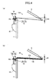
- FIG. 4(a) indicates a state where a conventional acoustic drum 10A was hit with the stick S
- FIG. 4(b) indicates a state where the acoustic drum 10 was hit with the stick S.
- the acoustic drum 10A is configured similarly to the acoustic drum 10. In FIG. 4(a) , therefore, parts similar to those of the acoustic drum 10 are given numerals similar to those given in FIG. 4(b) .
- the drumhead 12 of the acoustic drum 10A and the acoustic drum 10 is displaced and vibrates.
- the sound volume of the struck sound generated by the strike is largely influenced by the maximum displacement of the drumhead 12.
- the maximum displacement of the drumhead 12 is L10A.
- the maximum displacement of the drumhead 12 is L10A.
- the maximum displacement of the drumhead 12 (the head portion 12a) to which the striking surface attachments 13a and 13b are attached is L10 which is smaller than the maximum displacement L10A of the acoustic drum 10A.
- the acoustic drum 10 Because of the existence of the striking surface attachments 13a and 13b, the acoustic drum 10 has the useful movable part which is three times heavier than that of the acoustic drum 10A. In coordination with the increased weight of the useful movable part of the acoustic drum 10, the maximum displacement of the drumhead 12 (the head portion 12a) of the acoustic drum 10 largely decreases. As a result, the sound volume of the acoustic drum 10 is reduced. In this case, the acoustic drum 10 can reduce only the sound volume, maintaining the timbre that is similar to the timbre of the acoustic drum 10A.
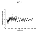
- FIG. 5 indicates resultant waveforms representative of changes in sound pressure of the respective struck sounds of the acoustic drum 10 and the acoustic drum 10A with respect to elapsed time.
- a solid line “a” indicates the waveform of the struck sound of the acoustic drum 10
- a broken line “b” indicates the waveform of the struck sound of the acoustic drum 10A.
- the maximum amplitude of the solid line "a” in response to the strike is smaller than the maximum amplitude of the broken line "b". This is brought about by the effect on the mass of the striking surface attachments 13a and 13b. In other words, it is obvious that the acoustic drum 10 can reduce the maximum amplitude of the drumhead 12 in response to the strike.
- the solid line "a” and the broken line “b” are approximately similar with each other, resulting in no difference between the struck sound of the acoustic drum 10A and the struck sound of the acoustic drum 10.
- attack and harmonics are generated at the initial phase of the strike similarly to the acoustic drum 10A.
- the struck sound of the acoustic drum 10 maintains pitches necessary for tom-toms and floor toms which are acoustic drums.
- the acoustic drum of the comparison example is obtained by attaching PET films which are identical with the striking surface attachments 13a and 13b to the front side and the reverse side of a drumhead of an acoustic drum which is identical with the above-described acoustic drum 10A, with the entire PET films being completely fastened to the front side and the reverse side of the drumhead by use of acrylic pressure-sensitive adhesive layer which is identical with the double-faced tapes 14a and 14b.
- the acoustic drum of the comparison example is identical with the acoustic drum 10 if the entire surface of each of the striking surface attachments 13a and 13b were fastened to the drumhead 12. More specifically, the acoustic drum of the comparison example is equivalent to the drum described in Description of the Related Art.
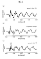
- FIG. 6(a) to (c) indicate waveforms representative of changes in the magnitude of the respective struck sounds with respect to time elapsed from the respective strikes of the drums. More specifically, FIG. 6(a) indicates a waveform of the struck sound of the acoustic drum 10A, FIG. 6(b) indicates a waveform of the struck sound of the acoustic drum of the comparison example, and FIG. 6(c) indicates a waveform of the struck sound of the acoustic drum 10.
- the resultant waveforms of FIGS. 6(a) to (c) have approximately the same shape as a whole, which reveals that respective tonic pitches (respective pitches) sustain roughly equally.
- the waveform of the acoustic drum of the comparison example indicated in FIG. 6(b) hardly has initial harmonic components, the struck sound of the acoustic drum of the comparison example has no attack to result in a muffled sound.
- the absence of harmonic components can be judged because the first peak of the waveform shown in FIG. 6(b) hardly has small vertical serrations exhibited in FIGS. 6(a) and (c) .
- Such a muffled sound having no attack makes it difficult to provide beat and to beat out a rhythm, resulting in degraded performance.
- differences between the acoustic drum 10A and acoustic drum 10, and the acoustic drum of the comparison example are not only the initial attack but also harmonic components contained in a sustained tonic pitch.
- the waveforms shown in FIGS. 6(a) and (c) are sharper than the waveform shown in FIG. 6(b) .
- this experiment reveals that the acoustic drum 10A and the acoustic drum 10 generate a struck sound having a tonic pitch containing more harmonic components than the acoustic drum of the comparison example, so that the acoustic drum 10A and the acoustic drum 10 can generate sounds having bright timbre.
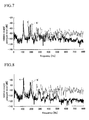
- FIG. 7 indicates results of observation in frequency domain of the struck sounds of the acoustic drum 10A and the acoustic drum 10
- FIG. 8 indicates results of observation in frequency domain of the struck sounds of the acoustic drum 10A and the acoustic drum of the comparison example.
- a solid line "a"' represents the struck sound of the acoustic drum 10
- a broken line "b"' represents the struck sound of the acoustic drum 10A
- a solid line “c” represents the struck sound of the acoustic drum of the comparison example
- a broken line "b”' represents the struck sound of the acoustic drum 10A.
- Both the broken line "b"' of FIG. 7 and the broken line “b”' of FIG. 8 represent an identical waveform.
- FIG. 7 indicates that there are no significant differences between the solid line "a"' and the broken line "b"' in a range of the order of 150 Hz to 400 Hz
- FIG. 8 indicates that harmonic components significantly decreases on the solid line "c", compared with the broken line "b"' in the range of the order of 150 Hz to 400 Hz. Therefore, it can be understood that the acoustic drum 10 can generate a struck sound which is rich in harmonic components of a tonic pitch, compared with the acoustic drum of the comparison example.
- On the right part of the waveforms shown in FIG. 7 furthermore, there are no significant differences between the solid line "a"' and the broken line "b"'.
- harmonic components abruptly decrease at the frequencies exceeding 500 Hz on the solid line "c", compared with the broken line "b"'. Therefore, it can be understood that the acoustic drum 10 can generate a struck sound also having plenty of harmonic components that bring about attack, compared with the acoustic drum of the comparison example.
- FIG. 9 represents the magnitude of the reaction force exerted when the arm hit the drumhead with respect to elapsed time.
- recessed portions in which the reaction force is smaller than or equal to 0 kgf indicate a time period in which the arm is in contact with the drumhead.
- a solid line "a"" represents the waveform of the struck sound of the acoustic drum 10
- a solid line "b”” represents the waveform of the struck sound of the acoustic drum 10A
- a broken line "c"' represents the waveform of the struck sound of the acoustic drum of the comparison example.
- the acoustic drum of the comparison example causes the strongest pain, while the acoustic drum 10A causes the smallest pain.
- the pain caused by the acoustic drum 10 is intermediate between the acoustic drum of the comparison example and the acoustic drum 10A.
- the drumhead vibrates as a thick plate as a whole, so that the drumhead of the acoustic drum of the comparison example has quite high bending stiffness to tend to cause strong pain when the player strikes the drumhead.
- the drumhead 12 and the striking surface attachments 13a and 13b vibrate as membranes. Therefore, the bending stiffness of the drumhead 12 of the acoustic drum 10 is not high, so that the pain felt by the player when he strikes the drumhead is close to the pain felt when the player plays the acoustic drum 10A.
- FIG. 10 indicates respective time periods during which the arm is in contact with the drumhead when the respective drums are struck, while FIG. 11 indicates respective maximum values of the reaction force.
- the contact time of the acoustic drum of the comparison example is 4.6 ms
- the contact time of the acoustic drum 10 is 5.7 ms
- the contact time of the acoustic drum 10A is 6.7 ms.
- the maximum value of the reaction force of the acoustic drum of the comparison example is 2.4 kgf
- the maximum value of the reaction force of the acoustic drum 10 is 2.2 kgf
- the maximum value of the reaction force of the acoustic drum 10A is 2.0 kgf.
- FIG. 12 indicates the observed results.
- FIG. 12 indicates the movement of the arm end at the time of a strike of the drumhead with the arm with respect to elapsed time. From the observed movement, the magnitude of restitution felt by the player can be read.
- a solid line "a""' represents the arm's movement observed when the acoustic drum 10 was struck
- a solid line "b""' represents the arm's movement observed when the acoustic drum 10A was struck
- a broken line “c”” represents the arm's movement observed when the acoustic drum of the comparison example was struck.
- FIG. 13 indicates the ratio between incident velocity and reflection velocity as coefficient of restitution based on the time waveforms shown in FIG. 12 .
- the coefficient of restitution for the strike on the acoustic drum 10A is 0.73
- the coefficient of restitution for the strike on the acoustic drum 10 is 0.67
- the coefficient of restitution for the strike on the acoustic drum of the comparison example is 0.55.
- the coefficient of restitution is very important in terms of player's playability.
- the drumhead of the acoustic drum of the comparison example suffers a great loss when the drumhead is struck, resulting in the unfavorable rebound of the stick S.
- the drumhead 12 and the striking surface attachments 13a and 13b vibrate as multi-ply membranes having a small loss of movability to result in a small loss caused by the strike. Therefore, the acoustic drum 10 has the restitution which is close to that of the acoustic drum 10A.
- the acoustic drum 10 is designed such that the striking surface attachments 13a and 13b are placed on the front side and the reverse side of the drumhead 12, respectively, with the outer areas of the striking surface attachments 13a and 13b being fastened to the drumhead 12.
- the drumhead 12 heavy by use of the striking surface attachments 13a and 13b to reduce the amplitude of the vibrations of a struck sound, the sound volume is efficiently reduced on the acoustic drum 10.
- the drumhead 12 and the striking surface attachments 13a and 13b vibrate as a single unit as a whole in response to a strike on the acoustic drum 10, but separately behave locally and instantly. Such behaviors maintain a struck sound having clear attack. Furthermore, because the respective central areas which are to be hit with the stick S on the striking surface attachments 13a and 13b are not fixed to the drumhead 12, the striking surface attachments 13a and 13b never cause ill effect on struck sounds. As a result, the acoustic drum 10 can provide a player with sound quality and feeling of striking which are similar to the sound quality and the feeling provided by conventional acoustic drums. Therefore, the acoustic drum 10 does not impair playability in spite of the existence of the striking surface attachments 13a and 13b.
- FIG. 14 shows an acoustic drum 20 according to the second embodiment of the present invention.
- the acoustic drum 20 has a hollow cylindrical shell 21 which is a drum shell, a circular drumhead 22 mounted on the upper opening end of the shell 21, and a circular resonance head 27 mounted on the lower opening end of the shell 21.
- the drumhead 22 is formed of a head portion 22a and a flesh hoop 22b. To the front side and the reverse side of the head portion 22a, striking surface attachments 23a and 23b are attached with double-faced tapes 24a and 24b.
- the drumhead 22 is mounted on the upper opening end of the shell 21 by six lugs 25 provided on the outer peripheral surface of the shell 21 and a stretching portion 26 formed of a hoop 26a including engaging projections 26c and tuning bolts 26b.
- the lugs 25 are placed such that the lower end of each lug 25 is situated slightly above the vertical center of the shell 21.
- the shell 21, the drumhead 22, the striking surface attachments 23a and 23b, the double-faced tapes 24a and 24b, the lugs 25 and the stretching portion 26 are configured similarly to the shell 11, the drumhead 12, the striking surface attachments 13a and 13b, the double-faced tapes 14a and 14b, the lugs 15 and the stretching portion 16 of the above-described first embodiment.
- the acoustic drum 20 is identical with the acoustic drum 10 if the resonance head 27 were excluded from the acoustic drum 20, with the lugs 25 being moved upward.
- the resonance head 27 is formed of a circular head portion 27a made of the same PET film as the head portion 22a and a flesh hoop 27b which is the same metal ring as the flesh hoop 22b.
- the resonance head 27 is mounted on the lower opening end of the shell 21 through six lugs 28 and a stretching portion 29 provided to be vertically symmetrical with the lugs 25 and the stretching portion 26 so that the resonance head 27 can be attached/detached to/from the lower opening end of the shell 21 by a manner similar to the drumhead 22 though the direction is switched upside down.
- respective thread portions of respective tuning bolts 29b provided on the stretching portion 29 are inserted into bolt-inserting holes of engaging projections 29c provided on the hoop 29a to engage the thread portions in respective screw holes of the lugs 28.
- the tension of the resonance head 27 can be adjusted.
- the drumhead 22 When the striking surface of the acoustic drum 20 configured as above is hit with the stick S, the drumhead 22 is displaced along with the striking surface attachments 23a and 23b. In this case, the drumhead 22 and the striking surface attachments 23a and 23b vibrate similarly to the above-described drumhead 12 and the striking surface attachments 13a and 13b. By the displacement of the drumhead 22 and the striking surface attachments 23a and 23b, furthermore, the air within the shell 21 is compressed, so that the compressed air presses the resonance head 27 downward to deform the resonance head 27.
- the operational advantage of the acoustic drum 20 other than the above is the same as that of the acoustic drum 10.
- FIG. 15 indicates an acoustic drum 30 according to the third embodiment of the present invention.
- the acoustic drum 30 is designed such that to the front side (underside) of a head portion 37a of a resonance head 37, a non-striking surface attachment 33a is attached with a double-faced tape 34a, while a non-striking surface attachment 33b is attached to the reverse side (inner surface) of the head portion 37a with a double-faced tape 34b.
- the non-striking surface attachments 33a and 33b are configured similarly to the above-described striking surface attachments 23a and 23b to be attached to the head portion 37a by the similar manner by which the striking surface attachments 23a and 23b are attached. Except the non-striking surface attachments 33a and 33b, the acoustic drum 30 is configured similarly to the above-described acoustic drum 20. Therefore, similar components are given similar numerals to omit explanations of the components.
- the acoustic drum 30 can achieve reduction in sound volume more efficiently than the acoustic drum 20.
- the operational advantage of the acoustic drum 30 other than the above is the same as that of the acoustic drum 20 of the second embodiment.
- FIG. 16 indicates an acoustic drum 40 according to the fourth embodiment of the present invention.
- the acoustic drum 40 is designed such that a sound-absorbing member 42 is provided on a part of an inner peripheral surface of a shell 41.
- the sound-absorbing member 42 is formed of urethane foam having a thickness (lateral length) of 25 mm, a vertical length of 100 mm, a length of 150 mm measured along a circumferential direction of the inner peripheral surface of the shell 41, and a density of 20kg/m 3 .
- the sound-absorbing member 42 is attached with adhesive to be situated at the vertical center of the inner peripheral surface of the shell 41. Except the sound-absorbing member 42, the acoustic drum 40 is configured similarly to the above-described acoustic drum 10. Therefore, similar components are given similar numerals to omit explanations of the components.
- the acoustic drum 40 can efficiently reduce internal resonance generated inside the shell 41.
- the drumhead 12 is made heavier by attaching the striking surface attachments 13a and 13b, furthermore, the internal resonance of the shell 41 tends to be reinforced.
- the resonance can be absorbed by the sound-absorbing member 42 provided on the shell 41.
- the operational advantage of the acoustic drum 40 other than the above is the same as that of the acoustic drum 10 of the first embodiment.
- FIG. 17 indicates an acoustic drum 50 according to the fifth embodiment of the present invention.
- the acoustic drum 50 is designed such that a sound-absorbing member 52 configured similarly to the above-described sound-absorbing member 42 is provided on a part of an inner peripheral surface of a shell 51. Except the sound-absorbing member 52, the acoustic drum 50 is configured similarly to the above-described acoustic drum 30 of the third embodiment. Therefore, similar components are given similar numerals to omit explanations of the components.
- the acoustic drum 50 has higher effect on reduction in sound volume than the acoustic drums 10 to 40 of the above-described embodiments, also achieving reduction in resonance produced within the shell 51.
- FIG. 18 indicates a main portion of an acoustic drum 60 according to the first modification of the above-described first embodiment.
- the acoustic drum 60 is designed such that respective fixing portions 65 by which striking surface attachments 63a and 63b are fixed to a head portion 62a of a drumhead 62 are respective outer areas of the striking surface attachments 63a and 63b, and have a width of 5 mm measured from the outer end of the striking surface attachments 63a and 63b.
- the acoustic drum 60 is also a 12-inch acoustic drum.
- the minimum width of the fixing portions 65 is defined at 5 mm, which is the minimum value that can prevent the striking surface attachments 63a and 63b from coming unstuck from the head portion 62a by tension and strikes. Therefore, the acoustic drum 60 can yield the maximum effect with the minimum fixing strength.
- FIG. 19 indicates a main portion of an acoustic drum 70 according to the second modification of the above-described first embodiment.
- the acoustic drum 70 is designed such that respective fixing portions 75 by which striking surface attachments 73a and 73b are fixed to a head portion 72a of a drumhead 72 are respective outer areas of the striking surface attachments 73a and 73b, and have a width of 50% of the radius of the head portion 72a, ranging from the outer end of the striking surface attachments 73a and 73b.
- the acoustic drum 70 is also a 12-inch acoustic drum.
- the maximum width of the fixing portions 75 is defined at 50% of the radius of the head portion 72a.
- the thus designed acoustic drum 70 has the fixing portions 75 of the maximum area to securely prevent the striking surface attachments 73a and 73b from coming unstuck from the head portion 72a, also providing attack.
- the width in the radius direction of the fixing portions of the 12-inch acoustic drum is set at any desired value falling within a range from 5 mm to 50% of the radius of the head portion. This range can be also applied to the acoustic drums 20 to 50 of the second to fifth embodiments. In addition, it is preferable that the width of the fixing portions of the non-striking surface attachments 33a and 33b of the third and fifth embodiments is set within this range. If the acoustic drum varies in size, the width of the fixing portions of the acoustic drum also varies according to the size.
- the width of the fixing portions of the acoustic drum should be changed so as to make the width of the fixing portion be approximately proportional to the diameter of the acoustic drum.
- the range can be thus applied to any acoustic drums of various sizes.
- FIG. 20 indicates a main portion of an acoustic drum 80 according to the third modification of the above-described first embodiment.
- the acoustic drum 80 is designed such that respective fixing portions 85 by which striking surface attachments 83a and 83b are fixed to a head portion 82a of a drumhead 82 are formed not of one unit which is the entire outer area but of a plurality of parts which are apart from each other with regular intervals being provided between the parts.
- the fixing portions 85 make up 50% of the whole circumference to have a width of 10 mm.
- the acoustic drum 80 is also a 12-inch acoustic drum. The acoustic drum of this size can yield sufficient effect with the above-described fixing portions 85.
- the fixing portions 85 can be also applied to the acoustic drums 20 to 50 of the second to fifth embodiments.
- FIG. 21 indicates a main portion of an acoustic drum 90 according to the fourth modification of the above-described first embodiment.
- the acoustic drum 90 is designed such that a fixing portion 95 by which striking surface attachments 93a and 93b are fixed to a head portion 92a of a drumhead 92 is formed of a plurality of parts which are provided on the outer area to be apart from each other with regular intervals being provided between the parts, and a plurality of parts provided inside the outer area. More specifically, the fixing portion 95 is formed of the parts configured similarly to the fixing portion 85, and the parts situated inside so that each of these parts will have the same size.
- the fixing portion 95 is also a 12-inch acoustic drum.
- the acoustic drum of this size can yield sufficient effect with the above-described fixing portion 95.
- the fixing portion 95 can be also applied to the acoustic drums 20 to 50 of the second to fifth embodiments.
- FIG. 22 indicates a main portion of an acoustic drum 100 according to the fifth modification of the above-described first embodiment.
- the acoustic drum 100 is designed such that a fixing portion 105 by which striking surface attachments 103a and 103b are fixed to a head portion 102a of a drumhead 102 is formed of a plurality of parts which are placed randomly on the outer area.
- the acoustic drum 100 can also yield sufficient effect with the above-described fixing portion 105.
- the fixing portion 105 can be also applied to the acoustic drums 20 to 50 of the second to fifth embodiments.
- the sound-absorbing member 42, 52 may be used for the acoustic drums 10 to 30 of the first to third embodiments and their modifications.
- the acoustic drum according to the present invention is not limited to the above-described embodiments and their modifications, but can be further modified.
- the acoustic drum of each embodiment is designed such that the striking surface attachment 13a or the like is provided on the front side of the head portion 12a or the like with the striking surface attachment 13b or the like being provided on the reverse side of the head portion 12a or the like
- the acoustic drum may be designed to have only the striking surface attachment 13a or the like, or only the striking surface attachment 13b or the like.
- the acoustic drum may be designed such that a plurality of striking surface attachments are provided on the front side or the reverse side of the head portion 12a or the like.
- the acoustic drum may be designed to have one of the non-striking surface attachments 33a and 33b, or to have a plurality of non-striking surface attachments on the front side or the reverse side of the head portion 37a.
- the way by which the striking surface attachments 13a and 13b, and the non-striking surface attachments 33a and 33b are fixed to the head portion 12a and the head portion 37a is not limited to adhesion by use of the double-faced tape 14a and the like, but may be fixing by use of a bonding adhesive or by use of a fixing member such as rivets or staples of stapler.
- the material of the head portions 12a and the like, the striking surface attachments 13a and the like, and the non-striking surface attachments 33a and the like is not limited to PET film, but may be any other high polymer film having characteristics similar to PET film such as PEN film.
- As the sound-absorbing member 42 and the like not only urethane foam but also glass wool fiber material, sponge or the like can be used.
- the drumhead 12 to which the striking surface attachments 13a, 13b and the like are attached, and the resonance head 37 to which the non-striking surface attachments 33a, 33b and the like are attached may be either previously incorporated into the acoustic drum or separately added. In the case of separately adding, it is preferable to prepare different kinds of drumheads and resonance heads so that a player can choose and use a player's desired one. In the different kinds of drumheads and resonance heads, the striking surface attachments 13a, 13b and the non-striking surface attachments 33a, 33b have different fixing portions respectively.
- the player can choose player's desired striking surface attachments and non-striking surface attachments according to the player's purpose to fix the selected striking surface attachments and non-striking surface attachments to the drumhead and the resonance head.
- the different kinds of striking surface attachments and the non-striking surface attachments have different fixing portions respectively.
- acoustic drum according to the present invention can be applied to acoustic drums of various sizes ranging from small acoustic drums to large acoustic drums irrespective of size.
- the other configurations of the acoustic drum 10 and the like can be also modified within the technical scope of the present invention.
Landscapes
- Physics & Mathematics (AREA)
- Engineering & Computer Science (AREA)
- Acoustics & Sound (AREA)
- Multimedia (AREA)
- Electrophonic Musical Instruments (AREA)
Applications Claiming Priority (1)
| Application Number | Priority Date | Filing Date | Title |
|---|---|---|---|
| JP2012201860A JP5751229B2 (ja) | 2012-09-13 | 2012-09-13 | アコースティックドラム |
Publications (2)
| Publication Number | Publication Date |
|---|---|
| EP2709100A2 true EP2709100A2 (de) | 2014-03-19 |
| EP2709100A3 EP2709100A3 (de) | 2017-05-17 |
Family
ID=49170540
Family Applications (1)
| Application Number | Title | Priority Date | Filing Date |
|---|---|---|---|
| EP13020097.5A Withdrawn EP2709100A3 (de) | 2012-09-13 | 2013-09-13 | Akustische Trommel |
Country Status (4)
| Country | Link |
|---|---|
| US (1) | US8916759B2 (de) |
| EP (1) | EP2709100A3 (de) |
| JP (1) | JP5751229B2 (de) |
| CN (1) | CN103680480B (de) |
Families Citing this family (14)
| Publication number | Priority date | Publication date | Assignee | Title |
|---|---|---|---|---|
| JP5747884B2 (ja) * | 2012-09-13 | 2015-07-15 | ヤマハ株式会社 | バスドラム |
| JP5751229B2 (ja) * | 2012-09-13 | 2015-07-22 | ヤマハ株式会社 | アコースティックドラム |
| US20150122107A1 (en) * | 2013-11-01 | 2015-05-07 | David C. deLoache | Interchangeable drum head cover |
| US9159305B1 (en) * | 2014-04-11 | 2015-10-13 | Kris Adam Mazzarisi | Pitch and tone altering drum cover |
| JP6390293B2 (ja) * | 2014-09-16 | 2018-09-19 | ヤマハ株式会社 | ドラム |
| US9396712B1 (en) * | 2014-10-23 | 2016-07-19 | Ronn Dunnett | Multi layer drumhead with non-concentric inner layer |
| JP6439534B2 (ja) * | 2015-03-25 | 2018-12-19 | ヤマハ株式会社 | ドラム |
| US10163426B2 (en) * | 2015-09-04 | 2018-12-25 | Roland Corporation | Bass drum damper and bass drum |
| TWM548340U (zh) * | 2017-05-24 | 2017-09-01 | Sound And Light Co Ltd | 可抑制音源雜訊的電子打擊樂器 |
| US20190139521A1 (en) * | 2017-11-06 | 2019-05-09 | Hpi (Tianjin) Musical Instrument Co., Ltd. | Tuning Ring for Adjusting Sound Timbre of Drum Head |
| TWI651713B (zh) * | 2018-09-28 | 2019-02-21 | 功學社教育用品股份有限公司 | 多用鼓 |
| JP2021103257A (ja) | 2019-12-25 | 2021-07-15 | ローランド株式会社 | ドラムヘッド及びクッションの取付方法 |
| JP7322222B1 (ja) * | 2022-03-08 | 2023-08-07 | キヤノン株式会社 | 転写ユニット、画像形成装置及び転写ユニットの製造方法 |
| CN116259287B (zh) * | 2022-12-12 | 2025-07-29 | 得理乐器(珠海)有限公司 | 一种测试鼓寿命的装置及测试方法 |
Citations (1)
| Publication number | Priority date | Publication date | Assignee | Title |
|---|---|---|---|---|
| JPH034768A (ja) | 1989-05-30 | 1991-01-10 | Nikken Food Kk | 乳酸菌調製物 |
Family Cites Families (47)
| Publication number | Priority date | Publication date | Assignee | Title |
|---|---|---|---|---|
| US879521A (en) * | 1907-10-05 | 1908-02-18 | Julius Chein | Toy drum. |
| US1654592A (en) * | 1924-05-20 | 1928-01-03 | Rudolph Wurlitzer Mfg Co | Drum |
| US1809050A (en) * | 1929-02-23 | 1931-06-09 | George H Logan | Head for musical instruments |
| JPS5855422Y2 (ja) * | 1975-12-15 | 1983-12-19 | ヤマハ株式会社 | ドラムヨウヘツド |
| US4102235A (en) * | 1976-08-19 | 1978-07-25 | Le Masters Laurence G | Drum practice pad |
| US4308782A (en) * | 1979-10-04 | 1982-01-05 | Remo, Incorporated | Laminated head of plastic sheet material and a synthetic fabric material having random fiber orientation |
| US4325281A (en) | 1980-07-02 | 1982-04-20 | Silver Street, Incorporated | Drumhead ring reducer |
| JPS57115095U (de) * | 1981-01-05 | 1982-07-16 | ||
| US4567807A (en) | 1982-11-29 | 1986-02-04 | Robinson David F | Muting and muffling of drums |
| US4589323A (en) | 1983-04-29 | 1986-05-20 | Remo, Inc. | Drum muffler |
| JPS6161593U (de) * | 1984-09-27 | 1986-04-25 | ||
| JPS636494U (de) | 1986-06-30 | 1988-01-16 | ||
| JPS6454095U (de) * | 1987-09-30 | 1989-04-04 | ||
| US4742753A (en) | 1987-10-07 | 1988-05-10 | Zay Speed | Drumhead with framed aperture |
| JPH07117830B2 (ja) * | 1990-04-12 | 1995-12-18 | ヤマハ株式会社 | 打楽器用ウエイト |
| US5159139A (en) | 1990-06-13 | 1992-10-27 | Evans Products, Inc. | Drumhead with overtone suppression |
| DE9213980U1 (de) * | 1992-10-16 | 1992-12-24 | Schneider, Ingold, 5628 Heiligenhaus | Schlagfläche mit Abstandhalter für Trommeln insbesondere für die große Trommel eines Schlagzeuges |
| JP3004768U (ja) * | 1994-05-30 | 1994-11-22 | 星野楽器株式会社 | 消音ドラムヘッド |
| US5492047A (en) | 1994-10-20 | 1996-02-20 | Oliveri; Ignazus P. | Sound muffling, tone maintaining drum practice apparatus |
| US6927330B2 (en) | 2003-06-24 | 2005-08-09 | Randall L. May | Drum with modulated acoustic air vent |
| US5892168A (en) | 1996-09-25 | 1999-04-06 | Aquarian Accessories Corporation | Drum head with floating muffling ring |
| US5864077A (en) * | 1997-05-15 | 1999-01-26 | Innovative Automation, Inc. | Drumhead |
| US6043420A (en) | 1999-04-27 | 2000-03-28 | Arnold; Richard N. | Bass drum pillow muffle |
| JP3835084B2 (ja) | 1999-11-15 | 2006-10-18 | ヤマハ株式会社 | ドラム、減音装置および電子打楽器用ヘッド |
| US6245979B1 (en) | 1999-12-17 | 2001-06-12 | J. D'addario & Company, Inc. | Floating staccato waffle disk |
| US6297177B1 (en) * | 2000-07-24 | 2001-10-02 | Remo, Inc. | Drumhead construction |
| US6291753B1 (en) * | 2000-02-22 | 2001-09-18 | J. D'addario & Company, Inc. | Marching snare drumhead patch |
| US6291754B1 (en) | 2000-11-15 | 2001-09-18 | J. D'addario & Company, Inc. | Externally mounted adjustable damping system for drum head |
| US6518490B2 (en) * | 2001-01-23 | 2003-02-11 | Drum Workshop, Inc. | Drum head with sound attenuating center coating |
| US6580023B2 (en) * | 2001-08-13 | 2003-06-17 | Remo, Inc. | Convertible drumhead |
| US6686526B2 (en) * | 2001-10-17 | 2004-02-03 | Leonard E. Ezbicki | Percussion practice aid |
| US6949701B2 (en) | 2002-01-18 | 2005-09-27 | Yamaha Corporation | Drumhead |
| JP3656633B2 (ja) * | 2002-01-18 | 2005-06-08 | ヤマハ株式会社 | ドラム用ヘッド |
| JP4042616B2 (ja) | 2003-01-31 | 2008-02-06 | ヤマハ株式会社 | ドラムヘッドとドラムおよび電子ドラム並びにドラムシステムと電子ドラムシステム |
| ATE298452T1 (de) * | 2003-02-12 | 2005-07-15 | Hans-Peter Wilfer | Dämpfungselement für trommel mit mikrophonhalterung |
| US7074994B2 (en) | 2003-07-28 | 2006-07-11 | Remo, Inc. | Tunable drumhead |
| US7214867B1 (en) | 2004-02-13 | 2007-05-08 | J. D'addario & Company, Inc. | Drumhead tone control device |
| CA2560622A1 (en) * | 2005-09-22 | 2007-03-22 | Jeffrey J. Sharp | Viscoelastic polymer damping for percussion instruments |
| JP5136825B2 (ja) * | 2007-03-09 | 2013-02-06 | ヤマハ株式会社 | ドラムヘッド及び該ドラムヘッドを備えた電子ドラム |
| US20100175535A1 (en) | 2009-01-12 | 2010-07-15 | Lento James A | Percussion resonance system |
| US8148617B2 (en) * | 2009-05-08 | 2012-04-03 | Yamaha Corporation | Drum pad and manufacturing method thereof |
| USD611524S1 (en) | 2009-08-28 | 2010-03-09 | Famous Drum Company, Llc | Drum ring |
| US20130042744A1 (en) | 2011-08-16 | 2013-02-21 | Chao-Ying HSIEN | Silent drumhead |
| JP6151498B2 (ja) * | 2012-09-04 | 2017-06-21 | ローランド株式会社 | ドラムヘッド |
| JP5747884B2 (ja) * | 2012-09-13 | 2015-07-15 | ヤマハ株式会社 | バスドラム |
| JP5751229B2 (ja) * | 2012-09-13 | 2015-07-22 | ヤマハ株式会社 | アコースティックドラム |
| US20140144309A1 (en) * | 2012-11-26 | 2014-05-29 | Edward Philip Cawthorne | Drumhead Cover System |
-
2012
- 2012-09-13 JP JP2012201860A patent/JP5751229B2/ja not_active Expired - Fee Related
-
2013
- 2013-09-12 US US14/025,329 patent/US8916759B2/en active Active
- 2013-09-13 EP EP13020097.5A patent/EP2709100A3/de not_active Withdrawn
- 2013-09-13 CN CN201310418966.2A patent/CN103680480B/zh not_active Expired - Fee Related
Patent Citations (1)
| Publication number | Priority date | Publication date | Assignee | Title |
|---|---|---|---|---|
| JPH034768A (ja) | 1989-05-30 | 1991-01-10 | Nikken Food Kk | 乳酸菌調製物 |
Also Published As
| Publication number | Publication date |
|---|---|
| CN103680480B (zh) | 2016-10-12 |
| JP5751229B2 (ja) | 2015-07-22 |
| US8916759B2 (en) | 2014-12-23 |
| EP2709100A3 (de) | 2017-05-17 |
| CN103680480A (zh) | 2014-03-26 |
| JP2014056178A (ja) | 2014-03-27 |
| US20140069257A1 (en) | 2014-03-13 |
Similar Documents
| Publication | Publication Date | Title |
|---|---|---|
| US8916759B2 (en) | Acoustic drum | |
| EP2709099B1 (de) | Basstrommel | |
| EP2571017B1 (de) | Musikinstrument mit Texturauftragungen | |
| EP2690617B1 (de) | Schlingentrommel | |
| JP3835084B2 (ja) | ドラム、減音装置および電子打楽器用ヘッド | |
| EP1837860A2 (de) | Elektronisches Schlagzeuginstrument | |
| US7968780B2 (en) | Method and apparatus for optimizing sound output characteristics of a drum | |
| AU755145B2 (en) | Externally mounted adjustable damping system for drum head | |
| US5998716A (en) | Impact resistant marching tom tom drum head | |
| US5986196A (en) | Impact pad for a drum head | |
| TWI459371B (zh) | 樂器頭部之安裝裝置 | |
| JP5163099B2 (ja) | 電子打楽器 | |
| JP6221617B2 (ja) | ドラム | |
| JP2005274727A (ja) | 打楽器用パッド | |
| JP3615043B2 (ja) | ドラムヘッド及びこのドラムヘッドを用いた消音ドラム、消音スネアドラム | |
| JP2003271134A (ja) | 電子シンバル | |
| EP3843082B1 (de) | Trommelkopf und befestigungverfahren von dämpfungsschichten | |
| WO2009110838A1 (en) | Drum head for electronic percussion instrument | |
| CN222482940U (zh) | 一种打击乐器用鼓槌的槌头减震套 | |
| US12620374B2 (en) | Drum enhancement assembly | |
| US20040216583A1 (en) | Apparatus and methods for enhancing the sound of a musical instrument | |
| WO2023127128A1 (ja) | 打楽器および打楽器の音量の減音方法 | |
| US20200402491A1 (en) | A reverberating percussion instrument | |
| CN110660372A (zh) | 一种新型钢琴榔头 | |
| WO2020163938A1 (en) | Tone-enhancing drum shell and methods of making and using same |
Legal Events
| Date | Code | Title | Description |
|---|---|---|---|
| PUAI | Public reference made under article 153(3) epc to a published international application that has entered the european phase |
Free format text: ORIGINAL CODE: 0009012 |
|
| AK | Designated contracting states |
Kind code of ref document: A2 Designated state(s): AL AT BE BG CH CY CZ DE DK EE ES FI FR GB GR HR HU IE IS IT LI LT LU LV MC MK MT NL NO PL PT RO RS SE SI SK SM TR |
|
| AX | Request for extension of the european patent |
Extension state: BA ME |
|
| PUAL | Search report despatched |
Free format text: ORIGINAL CODE: 0009013 |
|
| AK | Designated contracting states |
Kind code of ref document: A3 Designated state(s): AL AT BE BG CH CY CZ DE DK EE ES FI FR GB GR HR HU IE IS IT LI LT LU LV MC MK MT NL NO PL PT RO RS SE SI SK SM TR |
|
| AX | Request for extension of the european patent |
Extension state: BA ME |
|
| RIC1 | Information provided on ipc code assigned before grant |
Ipc: G10D 13/02 20060101AFI20170408BHEP |
|
| 17P | Request for examination filed |
Effective date: 20171117 |
|
| RBV | Designated contracting states (corrected) |
Designated state(s): AL AT BE BG CH CY CZ DE DK EE ES FI FR GB GR HR HU IE IS IT LI LT LU LV MC MK MT NL NO PL PT RO RS SE SI SK SM TR |
|
| 17Q | First examination report despatched |
Effective date: 20191210 |
|
| STAA | Information on the status of an ep patent application or granted ep patent |
Free format text: STATUS: THE APPLICATION HAS BEEN WITHDRAWN |
|
| 18W | Application withdrawn |
Effective date: 20200204 |