EP2708361B1 - Procédé de nettoyage d'éjecteur de gouttelettes, nettoyeur pour éjecteur de gouttelettes et appareil de production de matériau particulaire à l'aide du nettoyeur - Google Patents
Procédé de nettoyage d'éjecteur de gouttelettes, nettoyeur pour éjecteur de gouttelettes et appareil de production de matériau particulaire à l'aide du nettoyeur Download PDFInfo
- Publication number
- EP2708361B1 EP2708361B1 EP13184141.3A EP13184141A EP2708361B1 EP 2708361 B1 EP2708361 B1 EP 2708361B1 EP 13184141 A EP13184141 A EP 13184141A EP 2708361 B1 EP2708361 B1 EP 2708361B1
- Authority
- EP
- European Patent Office
- Prior art keywords
- liquid
- cleaning
- cleaning liquid
- nozzles
- toner
- Prior art date
- Legal status (The legal status is an assumption and is not a legal conclusion. Google has not performed a legal analysis and makes no representation as to the accuracy of the status listed.)
- Active
Links
- 238000004140 cleaning Methods 0.000 title claims description 448
- 238000000034 method Methods 0.000 title claims description 115
- 239000011236 particulate material Substances 0.000 title claims description 111
- 238000004519 manufacturing process Methods 0.000 title claims description 63
- 239000007788 liquid Substances 0.000 claims description 668
- 239000000203 mixture Substances 0.000 claims description 235
- 229920005989 resin Polymers 0.000 claims description 68
- 239000011347 resin Substances 0.000 claims description 68
- 239000000463 material Substances 0.000 claims description 33
- VYPSYNLAJGMNEJ-UHFFFAOYSA-N Silicium dioxide Chemical compound O=[Si]=O VYPSYNLAJGMNEJ-UHFFFAOYSA-N 0.000 claims description 31
- 239000002904 solvent Substances 0.000 claims description 31
- 230000001846 repelling effect Effects 0.000 claims description 28
- 229910052681 coesite Inorganic materials 0.000 claims description 15
- 229910052906 cristobalite Inorganic materials 0.000 claims description 15
- 229910052682 stishovite Inorganic materials 0.000 claims description 15
- 229910052905 tridymite Inorganic materials 0.000 claims description 15
- 239000000377 silicon dioxide Substances 0.000 claims description 14
- 238000007599 discharging Methods 0.000 claims description 9
- 125000000217 alkyl group Chemical group 0.000 claims description 5
- 238000003825 pressing Methods 0.000 claims description 5
- 125000005010 perfluoroalkyl group Chemical group 0.000 claims description 4
- 239000002245 particle Substances 0.000 description 123
- XEKOWRVHYACXOJ-UHFFFAOYSA-N Ethyl acetate Chemical compound CCOC(C)=O XEKOWRVHYACXOJ-UHFFFAOYSA-N 0.000 description 58
- 238000009826 distribution Methods 0.000 description 40
- 239000001993 wax Substances 0.000 description 28
- 239000011230 binding agent Substances 0.000 description 25
- 239000003086 colorant Substances 0.000 description 22
- 230000008569 process Effects 0.000 description 21
- WYURNTSHIVDZCO-UHFFFAOYSA-N Tetrahydrofuran Chemical compound C1CCOC1 WYURNTSHIVDZCO-UHFFFAOYSA-N 0.000 description 20
- 238000001035 drying Methods 0.000 description 19
- 239000000696 magnetic material Substances 0.000 description 16
- ZWEHNKRNPOVVGH-UHFFFAOYSA-N 2-Butanone Chemical compound CCC(C)=O ZWEHNKRNPOVVGH-UHFFFAOYSA-N 0.000 description 15
- 230000001965 increasing effect Effects 0.000 description 15
- 239000002253 acid Substances 0.000 description 14
- 239000000654 additive Substances 0.000 description 12
- 239000003795 chemical substances by application Substances 0.000 description 12
- 239000006185 dispersion Substances 0.000 description 12
- 239000004594 Masterbatch (MB) Substances 0.000 description 11
- 238000011156 evaluation Methods 0.000 description 11
- UQSXHKLRYXJYBZ-UHFFFAOYSA-N iron oxide Inorganic materials [Fe]=O UQSXHKLRYXJYBZ-UHFFFAOYSA-N 0.000 description 11
- -1 magnetite Chemical class 0.000 description 11
- KWYUFKZDYYNOTN-UHFFFAOYSA-M Potassium hydroxide Chemical compound [OH-].[K+] KWYUFKZDYYNOTN-UHFFFAOYSA-M 0.000 description 10
- 239000002270 dispersing agent Substances 0.000 description 10
- 230000000694 effects Effects 0.000 description 10
- 229920001225 polyester resin Polymers 0.000 description 10
- 239000004645 polyester resin Substances 0.000 description 10
- YLQBMQCUIZJEEH-UHFFFAOYSA-N tetrahydrofuran Natural products C=1C=COC=1 YLQBMQCUIZJEEH-UHFFFAOYSA-N 0.000 description 10
- 239000000049 pigment Substances 0.000 description 9
- 239000007787 solid Substances 0.000 description 9
- 238000005227 gel permeation chromatography Methods 0.000 description 8
- 238000002360 preparation method Methods 0.000 description 8
- 230000015572 biosynthetic process Effects 0.000 description 7
- 230000008859 change Effects 0.000 description 7
- 235000013980 iron oxide Nutrition 0.000 description 7
- 238000002844 melting Methods 0.000 description 7
- 230000008018 melting Effects 0.000 description 7
- 238000006116 polymerization reaction Methods 0.000 description 7
- 229920002554 vinyl polymer Polymers 0.000 description 7
- LFQSCWFLJHTTHZ-UHFFFAOYSA-N Ethanol Chemical compound CCO LFQSCWFLJHTTHZ-UHFFFAOYSA-N 0.000 description 6
- PXHVJJICTQNCMI-UHFFFAOYSA-N Nickel Chemical compound [Ni] PXHVJJICTQNCMI-UHFFFAOYSA-N 0.000 description 6
- YXFVVABEGXRONW-UHFFFAOYSA-N Toluene Chemical compound CC1=CC=CC=C1 YXFVVABEGXRONW-UHFFFAOYSA-N 0.000 description 6
- 239000011324 bead Substances 0.000 description 6
- 239000004203 carnauba wax Substances 0.000 description 6
- 235000013869 carnauba wax Nutrition 0.000 description 6
- 230000003247 decreasing effect Effects 0.000 description 6
- 230000006866 deterioration Effects 0.000 description 6
- 239000007789 gas Substances 0.000 description 6
- 229910010272 inorganic material Inorganic materials 0.000 description 6
- 239000011147 inorganic material Substances 0.000 description 6
- SZVJSHCCFOBDDC-UHFFFAOYSA-N iron(II,III) oxide Inorganic materials O=[Fe]O[Fe]O[Fe]=O SZVJSHCCFOBDDC-UHFFFAOYSA-N 0.000 description 6
- 229910052751 metal Inorganic materials 0.000 description 6
- 239000002184 metal Substances 0.000 description 6
- CSCPPACGZOOCGX-UHFFFAOYSA-N Acetone Chemical compound CC(C)=O CSCPPACGZOOCGX-UHFFFAOYSA-N 0.000 description 5
- 238000006243 chemical reaction Methods 0.000 description 5
- 238000002474 experimental method Methods 0.000 description 5
- 238000002156 mixing Methods 0.000 description 5
- YCKRFDGAMUMZLT-UHFFFAOYSA-N Fluorine atom Chemical compound [F] YCKRFDGAMUMZLT-UHFFFAOYSA-N 0.000 description 4
- XEEYBQQBJWHFJM-UHFFFAOYSA-N Iron Chemical compound [Fe] XEEYBQQBJWHFJM-UHFFFAOYSA-N 0.000 description 4
- FYYHWMGAXLPEAU-UHFFFAOYSA-N Magnesium Chemical compound [Mg] FYYHWMGAXLPEAU-UHFFFAOYSA-N 0.000 description 4
- 239000006087 Silane Coupling Agent Substances 0.000 description 4
- RTAQQCXQSZGOHL-UHFFFAOYSA-N Titanium Chemical compound [Ti] RTAQQCXQSZGOHL-UHFFFAOYSA-N 0.000 description 4
- XLOMVQKBTHCTTD-UHFFFAOYSA-N Zinc monoxide Chemical compound [Zn]=O XLOMVQKBTHCTTD-UHFFFAOYSA-N 0.000 description 4
- MCMNRKCIXSYSNV-UHFFFAOYSA-N Zirconium dioxide Chemical compound O=[Zr]=O MCMNRKCIXSYSNV-UHFFFAOYSA-N 0.000 description 4
- 229910052782 aluminium Inorganic materials 0.000 description 4
- XAGFODPZIPBFFR-UHFFFAOYSA-N aluminium Chemical compound [Al] XAGFODPZIPBFFR-UHFFFAOYSA-N 0.000 description 4
- 239000006229 carbon black Substances 0.000 description 4
- 239000011737 fluorine Substances 0.000 description 4
- 229910052731 fluorine Inorganic materials 0.000 description 4
- 229910052451 lead zirconate titanate Inorganic materials 0.000 description 4
- 229910052749 magnesium Inorganic materials 0.000 description 4
- 239000011777 magnesium Substances 0.000 description 4
- 239000005871 repellent Substances 0.000 description 4
- 229920002545 silicone oil Polymers 0.000 description 4
- 239000002699 waste material Substances 0.000 description 4
- 239000002033 PVDF binder Substances 0.000 description 3
- 239000004698 Polyethylene Substances 0.000 description 3
- 230000002776 aggregation Effects 0.000 description 3
- 150000001412 amines Chemical class 0.000 description 3
- 239000000919 ceramic Substances 0.000 description 3
- 239000010941 cobalt Substances 0.000 description 3
- 229910017052 cobalt Inorganic materials 0.000 description 3
- GUTLYIVDDKVIGB-UHFFFAOYSA-N cobalt atom Chemical compound [Co] GUTLYIVDDKVIGB-UHFFFAOYSA-N 0.000 description 3
- 229920001577 copolymer Polymers 0.000 description 3
- 235000014113 dietary fatty acids Nutrition 0.000 description 3
- 238000000113 differential scanning calorimetry Methods 0.000 description 3
- 239000000194 fatty acid Substances 0.000 description 3
- 229930195729 fatty acid Natural products 0.000 description 3
- 239000012535 impurity Substances 0.000 description 3
- VBMVTYDPPZVILR-UHFFFAOYSA-N iron(2+);oxygen(2-) Chemical class [O-2].[Fe+2] VBMVTYDPPZVILR-UHFFFAOYSA-N 0.000 description 3
- JEIPFZHSYJVQDO-UHFFFAOYSA-N iron(III) oxide Inorganic materials O=[Fe]O[Fe]=O JEIPFZHSYJVQDO-UHFFFAOYSA-N 0.000 description 3
- 150000002739 metals Chemical class 0.000 description 3
- 239000000178 monomer Substances 0.000 description 3
- 239000003960 organic solvent Substances 0.000 description 3
- 229920000573 polyethylene Polymers 0.000 description 3
- 229920000642 polymer Polymers 0.000 description 3
- 229920001296 polysiloxane Polymers 0.000 description 3
- 229920002981 polyvinylidene fluoride Polymers 0.000 description 3
- 239000000843 powder Substances 0.000 description 3
- 239000002994 raw material Substances 0.000 description 3
- 238000011084 recovery Methods 0.000 description 3
- 230000002940 repellent Effects 0.000 description 3
- 150000003839 salts Chemical class 0.000 description 3
- 238000001507 sample dispersion Methods 0.000 description 3
- 238000010008 shearing Methods 0.000 description 3
- 239000010703 silicon Substances 0.000 description 3
- 229910052710 silicon Inorganic materials 0.000 description 3
- 229920005792 styrene-acrylic resin Polymers 0.000 description 3
- 239000010409 thin film Substances 0.000 description 3
- 238000004448 titration Methods 0.000 description 3
- XLYOFNOQVPJJNP-UHFFFAOYSA-N water Substances O XLYOFNOQVPJJNP-UHFFFAOYSA-N 0.000 description 3
- IJGRMHOSHXDMSA-UHFFFAOYSA-N Atomic nitrogen Chemical compound N#N IJGRMHOSHXDMSA-UHFFFAOYSA-N 0.000 description 2
- OYPRJOBELJOOCE-UHFFFAOYSA-N Calcium Chemical compound [Ca] OYPRJOBELJOOCE-UHFFFAOYSA-N 0.000 description 2
- VTYYLEPIZMXCLO-UHFFFAOYSA-L Calcium carbonate Chemical compound [Ca+2].[O-]C([O-])=O VTYYLEPIZMXCLO-UHFFFAOYSA-L 0.000 description 2
- RYGMFSIKBFXOCR-UHFFFAOYSA-N Copper Chemical compound [Cu] RYGMFSIKBFXOCR-UHFFFAOYSA-N 0.000 description 2
- 239000004793 Polystyrene Substances 0.000 description 2
- XUIMIQQOPSSXEZ-UHFFFAOYSA-N Silicon Chemical compound [Si] XUIMIQQOPSSXEZ-UHFFFAOYSA-N 0.000 description 2
- ATJFFYVFTNAWJD-UHFFFAOYSA-N Tin Chemical compound [Sn] ATJFFYVFTNAWJD-UHFFFAOYSA-N 0.000 description 2
- GWEVSGVZZGPLCZ-UHFFFAOYSA-N Titan oxide Chemical compound O=[Ti]=O GWEVSGVZZGPLCZ-UHFFFAOYSA-N 0.000 description 2
- HCHKCACWOHOZIP-UHFFFAOYSA-N Zinc Chemical compound [Zn] HCHKCACWOHOZIP-UHFFFAOYSA-N 0.000 description 2
- QCWXUUIWCKQGHC-UHFFFAOYSA-N Zirconium Chemical compound [Zr] QCWXUUIWCKQGHC-UHFFFAOYSA-N 0.000 description 2
- 230000002411 adverse Effects 0.000 description 2
- 238000005054 agglomeration Methods 0.000 description 2
- 150000001338 aliphatic hydrocarbons Chemical class 0.000 description 2
- PNEYBMLMFCGWSK-UHFFFAOYSA-N aluminium oxide Inorganic materials [O-2].[O-2].[O-2].[Al+3].[Al+3] PNEYBMLMFCGWSK-UHFFFAOYSA-N 0.000 description 2
- ADCOVFLJGNWWNZ-UHFFFAOYSA-N antimony trioxide Chemical compound O=[Sb]O[Sb]=O ADCOVFLJGNWWNZ-UHFFFAOYSA-N 0.000 description 2
- TZCXTZWJZNENPQ-UHFFFAOYSA-L barium sulfate Chemical compound [Ba+2].[O-]S([O-])(=O)=O TZCXTZWJZNENPQ-UHFFFAOYSA-L 0.000 description 2
- 230000008901 benefit Effects 0.000 description 2
- 229910052790 beryllium Inorganic materials 0.000 description 2
- ATBAMAFKBVZNFJ-UHFFFAOYSA-N beryllium atom Chemical compound [Be] ATBAMAFKBVZNFJ-UHFFFAOYSA-N 0.000 description 2
- 229910052791 calcium Inorganic materials 0.000 description 2
- 239000011575 calcium Substances 0.000 description 2
- 239000012159 carrier gas Substances 0.000 description 2
- 239000011248 coating agent Substances 0.000 description 2
- 238000000576 coating method Methods 0.000 description 2
- 229910052802 copper Inorganic materials 0.000 description 2
- 239000010949 copper Substances 0.000 description 2
- 239000007822 coupling agent Substances 0.000 description 2
- 239000013078 crystal Substances 0.000 description 2
- 230000007423 decrease Effects 0.000 description 2
- 230000002542 deteriorative effect Effects 0.000 description 2
- 229910001873 dinitrogen Inorganic materials 0.000 description 2
- 238000010556 emulsion polymerization method Methods 0.000 description 2
- 230000002708 enhancing effect Effects 0.000 description 2
- 239000003822 epoxy resin Substances 0.000 description 2
- 238000011049 filling Methods 0.000 description 2
- 239000012530 fluid Substances 0.000 description 2
- 125000000524 functional group Chemical group 0.000 description 2
- LNEPOXFFQSENCJ-UHFFFAOYSA-N haloperidol Chemical compound C1CC(O)(C=2C=CC(Cl)=CC=2)CCN1CCCC(=O)C1=CC=C(F)C=C1 LNEPOXFFQSENCJ-UHFFFAOYSA-N 0.000 description 2
- BHEPBYXIRTUNPN-UHFFFAOYSA-N hydridophosphorus(.) (triplet) Chemical compound [PH] BHEPBYXIRTUNPN-UHFFFAOYSA-N 0.000 description 2
- 229910052742 iron Inorganic materials 0.000 description 2
- HFGPZNIAWCZYJU-UHFFFAOYSA-N lead zirconate titanate Chemical compound [O-2].[O-2].[O-2].[O-2].[O-2].[Ti+4].[Zr+4].[Pb+2] HFGPZNIAWCZYJU-UHFFFAOYSA-N 0.000 description 2
- 230000005415 magnetization Effects 0.000 description 2
- WPBNNNQJVZRUHP-UHFFFAOYSA-L manganese(2+);methyl n-[[2-(methoxycarbonylcarbamothioylamino)phenyl]carbamothioyl]carbamate;n-[2-(sulfidocarbothioylamino)ethyl]carbamodithioate Chemical compound [Mn+2].[S-]C(=S)NCCNC([S-])=S.COC(=O)NC(=S)NC1=CC=CC=C1NC(=S)NC(=O)OC WPBNNNQJVZRUHP-UHFFFAOYSA-L 0.000 description 2
- 238000005259 measurement Methods 0.000 description 2
- 230000007246 mechanism Effects 0.000 description 2
- 229910052759 nickel Inorganic materials 0.000 description 2
- ZJIJAJXFLBMLCK-UHFFFAOYSA-N perfluorohexane Chemical compound FC(F)(F)C(F)(F)C(F)(F)C(F)(F)C(F)(F)C(F)(F)F ZJIJAJXFLBMLCK-UHFFFAOYSA-N 0.000 description 2
- 235000019271 petrolatum Nutrition 0.000 description 2
- XNGIFLGASWRNHJ-UHFFFAOYSA-N phthalic acid Chemical compound OC(=O)C1=CC=CC=C1C(O)=O XNGIFLGASWRNHJ-UHFFFAOYSA-N 0.000 description 2
- 229920000647 polyepoxide Polymers 0.000 description 2
- 229920005862 polyol Polymers 0.000 description 2
- 150000003077 polyols Chemical class 0.000 description 2
- 229920002223 polystyrene Polymers 0.000 description 2
- 238000007639 printing Methods 0.000 description 2
- 230000009467 reduction Effects 0.000 description 2
- HBMJWWWQQXIZIP-UHFFFAOYSA-N silicon carbide Chemical compound [Si+]#[C-] HBMJWWWQQXIZIP-UHFFFAOYSA-N 0.000 description 2
- 229910010271 silicon carbide Inorganic materials 0.000 description 2
- 239000011343 solid material Substances 0.000 description 2
- VEALVRVVWBQVSL-UHFFFAOYSA-N strontium titanate Chemical compound [Sr+2].[O-][Ti]([O-])=O VEALVRVVWBQVSL-UHFFFAOYSA-N 0.000 description 2
- 239000012756 surface treatment agent Substances 0.000 description 2
- 229910052718 tin Inorganic materials 0.000 description 2
- 239000011135 tin Substances 0.000 description 2
- XOLBLPGZBRYERU-UHFFFAOYSA-N tin dioxide Chemical compound O=[Sn]=O XOLBLPGZBRYERU-UHFFFAOYSA-N 0.000 description 2
- 229910001887 tin oxide Inorganic materials 0.000 description 2
- 229910052719 titanium Inorganic materials 0.000 description 2
- 239000010936 titanium Substances 0.000 description 2
- OGIDPMRJRNCKJF-UHFFFAOYSA-N titanium oxide Inorganic materials [Ti]=O OGIDPMRJRNCKJF-UHFFFAOYSA-N 0.000 description 2
- 238000001771 vacuum deposition Methods 0.000 description 2
- 229910052720 vanadium Inorganic materials 0.000 description 2
- GPPXJZIENCGNKB-UHFFFAOYSA-N vanadium Chemical compound [V]#[V] GPPXJZIENCGNKB-UHFFFAOYSA-N 0.000 description 2
- 239000002966 varnish Substances 0.000 description 2
- 238000005406 washing Methods 0.000 description 2
- 229910052725 zinc Inorganic materials 0.000 description 2
- 239000011701 zinc Substances 0.000 description 2
- 239000011787 zinc oxide Substances 0.000 description 2
- XOOUIPVCVHRTMJ-UHFFFAOYSA-L zinc stearate Chemical compound [Zn+2].CCCCCCCCCCCCCCCCCC([O-])=O.CCCCCCCCCCCCCCCCCC([O-])=O XOOUIPVCVHRTMJ-UHFFFAOYSA-L 0.000 description 2
- 229910052726 zirconium Inorganic materials 0.000 description 2
- 229910000859 α-Fe Inorganic materials 0.000 description 2
- 229910006297 γ-Fe2O3 Inorganic materials 0.000 description 2
- DSEKYWAQQVUQTP-XEWMWGOFSA-N (2r,4r,4as,6as,6as,6br,8ar,12ar,14as,14bs)-2-hydroxy-4,4a,6a,6b,8a,11,11,14a-octamethyl-2,4,5,6,6a,7,8,9,10,12,12a,13,14,14b-tetradecahydro-1h-picen-3-one Chemical compound C([C@H]1[C@]2(C)CC[C@@]34C)C(C)(C)CC[C@]1(C)CC[C@]2(C)[C@H]4CC[C@@]1(C)[C@H]3C[C@@H](O)C(=O)[C@@H]1C DSEKYWAQQVUQTP-XEWMWGOFSA-N 0.000 description 1
- QIROQPWSJUXOJC-UHFFFAOYSA-N 1,1,2,2,3,3,4,4,5,5,6-undecafluoro-6-(trifluoromethyl)cyclohexane Chemical compound FC(F)(F)C1(F)C(F)(F)C(F)(F)C(F)(F)C(F)(F)C1(F)F QIROQPWSJUXOJC-UHFFFAOYSA-N 0.000 description 1
- KPAPHODVWOVUJL-UHFFFAOYSA-N 1-benzofuran;1h-indene Chemical compound C1=CC=C2CC=CC2=C1.C1=CC=C2OC=CC2=C1 KPAPHODVWOVUJL-UHFFFAOYSA-N 0.000 description 1
- JAHNSTQSQJOJLO-UHFFFAOYSA-N 2-(3-fluorophenyl)-1h-imidazole Chemical compound FC1=CC=CC(C=2NC=CN=2)=C1 JAHNSTQSQJOJLO-UHFFFAOYSA-N 0.000 description 1
- GZVHEAJQGPRDLQ-UHFFFAOYSA-N 6-phenyl-1,3,5-triazine-2,4-diamine Chemical compound NC1=NC(N)=NC(C=2C=CC=CC=2)=N1 GZVHEAJQGPRDLQ-UHFFFAOYSA-N 0.000 description 1
- 229910002771 BaFe12O19 Inorganic materials 0.000 description 1
- ZOXJGFHDIHLPTG-UHFFFAOYSA-N Boron Chemical compound [B] ZOXJGFHDIHLPTG-UHFFFAOYSA-N 0.000 description 1
- OKTJSMMVPCPJKN-UHFFFAOYSA-N Carbon Chemical compound [C] OKTJSMMVPCPJKN-UHFFFAOYSA-N 0.000 description 1
- 241000283153 Cetacea Species 0.000 description 1
- VYZAMTAEIAYCRO-UHFFFAOYSA-N Chromium Chemical compound [Cr] VYZAMTAEIAYCRO-UHFFFAOYSA-N 0.000 description 1
- 229910016516 CuFe2O4 Inorganic materials 0.000 description 1
- MQIUGAXCHLFZKX-UHFFFAOYSA-N Di-n-octyl phthalate Natural products CCCCCCCCOC(=O)C1=CC=CC=C1C(=O)OCCCCCCCC MQIUGAXCHLFZKX-UHFFFAOYSA-N 0.000 description 1
- 239000004129 EU approved improving agent Substances 0.000 description 1
- GYHNNYVSQQEPJS-UHFFFAOYSA-N Gallium Chemical compound [Ga] GYHNNYVSQQEPJS-UHFFFAOYSA-N 0.000 description 1
- 229910002608 Gd3Fe5O12 Inorganic materials 0.000 description 1
- 229910003334 KNbO3 Inorganic materials 0.000 description 1
- 229910002321 LaFeO3 Inorganic materials 0.000 description 1
- 239000004166 Lanolin Substances 0.000 description 1
- 229910003327 LiNbO3 Inorganic materials 0.000 description 1
- 229910012463 LiTaO3 Inorganic materials 0.000 description 1
- WHXSMMKQMYFTQS-UHFFFAOYSA-N Lithium Chemical compound [Li] WHXSMMKQMYFTQS-UHFFFAOYSA-N 0.000 description 1
- CERQOIWHTDAKMF-UHFFFAOYSA-N Methacrylic acid Chemical compound CC(=C)C(O)=O CERQOIWHTDAKMF-UHFFFAOYSA-N 0.000 description 1
- 229910017163 MnFe2O4 Inorganic materials 0.000 description 1
- 229910000990 Ni alloy Inorganic materials 0.000 description 1
- 229910003264 NiFe2O4 Inorganic materials 0.000 description 1
- 239000004677 Nylon Substances 0.000 description 1
- CTQNGGLPUBDAKN-UHFFFAOYSA-N O-Xylene Chemical compound CC1=CC=CC=C1C CTQNGGLPUBDAKN-UHFFFAOYSA-N 0.000 description 1
- 239000004264 Petrolatum Substances 0.000 description 1
- 239000004743 Polypropylene Substances 0.000 description 1
- OFOBLEOULBTSOW-UHFFFAOYSA-N Propanedioic acid Natural products OC(=O)CC(O)=O OFOBLEOULBTSOW-UHFFFAOYSA-N 0.000 description 1
- 239000006004 Quartz sand Substances 0.000 description 1
- BUGBHKTXTAQXES-UHFFFAOYSA-N Selenium Chemical compound [Se] BUGBHKTXTAQXES-UHFFFAOYSA-N 0.000 description 1
- 229910052581 Si3N4 Inorganic materials 0.000 description 1
- 241000221095 Simmondsia Species 0.000 description 1
- 235000004433 Simmondsia californica Nutrition 0.000 description 1
- 235000021355 Stearic acid Nutrition 0.000 description 1
- NINIDFKCEFEMDL-UHFFFAOYSA-N Sulfur Chemical compound [S] NINIDFKCEFEMDL-UHFFFAOYSA-N 0.000 description 1
- WGLPBDUCMAPZCE-UHFFFAOYSA-N Trioxochromium Chemical compound O=[Cr](=O)=O WGLPBDUCMAPZCE-UHFFFAOYSA-N 0.000 description 1
- 229910009493 Y3Fe5O12 Inorganic materials 0.000 description 1
- 229910001308 Zinc ferrite Inorganic materials 0.000 description 1
- 239000003082 abrasive agent Substances 0.000 description 1
- NIXOWILDQLNWCW-UHFFFAOYSA-N acrylic acid group Chemical group C(C=C)(=O)O NIXOWILDQLNWCW-UHFFFAOYSA-N 0.000 description 1
- 230000009471 action Effects 0.000 description 1
- 238000004220 aggregation Methods 0.000 description 1
- 150000008064 anhydrides Chemical class 0.000 description 1
- 239000012164 animal wax Substances 0.000 description 1
- 229910052787 antimony Inorganic materials 0.000 description 1
- WATWJIUSRGPENY-UHFFFAOYSA-N antimony atom Chemical compound [Sb] WATWJIUSRGPENY-UHFFFAOYSA-N 0.000 description 1
- 229910000410 antimony oxide Inorganic materials 0.000 description 1
- 229910002113 barium titanate Inorganic materials 0.000 description 1
- JRPBQTZRNDNNOP-UHFFFAOYSA-N barium titanate Chemical compound [Ba+2].[Ba+2].[O-][Ti]([O-])([O-])[O-] JRPBQTZRNDNNOP-UHFFFAOYSA-N 0.000 description 1
- AYJRCSIUFZENHW-DEQYMQKBSA-L barium(2+);oxomethanediolate Chemical compound [Ba+2].[O-][14C]([O-])=O AYJRCSIUFZENHW-DEQYMQKBSA-L 0.000 description 1
- 238000010923 batch production Methods 0.000 description 1
- 235000013871 bee wax Nutrition 0.000 description 1
- 239000012166 beeswax Substances 0.000 description 1
- 230000005540 biological transmission Effects 0.000 description 1
- BJQHLKABXJIVAM-UHFFFAOYSA-N bis(2-ethylhexyl) phthalate Chemical compound CCCCC(CC)COC(=O)C1=CC=CC=C1C(=O)OCC(CC)CCCC BJQHLKABXJIVAM-UHFFFAOYSA-N 0.000 description 1
- 229910052797 bismuth Inorganic materials 0.000 description 1
- JCXGWMGPZLAOME-UHFFFAOYSA-N bismuth atom Chemical compound [Bi] JCXGWMGPZLAOME-UHFFFAOYSA-N 0.000 description 1
- 229920001400 block copolymer Polymers 0.000 description 1
- 230000000903 blocking effect Effects 0.000 description 1
- 238000009835 boiling Methods 0.000 description 1
- 229910052796 boron Inorganic materials 0.000 description 1
- 229910052793 cadmium Inorganic materials 0.000 description 1
- BDOSMKKIYDKNTQ-UHFFFAOYSA-N cadmium atom Chemical compound [Cd] BDOSMKKIYDKNTQ-UHFFFAOYSA-N 0.000 description 1
- KOPBYBDAPCDYFK-UHFFFAOYSA-N caesium oxide Chemical compound [O-2].[Cs+].[Cs+] KOPBYBDAPCDYFK-UHFFFAOYSA-N 0.000 description 1
- 229910001942 caesium oxide Inorganic materials 0.000 description 1
- 238000001354 calcination Methods 0.000 description 1
- 229910000019 calcium carbonate Inorganic materials 0.000 description 1
- CJZGTCYPCWQAJB-UHFFFAOYSA-L calcium stearate Chemical compound [Ca+2].CCCCCCCCCCCCCCCCCC([O-])=O.CCCCCCCCCCCCCCCCCC([O-])=O CJZGTCYPCWQAJB-UHFFFAOYSA-L 0.000 description 1
- 239000008116 calcium stearate Substances 0.000 description 1
- 235000013539 calcium stearate Nutrition 0.000 description 1
- AOWKSNWVBZGMTJ-UHFFFAOYSA-N calcium titanate Chemical compound [Ca+2].[O-][Ti]([O-])=O AOWKSNWVBZGMTJ-UHFFFAOYSA-N 0.000 description 1
- 239000004204 candelilla wax Substances 0.000 description 1
- 235000013868 candelilla wax Nutrition 0.000 description 1
- 125000003178 carboxy group Chemical group [H]OC(*)=O 0.000 description 1
- 239000000969 carrier Substances 0.000 description 1
- 229910000420 cerium oxide Inorganic materials 0.000 description 1
- 229910052804 chromium Inorganic materials 0.000 description 1
- 239000011651 chromium Substances 0.000 description 1
- 229910000423 chromium oxide Inorganic materials 0.000 description 1
- HNEGQIOMVPPMNR-IHWYPQMZSA-N citraconic acid Chemical compound OC(=O)C(/C)=C\C(O)=O HNEGQIOMVPPMNR-IHWYPQMZSA-N 0.000 description 1
- 229940018557 citraconic acid Drugs 0.000 description 1
- 239000004927 clay Substances 0.000 description 1
- 238000007906 compression Methods 0.000 description 1
- 230000006835 compression Effects 0.000 description 1
- DXKGMXNZSJMWAF-UHFFFAOYSA-N copper;oxido(oxo)iron Chemical compound [Cu+2].[O-][Fe]=O.[O-][Fe]=O DXKGMXNZSJMWAF-UHFFFAOYSA-N 0.000 description 1
- 230000000593 degrading effect Effects 0.000 description 1
- 238000005238 degreasing Methods 0.000 description 1
- 238000000151 deposition Methods 0.000 description 1
- 230000008021 deposition Effects 0.000 description 1
- 238000011161 development Methods 0.000 description 1
- 150000001991 dicarboxylic acids Chemical class 0.000 description 1
- 229960005215 dichloroacetic acid Drugs 0.000 description 1
- 238000001938 differential scanning calorimetry curve Methods 0.000 description 1
- 238000003618 dip coating Methods 0.000 description 1
- 238000012674 dispersion polymerization Methods 0.000 description 1
- 238000006073 displacement reaction Methods 0.000 description 1
- 229940079593 drug Drugs 0.000 description 1
- 239000003814 drug Substances 0.000 description 1
- 239000000428 dust Substances 0.000 description 1
- 239000000975 dye Substances 0.000 description 1
- 150000002148 esters Chemical class 0.000 description 1
- 238000001704 evaporation Methods 0.000 description 1
- 230000008020 evaporation Effects 0.000 description 1
- 150000004665 fatty acids Chemical class 0.000 description 1
- 238000001914 filtration Methods 0.000 description 1
- 230000004992 fission Effects 0.000 description 1
- HDNHWROHHSBKJG-UHFFFAOYSA-N formaldehyde;furan-2-ylmethanol Chemical compound O=C.OCC1=CC=CO1 HDNHWROHHSBKJG-UHFFFAOYSA-N 0.000 description 1
- 238000009472 formulation Methods 0.000 description 1
- 239000007849 furan resin Substances 0.000 description 1
- 229910052733 gallium Inorganic materials 0.000 description 1
- 229910052732 germanium Inorganic materials 0.000 description 1
- GNPVGFCGXDBREM-UHFFFAOYSA-N germanium atom Chemical compound [Ge] GNPVGFCGXDBREM-UHFFFAOYSA-N 0.000 description 1
- 230000009477 glass transition Effects 0.000 description 1
- 238000005469 granulation Methods 0.000 description 1
- 230000003179 granulation Effects 0.000 description 1
- 230000005484 gravity Effects 0.000 description 1
- 238000010438 heat treatment Methods 0.000 description 1
- 229920001519 homopolymer Polymers 0.000 description 1
- XLYOFNOQVPJJNP-UHFFFAOYSA-M hydroxide Chemical compound [OH-] XLYOFNOQVPJJNP-UHFFFAOYSA-M 0.000 description 1
- 125000002887 hydroxy group Chemical group [H]O* 0.000 description 1
- NNGHIEIYUJKFQS-UHFFFAOYSA-L hydroxy(oxo)iron;zinc Chemical compound [Zn].O[Fe]=O.O[Fe]=O NNGHIEIYUJKFQS-UHFFFAOYSA-L 0.000 description 1
- 239000011261 inert gas Substances 0.000 description 1
- 239000002648 laminated material Substances 0.000 description 1
- 235000019388 lanolin Nutrition 0.000 description 1
- 229940039717 lanolin Drugs 0.000 description 1
- 239000011133 lead Substances 0.000 description 1
- 239000004571 lime Substances 0.000 description 1
- 239000004973 liquid crystal related substance Substances 0.000 description 1
- 229910052744 lithium Inorganic materials 0.000 description 1
- 239000000314 lubricant Substances 0.000 description 1
- 239000000395 magnesium oxide Substances 0.000 description 1
- CPLXHLVBOLITMK-UHFFFAOYSA-N magnesium oxide Inorganic materials [Mg]=O CPLXHLVBOLITMK-UHFFFAOYSA-N 0.000 description 1
- AXZKOIWUVFPNLO-UHFFFAOYSA-N magnesium;oxygen(2-) Chemical compound [O-2].[Mg+2] AXZKOIWUVFPNLO-UHFFFAOYSA-N 0.000 description 1
- 239000006249 magnetic particle Substances 0.000 description 1
- VZCYOOQTPOCHFL-UPHRSURJSA-N maleic acid Chemical compound OC(=O)\C=C/C(O)=O VZCYOOQTPOCHFL-UPHRSURJSA-N 0.000 description 1
- 239000011976 maleic acid Substances 0.000 description 1
- 239000012528 membrane Substances 0.000 description 1
- 229910001092 metal group alloy Inorganic materials 0.000 description 1
- 229910044991 metal oxide Inorganic materials 0.000 description 1
- 150000004706 metal oxides Chemical class 0.000 description 1
- 125000005395 methacrylic acid group Chemical group 0.000 description 1
- LVHBHZANLOWSRM-UHFFFAOYSA-N methylenebutanedioic acid Natural products OC(=O)CC(=C)C(O)=O LVHBHZANLOWSRM-UHFFFAOYSA-N 0.000 description 1
- 239000010445 mica Substances 0.000 description 1
- 229910052618 mica group Inorganic materials 0.000 description 1
- 239000004200 microcrystalline wax Substances 0.000 description 1
- 235000019808 microcrystalline wax Nutrition 0.000 description 1
- 239000012184 mineral wax Substances 0.000 description 1
- 238000012986 modification Methods 0.000 description 1
- 230000004048 modification Effects 0.000 description 1
- 235000013872 montan acid ester Nutrition 0.000 description 1
- NQNBVCBUOCNRFZ-UHFFFAOYSA-N nickel ferrite Chemical compound [Ni]=O.O=[Fe]O[Fe]=O NQNBVCBUOCNRFZ-UHFFFAOYSA-N 0.000 description 1
- 239000002736 nonionic surfactant Substances 0.000 description 1
- 229920001778 nylon Polymers 0.000 description 1
- QIQXTHQIDYTFRH-UHFFFAOYSA-N octadecanoic acid Chemical compound CCCCCCCCCCCCCCCCCC(O)=O QIQXTHQIDYTFRH-UHFFFAOYSA-N 0.000 description 1
- OQCDKBAXFALNLD-UHFFFAOYSA-N octadecanoic acid Natural products CCCCCCCC(C)CCCCCCCCC(O)=O OQCDKBAXFALNLD-UHFFFAOYSA-N 0.000 description 1
- 230000010355 oscillation Effects 0.000 description 1
- 235000013873 oxidized polyethylene wax Nutrition 0.000 description 1
- TWNQGVIAIRXVLR-UHFFFAOYSA-N oxo(oxoalumanyloxy)alumane Chemical compound O=[Al]O[Al]=O TWNQGVIAIRXVLR-UHFFFAOYSA-N 0.000 description 1
- BMMGVYCKOGBVEV-UHFFFAOYSA-N oxo(oxoceriooxy)cerium Chemical compound [Ce]=O.O=[Ce]=O BMMGVYCKOGBVEV-UHFFFAOYSA-N 0.000 description 1
- VTRUBDSFZJNXHI-UHFFFAOYSA-N oxoantimony Chemical compound [Sb]=O VTRUBDSFZJNXHI-UHFFFAOYSA-N 0.000 description 1
- RVTZCBVAJQQJTK-UHFFFAOYSA-N oxygen(2-);zirconium(4+) Chemical compound [O-2].[O-2].[Zr+4] RVTZCBVAJQQJTK-UHFFFAOYSA-N 0.000 description 1
- 239000012186 ozocerite Substances 0.000 description 1
- 238000012856 packing Methods 0.000 description 1
- 239000012188 paraffin wax Substances 0.000 description 1
- 235000019809 paraffin wax Nutrition 0.000 description 1
- 229960004624 perflexane Drugs 0.000 description 1
- 239000010702 perfluoropolyether Substances 0.000 description 1
- 230000002093 peripheral effect Effects 0.000 description 1
- 229940066842 petrolatum Drugs 0.000 description 1
- 239000003208 petroleum Substances 0.000 description 1
- JTJMJGYZQZDUJJ-UHFFFAOYSA-N phencyclidine Chemical class C1CCCCN1C1(C=2C=CC=CC=2)CCCCC1 JTJMJGYZQZDUJJ-UHFFFAOYSA-N 0.000 description 1
- 229920001568 phenolic resin Polymers 0.000 description 1
- 239000005011 phenolic resin Substances 0.000 description 1
- 108091008695 photoreceptors Proteins 0.000 description 1
- 230000000704 physical effect Effects 0.000 description 1
- 229920003229 poly(methyl methacrylate) Polymers 0.000 description 1
- 229920000058 polyacrylate Polymers 0.000 description 1
- 229920006122 polyamide resin Polymers 0.000 description 1
- 229920005668 polycarbonate resin Polymers 0.000 description 1
- 239000004431 polycarbonate resin Substances 0.000 description 1
- 238000006068 polycondensation reaction Methods 0.000 description 1
- 229920000193 polymethacrylate Polymers 0.000 description 1
- 239000004926 polymethyl methacrylate Substances 0.000 description 1
- 229920000098 polyolefin Polymers 0.000 description 1
- 229920001155 polypropylene Polymers 0.000 description 1
- 229920001343 polytetrafluoroethylene Polymers 0.000 description 1
- 239000004810 polytetrafluoroethylene Substances 0.000 description 1
- 229920005749 polyurethane resin Polymers 0.000 description 1
- 238000003918 potentiometric titration Methods 0.000 description 1
- 238000001556 precipitation Methods 0.000 description 1
- 239000011164 primary particle Substances 0.000 description 1
- 238000010298 pulverizing process Methods 0.000 description 1
- 239000013557 residual solvent Substances 0.000 description 1
- 230000000630 rising effect Effects 0.000 description 1
- 229910052706 scandium Inorganic materials 0.000 description 1
- SIXSYDAISGFNSX-UHFFFAOYSA-N scandium atom Chemical compound [Sc] SIXSYDAISGFNSX-UHFFFAOYSA-N 0.000 description 1
- 229910052711 selenium Inorganic materials 0.000 description 1
- 239000011669 selenium Substances 0.000 description 1
- 238000004904 shortening Methods 0.000 description 1
- 150000003377 silicon compounds Chemical class 0.000 description 1
- HQVNEWCFYHHQES-UHFFFAOYSA-N silicon nitride Chemical compound N12[Si]34N5[Si]62N3[Si]51N64 HQVNEWCFYHHQES-UHFFFAOYSA-N 0.000 description 1
- 229920002050 silicone resin Polymers 0.000 description 1
- 239000000344 soap Substances 0.000 description 1
- LUPNKHXLFSSUGS-UHFFFAOYSA-M sodium;2,2-dichloroacetate Chemical compound [Na+].[O-]C(=O)C(Cl)Cl LUPNKHXLFSSUGS-UHFFFAOYSA-M 0.000 description 1
- 125000006850 spacer group Chemical group 0.000 description 1
- 238000004528 spin coating Methods 0.000 description 1
- 238000005507 spraying Methods 0.000 description 1
- 238000004544 sputter deposition Methods 0.000 description 1
- 239000008117 stearic acid Substances 0.000 description 1
- 150000003440 styrenes Chemical class 0.000 description 1
- 239000000126 substance Substances 0.000 description 1
- 229910052717 sulfur Inorganic materials 0.000 description 1
- 239000011593 sulfur Substances 0.000 description 1
- 239000004094 surface-active agent Substances 0.000 description 1
- 238000010558 suspension polymerization method Methods 0.000 description 1
- 230000002123 temporal effect Effects 0.000 description 1
- 150000003505 terpenes Chemical class 0.000 description 1
- 235000007586 terpenes Nutrition 0.000 description 1
- 229920001187 thermosetting polymer Polymers 0.000 description 1
- VZCYOOQTPOCHFL-UHFFFAOYSA-N trans-butenedioic acid Natural products OC(=O)C=CC(O)=O VZCYOOQTPOCHFL-UHFFFAOYSA-N 0.000 description 1
- 238000012546 transfer Methods 0.000 description 1
- WFKWXMTUELFFGS-UHFFFAOYSA-N tungsten Chemical compound [W] WFKWXMTUELFFGS-UHFFFAOYSA-N 0.000 description 1
- 229910052721 tungsten Inorganic materials 0.000 description 1
- 239000010937 tungsten Substances 0.000 description 1
- 238000001291 vacuum drying Methods 0.000 description 1
- 238000007740 vapor deposition Methods 0.000 description 1
- 239000012178 vegetable wax Substances 0.000 description 1
- 125000000391 vinyl group Chemical group [H]C([*])=C([H])[H] 0.000 description 1
- 230000002747 voluntary effect Effects 0.000 description 1
- 238000009736 wetting Methods 0.000 description 1
- 239000008096 xylene Substances 0.000 description 1
- 229910001928 zirconium oxide Inorganic materials 0.000 description 1
Images


Classifications
-
- G—PHYSICS
- G03—PHOTOGRAPHY; CINEMATOGRAPHY; ANALOGOUS TECHNIQUES USING WAVES OTHER THAN OPTICAL WAVES; ELECTROGRAPHY; HOLOGRAPHY
- G03G—ELECTROGRAPHY; ELECTROPHOTOGRAPHY; MAGNETOGRAPHY
- G03G9/00—Developers
- G03G9/08—Developers with toner particles
- G03G9/12—Developers with toner particles in liquid developer mixtures
- G03G9/13—Developers with toner particles in liquid developer mixtures characterised by polymer components
- G03G9/132—Developers with toner particles in liquid developer mixtures characterised by polymer components obtained otherwise than by reactions only involving carbon-to-carbon unsaturated bonds
-
- B—PERFORMING OPERATIONS; TRANSPORTING
- B41—PRINTING; LINING MACHINES; TYPEWRITERS; STAMPS
- B41J—TYPEWRITERS; SELECTIVE PRINTING MECHANISMS, i.e. MECHANISMS PRINTING OTHERWISE THAN FROM A FORME; CORRECTION OF TYPOGRAPHICAL ERRORS
- B41J2/00—Typewriters or selective printing mechanisms characterised by the printing or marking process for which they are designed
- B41J2/005—Typewriters or selective printing mechanisms characterised by the printing or marking process for which they are designed characterised by bringing liquid or particles selectively into contact with a printing material
- B41J2/01—Ink jet
- B41J2/135—Nozzles
- B41J2/165—Prevention or detection of nozzle clogging, e.g. cleaning, capping or moistening for nozzles
- B41J2/16517—Cleaning of print head nozzles
- B41J2/1652—Cleaning of print head nozzles by driving a fluid through the nozzles to the outside thereof, e.g. by applying pressure to the inside or vacuum at the outside of the print head
-
- B—PERFORMING OPERATIONS; TRANSPORTING
- B05—SPRAYING OR ATOMISING IN GENERAL; APPLYING FLUENT MATERIALS TO SURFACES, IN GENERAL
- B05B—SPRAYING APPARATUS; ATOMISING APPARATUS; NOZZLES
- B05B15/00—Details of spraying plant or spraying apparatus not otherwise provided for; Accessories
- B05B15/50—Arrangements for cleaning; Arrangements for preventing deposits, drying-out or blockage; Arrangements for detecting improper discharge caused by the presence of foreign matter
- B05B15/55—Arrangements for cleaning; Arrangements for preventing deposits, drying-out or blockage; Arrangements for detecting improper discharge caused by the presence of foreign matter using cleaning fluids
- B05B15/555—Arrangements for cleaning; Arrangements for preventing deposits, drying-out or blockage; Arrangements for detecting improper discharge caused by the presence of foreign matter using cleaning fluids discharged by cleaning nozzles
-
- B—PERFORMING OPERATIONS; TRANSPORTING
- B41—PRINTING; LINING MACHINES; TYPEWRITERS; STAMPS
- B41J—TYPEWRITERS; SELECTIVE PRINTING MECHANISMS, i.e. MECHANISMS PRINTING OTHERWISE THAN FROM A FORME; CORRECTION OF TYPOGRAPHICAL ERRORS
- B41J2/00—Typewriters or selective printing mechanisms characterised by the printing or marking process for which they are designed
- B41J2/005—Typewriters or selective printing mechanisms characterised by the printing or marking process for which they are designed characterised by bringing liquid or particles selectively into contact with a printing material
- B41J2/01—Ink jet
- B41J2/135—Nozzles
- B41J2/165—Prevention or detection of nozzle clogging, e.g. cleaning, capping or moistening for nozzles
- B41J2/16517—Cleaning of print head nozzles
- B41J2/16552—Cleaning of print head nozzles using cleaning fluids
-
- G—PHYSICS
- G03—PHOTOGRAPHY; CINEMATOGRAPHY; ANALOGOUS TECHNIQUES USING WAVES OTHER THAN OPTICAL WAVES; ELECTROGRAPHY; HOLOGRAPHY
- G03G—ELECTROGRAPHY; ELECTROPHOTOGRAPHY; MAGNETOGRAPHY
- G03G9/00—Developers
- G03G9/08—Developers with toner particles
- G03G9/12—Developers with toner particles in liquid developer mixtures
- G03G9/122—Developers with toner particles in liquid developer mixtures characterised by the colouring agents
Definitions
- This disclosure relates to a method for cleaning a droplet ejector having droplet ejecting nozzles.
- this disclosure relates to a cleaner to clean a droplet ejector. Further this disclosure relates to a particulate material production apparatus using the cleaner.
- Uniformly-shaped particulate resins can be used for various purposes such as electrophotographic toners, spacers for use in liquid crystal panels, colored particles for use in electronic papers, and carriers for use in medicines.
- Specific examples of the method for producing such uniformly-shaped particulate resins include methods in which a uniformly-shaped particulate resin is produced by making a reaction in a liquid, such as soap-free polymerization methods.
- Soap-free polymerization methods have advantages such that a particulate resin having a relatively small particle diameter and a sharp particle diameter distribution can be produced; and the particle form is nearly spherical, but have problems to be solved such that a long time, and large amounts of water and energy are used for producing a particulate material because it takes time to perform such a polymerization reaction, it takes time to remove a solvent (typically water) from the liquid in which the reaction is performed, resulting in deterioration of production efficiency, and various processes such as a process for separating the resultant particulate material, and processes for washing and drying the particulate material after producing the particulate material in the liquid have to be performed.
- a solvent typically water
- the toner production methods use a droplet ejector for ejecting droplets of a toner composition liquid, which is a raw material of a toner.
- the droplet ejector has a thin film, which has multiple nozzles and which is periodically vibrated up and down by an electromechanical converter serving as a vibrator to periodically change the pressure in a chamber, which contains the toner composition liquid and which includes the thin film having the multiple nozzles as a constitutional member, thereby ejecting droplets of the toner composition liquid from the nozzles to a space present below the nozzles.
- the thus ejected droplets of the toner composition liquid naturally fall through the space and proceed in the same direction, thereby forming lines of droplets of the toner composition liquid.
- the ejected droplets are reshaped so as as to be spherical due to the difference in surface tension between the toner composition liquid and air in the space.
- the reshaped droplets are then dried, resulting in formation of a particulate toner.
- JP-2011-197161-A also discloses a method for cleaning the nozzle surface to which the toner composition liquid is adhered.
- the cleaning method uses a cleaning liquid ejector which is arranged so as to be opposed to the nozzle surface and which ejects a cleaning liquid toward the nozzle surface to clean the nozzle surface.
- the toner composition liquid exudes from the nozzles, and therefore the toner composition liquid is adhered to the nozzle surface, or a case where the ejected droplets of the toner composition liquid fly back to the nozzle surface.
- the toner composition liquid thus adhered to the nozzle surface is solidified with time, and in addition the toner composition liquid is further adhered to the solidified toner composition, resulting in enlargement of the toner composition block on the nozzle surface (i.e., smudges are formed on the nozzle surface).
- inkjet recording apparatus droplets of an inkjet ink are ejected from nozzles so that the droplets are adhered to a recording medium, resulting in formation of an image on the recording medium.
- the ink is often adhered to the nozzle surface and then dried, thereby forming an ink deposit around the nozzles.
- the shape of the nozzle is changed, and thereby the ejection direction of droplets ejected from the nozzle is changed (i.e., the positions of the recording medium to which the droplets are adhered are changed), resulting in deterioration of the image quality.
- US2010/231634 discloses a method for cleaning a droplet ejector according to the preamble of claim 1, and also to EP-A-0995606 , JP 2011-197161 and US 2011/050794 .
- the object of this disclosure is to provide a method for cleaning a droplet ejector, which ejects droplets of a liquid including a solid component from nozzles, to sufficiently clean the nozzles and a nozzle plate bearing the nozzles at a relatively short time.
- a method for cleaning a droplet ejector which includes nozzles to eject droplets of a liquid including a solid component (such as toner composition liquid, hereinafter referred to as a particulate material composition liquid) and a nozzle plate bearing the nozzles, is provided which includes forming a substantially closed cleaning space outside the nozzles and the nozzle plate; supplying a cleaning liquid to the cleaning space so that the nozzles and the nozzle plate are contacted with the cleaning liquid; and vibrating the cleaning liquid when the nozzles and the nozzle plate are contacted with the cleaning liquid to clean the nozzles and the nozzle plate, further comprising supplying a second cleaning liquid, which is same as or different from the first cleaning liquid, to the droplet ejector so that the particulate material composition liquid in the droplet ejector is replaced with the second cleaning liquid before vibrating the first cleaning liquid.
- a second cleaning liquid which is same as or different from the first cleaning liquid
- a cleaner for cleaning a droplet ejector which includes nozzles to eject droplets of a particulate material composition liquid from nozzles and a nozzle plate bearing the nozzles, is provided which includes a cleaning space forming device to form a substantially closed cleaning space outside the nozzles and the nozzle plate; a cleaning liquid supplying device to supply a cleaning liquid to the cleaning space; and a vibrator to vibrate the cleaning liquid when the nozzles and the nozzle plate are contacted with the cleaning liquid to clean the nozzles and the nozzle plate, further comprising a second cleaning liquid supplying device for supplying a second cleaning liquid, which is same as or different from the first cleaning liquid, to the droplet ejector so that the particulate material composition liquid in the droplet ejector is replaced with the second cleaning liquid before vibrating the first cleaning liquid.
- a particulate material production apparatus which includes a droplet ejector to eject droplets of a particulate material composition liquid in a chamber from nozzles, wherein the chamber includes the nozzles and a nozzle plate bearing the nozzles; a solidifying device to solidify the ejected droplets to form particles of the particulate material composition liquid; and the above-mentioned cleaner to clean the nozzles and the nozzle plate.
- a sufficient amount of cleaning liquid is contacted with smudges (such as deposit) on the nozzles and the nozzle plate, which are formed by the particulate material composition liquid (such as toner composition liquid) ejected from the nozzles, and therefore the smudges are dissolved in the cleaning liquid or released from the nozzles and the nozzle plate.
- the smudges can be satisfactorily removed from the nozzles and the nozzle plate even when the smudges are dried. Therefore, cleaning the nozzles and the nozzle plate can be performed in a short time by the cleaning method.
- toner production apparatus which is a particulate material production apparatus according to an embodiment and in which a toner composition liquid is used as a particulate material composition liquid, will be described.
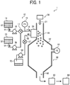
- FIG. 1 is a cross-sectional view illustrating the entirety of a toner production apparatus, which is a particulate material production apparatus according to an embodiment.
- a toner production apparatus 1 illustrated in FIG. 1 includes a droplet ejecting unit 10, a drying and collecting unit 60 serving as a solidifying device, and a gas feeder 30 (such as air feeder) as main components.
- the droplet ejecting unit 10 includes a droplet ejector 20 serving as a droplet ejecting device and including multiple droplet ejecting heads to eject droplets of a toner composition liquid (i.e., a liquid including a composition, hereinafter sometimes referred to as a composition liquid) in a liquid column resonance chamber 22 (illustrated in FIG. 2 ) in a horizontal direction.
- a toner composition liquid i.e., a liquid including a composition, hereinafter sometimes referred to as a composition liquid
- the droplet ejector 20 is not limited to a device using a liquid column resonance standing wave as long as the device can eject droplets of a composition liquid from nozzles by changing the internal pressure in a liquid chamber.
- the gas feeder 30 (hereinafter referred to as an airflow supplier) generates airflow to feed and dry the droplets ejected by the droplet ejector 20.
- the airflow supplier 30 is not particularly limited as long as the device can generate a flowing gas having a desired flow rate and a desired volume.
- the droplet ejector used for the droplet ejector 20 of the particulate material production apparatus is not particularly limited, and any known droplet ejectors can be used.
- Specific examples of the droplet ejector include one-fluid type nozzles, two-fluid type nozzles, membrane oscillation type ejectors, Rayleigh fission type ejectors, liquid vibration type ejectors, and liquid column resonance type ejectors.
- vibration is applied to a composition liquid of the particulate material in a liquid column resonance chamber having multiple nozzles to form a standing wave.
- the nozzles are located at a location corresponding to an anitnode of the standing wave, and the composition liquid is ejected from the nozzles as droplets.
- One of these droplet ejectors is preferably used for the droplet ejector of the particulate material production apparatus.
- the droplet ejecting unit 10 includes a toner composition liquid container 13 (i.e., a raw material container), which stores a toner composition liquid 12.
- the toner composition liquid 12 is a liquid in which components constituting a toner composition are dissolved or dispersed in a solvent and which forms particles of the toner when ejected and dried. The toner components will be described later in detail.
- the toner composition liquid 12 stored in the toner composition liquid container 13 is supplied to the droplet ejector 20 by a toner composition liquid supplying device 16 (i.e., particulate material composition liquid supplying device) through supply tubes 14 and 18 and a switching device 17.
- a toner composition liquid supplying device 16 i.e., particulate material composition liquid supplying device
- the particulate material production apparatus 1 further includes a cleaner to clean the nozzles of the droplet ejector 20.
- the cleaner includes a cleaning liquid container 53, which stores a cleaning liquid 52 (i.e., second cleaning liquid).
- the second cleaning liquid 52 is the same as or different from a first cleaning liquid 44 (illustrated in FIG. 14 ).
- the cleaning liquid 52 is preferably a solvent which is the same kind of solvent as used for the toner composition liquid, but is not limited thereto as long as the solvent does not cause a change in the toner composition liquid such as reaction with the toner components, and agglomeration of the components dispersed in the toner composition liquid.
- the cleaning liquid 52 stored in the cleaning liquid container 53 is supplied to the droplet ejector 20 by a second cleaning liquid supplying device 56 through a supply tube 54, the switching device 17, and the supply tube 18.
- the switching device 17 performs switching such that the liquid supplied to the droplet ejector 20 is changed from the toner composition liquid 12 to the cleaning liquid 52 or vice versa.
- the liquid (the toner composition liquid or the cleaning liquid) is discharged from the droplet ejector 20
- the liquid is fed to a waste liquid container 50 by a discharging device 59 through a discharge tube 58 and a valve 57 to control discharging of the liquid from the droplet ejector 20.
- the switching device 17 achieves a state in which the toner composition liquid can be fed to the droplet ejector 20 from the toner composition liquid container 13, and the valve 57 achieves a closed state in which the liquid is not fed from the droplet ejector 20 to the waste liquid container 50 unless otherwise specified.
- a pressure gauge 19 is provided on the supply tube 18 to measure an inner pressure PI of the supply tube.
- another pressure gauge 61 is provided on the drying and collecting unit 60 to measure an inner pressure P2 of the drying and collecting unit.
- the pressure (PI) of the liquid (e.g., toner composition liquid 12) supplied to the droplet ejector 20 through the supply tube 18 is measured with the pressure gauge 19, and the pressure (P2) in the drying and collecting unit 60 is measured with the pressure gauge 61, to control the pressures PI and P2.
- the toner composition liquid may drip from the nozzles of the droplet ejecting heads.
- the pressure PI when the pressure PI is lower than the pressure P2, air may enter into the droplet ejecting heads from the drying and collecting unit 60, thereby making it impossible to eject droplets of the toner composition liquid 12 from the nozzles. Therefore, it is preferable that the pressures P1 and P2 are substantially the same.
- the toner composition liquid supplying device 16, the second cleaning liquid supplying device 56, and the discharging device 59 are not particularly limited, and any known devices capable of feeding a liquid while performing pressure controlling can be used therefor. Specific examples thereof include syringe pumps, tube pumps, and gear pumps. In addition, instead of such mechanical liquid feeding devices, a method in which the toner composition liquid container 13, the cleaning liquid container 53 and the waste liquid container 50 are closed while controlling the pressures in the containers can also be used.
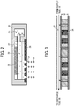
- FIG. 2 is a cross-sectional view illustrating the droplet ejecting head (i.e., part of the droplet ejector 20).
- the droplet ejecting head of the droplet ejector 20 includes a common liquid passage 21 and the liquid column resonance chamber 22.
- the liquid column resonance chamber 22 is communicated with the common liquid passage 21, which is provided on one of end walls in the longitudinal direction of the liquid column resonance chamber.
- the liquid column resonance chamber 22 has another wall connected with the end walls and having droplet ejection nozzles 24 to eject droplets 23 of the toner composition liquid 12, and a vibrator 25 generating high-frequency vibration to form a liquid column resonance wave in the liquid column resonance chamber 22.
- the vibrator 25 is connected with a high-frequency power source.
- the drying and collecting unit 60 includes a chamber 62, a toner collector 63, and a toner container 64.
- a carrier gas (such as air) 31 (hereinafter sometimes referred to as carrier air or airflow) is downwardly fed to the chamber 62 by a gas feeder 30 (hereinafter referred to as an air feeder) such as a blower.
- the flow direction of the carrier air 31 is substantially perpendicular to the ejection direction of droplets ejected by the droplet ejector 20.
- the droplet flight velocity can be increased, thereby making it possible to prevent uniting of the ejected droplets.
- the velocity of the droplets 23 is increased, thereby preventing the velocity of the droplets from being decreased due to friction between the droplets and air.
- the flight direction of the droplets is changed by the carrier air 31, the distance between the droplets is increased. Therefore, occurrence of the droplet uniting problem can be prevented.
- a method in which a blower is provided on an upper portion of the chamber 62 as the airflow supplier 30 (illustrated in FIG. 1 ) to pressure-feed air downward a method in which air is sucked from the toner collector 63, or the like method can be used.
- Swirling airflow swirling around a vertical axis is formed in the toner collector 63 by a swirling airflow generator.
- the toner particles collected by the toner collector 63 are fed to the toner container 64 through a toner collection tube connecting the chamber 62 with the toner container 64 through the toner collector 63.
- the droplets 23 of the toner composition liquid 12 i.e., liquid toner particles
- the droplets 23 of the toner composition liquid 12 i.e., liquid toner particles
- the droplets 23 of the toner composition liquid 12 i.e., liquid toner particles
- the droplets 23 of the toner composition liquid 12 i.e., liquid toner particles
- the solid toner particles are collected by the toner collector 63, and then stored in the toner container 64.
- the toner particles stored in the toner container 64 may be subjected to an additional drying treatment if desired.
- the toner composition liquid 12 contained in the toner composition liquid container 13 is fed by the toner composition liquid supplying device 16 to the common liquid passage 21 of the droplet ejector 20 (illustrated in FIGS. 2 and 3 ) through the supply tubes 14 and 18, so that the toner composition liquid is supplied to the liquid column resonance chambers 22 of the droplet ejecting heads of the droplet ejector 20.
- a pressure distribution is caused by a liquid column resonance standing wave generated by the vibrator 25.
- droplets 23 of the toner composition liquid 12 are ejected from the droplet ejection nozzles 24, which are arranged at a location of the liquid column resonance chamber 22 corresponding to an antinode (i.e., maximum amplitude point) of the liquid column resonance standing wave, at which pressure largely fluctuates.
- the antinode of a standing wave means an area of the standing wave other than an area of a wave node of the standing wave. It is preferable that at the area the standing wave has a large amplitude (i.e., a large pressure fluctuation) sufficient to eject droplets, and it is more preferable that the area is present in a region (hereinafter sometimes referred to as an antinode region) in which the maximum amplitude point of the pressure standing wave (i.e., the wave node of the velocity standing wave) is the center of the region and which has a length (width) of ⁇ 1/4 of the wavelength of the standing wave on both sides of the center.
- an antinode region in which the maximum amplitude point of the pressure standing wave (i.e., the wave node of the velocity standing wave) is the center of the region and which has a length (width) of ⁇ 1/4 of the wavelength of the standing wave on both sides of the center.
- droplets ejected from the nozzles have substantially the same particle size.
- droplets can be efficiently produced and chance of occurrence of a nozzle clogging problem in that the nozzles are clogged with the toner composition liquid can be reduced.
- the liquid column resonance chamber 22 is replenished with the toner composition liquid 12.
- the flow rate of the toner composition liquid flowing through the common liquid passage 21 increases so as to be the normal flow rate, and feeding of the toner composition liquid from the container 13 to the droplet ejector 20 through the supply tubes 14 and 18 is normalized.
- the toner composition liquid feeding pressure measured with the pressure gauge 19 is preferably from -2 to +2kPa, and the pressure is adjusted by the toner composition liquid supplying device 16. Even when the toner composition liquid feeding pressure is a small negative pressure, the liquid can be supplied to the droplet ejector 20 due to the voluntary liquid supply principle mentioned above. When the liquid feeding pressure is lower than -2kPa, air bubbles tend to be included in the chamber 22, resulting occurrence of non-ejection of droplets.
- the toner composition liquid feeding pressure is higher than +2kPa, the toner composition liquid tends to exude from the nozzles 24, resulting in occurrence of a problem in that the nozzles are clogged with a dried material of the liquid, thereby causing unstable droplet ejection.
- the cleaning liquid 52 is supplied, the liquid feeding pressure is not limited thereto.
- the liquid column resonance chamber 22 is preferably constituted of frames, which are connected with each other and which are made of a material having a high rigidity (such as metals, ceramics and silicon) such that the resonance frequency of the toner composition liquid in the liquid column resonance chamber 22 is not affected by the frames.
- a length L between two opposed longitudinal end walls of the liquid column resonance chamber 22 is determined based on the liquid column resonance principle mentioned below.
- a width W (illustrated in FIG. 3 ) of the liquid column resonance chamber 22 is preferably less than 1/2 of the length L so as not to apply an extra frequency, by which the liquid column resonance is influenced.
- each of the liquid resonance chambers in one droplet ejector 20 is preferably from 100 to 2,000 so that the toner production apparatus has a good combination of productivity and operability.
- each of the liquid resonance chambers is connected with the common liquid passage 21, i.e., the common liquid passage 21 is connected with multiple liquid column resonance chambers 22, and therefore the toner composition liquid can be supplied to each liquid resonance chamber. Since the common liquid passage 21 is connected with the discharge tube 58, the liquid in the droplet ejector 20 can be discharged if desired.
- the vibrator 25 of the droplet ejector 20 is not particularly limited as long as the vibrator can vibrate (operate) at a predetermined frequency, but a material in which a piezoelectric material is laminated to an elastic plate 27 is preferably used.
- the elastic plate 27 prevents the piezoelectric material form being contacted with the toner composition liquid, and constitutes part of the wall of the liquid column resonance chamber 22.
- Specific examples of the materials for use as the piezoelectric material include piezoelectric ceramics such as lead zirconate titanate (PZT). However, in general displacement of such a material is small, and therefore laminated materials in which several piezoelectric materials are laminated are typically used.
- the vibrator 25 is preferably arranged in each of the liquid column resonance chambers 22 to control vibration of the chamber.
- the vibrator 25 preferably has a structure such that a block of a vibrating member is set in the entirety of the liquid column resonance chambers while partially cut so that the vibrating member is arranged in each liquid column resonance chamber and vibration of each liquid column resonance chamber can be separately controlled via the elastic plate 27.
- the diameter of each of the droplet ejection nozzles 24 is preferably from 1 ⁇ m to 40 ⁇ m.
- the diameter is less than 1 ⁇ m, the diameter of ejected droplets becomes too small, and therefore there is a case where toner particles having a desired particle diameter is not produced.
- the toner composition liquid includes a particulate material, the nozzle clogging problem is often caused, thereby deteriorating the productivity.
- the diameter is greater than 40 ⁇ m, the diameter of ejected droplets becomes too large.
- the toner composition liquid has to have a low solid content (i.e., the toner composition liquid has to include a large amount of solvent), and a large amount of energy is used for drying the ejected droplets, resulting in deterioration of productivity and increase of production costs.
- the diameter of the nozzles 24 is from 6 ⁇ m to 12 ⁇ m, it is possible to form nozzles with small diameter variation, thereby enhancing the productivity of the toner.
- liquid column resonance frequency changes depending on the arrangement of the droplet ejection nozzles 24, it is preferable to properly determine the liquid column resonance frequency by checking whether desired droplets are ejected from the nozzles 24.
- the nozzles 24 are through-holes formed in a nozzle plate 26.
- the shape of the through-holes is not particularly limited.
- the nozzles can have a shape such that the diameter of the nozzles decreases in a direction of from the inner surface of the nozzle plate 26 contacting the toner composition liquid to the outer surface of the nozzle plate while the inner surface of the nozzle is rounded, or a shape such that the diameter decreases in a direction of from the inner surface of the nozzle plate 26 contacting the toner composition liquid to the outer surface of the nozzle plate at a certain rate (i.e., the inner surface of the nozzle is tapered at a certain angle).
- a certain rate i.e., the inner surface of the nozzle is tapered at a certain angle
- the surface of the nozzle plate 26, which includes the nozzles 24, is preferably subjected to a liquid repellent treatment so that wetting of the surface of the nozzle plate with the toner composition liquid can be controlled, and thereby droplet ejection stability can be enhanced.
- the liquid repellent treatment will be described in detail.
- the entire surface of the nozzle plate 26 preferably has a SiO 2 layer 28 and a liquid repelling layer 29 located on the SiO 2 layer.
- the liquid repelling layer includes a material having a linear perfluoroalkyl group having the following formula (1) or (2) or an alkyl group having a sixalane bond (-SiO-) with a perfluoropolyether group and having the following formula (3) or (4): CF 3 (CF 2 ) n -Si(OR) 3 (1), CF 3 (CF 2 ) n -Si(OR 1 ) 2 R 2 (2), CF 3 (OCF 2 -CF 2 CF 2 ) n -X-Si(OR) 3 (3), and CF 3 (OCF 2 -CF 2 CF 2 ) n -X-Si(OR 1 ) 2 R 2 (4).
- CF 3 (CF 2 ) n -Si(OR) 3 (1) CF 3 (CF 2 ) n -Si(OR 1 ) 2 R 2 (2), CF 3 (OCF 2 -CF 2 CF 2 ) n -X-Si(OR) 3 (3),
- X is not particularly limited.
- each of R, R 1 , and R 2 is alkyl group (a binding site of a SiO 2 layer), and the more the number of the binding sites, the stronger the binding force of the repelling layer with the SiO 2 layer. Therefore, the number of the binding sites is preferably three.
- the perfluoroalkyl group of the material is present on the surface of the liquid repelling layer so as to be contacted with the particulate material composition liquid (i.e., so as to repel the particulate material composition liquid).
- the liquid repelling layer can be formed by a vacuum deposition method, which is described layer, but is not limited thereto.
- a vacuum deposition method which is described layer, but is not limited thereto.
- spray coating methods, spin coating methods, dip coating methods, and printing methods can also be used.
- the solvent include fluorine-containing solvents such as perfluorohexane, perfluoromethylcyclohexane, and FLUORINERT FC-72 (from Sumitomo 3M Ltd.).
- a SiO 2 layer with a thickness of a few nanometers to tens of nanometers is formed on the liquid ejection surface side by radio frequency sputtering (i.e., first step).
- the layer is subjected to a degreasing/washing treatment (second step), and the SiO 2 layer is then subjected to vacuum vapor deposition using such a fluorine-containing material as mentioned above (third step), followed by a calcination treatment or a polymerization treatment (fourth step).
- a liquid repelling layer can be formed.
- the thickness of the liquid repelling layer can be controlled by controlling the vacuum deposition time, and is preferably not less than 10nm. When the thickness is less than 10nm, the layer tends to be gradually peeled after long repeated use.
- the thus formed liquid repelling layer preferably has a contact angle of not less than 40 degree against the toner composition liquid used so that the layer has good liquid repelling property.
- the length between the end wall of the liquid column resonance chamber 22 to the other end wall closer to the common liquid passage 21 is L, and the end wall closer to the common liquid passage has a height of h1 while the opening communicating the liquid column resonance chamber 22 with the common liquid passage 21 has a height of h2.
- the height h1 is twice the height h2 (e.g., h1 is about 80 ⁇ m, and h2 is about 40 ⁇ m) and it is provided that both the end walls are equivalent to fixed ends (i.e., the chamber 22 has two fixed ends)
- FIGS. 4A-4D illustrate standing waves (in a resonance mode) of velocity fluctuation and pressure fluctuation when N is 1, 2 or 3.
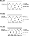
- FIGS. 5A-5C illustrate standing waves (in a resonance mode) of velocity fluctuation and pressure fluctuation when N is 4 or 5.
- each of the waves is a compression wave (longitudinal wave), but is generally illustrated as the waves in FIGS. 4 and 5 .
- a velocity standing wave is illustrated by a solid line
- a pressure standing wave is illustrated by a dotted line.
- the frequency of the velocity distribution becomes zero at the closed end, and has a maximum value at the open end.
- the length of the liquid column resonance chamber is L
- the wavelength of resonance is ⁇
- N is 1, 2, 3, 4 or 5
- both the cases i.e., opened or closed state
- the states of the ends are determined depending on the conditions of the openings of the droplet ejection nozzles 24 and the opening connecting the liquid column resonance chamber 22 with the common liquid passage 21.
- an open end means an end at which the moving velocity of a medium (liquid) becomes zero, and the pressure is maximized.
- the moving velocity of a medium is zero.
- the closed end is considered to be a hard wall in acoustics, and reflection of a wave is caused.
- the shape of the standing waves is changed depending on the number of the droplet ejection nozzles 24 and the positions of the nozzles, and therefore the most efficient frequency f may be slightly different from that obtained from equation (3).
- the drive frequency by properly adjusting the drive frequency, stable ejection conditions can be established.
- the acoustic velocity c is 1,200 m/s in the liquid
- the length L of the chamber is 1.85mm
- both the ends are closed ends (walls)
- the most efficient frequency f is determined as 324 kHz from equation (2).
- the most efficient frequency f is determined as 648 kHz from equation (2). In the latter case, higher-degree resonance than in the former case can be used.
- the liquid column resonance chamber 22 of the droplet ejector 20 illustrated in FIGS. 1 and 2 is equivalent to a chamber having two closed ends. It is preferable that the wall having the droplet ejection nozzles 24 is an acoustically soft wall (due to the openings of the nozzles) to increase the most efficient frequency.
- the liquid column resonance chamber 22 is not limited thereto, and can have two open ends. In this regard, the influence of the openings of the droplet ejection nozzles is such that the acoustic impedance is decreased thereby, and particularly the compliance is increased thereby. Therefore, the liquid column resonance chamber 22 preferably has such a structure as illustrated in FIG.
- the drive frequency is preferably determined depending on factors such as the number of openings (nozzles), the positions of the openings and the cross-sectional shape of the openings. For example, when the number of openings is increased, the fixed end of the liquid column resonance chamber is loosely bounded so as to be similar to an open end, and the generated standing wave becomes similar to a standing wave formed in a chamber having one open end, resulting in increase of the drive frequency.
- the real standing wave has a shorter wavelength, and therefore the frequency of the wave becomes higher than the drive frequency.
- a voltage is applied to the vibrator to generate the thus determined drive frequency (most efficient drive frequency)
- the vibrator is deformed and thereby a resonance standing wave can be generated most efficiently.
- a resonance standing wave can also be generated at a drive frequency in the vicinity of the most efficient drive frequency.
- droplets of the toner composition liquid 12 can be ejected from the nozzles by liquid column resonance caused by vibrating the vibrator using a drive wave including, as a main component, a drive frequency f in the range represented by the following relationships (4) and (5): N ⁇ c / 4 / L ⁇ f ⁇ N ⁇ c / 4 Le and N ⁇ c / 4 / L ⁇ f ⁇ N + 1 ⁇ c / 4 Le
- the ratio (Le/L) of the length between the end wall of the chamber closer to the common liquid supply 21 and the nozzle closest to the end wall Le to the length of the liquid column resonance chamber 22 in the longitudinal direction thereof L is preferably greater than 0.6.
- liquid column resonance standing wave of pressure is formed in the liquid column resonance chamber 22 illustrated in FIG. 2 , thereby continuously ejecting droplets of the toner composition liquid from the liquid ejection nozzles 24 of the liquid column resonance chamber.
- the liquid ejection nozzles 24 are formed on a position, at which the pressure of the standing wave varies most largely, because the droplet ejecting efficiency is enhanced, and thereby the liquid ejector 20 can be driven at a low voltage.
- the liquid column resonance chamber 22 may have only one liquid ejection nozzle, it is preferable for the chamber to have multiple liquid ejection nozzles, preferably from 2 to 100 nozzles, to enhance the productivity of the product (toner).
- the number of nozzles is greater than 100, the voltage applied to the vibrator 25 has to be increased in order to form droplets having a desired particle diameter.
- the piezoelectric material serving as the vibrator tends to operate unstably.
- the distance between two adjacent nozzles is preferably not less than 20 ⁇ m and less than the length L of the liquid column resonance chamber 22. When the distance between two adjacent nozzles is less than 20 ⁇ m, chance of collision of droplets ejected from the two adjacent nozzles is increased, thereby forming united particles, resulting in deterioration of the particle diameter distribution of the resultant toner.
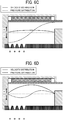
- a solid line represents the velocity distribution of the toner composition liquid 12 at any position of from the fixed end to the other end closer to the common liquid passage 21 (illustrated in FIG. 2 ).
- the toner composition liquid 12 flows from the common liquid passage 21 toward the liquid column resonance chamber 22.
- the toner composition liquid 12 flows in the opposite direction.
- a dotted line represents the pressure distribution of the toner composition liquid 12 at any position of from the fixed end to the other end closer to the common liquid passage 21.
- the pressure in the chamber 22 is higher than atmospheric pressure (i.e., the pressure is a positive pressure).
- the pressure in the chamber 22 is a positive pressure
- the pressure in a negative (-) region the pressure is lower than atmospheric pressure (i.e., the pressure is a negative pressure).
- the pressure in the chamber 22 is a positive pressure
- a downward pressure is applied to the toner composition liquid 12 in FIG. 6 .
- an upward pressure is applied to the toner composition liquid in FIG. 7 .
- the height (h1 in FIG. 2 ) of the frame (fixed end) of the liquid column resonance chamber 22 is not less than about twice the height (h2 in FIG. 2 ) of the opening connecting the chamber 22 with the common liquid passage 21, and therefore temporal changes of the velocity distribution curve and the pressure distribution curve are illustrated in FIGS. 6A-6D while assuming that the liquid column resonance chamber 22 has two fixed ends.
- FIG. 6A illustrates the pressure waveform and the velocity waveform in the liquid column resonance chamber 22 just after droplets are ejected from the droplet ejection nozzles 24, and FIG. 6B illustrates the pressure waveform and the velocity waveform in the liquid column resonance chamber 22 at a time when the toner composition liquid is sucked just after droplets are ejected.
- the pressure in a portion of the toner composition liquid 12 above the nozzles 24 in the liquid column resonance chamber 22 is maximized.
- the flow direction of the toner composition liquid 12 in the liquid column resonance chamber 22 is the direction of from the nozzles 24 to the common liquid passage 21 and the velocity thereof is low.
- the positive pressure in the vicinity of the nozzles 24 is decreased, so that the pressure is changed toward a negative region (pressure).
- the flow direction of the toner composition liquid 12 is not changed, but the velocity of the toner composition liquid is maximized, thereby ejecting droplets of the toner composition liquid.
- the pressure in the vicinity of the droplet ejection nozzles 24 is minimized (i.e., maximized in the negative region) as illustrated in FIG. 6C .
- feeding of the toner composition liquid 12 to the liquid column resonance chamber 22 from the common liquid passage 21 is started.
- the negative pressure in the vicinity of the nozzles 24 is decreased, so that the pressure is changed toward a positive pressure.
- the liquid filling operation is completed.
- the positive pressure in the liquid column resonance chamber 22 is maximized as illustrated in FIG. 6A , and then the droplets 23 of the toner composition liquid 12 are ejected as illustrated in FIG. 6B .
- a liquid column resonance standing wave is formed in the liquid column resonance chamber 22 by driving the vibrator with a high frequency wave, and in addition the droplet ejection nozzles 24 are arranged at a location corresponding to the antinode of the standing wave at which the pressure varies most largely, the droplets 23 of the toner composition liquid 12 can be continuously ejected from the droplet ejection nozzles 24 according to the cycle of the antinode.
- a sine wave having a frequency of 340 kHz is used to eject droplets of a toner composition liquid.
- FIG. 7 is a photograph, which is taken by using a laser shadowgraphy method and which shows droplets of the toner composition liquid ejected from the four nozzles. It can be understood from FIG. 7 that droplets having substantially the same particle diameter can be ejected from the four nozzles at substantially the same velocity.
- FIG. 8 is a graph showing the velocity of droplets ejected from the first to fourth nozzles when using a sine wave with a drive frequency in a range of from 290 kHz to 395 kHz. It can be understood from FIG. 8 that at the frequency of 340 kHz, the velocities of droplets ejected from the first to fourth nozzles are substantially the same while the velocities are maximized. Namely, it could be confirmed that droplets of the toner composition liquid are evenly ejected from the antinode of the liquid column resonance standing wave when the second mode is used (i.e., when the liquid column resonance frequency is 340 kHz).
- the velocities of droplets ejected from the first to fourth nozzles when the first mode is used are shown on the left side of the graph ( FIG. 8 ). It can also be understood from FIG. 8 that droplets are not ejected at frequencies between the first mode (130 kHz) and the second mode (340 kHz). This frequency characteristic is specific to liquid column resonance standing waves, and therefore it was confirmed that liquid column resonance occurs in the chamber 22.
- the particle diameter distribution of a toner obtained by drying droplets including such a united particle is illustrated in FIG. 9 .
- the united droplet since such a united droplet receives higher air resistance than a single droplet, the united droplet tends to be further united with another droplet, thereby forming united droplets in which three or more droplets are united.
- the resultant toner has a wider particle diameter distribution.
- FIG. 10 is a graph showing the particle diameter distribution of a toner obtained by drying droplets, which mainly include single droplets and which hardly include united droplets.
- the toner obtained by drying droplets including united particles has such a particle diameter distribution as illustrated in FIG. 9 . It is clear from FIG. 9 that the toner includes united particles such as united two, three, four or more particles.
- the particle diameter distribution of toner is determined using a flow particle image analyzer FPIA-3000 from Sysmex Corp.
- the united toner particles serve as large toner particles, and are not preferable.
- These united toner particles are typically formed when single droplets, which are dried to a certain extent, are contacted with each other. Specifically, a semi-dried single droplet, which is dried to a certain extent, is adhered to a wall of the chamber 62 or a feed pipe, and then another semi-dried single droplet is adhered thereto. After the united droplets are dried, the resultant united particles are separated from the chamber or the feed pipe, resulting in formation of united toner particles. In order to prevent formation of such united toner particles, it is preferable to quickly dry the ejected droplets or to control airflow in the toner production apparatus to prevent the ejected droplets from being adhered to a chamber or a feed pipe.
- the particle diameter distribution of a particulate material is typically represented by a ratio (Dv/Dn) of the volume average particle diameter (Dv) to the number average particle diameter (Dn) of the particulate material.
- the ratio (Dv/Dn) is 1.0 at minimum. In this case, all the particles have the same particle diameter. As the ratio (Dv/Dn) increases, the particulate material has a wider particle diameter distribution.
- Toner prepared by a pulverization method typically has a ratio (Dv/Dn) of from 1.15 to 1.25, and toner prepared by a polymerization method typically has a ratio (Dv/Dn) of from 1.10 to 1.15.
- the toner prepared by the toner production method of the present invention has a ratio (Dv/Dn) of not greater than 1.15, high quality toner images can be produced.
- the ratio (Dv/Dn) is more preferably not greater than 1.10.
- the Dv/Dn ratio of the toner is preferably not greater than 1.15, and more preferably not greater than 1.10.
- the droplet ejector 20 (illustrated in FIG. 1 ) is arranged at a location between the chamber 62 and the entrance of the carrier air 31 in such a manner that the droplet ejection direction is substantially perpendicular to the flow direction of the carrier air 31.
- the present inventors observe behavior of ejected droplets in a range of from the nozzles to a position apart from the nozzles by 2mm using a laser shadowgraphy method, which has not been performed until now. As a result of the observation, it was found that uniting of droplets is caused even in such a near-nozzle range.
- the droplet ejector 20 is arranged so as to eject droplets in a direction perpendicular to the flow direction of the carrier air 31. As a result, it was confirmed that the number of united particles can be dramatically reduced by this method.
- flight direction of the droplets ejected from the droplet ejector 20 in substantially the horizontal direction is changed by the carrier air 31, whose flow direction is perpendicular to the droplet ejection direction, so as to be the same as the flow direction of the carrier air 31.
- the droplet flight velocity can be maintained or increased, thereby making it possible to reduce chance of uniting of the droplets. Therefore, a toner having an extremely sharp particle diameter distribution can be provided.
- the carrier air 31 preferably has such a velocity as to change the moving direction of the ejected droplets 23, and the velocity is preferably not less than 7m/s, and more preferably from 8 to 15 m/s.
- the velocity is lower than 7m/s, there is a case where two adjacent droplets are contacted and united before the moving direction of the droplets is changed by the carrier air 31, thereby widening the particle diameter distribution of the resultant toner.
- the velocity is higher than 16m/s, there is a case where a fine droplet is released from an ejected droplet, resulting in formation of fine droplets, thereby widening the particle diameter distribution of the resultant toner.
- the initial velocity (V 0 ) of the droplets 23 preferably satisfies the following relationship:
- the distance between two adjacent droplets is shortened, and therefore two adjacent droplets are easily contacted and united before the moving direction of the droplets is changed by the carrier air 31.
- the diameter of the ejected droplet 23 and the ejection velocity can be adjusted by adjusting the diameter of the nozzles, the drive frequency, and the voltage applied to the vibrator 25.
- the droplet ejector 20 ejects droplets 23 of the toner composition liquid in substantially a horizontal direction, but the droplet ejection direction is not limited to the horizontal direction.
- the droplet ejection angle can be set to a proper angle.
- a method in which a blower is provided on an upper portion of an entrance (airflow passage) 65 of the chamber 62 to feed air downward, or a method in which air is sucked from an exit 66 of the chamber 62 can be used.
- Specific examples of the toner collector 63 include cyclones, bag filters, and the like.
- the airflow 31 is not particularly limited as long as the airflow 31 can prevent uniting of ejected droplets, and may laminar flow, swirling flow, or turbulent flow.
- the gaseous material constituting the carrier gas 31 is not particularly limited, and is typically air or an inert gas such as a nitrogen gas.
- the ejected droplets are preferably dried as quickly as possible. Therefore, the content of the vapor of the solvent, which is included in the droplets, in the chamber 62 is preferably as low as possible.
- the temperature of the carrier air 31 is preferably adjustable, and it is preferable that the temperature of the carrier air 31 is not changed during a toner production process. It is possible to provide a device for changing the conditions of the airflow 31 in the chamber 62.
- the airflow 31 may be used not only for preventing the ejected droplets from being united but also for preventing the ejected droplets from being adhered to an inner wall of the chamber 62.
- the toner particles may be subjected to a second drying treatment.
- Any known drying methods such as fluidized bed drying and vacuum drying can be used for the second drying treatment.
- an organic solvent remains in the toner particles in a relatively large amount, not only toner properties such as high temperature preservability, fixability and charging property deteriorate, but also a problem in that the organic solvent is evaporated when toner images are fixed, and therefore the vapor of the organic solvent adversely affects the users, the image forming apparatus, and the peripheral machines is caused. Therefore, it is preferable to sufficiently dry the toner particles.
- the method for cleaning a droplet ejecting head is a non-contact cleaning method using a non-contact cleaner and a cleaning liquid.
- a non-contact method By cleaning the nozzle plate using a non-contact method, chance of occurrence of problems caused by a contact method such as a wiping method used for cleaning inkjet recording heads such that the liquid repelling effect of the liquid repelling layer formed on the nozzle plate is deteriorated by wiping the nozzle plate, and the nozzle plate is degraded by wiping can be reduced.
- FIG. 13 is a schematic cross-sectional view illustrating a droplet ejector including a cleaner.
- the droplet ejector 20 has the deposit (smudge) 40 on a surface of the nozzle plate in the vicinity of the nozzles 24.
- a space in the vicinity of the nozzles 24 in the airflow passage 65 is isolated by an isolating device to form a cleaning space while input of a driving signal for driving the droplet ejector is stopped, so that the cleaning space can be filled with a cleaning liquid.
- a driving signal for driving the droplet ejector is stopped, so that the cleaning space can be filled with a cleaning liquid.
- a shutter 41 serves as the isolating device (i.e., cleaning space forming device) to form the cleaning space, which is to be filled with a cleaning liquid (a first cleaning liquid 44), in the airflow passage 65 of the chamber 62.
- a cleaning liquid 44 is fed from a tank (not shown) to the cleaning space by a cleaning liquid pump 42 through a pipe 43 to fill the cleaning space with the cleaning liquid 44.
- the cleaning liquid pump serves as a first cleaning liquid supplying device.
- the cleaning liquid 44 is vibrated by a cleaning liquid vibrator 45 to dissolve the deposit 40 or to separate the deposit 40 from the nozzle plate, resulting in cleaning of the nozzle surface.
- the cleaning liquid 44 After vibrating the cleaning liquid 44 (i.e., after the deposit 40 is removed from the nozzle surface), the cleaning liquid is discharged from the cleaning space by the cleaning liquid pump 42 through the pipe 43, and the shutter 41 is returned to the original position. Thus, the cleaning operation is completed.
- the deposit (smudge) 40 to be removed by the non-contact nozzle cleaning method of this disclosure is a dried material of the toner composition liquid formed on the nozzle plate and the vicinity of the nozzles, and the deposits are present over a relatively wide range.
- a space in the vicinity of the nozzles 24 in the airflow passage 65 is isolated by an isolating device to form a cleaning space to be filled with the cleaning liquid. Therefore, the area of the droplet ejector 20 contacted with the cleaning liquid 44 can be cleaned.
- FIG. 16A illustrates an inner surface of the chamber 62 on which the SiO 2 layer 28 and the liquid repelling layer 29 are formed.
- the first cleaning liquid 44 (illustrated in FIG. 14 ) to be contained in the cleaning space in the chamber 62 is preferably a solvent which can dissolve the toner composition to enhance the cleaning effect.
- the solvent does not cause a chemical reaction with the toner composition liquid and the cleaning liquid supplied to the droplet ejector 20 or agglomeration of the dispersed components in the toner composition liquid, or does not change the property or formulation of the toner composition liquid. Therefore, it is preferable that the solvent used for the toner composition liquid, the cleaning liquid supplied to the droplet ejector 20, and the cleaning liquid to be contained in the cleaning space are the same kind of solvent.
- the solvent used for the cleaning liquid is not limited thereto.
- solvents can be used for the cleaning liquid as long as the above-mentioned conditions are satisfied.
- ethyl acetate is used as the solvent of the toner composition liquid.
- solvents such as ethyl acetate, acetone, methyl ethyl ketone (MEK), and tetrahydrofuran (THF) can be used for the cleaning liquid.
- the cleaning effect can be further enhanced.
- the higher the temperature of the cleaning liquid the better the cleaning effect.
- the temperature is higher than the boiling point of the solvent used for the toner composition liquid, a problem in that the solvent in the toner composition liquid evaporates, thereby making it impossible to eject droplets of the toner composition liquid due to bubbles formed in the toner composition liquid by evaporation of the solvent is caused.
- the temperature is higher than the melting point of a wax dispersed in the toner composition liquid, the dispersed wax particles are partially melted, resulting in change of the properties of the toner composition liquid, thereby adversely affecting the ejection stability of the toner composition liquid. Therefore, the temperature of the cleaning liquid preferably falls in a range in which the properties of the toner composition liquid do not deteriorate.
- the isolating device to form a cleaning space in the vicinity of the nozzles is not particularly limited as long as the purpose (i.e., containing a cleaning liquid in the cleaning space without leaking) can be achieved.
- the isolating device is a slidable valve, but rotary valves, ball valves, and other valves can also be used.
- the cleaning space is formed by separating a part of the airflow passage using the shutter 41.
- the top surface of the shutter 41 preferably serves as a part of the inner wall of the chamber 62 (i.e., the top surface is located on the same plane as the inner wall of the chamber) when the shutter is opened (i.e., the cleaning operation is not performed) so that the airflow 31 is not turbulent when the toner composition liquid 12 is ejected from the nozzles 24.
- the cleaning liquid vibrator 45 is not particularly limited as long as the vibrator can operate (vibrate) at a predetermined frequency. It is preferable to provide an amplifier such as horns on the piezoelectric material. Piezoelectric ceramics such as lead zirconate titanate (PZT) can be preferably used for the piezoelectric material. In addition, popular Langevin ultrasonic vibrators can also be used.
- the drive frequency is preferably from 10 to 100kHz, and it is possible to use a combination of plural frequencies. In addition, it is possible to change the drive frequency with time in a cleaning operation to change the cleaning efficiency.
- the cleaning liquid vibrator 45 is set so as to be a part of the wall forming the cleaning space, and preferably faces the nozzles 24.
- the cleaning liquid 44 is vibrated with the vibrator 25 of the droplet ejector 20 via the toner composition liquid 12. Namely, by switching the drive frequency for the vibrator 25 to the drive frequency for cleaning, the toner composition liquid is strongly vibrated to transmit the vibration to the cleaning liquid 44 contacted with the toner composition liquid 12 at the nozzles 24.
- the cleaning method is determined depending on the degree or property of the smudges (such as deposit 40), and one or more steps in FIG. 15 can be omitted if unnecessary.
- the toner composition liquid is switched to a second cleaning liquid (step S102), so that pressure cleaning can be performed (step S103) without forming bubbles of a gas in the droplet ejecting head. Since no gas enters into the droplet ejecting head, the cleaning operation can be performed securely while preventing the toner composition liquid from drying. Therefore, occurrence of problems in that the chamber 22 is deformed, and the viscosity of the toner composition liquid increases, thereby deteriorating the droplet ejection performance of the droplet ejecting head can be prevented.
- the switching device 17 changes a liquid supply passage of from the toner composition liquid container 13 to the droplet ejector 20 to another liquid supply passage of from the cleaning liquid container 53 to the droplet ejector 20.
- the valve 57 is opened, the second cleaning liquid 52 in the cleaning liquid container 53 is supplied to the droplet ejector 20 by the second cleaning liquid supplying device 56. Therefore, the toner composition liquid in the droplet ejector 20 and the supply tube 18 is fed to the waste liquid container 50 while replaced with the second cleaning liquid 52.
- the shutter 41 is closed to form a cleaning space to be filled with the first cleaning liquid 44, which is the same as or different from the second cleaning liquid supplied to the droplet ejector 20, in the vicinity of the droplet ejector, and the first cleaning liquid 44 is supplied from a cleaning liquid tank (not shown) to the cleaning space by the cleaning liquid pump 42 through the pipe 43, thereby filling the cleaning space with the first cleaning liquid 44.
- the first cleaning liquid 44 is vibrated by the vibrator 45 to dissolve the smudges (such as deposit 40) or separate the smudges from nozzles and the nozzle plate.
- step S103 the valve 57 is closed in addition to the switching operation (step S102), and the second cleaning liquid 52 is continuously supplied to the droplet ejector 20, thereby increasing the pressure in the supply tube 18 which is measured with the pressure gauge 19.
- the second cleaning liquid is discharged from the nozzles 24, thereby removing a dried material of the toner composition liquid covering the nozzles while removing bubbles and foreign solid materials, which are present in the droplet ejecting head and which cause the nozzle clogging problem, from the head.
- the liquid feeding pressure can be measured by the pressure gauge 19 to be controlled.
- the proper liquid feeding pressure for the cleaning operation is determined depending on the diameter of the nozzles 24, and is preferably from 5 to 50kPa, and more preferably from 20 to 40kPa.
- the liquid feeding pressure is lower than 5kPa, the cleaning operation tends to be insufficiently performed.
- the liquid feeding pressure is higher than 50kPa, a problem in that the droplet ejector 20 is damaged tends to be caused while excessively consuming the cleaning liquid.
- step S104 a suction cleaning process is performed (step S104).
- step S104 the nozzle plate of the droplet ejecting head is dipped in the cleaning liquid while stopping feeding of the cleaning liquid by the second cleaning liquid supplying device 56, operating the discharging device 59, and opening the valve 57 so that the pressure in the discharge tube 58 is a negative pressure of -10kPa, thereby flowing the cleaning liquid (first cleaning liquid) from the cleaning space to the droplet ejecting head (i.e., flowing the cleaning liquid in a direction opposite to that in the pressure cleaning operation mentioned above).
- solid materials which are present in the droplet ejecting head and with which the nozzles are clogged can be removed.
- the toner composition liquid and the deposit 40 adhered to the outer surface of the nozzles can also be removed.
- the suction pressure of sucking the cleaning liquid can be measured by the pressure gauge 19 to be controlled.
- the proper suction pressure is determined depending on the diameter of the nozzles 24, and is preferably from -5 to -50kPa, and more preferably from -10 to -20kPa. When the suction pressure is lower than -5kPa (in absolute value), the cleaning operation tends to be insufficiently performed.
- the suction pressure is higher than -50kPa (in absolute value)
- the suction pressure is preferably not higher than -50kPa (in absolute value).
- the cleaning liquid in the vicinity of the droplet ejector 20 is discharged by the pump 42 and then a new first cleaning liquid is supplied to the cleaning space by the pump 42 so that the cleaning space is filled with the first cleaning liquid.
- This cleaning liquid changing operation may be performed plural times before starting the suction cleaning process.
- a second pressure cleaning process which is the same as the first pressure cleaning process (step S103) is performed (step S105).
- vibration of the first cleaning liquid 44 using the vibrator 45 is stopped, and then the first cleaning liquid 44 is discharged by the pump 42 through the pipe 43, followed by opening of the shutter 41.
- step S106 switching from the second cleaning liquid to the toner composition liquid is performed by the switching device 17 without allowing the droplet ejecting head to be empty (step S106), and then the droplet ejecting operation is restarted (step S107).
- step S106 the droplet ejecting head
- step S107 the droplet ejecting operation is restarted.
- bubbles are not included in the droplet ejecting head, and therefore droplets of the toner composition liquid can be stably ejected at a high droplet ejection rate even in the start of the droplet ejecting operation.
- this high droplet ejection rate can be maintained over a long period of time.
- the driving signal may be the same as the signal used for recording images, or a driving signal having a lower voltage than such a recording signal. It is confirmed that by using this method, the ejection stability of the droplet ejecting head can be dramatically enhanced.
- toner resultant particulate material
- the resultant particulate material hereinafter referred to as toner
- toner particles are not collected, or are collected in another container, followed by measuring the particle diameter thereof. If it is confirmed that the collected toner has no problem in quality, the toner can be used as the product.
- a droplet ejection method in which pressure distribution is formed using a liquid column resonance standing wave to eject droplets of a toner composition liquid from nozzles is used.
- the droplet ejection method is not limited thereto.
- toner will be described as an example of the particulate material to be produced by the particulate material production apparatus mentioned above.
- a toner having a sharp particle diameter distribution i.e., a toner like a monodisperse toner, can be produced.
- the toner preferably has a particle diameter distribution (i.e., Dv/Dn ratio) of from 1.00 to 1.15, and more preferably from 1.00 to 1.05.
- the volume average particle diameter (Dv) of the toner preferably falls in a range of from 1 ⁇ m to 20 ⁇ m, and more preferably from 3 ⁇ m to 10 ⁇ m.
- the toner components constituting the toner will be described. Initially, the toner composition liquid in which the toner components are dissolved or dispersed in a solvent will be described.
- the toner components can include a binder resin, a colorant, a release agent (such as waxes), and additives such as charge controlling agents.
- the toner composition liquid is typically prepared by a method including dissolving a binder resin such as styrene acrylic resins, polyester resins, polyol resins, and epoxy resins in a solvent, and dispersing a colorant in the resin solution while dispersing or dissolving therein a release agent, and optional additives.
- the thus prepared toner composition liquid is ejected from nozzles as droplets, and the droplets are dried, by using the toner production apparatus mentioned above to produce particles of the toner.
- the toner includes a binder resin, a colorant, and a release agent (such as waxes) as main components, and optionally includes other components such as charge controlling agents.
- the binder resin is not particularly limited, and any known resins for use in conventional toner can be used. Specific examples thereof include homopolymers and copolymers of vinyl compounds such as styrene compounds, acrylic compounds, and methacrylic compounds; polyester resins, polyol resins, phenolic resins, silicone resins, polyurethane resins, polyamide resins, furan resins, epoxy resins, xylene resins, terpene resins, coumarone-indene resins, polycarbonate resins, and petroleum resins.
- vinyl compounds such as styrene compounds, acrylic compounds, and methacrylic compounds
- polyester resins polyol resins, phenolic resins, silicone resins, polyurethane resins, polyamide resins, furan resins, epoxy resins, xylene resins, terpene resins, coumarone-indene resins, polycarbonate resins, and petroleum resins.
- the resin When a styrene-acrylic resin is used as a binder resin, the resin preferably has a molecular weight distribution such that when tetrahydrofuran(THF)-soluble components of the resin are subjected to gel permeation chromatography (GPC) to obtain a molecular weight distribution curve, the curve has at least one peak in a molecular weight range of from 3,000 to 50,000 (number average molecular weight) while having another peak at a molecular weight of not less than 100,000.
- GPC gel permeation chromatography
- the resin preferably has a property such that the THF-soluble components thereof preferably include components having a molecular weight of not greater than 100,000 in an amount of from 50 to 90%.
- the resin preferably has a main peak in a molecular weight range of from 5,000 to 30,000, and more preferably from 5,000 to 20,000.
- the vinyl polymer when a vinyl polymer (such as styrene-acrylic resins) is used as a binder resin, the vinyl polymer preferably has an acid value of from 0.1 to 100 mgKOH/g, more preferably from 0.1 to 70 mgKOH/g, and even more preferably from 0.1 to 50 mgKOH/g.
- the resin When a polyester resin is used as a binder resin, the resin preferably has a molecular weight distribution such that when tetrahydrofuran(THF)-soluble components of the resin are subjected to gel permeation chromatography (GPC) to obtain a molecular weight distribution curve, the curve has at least one peak in a molecular weight range of from 3,000 to 50,000 so that a good combination of fixability and offset resistance can be imparted to the resultant toner.
- the resin preferably has a property such that the THF-soluble components thereof preferably include components having a molecular weight of not greater than 100,000 in an amount of from 60 to 100%.
- the resin preferably has at least one main peak in a molecular weight range of from 5,000 to 20,000.
- the resin When a polyester resin is used as a binder resin, the resin preferably has an acid value of from 0.1 to 100 mgKOH/g, more preferably from 0.1 to 70 mgKOH/g, and even more preferably from 0.1 to 50 mgKOH/g.
- the molecular weight distribution of a resin is measured by gel permeation chromatography (GPC).
- one of the resins preferably has a unit reactive with the other (i.e., the polyester resin or the vinyl polymer).
- the monomers for use in forming a unit, which included in a polyester resin and is reactive with a vinyl polymer include unsaturated dicarboxylic acids or anhydrides such as phthalic acid, maleic acid, citraconic acid, and itaconic acid.
- the monomers for use in forming a unit, which is included in a vinyl polymer and is reactive with a polyester resin include monomers having a carboxyl group, or a hydroxyl group, such as (meth)acrylic acid and esters thereof.
- the content of resins having an acid value of from 0.1 to 50 mgKOH/g is preferably not less than 60% by weight based on the total weight of the binder resin.
- the acid value of a binder resin component is determined by the method described in JIS K-0070, which is as follows.
- the acid value (AV) of the sample is calculated by the following equation.
- AV mgKOH / g S ⁇ B ⁇ f ⁇ 5.61 / W , wherein S represents the amount of KOH consumed in the titration, B represents the amount of KOH consumed in the titration when a blank (i.e., a toluene/ethanol mixture solvent) is subjected to the titration, f represents the factor of N/10 potassium hydroxide, and W represents the precise weight of the sample.
- Each of the binder resin of the toner and the toner composition preferably has a glass transition temperature (Tg) of from 35 to 80°C, and more preferably from 40 to 75°C.
- Tg glass transition temperature
- the toner has good preservability.
- the Tg is lower than 35 ° C, the toner tends to deteriorate when being preserved under high temperature conditions while causing an offset problem in a fixing process.
- the Tg is higher than 80 ° C, the fixability of the toner tends to deteriorate.
- the following magnetic materials can be used for the toner to be prepared by the particulate material production apparatus of this disclosure.
- the magnetic materials include Fe 3 O 4 , ⁇ -Fe 2 O 3 , ZnFe 2 O 4 , Y 3 Fe 5 O 12 , CdFe 2 O 4 , Gd 3 Fe 5 O 12 , CuFe 2 O 4 , PbFe 12 O 19 , NiFe 2 O 4 , NdFe 2 O 3 , BaFe 12 O 19 , MgFe 2 O 4 , MnFe 2 O 4 , LaFeO 3 , iron powders, cobalt powders, and nickel powders. These materials can be used alone or in combination. Among these materials, Fe 3 O 4 , and ⁇ -Fe 2 O 3 are preferable.
- magnetic iron oxides including another element can also be used as the magnetic material.
- an element include lithium, beryllium, boron, magnesium, aluminum, silicon, phosphorous, germanium, zirconium, tin, sulfur, calcium, scandium, titanium, vanadium, chromium, manganese, cobalt, nickel, copper, zinc, and gallium.
- magnesium, aluminum, silicon, phosphorous, and zirconium are preferable.
- the element can be included in an iron oxide in one of the flowing manners:
- These magnetic materials including another element can be prepared by a method including mixing a salt of the element with raw materials of a magnetic material, and then preparing the magnetic material while controlling the pH, so that the element can be incorporated in particles of the magnetic material.
- a method including mixing a salt of the element with raw materials of a magnetic material, and then preparing the magnetic material while controlling the pH, so that the element can be incorporated in particles of the magnetic material.
- the element can be precipitated on the surface of the magnetic particles.
- the added amount of such a magnetic material in the toner is from 10 to 200 parts by weight, and preferably from 20 to 150 parts by weight, based on 100 parts by weight of the binder resin component included in the toner.
- the number average particle diameter of such a magnetic material included in the toner is preferably from 0.1 ⁇ m to 2 ⁇ m, and more preferably from 0.1 ⁇ m to 0.5 ⁇ m.
- the number average particle diameter of a magnetic material can be determined by analyzing a photograph of the magnetic material, which is taken by a transmission electron microscope, using a digitizer.
- the magnetic material included in the toner preferably has a coercivity of from 20 to 150 Oe (159.2 to 11940 A/m), a saturation magnetization of from 50 to 200 emu/g (0.05 to 0.2A ⁇ m 2 /g), and a remanent magnetization of from 2 to 20 emu/g (0.002 to 0.02 A ⁇ m 2 /g).
- a coercivity of from 20 to 150 Oe (159.2 to 11940 A/m)
- a saturation magnetization of from 50 to 200 emu/g (0.05 to 0.2A ⁇ m 2 /g)
- a remanent magnetization of from 2 to 20 emu/g (0.002 to 0.02 A ⁇ m 2 /g).
- Such a magnetic material can be used as a colorant.
- the colorant included in the toner is not particularly limited, and any known pigments and dyes for use in toner can be used as the colorant.
- the content of a colorant in the toner is preferably from 1 to 15% by weight, and more preferably from 3 to 10% by weight.
- a master batch which is a combination of a colorant and a resin can be used as the colorant of the toner.
- the master batch is a material such that a pigment is preliminarily dispersed in a resin. If a pigment can be dispersed in a toner composition, such a master batch is not necessarily used.
- the master batch is typically prepared by applying a high shearing force to a mixture of a pigment and a resin to satisfactorily disperse the pigment in the resin.
- One or more of any known resins can be used as the resin used for forming the master batch or the resin to be kneaded together with a master batch.
- the added amount of a master batch in the toner is preferably from 0.1 to 20 parts by weight based on 100 parts by weight of the binder resin included in the toner.
- Resins for use in the master batch preferably have an acid value of not greater than 30 mgKOH/g (more preferably not greater than 20 mgKOH/g), and an amine value of from 1 to 100 mgKOH/g (more preferably 10 to 50 mgKOH/g) so that a colorant can be satisfactorily dispersed in the resultant master batch.
- the acid value is greater than 30 mgKOH/g, the charging ability of the resultant toner tends to deteriorate under high humidity conditions, and the pigment dispersing ability of the resins tends to deteriorate.
- the amine value is less than 1 mgKOH/g or greater than 100 mgKOH/g, the pigment dispersing ability of the resins tends to deteriorate.
- the acid value can be determined by the method described in JIS K0070, and the amine value can be determined by the method described in JIS K7237.
- a dispersant In order to satisfactorily disperse a colorant in a binder resin in a master batch production process, a dispersant can be used. It is preferable for such a dispersant to have good compatibility with the binder resin used to satisfactorily disperse a colorant. Any known dispersants can be used. Specific examples of marketed products of such a dispersant include AJISPER PB821 and AJISPER PB822, which are from Ajinomoto Fine-Techno Co., Ltd.; DISPERBYK 2001 from BYK Chemie GmbH; and EFKA 4010 from BASF.
- the added amount of a dispersant is preferably from 1 to 200 parts by weight, and more preferably from 5 to 80 parts by weight, based on 100 parts by weight of the colorant included in the master batch.
- the added mount is less than 1 part by weight, a problem in that a colorant is not satisfactorily dispersed is often caused.
- the added amount is greater than 200 parts by weight, a problem in that the charge property of the toner deteriorates is often caused.
- the dispersants mentioned above preferably has a weight average molecular weight property such that a main peak has a maximum value in a range of from 500 to 100,000, and preferably from 3,000 to 100,000 from the viewpoint of pigment dispersing ability, wherein the weight average molecular weight is determined by gel permeation chromatography (GPC) using a styrene-conversion method.
- the weight average molecular weight is more preferably from 5,000 to 50,000, and even more preferably from 5,000 to 30,000.
- the weight average molecular weight is less than 500, the dispersant has too high a polarity, and therefore it often becomes difficult to satisfactorily disperse a colorant.
- the molecular weight is greater than 100,000, the affinity of the dispersant for a solvent increases, and therefore it often becomes difficult to satisfactorily disperse a colorant.
- the toner composition liquid for use in the toner preparation apparatus includes a wax together with a binder resin and a colorant.
- the wax is not particularly limited, and any known waxes can be used for the wax of the toner while properly selected.
- Specific examples thereof include aliphatic hydrocarbon waxes such as low molecular weight polyethylene, low molecular weight polypropylene, polyolefin waxes, microcrystalline waxes, paraffin waxes, and Sasol waxes; oxidized materials of aliphatic hydrocarbon waxes or block copolymers of the materials such as oxidized polyethylene waxes; vegetable waxes such as candelilla waxes, carnauba waxes, Japan waxes, and jojoba waxes; animal waxes such as bees waxes, lanolin and whale waxes; mineral waxes such as ozocerite, ceresine and petrolatum; waxes including fatty acid esters as main components such as montanic acid ester waxes, and caster waxes; and partially or entirely deoxidized fatty acid esters such as deoxidized carnauba wax
- the wax to be included in the toner preferably has a melting point of form 70 to 140°C, and more preferably from 70 to 120°C, so that the fixability of the toner and the offset resistance thereof are balanced.
- the melting point is lower than 70°C, it is hard to impart good blocking resistance to the toner.
- the melting point is higher than 140°C, it is hard to impart good offset resistance to the toner.
- the total amount of waxes in the toner is preferably from 0.2 to 20 parts by weight, and more preferably from 0.5 to 10 parts by weight, based on 100 parts by weight of the binder resin included in the toner.
- the melting point of a wax is defined as the temperature at which the maximum endothermic peak of the DSC (differential scanning calorimetry) curve of the wax has a peak top.
- the DSC measuring instrument used for measuring the melting point of a wax or a toner is preferably a high-precision internally-heated input compensation type differential scanning calorimeter. ASTM D3418-82 is used as the measuring method.
- the DSC curve used for determining the melting point is obtained by heating a sample at a temperature rising speed of 10°C/min after the sample is preliminarily heated and then cooled to delete history from the sample.
- additives can be added to the toner if desired in order to protect an electrostatic latent image bearing member and a carrier, which are used for image forming apparatus for which the toner is used, to enhance the cleaning property and the fixing rate of the toner, and to adjust the thermal property, the electric property, the physical property, the resistance, and the softening point of the toner.
- Specific examples thereof include various metal soaps, fluorine-containing surfactants, dioctyl phthalate, electroconductivity imparting agents such as tin oxide, zinc oxide, carbon black and antimony oxide, and particulate inorganic materials such as titanium oxide, aluminum oxide, and alumina.
- the particulate inorganic materials may be hydrophobized if desired.
- lubricants such as polytetrafluoroethylene, zinc stearate and polyvinylidene fluoride, abrasives such as cesium oxide, silicon carbide and strontium titanate, and caking preventing agents can also be added in a small amount.
- abrasives such as cesium oxide, silicon carbide and strontium titanate
- caking preventing agents can also be added in a small amount.
- small amounts of white particulate materials and black particulate materials, which have a charge having a polarity opposite to that of the toner, can be used as development improving agents.
- the surfaces of these additives are treated with one or more of treatment agents such as silicone varnishes, various modified silicone varnishes, silicone oils, various modified silicone oils, silane coupling agents, silane coupling agents having a functional group, and other organic silicon compounds to control the charge quantity of the toner.
- treatment agents such as silicone varnishes, various modified silicone varnishes, silicone oils, various modified silicone oils, silane coupling agents, silane coupling agents having a functional group, and other organic silicon compounds to control the charge quantity of the toner.
- Particulate inorganic materials are preferably used as the additives (i.e., external additives). Specific examples thereof include silica, alumina, titanium oxide, barium titanate, magnesium titanate, calcium titanate, strontium titanate, zinc oxide, tin oxide, quartz sand, clay, mica, sand-lime, diatom earth, chromium oxide, cerium oxide, red iron oxide, antimony trioxide, magnesium oxide, zirconium oxide, barium sulfate, barium carbonate, calcium carbonate, silicon carbide, and silicon nitride.
- the particulate inorganic materials for use in the toner preferably have an average primary particle diameter of from 5nm to 2 ⁇ m, and more preferably from 5nm to 500nm.
- the particulate inorganic materials preferably have a BET specific surface area of from 20 to 500 m 2 /g.
- the content of a particulate inorganic material in the toner is preferably from 0.01 to 5% by weight, and more preferably from 0.01 to 2.0% by weight, based on the weight of the toner.
- particulate polymers such as polystyrene, polymethacrylates, and polyacrylate copolymers, which are prepared by a polymerization method such as soap-free emulsion polymerization methods, suspension polymerization methods and dispersion polymerization methods; and particulate polymers such as silicone, benzoguanamine resins, and nylon resins, which are prepared by a polymerization method such as polycondensation methods; and particles of a thermosetting resin, can also be used as external additives.
- a polymerization method such as soap-free emulsion polymerization methods, suspension polymerization methods and dispersion polymerization methods
- particulate polymers such as silicone, benzoguanamine resins, and nylon resins, which are prepared by a polymerization method such as polycondensation methods
- particles of a thermosetting resin can also be used as external additives.
- These external additives can be treated with a surface treatment agent to enhance the hydrophobicity thereof, thereby preventing deterioration of the additives themselves under high humidity conditions.
- a surface treatment agent include silane coupling agents, silylating agents, silane coupling agents having a fluorinated alkyl group, organic titanate coupling agents, aluminum coupling agents, silicone oils, and modified silicone oils.
- the toner preferably includes a cleanability improving agent which can impart good cleaning property to the toner such that particles of the toner remaining on the surface of an image bearing member such as a photoreceptor and an intermediate transfer medium even after a toner image is transferred therefrom can be easily removed therefrom.
- a cleanability improving agent include fatty acids and their metal salts such as stearic acid, zinc stearate, and calcium stearate; and particulate polymers such as polymethyl methacrylate and polystyrene, which are manufactured by a method such as soap-free emulsion polymerization methods.
- particulate resins particulate resins having a relatively narrow particle diameter distribution and a volume average particle diameter of from 0.01 ⁇ m to 1 ⁇ m are preferably used as the cleanability improving agent.
- Carbon black (REGAL 400 from Cabot Corp.) 17 parts Dispersant (copolymer having a basic functional group, AJISPER PB821 from Ajinomoto Fine-Techno Co., Ltd.) 3 parts Ethyl acetate 80 parts
- the mixture was subjected to a primary dispersing treatment using a mixer having a rotor blade.
- the thus prepared primary dispersion was subjected to a secondary dispersing treatment using a bead mill (LMZ-type bead mill from Ashizawa Finetech Ltd.), which uses zirconia beads with a diameter of 0.3mm and which can apply a strong shearing force, to prepare a dispersion of the carbon black, which did not include aggregates of the carbon black having a particle diameter of not less than 5 ⁇ m.
- a colorant dispersion was prepared.
- the mixture was subjected to a primary dispersing treatment using a mixer having a rotor blade.
- the primary dispersion was heated to 80°C to dissolve the carnauba wax, and the solution was cooled to room temperature to precipitate a particulate carnauba wax having a maximum particle diameter of not greater than 3 ⁇ m.
- the thus prepared dispersion was subjected to a secondary dispersing treatment using a bead mill (LMZ-type bead mill from Ashizawa Finetech Ltd.), which uses zirconia beads with a diameter of 0.3mm and which can apply a strong shearing force, to prepare a dispersion of the carnauba wax having a maximum particle diameter of not greater than 1 ⁇ m.
- a wax dispersion was prepared.
- polyester resin 100 parts Colorant dispersion prepared above 30 parts Wax dispersion prepared above 30 parts Ethyl acetate 840 parts
- a toner production apparatus having such a structure as illustrated in FIG. 1 and using a droplet ejector, which is a liquid column resonance type droplet ejector and which has such a structure as illustrated in FIG. 2 , was used to eject droplets of the toner composition liquid prepared above.
- the details of the toner collector 60 are as follows.
- the above-prepared toner composition liquid was ejected as droplets by the toner production apparatus mentioned above.
- the droplets were dried in the chamber 62 to form toner particles, and the toner particles were collected by a cyclone-type toner collector 63 and contained in the toner container 64.
- a toner of Example 1 was prepared.
- the volume average particle diameter (Dv) and number average particle diameter (Dn) of the toner of Example 1 were measured three times with a flow particle image analyzer FPIA-3000 from Sysmex Corp.
- the volume average particle diameter (Dv) and number average particle diameter (Dn) of the toner of Example 1 were 5.6 ⁇ m and 5.2 ⁇ m, respectively.
- the average particle diameter ratio (Dv/Dn) was 1.08.
- the particle diameter measuring method was as follows.
- the sample dispersion was passed through a transparent flat and thin flow cell of the analyzer having a thickness of about 200 ⁇ m.
- a flash lamp is provided in the vicinity of the flow cell to emit light at intervals of 1/30 seconds so as to pass through the flow cell in the thickness direction thereof, and a CCD camera is provided on the opposite side of the flash lamp with the flow cell therebetween to catch the toner particles passing through the flow cell as two-dimensional images.
- the circle-equivalent particle diameter of each toner particle i.e., the particle diameter of a circle having the same area as a toner particle
- the analyzer could measure the circle-equivalent particle diameters of more than 1200 particles in 1 minute, and the number-basis percentage of each of particle diameter channels of the toner particles could be determined.
- the particle diameter range of from 0.06 ⁇ m to 400 ⁇ m is divided into 226 channels (i.e., 30 channels for 1 octave).
- the particle diameter range is from 0.06 ⁇ m to 159.21 ⁇ m.
- the number-basis percentage of each of particle diameter channels of the toner particles, and accumulated percentage could be determined.
- the nozzle condition evaluation was performed as follows.
- the nozzles were photographed and the photograph was visually observed to determine the number of nozzles from which droplets are ejected normally.
- the ejection recovery rate is graded as follows.
- the volume average particle diameter (Dv) and the number average particle diameter (Dn) of the toner were measured three times by the method mentioned above to determine the average particle diameter ratio (Dv/Dn).
- the average particle diameter ratio was graded as follows.
- Example 1 The procedure for preparation of the toner of Example 1 was repeated except that the cleaning conditions were changed as described in Table 1 below. In addition, the procedure for evaluation in Example 1 was repeated. The evaluation results are shown in Table 1.
- Example 5 vibration of the vibrator 25 of the droplet ejecting head was not performed.
- the cleaning liquid was changed from ethyl acetate to acetone (Example 6), methyl ethyl ketone (MEK) (Example 7), or tetrahydrofuran (THF) (Example 8).
- Example 11 a suction cleaning operation was performed instead of the pressure cleaning operation.
- the cleaning operation was performed on the droplet ejector 20 at regular intervals of 20 minutes.
- the cleaning operation initially ejection of the toner composition liquid from the droplet ejector 20 was stopped, and then the shutter 41 was slid (closed) to form a cleaning space.
- the first cleaning liquid (ethyl acetate) 44 was supplied to the cleaning space in an amount of 64ml at a flow speed of 300ml/min using the gear pump 42.
- the liquid supplied to the droplet ejector 20 was switched from the toner composition liquid 12 to the second cleaning liquid (ethyl acetate) 52 by the switching device 17, and the valve 57 was opened.
- the second cleaning liquid supplying device 56 which is a gear pump, to discharge the toner composition liquid from the droplet ejector 20 (i.e., to replace the toner composition liquid in the droplet ejector 20 with the second cleaning liquid 52).
- the second cleaning liquid supplying device 56 was stopped, the second cleaning liquid was sucked by the discharging device 59 so that the pressure measured by the pressure gauge 19 was -20kPa.
- the discharging device 59 was stopped. At the same time as the sucking operation, a power of 20kHz and 100Vp-p was applied to the Langevin type vibrator 45 for 60 seconds.
- a voltage of 6.0V having a frequency of 340 kHz was also applied to the vibrator 25 of the droplet ejector 20.
- the first cleaning liquid 44 was discharged by the pump 42, and then the shutter 41 was opened (i.e., returned to the home position).
- the cleaning operation was completed.
- Example 12 the procedure for preparation of the toner of Example 1 was repeated except that a combination of the pressure cleaning operation performed in Example 1, a suction cleaning operation (suction pressure of -20kPa), and the pressure cleaning operation was used instead of only the pressure cleaning operation.
- the cleaning operation was performed on the droplet ejector 20 at regular intervals of 20 minutes.
- the cleaning operation initially ejection of the toner composition liquid from the droplet ejector 20 was stopped, and then the shutter 41 was slid (closed) to form a cleaning space.
- the first cleaning liquid (ethyl acetate) 44 was supplied to the cleaning space in an amount of 64ml at a flow speed of 300ml/min using the gear pump 42.
- the liquid supplied to the droplet ejector 20 was switched from the toner composition liquid 12 to the second cleaning liquid (ethyl acetate) 52 by the switching device 17, and the valve 57 was opened.
- the second cleaning liquid supplying device 56 which is a gear pump, to discharge the toner composition liquid from the droplet ejector 20 (i.e., to replace the toner composition liquid in the droplet ejector 20 with the second cleaning liquid 52).
- the valve 57 was closed, the second cleaning liquid 52 was supplied by the second cleaning liquid supplying device 56 at a pressure of +40kPa, which was measured with the pressure gauge 19.
- the second cleaning liquid supplying device 56 was stopped.
- a power of 20kHz and 100Vp-p was applied to the Langevin type vibrator 45 for 30 seconds.
- a voltage of 6.0V having a frequency of 340 kHz was also applied to the vibrator 25 of the droplet ejector 20. Since the cleaning liquid in the cleaning space was cloudy due to dissolving and mixing of smudges, the first cleaning liquid 44 was discharged by the pump 42 at a flow speed of 300 ml/min, and then a pure cleaning liquid 44 (ethyl acetate) in an amount of 64ml was supplied to the cleaning space so that part of the airflow passage 65 was filled with the first cleaning liquid.
- a pure cleaning liquid 44 ethyl acetate
- the discharging device 59 was operated to suck the second cleaning liquid at a pressure of -20kPa measured with the pressure gauge 19. Thus, this suction cleaning operation was performed for 30 seconds. At the same time as the suction cleaning operation, a power of 20kHz and 100Vp-p was applied to the Langevin type vibrator 45 for 30 seconds.
- a second pressure cleaning operation was performed. Specifically, after the valve 57 was closed, the second cleaning liquid 52 was supplied by the second cleaning liquid supplying device 56 at a pressure of +40kPa, which was measured with the pressure gauge 19. After performing this pressure cleaning operation for 30 seconds, the second cleaning liquid supplying device 56 was stopped. At the same time as the pressure cleaning operation, a power of 20kHz and 100Vp-p was applied to the Langevin type vibrator 45 for 30 seconds. In this pressure cleaning operation, a voltage of 6.0V having a frequency of 340 kHz was also applied to the vibrator 25 of the droplet ejector 20.
- a sufficient amount of cleaning liquid is contacted with smudges (such as deposit) on the nozzles and the nozzle plate, which are formed by the particulate material composition liquid (such as toner composition liquid) ejected from the nozzles, to dissolve the smudges or release the smudges from the nozzles and the nozzle plate.
- the smudges can be satisfactorily removed from the nozzles and the nozzle plate even when the smudges are dried. Therefore, cleaning the nozzles and the nozzle plate can be performed in a short time by the cleaning method of this disclosure.
- Embodiment 1 (not according to the invention)
- a cleaning liquid is contacted with the smudges while vibrating the cleaning liquid to clean the nozzles and the nozzle plate.
- the smudges are a solidified particulate material composition liquid
- the smudges can be removed from the nozzles and nozzle plate by vibrating the cleaning liquid. Therefore, the nozzles and the nozzle plate can be satisfactorily cleaned in a short time.
- the particulate material composition liquid in the droplet ejector is replaced with the cleaning liquid before starting the cleaning operation.
- the cleaning liquid can be supplied to the smudges on the nozzles and nozzle plate more satisfactorily. Therefore, the smudges can be dissolved by the cleaning liquid more satisfactorily, and the nozzles and the nozzle plate can be satisfactorily cleaned in a shorter time.
- the cleaning liquid supplied to the droplet ejector 20 is pressed to perform pressure-cleaning.
- the cleaning liquid can be supplied to the smudges on the nozzles and nozzle plate more satisfactorily. Therefore, the smudges can be dissolved by the cleaning liquid more satisfactorily, and the nozzles and the nozzle plate can be satisfactorily cleaned in a shorter time.
- the cleaning operation is performed by sucking the cleaning liquid supplied to the droplet ejector 20 while sucking the cleaning liquid outside the droplet ejector through the nozzles.
- the cleaning liquid can be supplied to the smudges in the vicinity of the nozzles. Therefore, the smudges can be dissolved by the cleaning liquid more satisfactorily, and the nozzles and the nozzle plate can be satisfactorily cleaned in a shorter time.
- a pressure cleaning operation in which the cleaning liquid is supplied toward the droplet ejector 20 while pressing the cleaning liquid and the cleaning liquid is discharged to outside is performed, and then a suction cleaning operation in which the cleaning liquid supplied to the droplet ejector is sucked while the cleaning liquid outside the droplet ejector is sucked through the nozzles is performed, followed by the pressure cleaning operation.
- the cleaning liquid can be supplied to the smudges on the nozzles and nozzle plate in a more sufficient amount. Therefore, the smudges can be dissolved by the cleaning liquid more satisfactorily, and the nozzles and the nozzle plate can be satisfactorily cleaned in a shorter time.
- the vibrator in the droplet ejector is vibrated.
- the smudges can be dissolved or released from the nozzles and nozzle plate even when the smudges are solidified particulate material composition liquid. Therefore, the nozzles and the nozzle plate can be satisfactorily cleaned in a shorter time.
- the cleaning liquid is the same kind of solvent as used for the particulate material composition liquid.
- the cleaning liquid is a solvent capable of dissolving the smudges (i.e., solid particulate material composition).
- the temperature of the cleaning liquid is not lower than the temperature of the particulate material composition liquid.
- the cleaner in a cleaner to remove smudges of a particulate material composition liquid adhered to nozzles, from which the particulate material composition liquid (such as toner composition liquid) is ejected as droplets, and a nozzle plate bearing the nozzles, the cleaner includes a cleaning space forming device to form a substantially closed space around the nozzles and the nozzle surface; a cleaning liquid supplying device to supply a cleaning liquid to the cleaning space; and a vibrator to vibrate the cleaning liquid so that the nozzles and the nozzle plate are contacted with the vibrated cleaning liquid.
- the cleaning space forming device to form a substantially closed space around the nozzles and the nozzle surface
- a cleaning liquid supplying device to supply a cleaning liquid to the cleaning space
- a vibrator to vibrate the cleaning liquid so that the nozzles and the nozzle plate are contacted with the vibrated cleaning liquid.
- this cleaner By using this cleaner, a sufficient amount of cleaning liquid can be supplied so that the cleaning liquid is contacted with the smudges, and therefore the smudges can be dissolved in the cleaning liquid. Even when the smudges are solidified particulate material composition liquid, the smudges can be removed from the nozzles and nozzle plate by vibrating the cleaning liquid. Therefore, the nozzles and the nozzle plate can be satisfactorily cleaned in a short time.
- the vibrator is provided on a wall forming the cleaning space so as to face the droplet ejector.
- vibration can be securely transmitted to the smudges on the nozzles and the nozzle plate, and therefore the smudges can be easily released from the nozzles and the nozzle plate.
- the cleaner further includes a second cleaning liquid supplying device to supply a second cleaning liquid, which is the same as or different from the cleaning liquid mentioned above, to the droplet ejector; a switching device to switch the particulate material composition liquid, which is supplied to the droplet ejector by a particulate material composition liquid supplying device, to the second cleaning liquid, which is supplied by the second cleaning liquid supplying device, or vice versa; and a discharging device to discharge the liquid in the droplet ejector to outside. Therefore the particulate material composition liquid in the droplet ejector is discharged from the droplet ejector and replaced with the second cleaning liquid without drying the droplet ejector and the liquid flow passage.
- a second cleaning liquid supplying device to supply a second cleaning liquid, which is the same as or different from the cleaning liquid mentioned above, to the droplet ejector
- a switching device to switch the particulate material composition liquid, which is supplied to the droplet ejector by a particulate material composition liquid supplying device
- smudges and bubbles in the droplet ejector 20 can be discharged to outside. Therefore, the nozzles and the nozzle plate can be satisfactorily cleaned in a short time.
- a particulate material production apparatus which includes the cleaner of any one of Embodiments 10 to 12, a droplet ejector to eject a particulate material composition liquid (such as toner composition liquid) from nozzles as droplets, and a solidifying device to solidify the droplets to form a particulate material.
- a sufficient amount of cleaning liquid can be supplied so that the cleaning liquid is contacted with the smudges, and therefore the smudges can be dissolved in the cleaning liquid.
- the smudges can be removed from the nozzles and nozzle plate by vibrating the cleaning liquid. Therefore, the nozzles and the nozzle plate can be satisfactorily cleaned in a short time, and the particulate material can be produced with high efficiency.
- the pressure of the particulate material composition liquid in the chamber of the droplet ejector is changed when the vibrator vibrates the cleaning liquid.
- the pressure of the particulate material composition liquid in the chamber of the droplet ejector is substantially equal to time, and the particulate material can be produced with high efficiency.
- the pressure of the particulate material composition liquid in the chamber of the droplet ejector is changed when the vibrator vibrates the cleaning liquid.
- the pressure of the particulate material composition liquid in the chamber of the droplet ejector is substantially equal to the pressure of the cleaning liquid in the vicinity of the nozzles in the cleaning space.
- difference between the pressure of the particulate material composition liquid in the chamber of the droplet ejector and the pressure of the cleaning liquid in the vicinity of the nozzles is from -50 to +50 kPa.
- the nozzle plate bearing the nozzles and the inner surface of an airflow passage of the solidifying device, in which the cleaning space is formed has a SiO 2 layer on the surface thereof, and a liquid repelling layer which repels the particulate material composition liquid and which is located on the SiO 2 layer.
- the liquid repelling layer includes a material including a perfluoroalkyl group, and a siloxane-bonded alkyl group at the end thereof.
- the particulate material composition liquid is a toner composition liquid including a resin.
Landscapes
- Physics & Mathematics (AREA)
- General Physics & Mathematics (AREA)
- Chemical & Material Sciences (AREA)
- Chemical Kinetics & Catalysis (AREA)
- Glanulating (AREA)
- Developing Agents For Electrophotography (AREA)
- Ink Jet (AREA)
- Cleaning By Liquid Or Steam (AREA)
- Details Or Accessories Of Spraying Plant Or Apparatus (AREA)
- Coating Apparatus (AREA)
Claims (14)
- Procédé de nettoyage d'un éjecteur de gouttelettes (20), qui comprend des buses (24) destinées à éjecter un liquide de composition de matériau particulaire (12) sous forme de gouttelettes, et une plaque à buses (26) supportant les buses, comprenant les étapes consistant à :former un espace de nettoyage essentiellement fermé à l'extérieur des buses et de la plaque à buses ;fournir un premier liquide de nettoyage (44) vers l'espace de nettoyage de sorte que les buses et la plaque à buses sont mises en contact avec le premier liquide de nettoyage depuis l'extérieur ; etfaire vibrer le premier liquide de nettoyage lorsque les buses et la plaque à buses sont mises en contact avec le premier liquide de nettoyage afin de nettoyer les buses et la plaque à buses ; caractérisé en ce que le procédé comprend en outre les étapes consistant à :fournir un deuxième liquide de nettoyage (52), qui est identique au, ou différent du, premier liquide de nettoyage (44), vers l'éjecteur de gouttelettes de sorte que le liquide de composition de matériau particulaire (12) présent dans l'éjecteur de gouttelettes est remplacé par le deuxième liquide de nettoyage avant de faire vibrer le premier liquide de nettoyage.
- Procédé selon la revendication 1, dans lequel la fourniture du deuxième liquide de nettoyage est mise en oeuvre en pressant le deuxième liquide de nettoyage, et dans lequel l'étape consistant à faire vibrer le premier liquide de nettoyage est mise en oeuvre tout en pressant le deuxième liquide de nettoyage dans l'éjecteur de gouttelettes (20).
- Procédé selon la revendication 2, comprenant en outre une étape consistant à :aspirer le deuxième liquide de nettoyage dans l'éjecteur de gouttelettes (20) pendant qu'est mise en oeuvre l'étape consistant à faire vibrer le premier liquide de nettoyage.
- Procédé selon la revendication 3, dans lequel, après que l'étape consistant à faire vibrer le premier liquide de nettoyage a été mise en oeuvre tout en pressant le deuxième liquide de nettoyage (52) dans l'éjecteur de gouttelettes (20) de sorte que le deuxième liquide de nettoyage présent dans l'éjecteur de gouttelettes est déchargé à partir des buses (24), l'étape consistant à aspirer le deuxième liquide de nettoyage est mise en oeuvre pendant qu'est mise en oeuvre l'étape consistant à faire vibrer le premier liquide de nettoyage, et ensuite l'étape consistant à faire vibrer le premier liquide de nettoyage est à nouveau mise en oeuvre tout en pressant le deuxième liquide de nettoyage dans l'éjecteur de gouttelettes de sorte que le deuxième liquide de nettoyage présent dans l'éjecteur de gouttelettes est déchargé à partir des buses.
- Procédé selon l'une quelconque des revendications 1 à 4, comprenant en outre une étape consistant à :faire vibrer le deuxième liquide de nettoyage (52) dans l'éjecteur de gouttelettes (20) après que le liquide de composition de matériau particulaire (12) présent dans l'éjecteur de gouttelettes a été remplacé par le deuxième liquide de nettoyage.
- Procédé selon l'une quelconque des revendications 1 à 5, dans lequel chacun parmi les premier et deuxième liquides de nettoyage (44, 52) comprend un solvant inclus dans le liquide de composition de matériau particulaire (12).
- Nettoyeur permettant de nettoyer un éjecteur de gouttelettes (20), qui comprend des buses (24) destinées à éjecter un liquide de composition de matériau particulaire (12) sous forme de gouttelettes et une plaque à buses (26) supportant les buses, comprenant :un dispositif de formation d'un espace de nettoyage (41) destiné à former un espace de nettoyage essentiellement fermé à l'extérieur des buses et de la plaque à buses ;un dispositif de fourniture de premier liquide de nettoyage (42) destiné à fournir un premier liquide de nettoyage (44) vers l'espace de nettoyage de sorte que les buses et la plaque à buses sont mises en contact avec le premier liquide de nettoyage ; etun vibrateur (45) destiné à faire vibrer le premier liquide de nettoyage lorsque les buses et la plaque à buses sont mises en contact avec le premier liquide de nettoyage afin de nettoyer les buses et la plaque à buses ; caractérisé en ce que le nettoyeur comprend en outre :un dispositif de fourniture de deuxième liquide de nettoyage (56) permettant de fournir un deuxième liquide de nettoyage (52), qui est identique au, ou différent du, premier liquide de nettoyage (44), à l'éjecteur de gouttelettes et est configuré de sorte que le liquide de composition de matériau particulaire (12) présent dans l'éjecteur de gouttelettes est remplacé par le deuxième liquide de nettoyage avant l'étape consistant à faire vibrer le premier liquide de nettoyage.
- Nettoyeur selon la revendication 7, dans lequel le vibrateur (45) est fourni sur une paroi formant l'espace de nettoyage de telle manière que le vibrateur fait face aux buses (24) de l'éjecteur de gouttelettes (20).
- Nettoyeur selon la revendication 7 ou 8, comprenant en outre :un dispositif de commutation (17) destiné à commuter entre le liquide de composition de matériau particulaire (12) et le deuxième liquide de nettoyage de sorte qu'un parmi le liquide de composition de matériau particulaire et le deuxième liquide de nettoyage est fourni vers l'éjecteur de gouttelettes ; etun dispositif de décharge (59) destiné à décharger au moins un liquide parmi le liquide de composition de matériau particulaire et le deuxième liquide de nettoyage présent dans l'éjecteur de gouttelettes vers l'extérieur.
- Appareil de production de matériau particulaire (1), comprenant :un éjecteur de gouttelettes (20) destiné à éjecter des gouttelettes d'un liquide de composition de matériau particulaire (12) dans une chambre (22) à partir de buses (24), dans lequel la chambre présente les buses et une plaque à buses (26) supportant les buses ;un dispositif de solidification (60) destiné à solidifier les gouttelettes éjectées afin de former un matériau particulaire ; etle nettoyeur (41, 42, 45, 56, 17, 59) selon l'une quelconque des revendications 7 à 9 afin de nettoyer les buses et la plaque à buses, dans lequel l'espace de nettoyage est formé dans une partie du dispositif de solidification.
- Appareil de production de matériau particulaire (1) selon la revendication 10, dans lequel, lorsque le vibrateur (45) du nettoyeur fait vibrer le premier liquide de nettoyage (44), le dispositif de fourniture de deuxième liquide de nettoyage (56) applique une pression sur le deuxième liquide de composition (52) présent dans la chambre (22) tout en modifiant la pression.
- Appareil de production de matériau particulaire (1) selon la revendication 11, dans lequel une différence entre la pression s'exerçant sur le deuxième liquide de nettoyage (52) présent dans la chambre (22) et une pression s'exerçant sur le premier liquide de nettoyage (44) présent à proximité des buses (24) après que le premier liquide de nettoyage a été fourni vers l'espace de nettoyage est comprise entre -50 et +50 kPa.
- Appareil de production de matériau particulaire (1) selon l'une quelconque des revendications 10 à 12, dans lequel la plaque à buses (26) supportant les buses présente une couche de SiO2 (28) sur une surface de celle-ci, et une couche de répulsion de liquide (29), qui comprend un matériau présentant un groupe perfluoroalkyle et une liaison siloxane comprenant un groupe alkyle au niveau d'une extrémité de celle-ci et qui se trouve sur la couche de SiO2, et dans lequel une surface intérieure de la partie du dispositif de solidification (60) formant l'espace de nettoyage présente la couche de SiO2, et la couche de répulsion de liquide est située sur la couche de SiO2.
- Appareil de production de matériau particulaire selon l'une quelconque des revendications 10 à 13, dans lequel le liquide de composition de matériau particulaire (12) est un liquide de composition d'encre en poudre comprenant une résine, et le matériau particulaire est une encre en poudre comprenant la résine.
Applications Claiming Priority (3)
| Application Number | Priority Date | Filing Date | Title |
|---|---|---|---|
| JP2012204515 | 2012-09-18 | ||
| JP2013134148 | 2013-06-26 | ||
| JP2013171571A JP6195152B2 (ja) | 2012-09-18 | 2013-08-21 | 微粒子製造装置 |
Publications (2)
| Publication Number | Publication Date |
|---|---|
| EP2708361A1 EP2708361A1 (fr) | 2014-03-19 |
| EP2708361B1 true EP2708361B1 (fr) | 2018-01-31 |
Family
ID=49237005
Family Applications (1)
| Application Number | Title | Priority Date | Filing Date |
|---|---|---|---|
| EP13184141.3A Active EP2708361B1 (fr) | 2012-09-18 | 2013-09-12 | Procédé de nettoyage d'éjecteur de gouttelettes, nettoyeur pour éjecteur de gouttelettes et appareil de production de matériau particulaire à l'aide du nettoyeur |
Country Status (3)
| Country | Link |
|---|---|
| US (2) | US9539600B2 (fr) |
| EP (1) | EP2708361B1 (fr) |
| JP (1) | JP6195152B2 (fr) |
Families Citing this family (22)
| Publication number | Priority date | Publication date | Assignee | Title |
|---|---|---|---|---|
| WO2016042371A1 (fr) * | 2014-09-18 | 2016-03-24 | Elema S.R.L. | Dispositif et procédé de nettoyage de têtes d'impression à jet d'encre |
| JP6122886B2 (ja) * | 2015-02-16 | 2017-04-26 | 株式会社三共 | 遊技機 |
| JP6500581B2 (ja) * | 2015-04-30 | 2019-04-17 | 富士ゼロックス株式会社 | 洗浄装置及び液滴吐出装置 |
| JP6942115B2 (ja) * | 2015-10-16 | 2021-09-29 | トーンジェット リミテッド | 超音波保守キャップ |
| CN106311701A (zh) * | 2015-11-03 | 2017-01-11 | 无锡市三立轴承有限公司 | 轴承清洗装置的轴承导向结构 |
| JP2017097216A (ja) | 2015-11-26 | 2017-06-01 | 株式会社リコー | トナー、トナー収容ユニット及び画像形成装置 |
| EP3425453B1 (fr) | 2016-03-03 | 2019-11-13 | Ricoh Company, Ltd. | Toner, unité de confinement de toner, et appareil de formation d'image |
| CN112810319A (zh) * | 2016-07-27 | 2021-05-18 | 哈佛学院院长及董事 | 声泳打印的微滴 |
| JP6820793B2 (ja) * | 2017-04-27 | 2021-01-27 | 東京エレクトロン株式会社 | 基板処理装置、排気管のコーティング方法及び基板処理方法 |
| JP2019133053A (ja) | 2018-02-01 | 2019-08-08 | 株式会社リコー | トナー、トナー収容ユニット、画像形成装置、及びトナーの製造方法 |
| CN110123634A (zh) | 2018-02-09 | 2019-08-16 | 株式会社理光 | 颗粒的制造方法,颗粒的制造装置,以及颗粒 |
| JP7092974B2 (ja) | 2018-03-26 | 2022-06-29 | 株式会社リコー | 樹脂微粒子の製造方法、及び樹脂微粒子の製造装置 |
| JP6781729B2 (ja) * | 2018-03-27 | 2020-11-04 | 花王株式会社 | 泡吐出装置 |
| JP7192232B2 (ja) | 2018-03-30 | 2022-12-20 | 株式会社リコー | 医薬品用粒子の製造装置、及び医薬品用粒子の製造方法 |
| JP7006793B2 (ja) * | 2018-08-01 | 2022-02-10 | 株式会社ニコン | ミスト成膜装置、並びにミスト成膜方法 |
| WO2020095822A1 (fr) * | 2018-11-08 | 2020-05-14 | 富士フイルム株式会社 | Dispositif de nettoyage de tête d'impression, procédé de nettoyage de tête d'impression et dispositif d'impression |
| JP7268396B2 (ja) * | 2019-02-27 | 2023-05-08 | 株式会社リコー | 液吐出ヘッド、液滴形成装置、液滴形成方法、及び分注装置 |
| JP7148847B2 (ja) | 2019-03-08 | 2022-10-06 | 株式会社リコー | トナー、トナー収容ユニット、及び画像形成装置 |
| CN111838115B (zh) * | 2020-07-31 | 2022-04-22 | 山东贝士特园林机械有限公司 | 一种具有喷雾和喷粉功能的植物保护农业机械装置 |
| JP2022064735A (ja) * | 2020-10-14 | 2022-04-26 | キヤノン株式会社 | 液体吐出装置及びインプリント装置 |
| JPWO2022092218A1 (fr) | 2020-10-30 | 2022-05-05 | ||
| CN114192066A (zh) * | 2021-11-03 | 2022-03-18 | 苏州足迹智能制造有限公司 | 静电微球电喷系统 |
Family Cites Families (36)
| Publication number | Priority date | Publication date | Assignee | Title |
|---|---|---|---|---|
| JPS6387241A (ja) * | 1986-09-30 | 1988-04-18 | Nec Corp | インクジエツトプリンタ装置用キヤツプ機構 |
| US6350007B1 (en) | 1998-10-19 | 2002-02-26 | Eastman Kodak Company | Self-cleaning ink jet printer using ultrasonics and method of assembling same |
| JP2002127439A (ja) * | 2000-10-26 | 2002-05-08 | Pentel Corp | インクジェットヘッドのキャッピング方法 |
| JP2006347000A (ja) * | 2005-06-16 | 2006-12-28 | Seiko Epson Corp | 洗浄機能を備える液滴吐出装置及び液滴吐出装置の洗浄方法 |
| US8034526B2 (en) | 2006-09-07 | 2011-10-11 | Ricoh Company Limited | Method for manufacturing toner and toner |
| JP5047688B2 (ja) | 2007-05-16 | 2012-10-10 | 株式会社リコー | トナーの製造方法、トナーの製造装置及びトナー |
| JP5433986B2 (ja) | 2007-07-12 | 2014-03-05 | 株式会社リコー | トナー及びその製造方法 |
| JP4966166B2 (ja) | 2007-11-06 | 2012-07-04 | 株式会社リコー | トナーの製造方法及びトナー、現像剤、画像形成方法 |
| JP4896000B2 (ja) | 2007-12-28 | 2012-03-14 | 株式会社リコー | 静電荷像現像用トナー、製造方法、及び製造装置、並びに、現像剤、トナー入り容器、プロセスカートリッジ、画像形成方法、及び画像形成装置 |
| JP5365904B2 (ja) | 2008-03-17 | 2013-12-11 | 株式会社リコー | トナーの製造方法 |
| JP2010039469A (ja) | 2008-07-07 | 2010-02-18 | Ricoh Co Ltd | トナー及びトナーの製造方法 |
| JP5500492B2 (ja) | 2008-07-23 | 2014-05-21 | 株式会社リコー | トナーの製造方法 |
| JP5396817B2 (ja) * | 2008-10-31 | 2014-01-22 | 株式会社リコー | トナー及びその製造方法、並びにトナーの製造装置 |
| JP5365848B2 (ja) | 2009-03-06 | 2013-12-11 | 株式会社リコー | トナーの製造方法 |
| JP5191422B2 (ja) * | 2009-03-13 | 2013-05-08 | 富士フイルム株式会社 | 吐出面清掃装置及び液体吐出装置並びに吐出面清掃方法 |
| JP2011022181A (ja) | 2009-07-13 | 2011-02-03 | Ricoh Co Ltd | トナー製造用液吐出用ヘッド |
| JP5493530B2 (ja) | 2009-07-16 | 2014-05-14 | 株式会社リコー | トナーの製造方法 |
| JP5600910B2 (ja) * | 2009-08-31 | 2014-10-08 | セイコーエプソン株式会社 | 液体噴射装置及び液体噴射装置における液体噴射ヘッドのクリーニング方法 |
| JP5106499B2 (ja) | 2009-09-08 | 2012-12-26 | ヤフー株式会社 | ユーザ抽出装置および方法 |
| JP2011059632A (ja) | 2009-09-14 | 2011-03-24 | Ricoh Co Ltd | トナーの製造装置及び製造方法 |
| JP5446639B2 (ja) | 2009-09-14 | 2014-03-19 | 株式会社リコー | トナーの製造方法 |
| JP2011092841A (ja) | 2009-10-28 | 2011-05-12 | Ricoh Co Ltd | ノズルクリーニング方法及び液滴製造方法 |
| JP5500353B2 (ja) * | 2010-03-17 | 2014-05-21 | 株式会社リコー | トナーの製造方法、トナーの製造装置及びトナー |
| JP2011212668A (ja) | 2010-03-18 | 2011-10-27 | Ricoh Co Ltd | 微粒子の製造方法、微粒子製造装置及びトナー |
| US8797373B2 (en) | 2010-03-18 | 2014-08-05 | Ricoh Company, Ltd. | Liquid droplet ejecting method, liquid droplet ejection apparatus, inkjet recording apparatus, production method of fine particles, fine particle production apparatus, and toner |
| JP5594580B2 (ja) | 2010-06-15 | 2014-09-24 | 株式会社リコー | トナーの製造方法 |
| CN102436155B (zh) | 2010-09-16 | 2013-07-31 | 株式会社理光 | 制造调色剂的方法和设备 |
| JP2012076261A (ja) * | 2010-09-30 | 2012-04-19 | Riso Kagaku Corp | インクジェット印刷装置 |
| JP5888583B2 (ja) | 2010-10-19 | 2016-03-22 | 株式会社リコー | トナーの製造方法及びトナー製造装置 |
| JP2012179811A (ja) | 2011-03-02 | 2012-09-20 | Ricoh Co Ltd | 液体吐出ヘッドのクリーニング装置及びクリーニング方法、並びに画像形成装置 |
| JP2012185411A (ja) | 2011-03-08 | 2012-09-27 | Ricoh Co Ltd | トナーの製造方法 |
| JP5754219B2 (ja) | 2011-04-12 | 2015-07-29 | 株式会社リコー | トナーの製造方法 |
| JP5754225B2 (ja) | 2011-04-19 | 2015-07-29 | 株式会社リコー | トナーの製造方法及びトナーの製造装置 |
| JP2012223696A (ja) | 2011-04-19 | 2012-11-15 | Ricoh Co Ltd | 微粒子の製造方法、微粒子製造装置、トナーの製造方法、トナー製造装置及びトナー |
| JP5807431B2 (ja) | 2011-08-02 | 2015-11-10 | 株式会社リコー | トナーの製造方法及びその製造装置並びに樹脂微粒子の製造方法及びその製造装置 |
| JP6016078B2 (ja) | 2011-09-20 | 2016-10-26 | 株式会社リコー | 微粒子製造方法 |
-
2013
- 2013-08-21 JP JP2013171571A patent/JP6195152B2/ja active Active
- 2013-09-12 EP EP13184141.3A patent/EP2708361B1/fr active Active
- 2013-09-18 US US14/029,954 patent/US9539600B2/en active Active
-
2016
- 2016-11-07 US US15/344,928 patent/US10268131B2/en active Active
Non-Patent Citations (1)
| Title |
|---|
| None * |
Also Published As
| Publication number | Publication date |
|---|---|
| US20140097267A1 (en) | 2014-04-10 |
| US10268131B2 (en) | 2019-04-23 |
| JP2015027657A (ja) | 2015-02-12 |
| US20170050204A1 (en) | 2017-02-23 |
| JP6195152B2 (ja) | 2017-09-13 |
| EP2708361A1 (fr) | 2014-03-19 |
| US9539600B2 (en) | 2017-01-10 |
Similar Documents
| Publication | Publication Date | Title |
|---|---|---|
| EP2708361B1 (fr) | Procédé de nettoyage d'éjecteur de gouttelettes, nettoyeur pour éjecteur de gouttelettes et appareil de production de matériau particulaire à l'aide du nettoyeur | |
| EP2692424B1 (fr) | Appareil et procédé de production de particules | |
| US9056296B2 (en) | Apparatus for manufacturing fine particles and toner | |
| CN102905901A (zh) | 液滴喷射方法、液滴喷射设备、喷墨记录设备、微粒生产方法、微粒生产设备和调色剂 | |
| CN104245109A (zh) | 微粒产生方法与设备 | |
| US8828285B2 (en) | Particulate production apparatus and particulate production method, and toner preparation apparatus and toner preparation method | |
| US8778239B2 (en) | Particulate production method | |
| JP2015026053A (ja) | トナー及びトナーの製造方法 | |
| JP6443774B2 (ja) | 粒子製造方法 | |
| JP5999467B2 (ja) | 微粒子製造装置及び微粒子製造方法 | |
| JP2015020144A (ja) | 粒子及びトナーの製造方法 | |
| JP5754315B2 (ja) | 樹脂微粒子及びトナーの製造方法、並びにこれらの製造装置 | |
| JP2016147225A (ja) | 微粒子製造装置、微粒子製造方法、及びトナー | |
| JP2013063408A (ja) | 微粒子製造方法及び微粒子製造装置 | |
| JP6168385B2 (ja) | 粒子製造装置及び粒子製造方法 | |
| JP2013075289A (ja) | 微粒子およびトナーの製造方法 | |
| JP2014147892A (ja) | 粒子製造装置、粒子の製造方法、及びトナー | |
| JP2013064886A (ja) | トナーの製造方法、及びトナー | |
| JP5920646B2 (ja) | 微粒子製造装置及びトナー | |
| JP2014091104A (ja) | 粒子の製造方法、製造装置、及び粒子 | |
| JP6156775B2 (ja) | 微粒子製造方法、微粒子製造装置及び電子写真用トナー | |
| JP2015054307A (ja) | 粒子の製造装置、粒子の製造方法、粒子、及びトナー | |
| JP2015127044A (ja) | 液吐出装置、粒子の製造装置、粒子の製造方法及びトナーの製造方法 | |
| JP2013063406A (ja) | 微粒子製造方法及び微粒子製造装置 | |
| JP2013066813A (ja) | 微粒子製造装置 |
Legal Events
| Date | Code | Title | Description |
|---|---|---|---|
| PUAI | Public reference made under article 153(3) epc to a published international application that has entered the european phase |
Free format text: ORIGINAL CODE: 0009012 |
|
| 17P | Request for examination filed |
Effective date: 20130912 |
|
| AK | Designated contracting states |
Kind code of ref document: A1 Designated state(s): AL AT BE BG CH CY CZ DE DK EE ES FI FR GB GR HR HU IE IS IT LI LT LU LV MC MK MT NL NO PL PT RO RS SE SI SK SM TR |
|
| AX | Request for extension of the european patent |
Extension state: BA ME |
|
| GRAP | Despatch of communication of intention to grant a patent |
Free format text: ORIGINAL CODE: EPIDOSNIGR1 |
|
| INTG | Intention to grant announced |
Effective date: 20170807 |
|
| GRAS | Grant fee paid |
Free format text: ORIGINAL CODE: EPIDOSNIGR3 |
|
| GRAA | (expected) grant |
Free format text: ORIGINAL CODE: 0009210 |
|
| AK | Designated contracting states |
Kind code of ref document: B1 Designated state(s): AL AT BE BG CH CY CZ DE DK EE ES FI FR GB GR HR HU IE IS IT LI LT LU LV MC MK MT NL NO PL PT RO RS SE SI SK SM TR |
|
| REG | Reference to a national code |
Ref country code: GB Ref legal event code: FG4D Ref country code: CH Ref legal event code: EP |
|
| REG | Reference to a national code |
Ref country code: AT Ref legal event code: REF Ref document number: 966979 Country of ref document: AT Kind code of ref document: T Effective date: 20180215 |
|
| REG | Reference to a national code |
Ref country code: IE Ref legal event code: FG4D |
|
| REG | Reference to a national code |
Ref country code: DE Ref legal event code: R096 Ref document number: 602013032519 Country of ref document: DE |
|
| REG | Reference to a national code |
Ref country code: NL Ref legal event code: MP Effective date: 20180131 |
|
| REG | Reference to a national code |
Ref country code: LT Ref legal event code: MG4D |
|
| REG | Reference to a national code |
Ref country code: AT Ref legal event code: MK05 Ref document number: 966979 Country of ref document: AT Kind code of ref document: T Effective date: 20180131 |
|
| PG25 | Lapsed in a contracting state [announced via postgrant information from national office to epo] |
Ref country code: LT Free format text: LAPSE BECAUSE OF FAILURE TO SUBMIT A TRANSLATION OF THE DESCRIPTION OR TO PAY THE FEE WITHIN THE PRESCRIBED TIME-LIMIT Effective date: 20180131 Ref country code: NO Free format text: LAPSE BECAUSE OF FAILURE TO SUBMIT A TRANSLATION OF THE DESCRIPTION OR TO PAY THE FEE WITHIN THE PRESCRIBED TIME-LIMIT Effective date: 20180430 Ref country code: NL Free format text: LAPSE BECAUSE OF FAILURE TO SUBMIT A TRANSLATION OF THE DESCRIPTION OR TO PAY THE FEE WITHIN THE PRESCRIBED TIME-LIMIT Effective date: 20180131 Ref country code: ES Free format text: LAPSE BECAUSE OF FAILURE TO SUBMIT A TRANSLATION OF THE DESCRIPTION OR TO PAY THE FEE WITHIN THE PRESCRIBED TIME-LIMIT Effective date: 20180131 Ref country code: HR Free format text: LAPSE BECAUSE OF FAILURE TO SUBMIT A TRANSLATION OF THE DESCRIPTION OR TO PAY THE FEE WITHIN THE PRESCRIBED TIME-LIMIT Effective date: 20180131 Ref country code: FI Free format text: LAPSE BECAUSE OF FAILURE TO SUBMIT A TRANSLATION OF THE DESCRIPTION OR TO PAY THE FEE WITHIN THE PRESCRIBED TIME-LIMIT Effective date: 20180131 |
|
| PG25 | Lapsed in a contracting state [announced via postgrant information from national office to epo] |
Ref country code: PL Free format text: LAPSE BECAUSE OF FAILURE TO SUBMIT A TRANSLATION OF THE DESCRIPTION OR TO PAY THE FEE WITHIN THE PRESCRIBED TIME-LIMIT Effective date: 20180131 Ref country code: GR Free format text: LAPSE BECAUSE OF FAILURE TO SUBMIT A TRANSLATION OF THE DESCRIPTION OR TO PAY THE FEE WITHIN THE PRESCRIBED TIME-LIMIT Effective date: 20180501 Ref country code: BG Free format text: LAPSE BECAUSE OF FAILURE TO SUBMIT A TRANSLATION OF THE DESCRIPTION OR TO PAY THE FEE WITHIN THE PRESCRIBED TIME-LIMIT Effective date: 20180430 Ref country code: AT Free format text: LAPSE BECAUSE OF FAILURE TO SUBMIT A TRANSLATION OF THE DESCRIPTION OR TO PAY THE FEE WITHIN THE PRESCRIBED TIME-LIMIT Effective date: 20180131 Ref country code: RS Free format text: LAPSE BECAUSE OF FAILURE TO SUBMIT A TRANSLATION OF THE DESCRIPTION OR TO PAY THE FEE WITHIN THE PRESCRIBED TIME-LIMIT Effective date: 20180131 Ref country code: IS Free format text: LAPSE BECAUSE OF FAILURE TO SUBMIT A TRANSLATION OF THE DESCRIPTION OR TO PAY THE FEE WITHIN THE PRESCRIBED TIME-LIMIT Effective date: 20180531 Ref country code: SE Free format text: LAPSE BECAUSE OF FAILURE TO SUBMIT A TRANSLATION OF THE DESCRIPTION OR TO PAY THE FEE WITHIN THE PRESCRIBED TIME-LIMIT Effective date: 20180131 Ref country code: LV Free format text: LAPSE BECAUSE OF FAILURE TO SUBMIT A TRANSLATION OF THE DESCRIPTION OR TO PAY THE FEE WITHIN THE PRESCRIBED TIME-LIMIT Effective date: 20180131 |
|
| REG | Reference to a national code |
Ref country code: FR Ref legal event code: PLFP Year of fee payment: 6 |
|
| PG25 | Lapsed in a contracting state [announced via postgrant information from national office to epo] |
Ref country code: RO Free format text: LAPSE BECAUSE OF FAILURE TO SUBMIT A TRANSLATION OF THE DESCRIPTION OR TO PAY THE FEE WITHIN THE PRESCRIBED TIME-LIMIT Effective date: 20180131 Ref country code: AL Free format text: LAPSE BECAUSE OF FAILURE TO SUBMIT A TRANSLATION OF THE DESCRIPTION OR TO PAY THE FEE WITHIN THE PRESCRIBED TIME-LIMIT Effective date: 20180131 Ref country code: IT Free format text: LAPSE BECAUSE OF FAILURE TO SUBMIT A TRANSLATION OF THE DESCRIPTION OR TO PAY THE FEE WITHIN THE PRESCRIBED TIME-LIMIT Effective date: 20180131 Ref country code: EE Free format text: LAPSE BECAUSE OF FAILURE TO SUBMIT A TRANSLATION OF THE DESCRIPTION OR TO PAY THE FEE WITHIN THE PRESCRIBED TIME-LIMIT Effective date: 20180131 |
|
| REG | Reference to a national code |
Ref country code: DE Ref legal event code: R097 Ref document number: 602013032519 Country of ref document: DE |
|
| PG25 | Lapsed in a contracting state [announced via postgrant information from national office to epo] |
Ref country code: CZ Free format text: LAPSE BECAUSE OF FAILURE TO SUBMIT A TRANSLATION OF THE DESCRIPTION OR TO PAY THE FEE WITHIN THE PRESCRIBED TIME-LIMIT Effective date: 20180131 Ref country code: SM Free format text: LAPSE BECAUSE OF FAILURE TO SUBMIT A TRANSLATION OF THE DESCRIPTION OR TO PAY THE FEE WITHIN THE PRESCRIBED TIME-LIMIT Effective date: 20180131 Ref country code: DK Free format text: LAPSE BECAUSE OF FAILURE TO SUBMIT A TRANSLATION OF THE DESCRIPTION OR TO PAY THE FEE WITHIN THE PRESCRIBED TIME-LIMIT Effective date: 20180131 Ref country code: SK Free format text: LAPSE BECAUSE OF FAILURE TO SUBMIT A TRANSLATION OF THE DESCRIPTION OR TO PAY THE FEE WITHIN THE PRESCRIBED TIME-LIMIT Effective date: 20180131 |
|
| PLBE | No opposition filed within time limit |
Free format text: ORIGINAL CODE: 0009261 |
|
| STAA | Information on the status of an ep patent application or granted ep patent |
Free format text: STATUS: NO OPPOSITION FILED WITHIN TIME LIMIT |
|
| 26N | No opposition filed |
Effective date: 20181102 |
|
| PG25 | Lapsed in a contracting state [announced via postgrant information from national office to epo] |
Ref country code: SI Free format text: LAPSE BECAUSE OF FAILURE TO SUBMIT A TRANSLATION OF THE DESCRIPTION OR TO PAY THE FEE WITHIN THE PRESCRIBED TIME-LIMIT Effective date: 20180131 |
|
| PG25 | Lapsed in a contracting state [announced via postgrant information from national office to epo] |
Ref country code: MC Free format text: LAPSE BECAUSE OF FAILURE TO SUBMIT A TRANSLATION OF THE DESCRIPTION OR TO PAY THE FEE WITHIN THE PRESCRIBED TIME-LIMIT Effective date: 20180131 |
|
| REG | Reference to a national code |
Ref country code: CH Ref legal event code: PL |
|
| REG | Reference to a national code |
Ref country code: BE Ref legal event code: MM Effective date: 20180930 |
|
| REG | Reference to a national code |
Ref country code: IE Ref legal event code: MM4A |
|
| PG25 | Lapsed in a contracting state [announced via postgrant information from national office to epo] |
Ref country code: LU Free format text: LAPSE BECAUSE OF NON-PAYMENT OF DUE FEES Effective date: 20180912 |
|
| PG25 | Lapsed in a contracting state [announced via postgrant information from national office to epo] |
Ref country code: IE Free format text: LAPSE BECAUSE OF NON-PAYMENT OF DUE FEES Effective date: 20180912 |
|
| PG25 | Lapsed in a contracting state [announced via postgrant information from national office to epo] |
Ref country code: LI Free format text: LAPSE BECAUSE OF NON-PAYMENT OF DUE FEES Effective date: 20180930 Ref country code: BE Free format text: LAPSE BECAUSE OF NON-PAYMENT OF DUE FEES Effective date: 20180930 Ref country code: CH Free format text: LAPSE BECAUSE OF NON-PAYMENT OF DUE FEES Effective date: 20180930 |
|
| PG25 | Lapsed in a contracting state [announced via postgrant information from national office to epo] |
Ref country code: MT Free format text: LAPSE BECAUSE OF NON-PAYMENT OF DUE FEES Effective date: 20180912 |
|
| PG25 | Lapsed in a contracting state [announced via postgrant information from national office to epo] |
Ref country code: TR Free format text: LAPSE BECAUSE OF FAILURE TO SUBMIT A TRANSLATION OF THE DESCRIPTION OR TO PAY THE FEE WITHIN THE PRESCRIBED TIME-LIMIT Effective date: 20180131 |
|
| PG25 | Lapsed in a contracting state [announced via postgrant information from national office to epo] |
Ref country code: PT Free format text: LAPSE BECAUSE OF FAILURE TO SUBMIT A TRANSLATION OF THE DESCRIPTION OR TO PAY THE FEE WITHIN THE PRESCRIBED TIME-LIMIT Effective date: 20180131 Ref country code: HU Free format text: LAPSE BECAUSE OF FAILURE TO SUBMIT A TRANSLATION OF THE DESCRIPTION OR TO PAY THE FEE WITHIN THE PRESCRIBED TIME-LIMIT; INVALID AB INITIO Effective date: 20130912 |
|
| PG25 | Lapsed in a contracting state [announced via postgrant information from national office to epo] |
Ref country code: CY Free format text: LAPSE BECAUSE OF FAILURE TO SUBMIT A TRANSLATION OF THE DESCRIPTION OR TO PAY THE FEE WITHIN THE PRESCRIBED TIME-LIMIT Effective date: 20180131 Ref country code: MK Free format text: LAPSE BECAUSE OF NON-PAYMENT OF DUE FEES Effective date: 20180131 |
|
| P01 | Opt-out of the competence of the unified patent court (upc) registered |
Effective date: 20230522 |
|
| PGFP | Annual fee paid to national office [announced via postgrant information from national office to epo] |
Ref country code: GB Payment date: 20230920 Year of fee payment: 11 |
|
| PGFP | Annual fee paid to national office [announced via postgrant information from national office to epo] |
Ref country code: FR Payment date: 20230928 Year of fee payment: 11 Ref country code: DE Payment date: 20230920 Year of fee payment: 11 |