EP2706174A2 - Schloss für eine Tür - Google Patents
Schloss für eine Tür Download PDFInfo
- Publication number
- EP2706174A2 EP2706174A2 EP13004218.7A EP13004218A EP2706174A2 EP 2706174 A2 EP2706174 A2 EP 2706174A2 EP 13004218 A EP13004218 A EP 13004218A EP 2706174 A2 EP2706174 A2 EP 2706174A2
- Authority
- EP
- European Patent Office
- Prior art keywords
- lever
- latch
- lock
- housing
- cross
- Prior art date
- Legal status (The legal status is an assumption and is not a legal conclusion. Google has not performed a legal analysis and makes no representation as to the accuracy of the status listed.)
- Granted
Links
Images

Classifications
-
- E—FIXED CONSTRUCTIONS
- E05—LOCKS; KEYS; WINDOW OR DOOR FITTINGS; SAFES
- E05B—LOCKS; ACCESSORIES THEREFOR; HANDCUFFS
- E05B15/00—Other details of locks; Parts for engagement by bolts of fastening devices
- E05B15/0086—Toggle levers
-
- E—FIXED CONSTRUCTIONS
- E05—LOCKS; KEYS; WINDOW OR DOOR FITTINGS; SAFES
- E05B—LOCKS; ACCESSORIES THEREFOR; HANDCUFFS
- E05B55/00—Locks in which a sliding latch is used also as a locking bolt
-
- E—FIXED CONSTRUCTIONS
- E05—LOCKS; KEYS; WINDOW OR DOOR FITTINGS; SAFES
- E05B—LOCKS; ACCESSORIES THEREFOR; HANDCUFFS
- E05B59/00—Locks with latches separate from the lock-bolts or with a plurality of latches or lock-bolts
-
- E—FIXED CONSTRUCTIONS
- E05—LOCKS; KEYS; WINDOW OR DOOR FITTINGS; SAFES
- E05B—LOCKS; ACCESSORIES THEREFOR; HANDCUFFS
- E05B15/00—Other details of locks; Parts for engagement by bolts of fastening devices
- E05B15/10—Bolts of locks or night latches
- E05B15/102—Bolts having movable elements
- E05B2015/105—Two pivoting latch elements with opposite inclined surfaces mounted on one slidable main latch-piece
Definitions
- the present invention relates to a lock for a door with a housing in which a cross latch is movably received in a thrust direction, so that the cross latch can be brought into a closed position in which it protrudes out of the housing and so that the cross latch can be brought into an open position, in which it is retracted into the housing, and wherein a blocking device is provided, with which the cross latch is locked in the closed position.
- FIG. 1 shows a schematic representation of a lock 1 for installation in a door leaf with a housing 10 in which a cross-latch 11 is movably received in a thrust direction 12.
- Cross-latches 11 are generally used for pressure relief of locking elements by the cross-latch 11 has a width which is greater than the width of the locking element. This ensures that the closing force of the door is received on the cross latch 11 by the strike plate on the cross latch 11 comes into abutment, while the locking element relative to the strike plate is free to move and thus pressure relieved.
- the locking element can be retracted force minimal by pressing the lock from the strike plate, and only on a last path section when retracting the locking element in the housing 10 of the lock 1, the cross latch 11 is unlocked, so that they can be automatically pushed back into the housing 10, for example by manually moving the door away from the strike plate.
- a clamping element 26 is used, by which the cross latch 11 is held in the closed position I shown.
- the clamping element 26 has a wedge surface 27, against which a pressure body 20 in the form of a roller 20 comes into abutment, wherein the pressure body 20 is received on the trap neck 17 of the cross latch 11.
- the lock 1 further includes a slider member 18 which cooperates with the clamping member 26 to vertically move same as the slider member 18.
- the slider element 18 has a stop surface 28, and if the slider element 18 is moved upward in the view shown, the stop surface 28 can abut against a stop 29 on the clamping element 26, so that the clamping element 26 is likewise moved upward.
- the pressure body 20 is released at the latch neck 17 of the wedge surface 27 of the clamping element 26, and the cross latch 11 can be inserted into the housing 10 of the lock 1.
- the hammer thus formed is thus based on the principle of a clamping wedge, which is formed by the clamping element 26 with the wedge surface 27, wherein disadvantageously the clamping element 26, for example by guide elements 30 consuming in the housing 10 must be performed so that this by only a small release force from the blocking arrangement against the pressure body 20 can be solved.
- the wedge angle of the wedge surface 27 must be carried out very accurately with further disadvantage, and a dimensional deviation of the wedge surface 27 in the thrust direction 12 already causes a large required change in the position of the clamping element 26 in the vertical direction due to the steep wedge angle.
- a lock for example as a panic lock
- normatively limited forces that must not be exceeded in order to retract the locking element into the lock. If due to the unlocking of the cross latch, the locking element against the strike plate to the plant, so there is the disadvantage that the normatively limited forces due to the resulting friction and a possible clamping can not be met.
- the invention includes the technical teaching that the blocking device is formed by a toggle lever assembly comprising a first lifting element and a second lever element, wherein the lever elements are connected to each other via a hinge connection.
- the advantage is achieved that no wedge surface is necessary to interact directly or via a pressure body with the cross latch and to block them.
- the toggle lever assembly has no component that must be performed consuming in the housing of the castle, as is necessary to guide the clamping element with the wedge surface, by the toggle lever assembly with the first and second lever element force transmission is achieved in order with a low release force Move blocking body in a blocking position, so that the cross latch is held in fully extended position of the housing.
- the cross-latch can interact via a latch neck with the first lever element.
- a slider element may be provided and movably received in the housing, wherein the second lever element is rotatable about a housing-fixed axis and is designed for operative connection with the slide element. Due to the operative connection, the second lever element can be activated by the slide element in order, for example, to transfer the blocking device from a blocking position into a release position.
- the first lever element can also be moved, which cooperates with the cross latch via the trap neck, and forms the blocking body.
- the toggle lever assembly is designed so that a release force, which is necessary from the slider element to the second lever element, can be significantly lower than a force which is necessary in order to bring the first lever element into operative connection with the cross latch in such a way that it blocks in the closed position.
- the toggle lever arrangement can be substantially stretched in a blocking position, so that the first lever element in the closed position blocks the cross latch in particular via a pressure body received on the latch neck.
- the toggle assembly takes in the extended position in which extend both lever elements approximately in a common axis, the blocking position, and the second lever element is activated by the slider element, this rotates about a housing-fixed axis, and the longitudinal axes of the lifting elements close it following an angle to each other, whereby the release position of the blocking device is reproduced. While the lever members are transferred to a position enclosing an angle to each other, the guide member moves relative to the housing, and the lever member can release the cross latch over the latch neck.
- the second lever element may have a driver arm, which is designed to interact with the slide element, wherein the toggle lever assembly can be brought out upon interaction of the slide element with the driver arm of the extended and the cross latch blocking arrangement by the second lever member rotates about the housing fixed axis , Will the toggle assembly off brought out of the closed position, and close the lever elements at an angle to each other, so the guide member on which the first lever member is rotatably received, moves in the same direction as the slider element, wherein the movement direction is transverse to the thrust direction of the cross latch.
- a return spring may be provided and cooperate, for example, with the second lever member.
- the return spring may for example be designed as a leg spring and be supported fixed to the housing with a first leg, so that the second leg preferably presses against the driving arm of the second lever element. If the slide again disengages from the second lever element, and the door is open, that is, the strike plate is disengaged from the cross latch, a cross latch spring returns the cross latch to the closed position, and at the same time the return spring returns the toggle assembly Blocking position back.
- the first lever element with a guide contour with which the cross latch, but in particular the case neck and preferably the pressure body, cooperate.
- the guide contour may extend partially around the edge of the guide element, since this is enclosed by the first lever element and since the first lever element can rotate about the guide element.
- the guide contour is used for pressure contact against the pressure hull, which is added to the trap neck of the cross latch.
- the pressure body can form a roller which is designed to roll on the guide contour of the first lever element.
- At least one elongated hole can be provided, for example, in the housing of the lock, so that forces acting on the first lever element via the cross latch can be diverted into the housing with the guide element.
- the slot extends approximately perpendicular to the thrust direction of the cross latch, the thrust direction of the spine dimension of the castle corresponds.
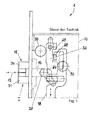
- Fig.1 shows a section of a lock for a door according to the prior art and is already described in the introductory part of the present description.
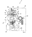
- Fig. 2 shows a lock 1 in a partial view with a housing 10 in which a cross-latch 11 is movably received in a thrust direction 12 and the thrust direction 12 corresponds to the X-direction shown, which represents the Domrichraum of the castle.
- the cross latch 11 is in a closed position I and protrudes from a forend 32 on the front side out of the housing 10.
- the lock 1 comprises a locking element 33, which is also shown protruding from the forend 32, in order to lock in a strike plate the door in which the lock 1 can be received.
- the lock 1 furthermore has a control catch 34, by means of which a self-locking of the locking element 33, for example, then effected in the manner of a closing sequence control can be when the control catch 34 comes into contact with the strike plate in the door frame.
- the cross latch 11 serves for mechanical pressure relief of the locking element 33, since the cross latch 11 has a greater width than the width of the locking element 33.
- a slider element 18 which is movable in the vertical direction, that of the Y-direction shown equivalent. The vertical movement of the slider element 18 can be triggered for example by a door handle, which is received in a follower 36, wherein the follower 36 acts via a lever 37 against a stop 38 on the slider element 18 to move it vertically.
- the slider element 18 is accommodated in the housing 10 of the lock 1 and cooperates with the locking element 33 via a link arrangement 35. If the slider element 18 moves vertically upward in the positive Y direction, then the locking element 33 can be retracted into the housing 10. The retraction of the locking element 33 can be done with a standard correspondingly low force, since the locking element 33 is not applied against the strike plate and thus forms no friction.
- the blocking device for blocking the cross latch 11 can be released, so that then the cross latch 11 can also move into the housing 10 in order to release the door through the lock 1 from the frame.
- the cross latch 11 is shown protruding out of the housing 10, and the blocking device blocks the cross latch 11 in the arrangement shown.
- the mode of action the blocking device according to the invention and its execution as a toggle lever arrangement 13 is described in more detail below.
- the blocking device is formed by a knee lever assembly 13, which forms an effective link between the slider element 18 and the cross latch 11.
- the toggle lever arrangement 13 has a first lever element 14 and a second lever element 15, wherein the lever elements 14 and 15 are connected to one another via an articulated connection 16.
- the first lever member 14 is rotatably received about a guide member 19 about this, wherein the guide member 19 is displaceable in the Y direction in the housing 10.
- the second lifting element 15 is rotatably received about a housing-fixed axis 22, wherein the lever elements 14 and 15 for securing the closed position II lie in their longitudinal extent approximately in a common vertically aligned axis.
- the first lever element 14 has a guide contour 24 against which a pressure roller 20 designed as a roller 20 abuts.
- the pressure body 20 is received on a latch neck 17 of the cross latch 11, so that a movement of the cross latch 11 is blocked in the negative X direction.
- the blocking of the cross latch 11 is due, in particular, to the fact that the receiving point of the first lever element 14, which is formed by the guide element 19, lies approximately behind the pressure element 20 in the X direction.
- the first lever member 14 In order to release the cross latch 11, therefore, the first lever member 14 must be moved with the guide member 19 from the position behind the pressure roller 20. Only so that the blocking device is released and the cross latch 11 can be transferred from the closed position I shown in an open position II, as this in the following Fig. 3 is shown.
- the support disk 41 is disposed between the trap neck 17 and the pressure body 20 and ensures that the first lever member 14 is not under load from the slot 25 on the crosshatch wings 31 when the door is closed (see FIG. 3 ) pops out.
- Fig. 3 shows a lock 1 with a cross latch 11 in an open position II with an activated toggle lever assembly 13, so that a blocking action of the cross latch 11 is released.
- the operation of the transfer of the closed position I in the open position II of the cross latch 11 is based on Fig. 3 in synopsis with Fig. 2 described below.
- Fig. 3 the toggle lever assembly 13 is shown in a state in which it has been transferred by activation from a blocking position to a release position.
- the slider 18 has been displaced vertically upward in the positive Y direction.
- the displacement of the slider 18 is effected for example by actuation of an unspecified door handle, which is received in a pusher 36.
- the slider element 18 can be displaced vertically by the lever 37 abuts against a stop 38 on the slider element 18.
- the effective contact between the abutment surface 28 on the slider element 18 against the driving arm 21 of the second lever element 15 is such that the locking element 33 is securely retracted into the housing 10 of the lock 1, that is, the cross latch 11 is always wider than the locking element 33.
- the cross latch 11 is already in the open position II by the activation effected and the further insertion of the cross latch 11 is carried out by a force of the striking plate against the funnel falleneriel 31, so that the cross latch 11 with the latch neck 17 in the forend 32 of the Lock 1 is pressed.
- the unlocking of the blocking device causes angling of the lever members 14 and 15 to each other, so that these from a mutually extended position ( Fig. 2 ) in an angled position ( Fig. 3 ) are transferred.
- the rotation of the second lever member 15 about the axis 22 is under tension of a return spring 23, and the door handle is released again and the slider member 18 is moved by a slider spring 39 back in the negative Y direction vertically down, so relaxes the return spring 23 again but only up to a certain position if the door is not closed again.
- the lock 1 comprises a latch spring 40, with which the cross latch 11 is biased in the thrust direction 12 in the positive X direction.
- the latch spring 40 is designed as a comparatively weak spring to make the indentation forces of the cross latch 11 in the housing 10 as low as possible.
Landscapes
- Lock And Its Accessories (AREA)
- Casings For Electric Apparatus (AREA)
Abstract
Description
- Die vorliegende Erfindung betrifft ein Schloss für eine Tür mit einem Gehäuse, in dem eine Kreuzfalle in einer Schubrichtung beweglich aufgenommen ist, sodass die Kreuzfalle in eine Schließstellung bringbar ist, in der diese aus dem Gehäuse hervorspringt und sodass die Kreuzfalle in eine Öffnungsstellung bringbar ist, in der diese in das Gehäuse zurückgezogen ist, und wobei eine Blockiereinrichtung vorgesehen ist, mit der die Kreuzfalle in der Schließstellung blockierbar ist.
-
Figur 1 zeigt eine schematische Darstellung eines Schlosses 1 zum Einbau in ein Türblatt mit einem Gehäuse 10, in dem eine Kreuzfalle 11 in einer Schubrichtung 12 beweglich aufgenommen ist. Kreuzfallen 11 dienen in der Regel zur Druckentlastung von Riegelelementen, indem die Kreuzfalle 11 eine Breite aufweist, die größer ist als die Breite des Riegelelementes. Damit wird erreicht, dass die Schließkraft der Tür über die Kreuzfalle 11 aufgenommen wird, indem das Schließblech an der Kreuzfalle 11 zur Anlage gelangt, während das Riegelelement gegenüber dem Schließblech frei beweglich und somit druckentlastet ist. So kann das Riegelelement durch Betätigung des Schlosses aus dem Schließblech kraftminimal zurückgezogen werden, und erst auf einem letzten Wegabschnitt beim Zurückziehen des Riegelelementes in das Gehäuse 10 des Schlosses 1 wird die Kreuzfalle 11 entsperrt, sodass diese selbsttätig in das Gehäuse 10 zurückgedrückt werden kann, beispielsweise indem die Tür manuell vom Schließblech wegbewegt wird. - Zum Blockieren der Kreuzfalle 11 in der gezeigten Schließstellung I dient ein Klemmelement 26, durch das die Kreuzfalle 11 in der gezeigten Schließstellung I gehalten wird. Hierzu weist das Klemmelement 26 eine Keilfläche 27 auf, gegen die ein Druckkörper 20 in Form einer Rolle 20 zur Anlage gelangt, wobei der Druckkörper 20 am Fallenhals 17 der Kreuzfalle 11 aufgenommen ist.
- Das Schloss 1 weist ferner ein Schieberelement 18 auf, das mit dem Klemmelement 26 zusammenwirkt, um dieses ebenso wie das Schieberelement 18 vertikal zu bewegen. Hierzu besitzt das Schieberelement 18 eine Anschlagfläche 28, und wird das Schieberelement 18 in der gezeigten Ansicht nach oben bewegt, kann die Anschlagfläche 28 gegen einen Anschlag 29 am Klemmelement 26 anschlagen, sodass das Klemmelement 26 ebenfalls nach oben bewegt wird. Infolge der Bewegung des Klemmelementes 26 nach oben wird der Druckkörper 20 am Fallenhals 17 von der Keilfläche 27 des Klemmelementes 26 gelöst, und die Kreuzfalle 11 kann in das Gehäuse 10 des Schlosses 1 eingeschoben werden.
- Das so gebildete Gehemme basiert folglich auf dem Prinzip eines Klemmkeils, der durch das Klemmelement 26 mit der Keilfläche 27 gebildet ist, wobei nachteilhafterweise das Klemmelement 26 beispielsweise durch Führungselemente 30 aufwändig im Gehäuse 10 geführt werden muss, damit dieses durch lediglich eine geringe Lösekraft aus der blockierenden Anordnung gegen den Druckkörper 20 gelöst werden kann. Der Keilwinkel der Keilfläche 27 muss mit weiterem Nachteil sehr genau ausgeführt werden, und eine maßliche Abweichung der Keilfläche 27 in Schubrichtung 12 bewirkt aufgrund des steilen Keilwinkels bereits eine große erforderliche Änderung der Lage des Klemmelementes 26 in vertikaler Richtung.
- Je weiter das Klemmelement nach unten verfährt, desto eher berührt somit das Schieberelement das Klemmelement während der Entriegelung des Schlosses, dadurch kann es vorkommen, dass die Kreuzfallenflügel 31 der Kreuzfalle 11 sich so weit ineinander drehen, dass das Riegelelement nicht mehr druckentlastet ist und gegen das Schließblech zur Anlage gelangt, da die Gesamtbreite der Kreuzfallenflügel geringer geworden ist als die Riegelbreite.
- Um ein Schloss beispielsweise als Panikschloss auszuführen, gibt es normativ limitierte Kräfte, die nicht überschritten werden dürfen, um das Riegelelement in das Schloss zurückzuziehen. Kommt aufgrund der Entriegelung der Kreuzfalle das Riegelelement gegen das Schließblech zur Anlage, so entsteht der Nachteil, das die normativ limitierten Kräfte aufgrund entstehender Reibung und einer möglichen Klemmung nicht eingehalten werden können.
- Es ist damit die Aufgabe der vorliegenden Erfindung, ein Schloss mit einer Kreuzfalle zu schaffen, die in verbesserter Weise durch eine Blockiereinrichtung in einer Schließstellung gehalten werden kann, insbesondere ergibt sich die Aufgabe, eine verbesserte Blockiereinrichtung zu schaffen, mit der die Kreuzfalle auf einfache Weise in der Schließstellung blockierbar ist.
- Diese Aufgabe wird ausgehend von einem Schloss für eine Tür gemäß dem Oberbegriff des Anspruchs 1 in Verbindung mit den kennzeichnenden Merkmalen gelöst. Vorteilhafte Weiterbildungen der Erfindung sind in den abhängigen Ansprüchen angegeben.
- Die Erfindung schließt die technische Lehre ein, dass die Blockiereinrichtung durch eine Kniehebelanordnung gebildet ist, die ein erstes Hebeelement und ein zweites Hebelelement umfasst, wobei die Hebelelemente über eine Gelenkverbindung miteinander verbunden sind.
- Durch die Ausführung der Blockiereinrichtung als Kniehebelanordnung wird der Vorteil erreicht, dass keine Keilfläche notwendig ist, um direkt oder über einen Druckkörper mit der Kreuzfalle zusammenzuwirken und um diese zu blockieren. Insbesondere weist die Kniehebelanordnung kein Bauteil auf, das aufwendig im Gehäuse des Schlosses geführt werden muss, wie dies zur Führung des Klemmelementes mit der Keilfläche notwendig ist, Durch die Kniehebelanordnung mit dem ersten und zweiten Hebelelement wird eine Kraftübersetzung erreicht, um mit einer geringen Lösekraft einen Blockierkörper in eine Blockierposition zu bewegen, sodass die Kreuzfalle in vollständig aus dem Gehäuse ausgefahrener Position gehalten wird.
- Gemäß einer vorteilhaften Variante der Kniehebelanordnung kann die Kreuzfalle über einen Fallenhals mit dem ersten Hebelelement zusammenwirken. Weiterhin kann ein Schieberelement vorgesehen und im Gehäuse beweglich aufgenommen sein, wobei das zweite Hebelelement um eine gehäusefeste Achse drehbar ist und zur Wirkverbindung mit dem Schieberelement ausgebildet ist. Durch die Wirkverbindung kann das zweite Hebelelement durch das Schieberelement aktiviert werden, um beispielsweise die Blockiereinrichtung von einer Blockierstellung in eine Freigabestellung zu überführen. Durch die Verbindung der Hebelelemente über die Gelenkverbindung kann bei Aktivierung des zweiten Hebelelementes durch das Schieberelement das erste Hebelelement ebenfalls bewegt werden, das über den Fallenhals mit der Kreuzfalle zusammenwirkt, und den Blockierkörper bildet. Die Kniehebelanordnung ist dabei so ausgeführt, dass eine Lösekraft, die vom Schieberelement auf das zweite Hebelelement notwendig ist, deutlich geringer ausfallen kann als eine Kraft, die notwendig ist, um das erste Hebelelement so in Wirkverbindung mit der Kreuzfalle zu bringen, dass diese in der Schließstellung blockiert.
- Um das erste Hebelelement zwischen der Blockierstellung und der Freigabestellung relativ zum Fallenhals der Kreuzfalle zu bewegen, ist gemäß einem weiteren Ausführungsbeispiel vorgesehen, das erste Hebelement in einem Führungselement drehbar aufzunehmen und über dieses am oder im Gehäuse beweglich zu führen. Die Kniehebelanordnung kann dabei in einer Blockierstellung im Wesentlichen gestreckt sein, sodass das erste Hebelelement in der Schließstellung die Kreuzfalle insbesondere über einen am Fallenhals aufgenommenen Druckkörper blockiert. Damit nimmt die Kniehebelanordnung in der gestreckten Stellung, in der sich beide Hebelelemente etwa in einer gemeinsamen Achse erstrecken, die Blockierstellung ein, und wird das zweite Hebelelement durch das Schieberelement aktiviert, so dreht dieses um eine gehäusefeste Achse, und die Längsachsen der Hebelemente schließen darauf folgend einen Winkel zueinander ein, wodurch die Freigabestellung der Blocklereinrichtung wiedergegeben ist. Während die Hebelelemente in eine Position überführt werden, in der diese einen Winkel zueinander einschließen, bewegt sich das Führungselement relativ zum Gehäuse, und das Hebelelement kann die Kreuzfalle über den Fallenhals freigeben.
- Mit weiterem Vorteil kann das zweite Hebelelement einen Mitnehmerarm aufweisen, der zur Wechselwirkung mit dem Schieberelement ausgebildet ist, wobei die Kniehebelanordnung bei Wechselwirkung des Schieberelementes mit dem Mitnehmerarm aus der gestreckten und die Kreuzfalle blockierenden Anordnung herausführbar ist, indem das zweite Hebelelement um die gehäusefeste Achse dreht. Wird die Kniehebelanordnung aus der Schließstellung herausgeführt, und schließen die Hebelelemente einen Winkel zueinander ein, so bewegt sich das Führungselement, an dem das erste Hebelelement drehbar aufgenommen ist, in gleicher Richtung wie das Schieberelement, wobei die Bewegungsrichtung quer zur Schubrichtung der Kreuzfalle verläuft. Folglich wird die Linearbewegung des Schieberelementes über den Mitnehmerarm des zweiten Hebelelementes in eine Drehbewegung des zweiten Hebelelementes überführt, und die Drehbewegung des zweiten Hebelelementes wird über die Gelenkverbindung in eine Schwenk-Hubbewegung des ersten Hebelelementes überführt. Durch den Hubanteil der Bewegung im ersten Hebelelement wird dieses aus der Blockierstellung gegen den Druckkörper am Fallenhals der Kreuzfalle gelöst, sodass im weiteren Verlauf die Kreuzfalle mit äußerst geringer Kraft in das Gehäuse des Schlosses eingeschoben werden kann, während sich der Winkel zwischen den beiden Hebelelementen kontinuierlich weiter verkleinert.
- Um die Kniehebelanordnung wenigstens leicht in ihre Blockierstellung vorzuspannen, kann eine Rückholfeder vorgesehen sein und beispielsweise mit dem zweiten Hebelelement zusammenwirken. Die Rückholfeder kann beispielsweise als Schenkelfeder ausgeführt sein und mit einem ersten Schenkel gehäusefest abgestützt sein, sodass der zweite Schenkel vorzugsweise gegen den Mitnehmerarm des zweiten Hebelelementes drückt. Gelangt der Schieber wieder außer Eingriff mit dem zweiten Hebelelement, und ist die Tür geöffnet, das heißt das Schließblech ist außer Eingriff mit der Kreuzfalle, so führt eine Kreuzfallenfeder die Kreuzfalle wieder in die Schließstellung zurück, und zugleich führt die Rückholfeder die Kniehebelanordnung wieder in Richtung Blockierstellung zurück.
- Weiterhin ist es von Vorteil, das erste Hebelelement mit einer Führungskontur auszuführen, mit der die Kreuzfalle, insbesondere aber der Fallenhals und bevorzugt der Druckkörper, zusammenwirken. Die Führungskontur kann sich teilweise randseitig um das Führungselement herum erstrecken, da dieses vom ersten Hebelelement umschlossen ist und da das erste Hebelelement um das Führungselement verdrehen kann. Die Führungskontur dient dabei zum Druckkontakt gegen den Druckkörper, der am Fallenhals der Kreuzfalle aufgenommen ist. Insbesondere kann der Druckkörper eine Rolle bilden, die zum Abrollen an der Führungskontur des ersten Hebelelementes ausgebildet ist. Insbesondere dann, wenn die Kniehebelanordnung aktiviert wurde, und diese die gestreckte Anordnung der Hebelelemente verlassen hat, kann durch Eindrücken der Kreuzfalle die Rolle an der Führungskontur weiter entlang rollen, wodurch die Lage des Führungselementes, an dem das erste Hebelelement drehbar aufgenommen ist, selbsttätig weiter verändert wird, ohne dass der Schieber weiter gegen den Mitnehmerarm des zweiten Hebelelementes wirken muss. Damit wird erreicht, dass das Schieberelement lediglich zum Auslösen der Kniehebelanordnung gegen den Mitnehmerarm am zweiten Hebelelement gelangen muss, um im weiteren Verlauf eine Bewegung der Kreuzfalle in die Öffnungsstellung zu gewährleisten, wodurch zugleich ein weiteres Einwinkeln der Hebelelemente zueinander erreicht wird.
- Zur Führung des Führungselementes kann wenigstens ein Langloch beispielsweise im Gehäuse des Schlosses vorgesehen sein, sodass über die Kreuzfalle auf das erste Hebelelement wirkende Kräfte mit dem Führungselement in das Gehäuse ableitbar sind. Das Langloch erstreckt sich dabei etwa senkrecht zur Schubrichtung der Kreuzfalle, wobei die Schubrichtung der Dornmaßrichtung des Schlosses entspricht.
- Die Erfindung verbessernde Maßnahmen werden nachstehend gemeinsam mit der Beschreibung eines bevorzugten Ausführungsbeispiels der Erfindung anhand der Figuren näher dargestellt, Es zeigt:
- Figur 1
- einen Ausschnitt eines Schlosses für eine Tür mit einer Blockiereinrichtung gemäß dem Stand der Technik,
- Figur 2
- ein Schloss für eine Tür mit einer Blockiereinrichtung, die erfindungsgemäß durch eine Kniehebelanordnung gebildet ist und die in einer Blockierstellung gezeigt ist und
- Figur 3
- das Schloss für eine Tür mit der Kniehebelanordnung, die in einer Freigabestellung gezeigt ist.
-
Fig.1 zeigt einen Ausschnitt aus einem Schloss für eine Tür gemäß dem Stand der Technik und ist im einleitenden Teil der vorliegenden Beschreibung bereits beschrieben. -
Fig. 2 zeigt ein Schloss 1 in einer Teildarstellung mit einem Gehäuse 10, in dem eine Kreuzfalle 11 in einer Schubrichtung 12 beweglich aufgenommen ist und die Schubrichtung 12 entspricht der gezeigten X-Richtung, die die Dommaßrichtung des Schlosses wiedergibt. Die Kreuzfalle 11 befindet sich in einer Schließstellung I und ragt aus einem Stulp 32 vorderseitig aus dem Gehäuse 10 heraus. Weiterhin umfasst das Schloss 1 ein Riegelelement 33, das ebenfalls aus dem Stulp 32 hervorspringend gezeigt ist, um in einem Schließblech die Tür, in der das Schloss 1 aufgenommen werden kann, zu verriegeln. Das Schloss 1 weist weiterhin eine Steuerfalle 34 auf, durch die nach Art einer Schließfolgeregelung eine Selbstverriegelung des Riegelelementes 33 beispielsweise dann bewirkt werden kann, wenn die Steuerfalle 34 mit dem Schließblech in der Türzarge in Kontakt gelangt. - Verschließt das Schloss 1 die Tür in der Türzarge, so dient zum Verschließen das Riegelelement 33, das in einer Schließposition aus dem Gehäuse 10 des Schlosses 1 hervorspringt, um in ein dem Stulp 32 gegenüberliegendes Schließblech einzugreifen. Die Kreuzfalle 11 dient dabei zur mechanischen Druckentlastung des Riegelelementes 33, da die Kreuzfalle 11 eine größere Breite aufweist als die Breite des Riegelelementes 33. Zur Aktivierung des Riegelelementes 33 dient ein Schieberelement 18, das in vertikaler Richtung beweglich ist, die der gezeigten Y-Richtung entspricht. Die vertikale Bewegung des Schieberelementes 18 kann beispielsweise durch einen Türdrücker ausgelöst werden, der in einer Drückernuss 36 aufgenommen ist, wobei die Drückernuss 36 über einen Hebel 37 gegen einen Anschlag 38 am Schieberelement 18 wirkt, um dieses vertikal zu verlagern. Das Schieberelement 18 ist im Gehäuse 10 des Schlosses 1 aufgenommen und wirkt über eine Kulissenanordnung 35 mit dem Riegelelement 33 zusammen. Bewegt sich das Schieberelement 18 in positiver Y-Richtung vertikal nach oben, so kann das Riegelelement 33 in das Gehäuse 10 eingezogen werden. Das Einziehen des Riegelelementes 33 kann mit einer der Norm entsprechend geringen Kraft erfolgen, da das Riegelelement 33 nicht gegen das Schließblech anliegt und sich somit keine Reibung bildet. Bei einer Weiterbewegung des Schieberelementes 18 kann die Blockiereinrichtung zur Blockierung der Kreuzfalle 11 gelöst werden, so dass sich anschließend die Kreuzfalle 11 ebenfalls in das Gehäuse 10 hinein bewegen kann, um die Tür durch das Schloss 1 aus der Zarge freizugeben. In der Darstellung ist die Kreuzfalle 11 aus dem Gehäuse 10 hervorspringend gezeigt, und die Blockiereinrichtung blockiert die Kreuzfalle 11 in der gezeigten Anordnung. Die Wirkungsweise der erfindungsgemäßen Blockiereinrichtung und deren Ausführung als Kniehebelanordnung 13 ist im Folgenden näher beschrieben.
- Die Blockiereinrichtung ist durch eine Kniehebelanordnung 13 gebildet, die ein Wirkungsglied zwischen dem Schieberelement 18 und der Kreuzfalle 11 bildet. Die Kniehebelanordnung 13 weist hierfür ein erstes Hebelelement 14 und eine zweites Hebelelement 15 auf, wobei die Hebelelemente 14 und 15 über eine Gelenkverbindung 16 miteinander verbunden sind. Das erste Hebelelement 14 ist über ein Führungselement 19 um dieses drehbar aufgenommen, wobei das Führungselement 19 in Y-Richtung im Gehäuse 10 verlagerbar ist. Das zweite Hebelement 15 ist um eine gehäusefeste Achse 22 drehbar aufgenommen, wobei die Hebelelemente 14 und 15 zur Sicherung der Schließstellung II in ihren Längserstreckungen etwa in einer gemeinsamen vertikal ausgerichteten Achse liegen.
- Das erste Hebelelement 14 weist eine Führungskontur 24 auf, gegen die ein als Rolle 20 ausgeführter Druckkörper 20 anstößt. Der Druckkörper 20 ist an einem Fallenhals 17 der Kreuzfalle 11 aufgenommen, so dass eine Bewegung der Kreuzfalle 11 in negativer X-Richtung blockiert ist. Die Blockierung der Kreuzfalle 11 liegt insbesondere darin begründet, dass der Aufnahmepunkt des ersten Hebelelementes 14, der durch das Führungselement 19 gebildet ist, in X-Richtung etwa hinter dem Druckkörper 20 liegt. Um die Kreuzfalle 11 freizugeben, muss folglich das erste Hebelelement 14 mit dem Führungselement 19 aus der Position hinter der Druckrolle 20 bewegt werden. Erst damit wird die Blockiereinrichtung gelöst und die Kreuzfalle 11 kann aus der gezeigten Schließstellung I in eine Öffnungsstellung II überführt werden, wie diese in der folgenden
Fig. 3 dargestellt ist. - Die Stützscheibe 41 ist zwischen Fallenhals 17 und Druckkörper 20 angeordnet und sorgt dafür, dass das erste Hebelelement 14 bei Belastung auf die Kreuzfallenflügel 31 bei geschlossener Tür nicht aus seinem Langloch 25 (siehe
Figur 3 ) herausspringt. -
Fig. 3 zeigt ein Schloss 1 mit einer Kreuzfalle 11 in einer Öffnungsstellung II mit einer aktivierten Kniehebelanordnung 13, sodass eine Blockierwirkung der Kreuzfalle 11 aufgehoben ist. Die Wirkungsweise der Überführung der Schließstellung I in die Öffnungsstellung II der Kreuzfalle 11 wird anhand vonFig. 3 in Zusammenschau mitFig. 2 nachfolgend beschrieben. - In
Fig. 3 ist die Kniehebelanordnung 13 in einem Zustand gezeigt, in dem diese durch eine Aktivierung aus einer Blockierstellung in eine Freigabestellung überführt worden ist. Um die Kniehebelanordnung 13 zu aktivieren, ist der Schieber 18 in positiver Y-Richtung vertikal nach oben verlagert worden. Die Verlagerung des Schiebers 18 ist beispielsweise durch Betätigung eines nicht näher bezeichneten Türdrückers erfolgt, der in einer Drückernuss 36 aufgenommen ist. Über einen Hebel 37, der mit der Drückernuss 36 verbunden ist, kann das Schieberelement 18 vertikal verlagert werden, indem der Hebel 37 gegen einen Anschlag 38 am Schieberelement 18 anstößt. - Verlagert sich das Schieberelement 18 in positiver Y-Richtung vertikal nach oben, so gelangt eine Anschlagfläche 28 am Schieberelement 18 gegen einen Mitnehmerarm 21, der am zweiten Hebelelement 15 angeordnet ist. Dadurch wird das zweite Hebelelement 15 der Kniehebelanordnung 13 um die gehäusefeste Achse 22 verdreht, und durch die Gelenkverbindung 16 verdreht sich das erste Hebelelement 14 im Führungselement 19. Zugleich wandert das Führungselement 19 in einem Langloch 25, das beispielsweise im Gehäuseblech eingebracht ist, in positiver Y-Richtung vertikal nach oben, wodurch das erste Hebelelement 14 aus der Anordnung hinter dem Druckkörper bewegt wird.
- Der Wirkkontakt zwischen der Anschlagfläche 28 am Schieberelement 18 gegen den Mitnehmerarm 21 des zweiten Hebelelementes 15 erfolgt so, dass das Riegelelement 33 gesichert in das Gehäuse 10 des Schlosses 1 eingezogen wird, d.h., dass die Kreuzfalle 11 immer breiter als das Riegelelement 33 ist. In der gezeigten Stellung befindet sich die Kreuzfalle 11 durch die erfolgte Aktivierung bereits in der Öffnungsstellung II und der weitere Einschub der Kreuzfalle 11 erfolgt durch eine Krafteinwirkung des Schließbleches gegen die Kreuzfallenflügel 31, so dass die Kreuzfalle 11 mit dem Fallenhals 17 in den Stulp 32 des Schlosses 1 gedrückt wird.
- Die Entriegelungsposition der Blockiereinrichtung bewirkt ein Anwinkeln der Hebelelemente 14 und 15 zueinander, so dass diese aus einer zueinander gestreckten Position (
Fig. 2 ) in eine angewinkelte Position (Fig. 3 ) überführt werden. Die Verdrehung des zweiten Hebelelementes 15 um die Achse 22 erfolgt unter Spannung einer Rückholfeder 23, und wird der Türdrücker wieder losgelassen und wird das Schieberelement 18 über eine Schieberfeder 39 wieder in negativer Y-Richtung vertikal nach unten bewegt, so entspannt sich die Rückholfeder 23 wieder, jedoch nur bis zu einer bestimmten Position, wenn die Tür noch nicht wieder verschlossen ist. - Weiterhin umfasst das Schloss 1 eine Fallenfeder 40, mit der die Kreuzfalle 11 in Schubrichtung 12 in positiver X-Richtung vorgespannt ist. Die Fallenfeder 40 ist dabei als vergleichsweise schwache Feder ausgeführt, um die Eindrückkräfte der Kreuzfalle 11 in das Gehäuse 10 möglichst gering zu gestalten.
- Die Erfindung beschränkt sich in ihrer Ausführung nicht auf das vorstehend angegebene und lediglich bevorzugte Ausführungsbeispiel. Vielmehr ist eine Anzahl von Varianten denkbar, welche von der dargestellten Lösung auch bei grundsätzlich anders gearteten Ausführungen Gebrauch macht. Sämtliche aus den Ansprüchen, der Beschreibung oder den Zeichnungen hervorgehenden Merkmale und/oder Vorteile einschließlich konstruktiver Einzelheiten oder räumlicher Anordnungen, können sowohl für sich als auch in den verschiedensten Kombinationen erfindungswesentlich sein.
-
- 1
- Schloss
- 10
- Gehäuse
- 11
- Kreuzfalle
- 12
- Schubrichtung
- 13
- Kniehebelanordnung
- 14
- erstes Hebelelement
- 15
- zweites Hebelelement
- 16
- Gelenkverbindung
- 17
- Fallenhals
- 18
- Schieberelement
- 19
- Führungselement
- 20
- Druckkörper, Rolle
- 21
- Mitnehmerarm
- 22
- Achse
- 23
- Rückholfeder
- 24
- Führungskontur
- 25
- Langloch
- 26
- Klemmelement
- 27
- Keilfläche
- 28
- Anschlagfläche
- 29
- Anschlag
- 30
- Führungselement
- 31
- Kreuzfallenflügel
- 32
- Stulp
- 33
- Riegelelement
- 34
- Steuerfalle
- 35
- Kulissenanordnung
- 36
- Drückernuss
- 37
- Hebel
- 38
- Anschlag
- 39
- Schieberfeder
- 40
- Fallenfeder
- 41
- Stützscheibe
- X- Richtung
- Schubrichtung, Dornmaßrichtung
- Y- Richtung
- Vertikalrichtung
- I
- Schließstellung
- II
- Öffnungsstellung
Claims (10)
- Schloss (1) für eine Tür mit einem Gehäuse (10), in dem eine Kreuzfalle (11) in einer Schubrichtung (12) beweglich aufgenommen ist, sodass die Kreuzfalle (11) in eine Schließstellung (I) bringbar ist, in der diese aus dem Gehäuse (10) hervorspringt und sodass die Kreuzfalle (11) in einer Öffnungsstellung (II) bringbar ist, in der diese in das Gehäuse (10) zurückgezogen ist, und wobei eine Blockiereinrichtung vorgesehen ist, mit der die Kreuzfalle (11) in der Schließstellung (I) blockierbar ist, dadurch gekennzeichnet, dass die Blockiereinrichtung durch eine Kniehebelanordnung (13) gebildet ist, die ein erstes Hebelelement (14) und ein zweites Hebelelement (15) umfasst, wobei die Hebelelemente (14, 15) über eine Gelenkverbindung (16) miteinander verbunden sind.
- Schloss (1) nach Anspruch 1, dadurch gekennzeichnet, dass die Kreuzfalle (11) über einen Fallenhals (17) mit dem ersten Hebelelement (14) zusammenwirkt.
- Schloss (1) nach Anspruch 1 oder 2, dadurch gekennzeichnet, dass ein Schieberelement (18) vorgesehen und im Gehäuse (10) beweglich aufgenommen ist, wobei das zweite Hebelelement (15) um eine gehäusefeste Achse (22) drehbar ist und zur Wirkverbindung mit dem Schieberelement (18) ausgebildet ist.
- Schloss (1) nach einem der Ansprüche 1 bis 3, dadurch gekennzeichnet, dass das erste Hebelelement (14) in einem Führungselement (19) drehbar aufgenommen und über dieses am oder im Gehäuse (10) beweglich geführt ist.
- Schloss (1) nach einem der vorgenannten Ansprüche, dadurch gekennzeichnet, dass die Kniehebelanordnung (13) in einer Blockierstellung im Wesentlichen gestreckt ist, sodass das erste Hebelelement (14) in der Schließstellung (I) die Kreuzfalle (11) insbesondere über einen am Fallenhals (17) aufgenommenen Druckkörper (20) blockiert,
- Schloss (1) nach Anspruch 3 bis 5, dadurch gekennzeichnet, dass das zweite Hebelelement (15) einen Mitnehmerarm (21) aufweist, der zur Wechselwirkung mit dem Schieberelement (18) ausgebildet ist, wobei die Kniehebelanordnung (13) bei Wechselwirkung des Schieberelementes (18) mit dem Mitnehmerarm (21) aus der gestreckten und die Kreuzfalle (11) blockierenden Anordnung herausführbar ist, indem das zweite Hebelelement (15) um die gehäusefeste Achse (22) dreht.
- Schloss (1) nach einem der vorgenannten Ansprüche, dadurch gekennzeichnet, dass eine Rückholfeder (23) vorgesehen ist und mit dem zweiten Hebelelement (15) derart zusammenwirkt, dass diese die Kniehebelanordnung (13) in ihre Blockierstellung vorspannt.
- Schloss (1) nach einem der vorgenannten Ansprüche, dadurch gekennzeichnet, dass das erste Hebelelement (14) eine Führungskontur (24) aufweist, mit der die Kreuzfalle (11), insbesondere der Fallenhals (17), bevorzugt über den Druckkörper (20), zusammenwirkt.
- Schloss (1) nach Anspruch 8, dadurch gekennzeichnet, dass der Druckkörper (20) als Rolle (20) ausgebildet ist, die zum Abrollen an der Führungskontur (24) des ersten Hebelelementes (14) ausgebildet ist.
- Schloss (1) nach Anspruch 4 bis 9, dadurch gekennzeichnet, dass das Führungselement (19) in wenigstens einem Langloch (25) im Gehäuse (10) geführt ist, sodass über die Kreuzfalle (11) auf das erste Hebelelement (14) wirkende Kräfte mit dem Führungselement (19) in das Gehäuse (10) ableitbar sind.
Applications Claiming Priority (1)
| Application Number | Priority Date | Filing Date | Title |
|---|---|---|---|
| DE102012108242.1A DE102012108242A1 (de) | 2012-09-05 | 2012-09-05 | Schloss für eine Tür |
Publications (3)
| Publication Number | Publication Date |
|---|---|
| EP2706174A2 true EP2706174A2 (de) | 2014-03-12 |
| EP2706174A3 EP2706174A3 (de) | 2017-04-19 |
| EP2706174B1 EP2706174B1 (de) | 2019-04-03 |
Family
ID=49123623
Family Applications (1)
| Application Number | Title | Priority Date | Filing Date |
|---|---|---|---|
| EP13004218.7A Active EP2706174B1 (de) | 2012-09-05 | 2013-08-27 | Schloss für eine tür |
Country Status (4)
| Country | Link |
|---|---|
| EP (1) | EP2706174B1 (de) |
| CN (1) | CN103670049A (de) |
| DE (1) | DE102012108242A1 (de) |
| ES (1) | ES2727048T3 (de) |
Cited By (5)
| Publication number | Priority date | Publication date | Assignee | Title |
|---|---|---|---|---|
| CN107165505A (zh) * | 2017-07-21 | 2017-09-15 | 彭世明 | 自动弹出锁舌的控制装置及自动锁和应用 |
| EP3243985A1 (de) * | 2016-05-09 | 2017-11-15 | GEZE GmbH | Schloss für einen schwenkbaren flügel |
| CN109230533A (zh) * | 2018-09-03 | 2019-01-18 | 郑州福耀玻璃有限公司 | 一种汽车玻璃不间断烘弯线 |
| EP3438382A1 (de) | 2017-08-01 | 2019-02-06 | dormakaba Deutschland GmbH | Fallenanordnung eines schlosses |
| US11214982B2 (en) | 2015-09-18 | 2022-01-04 | Abloy Oy | Lock body |
Family Cites Families (10)
| Publication number | Priority date | Publication date | Assignee | Title |
|---|---|---|---|---|
| US349195A (en) * | 1886-09-14 | Combined latch and lock | ||
| DE3640418A1 (de) * | 1986-11-26 | 1988-06-09 | Electronic Alarm Kromer Gmbh | Blockschloss fuer einbruchmeldeanlagen (ema) |
| CN2071683U (zh) * | 1990-05-22 | 1991-02-20 | 荣成市机械设备厂 | 可上中下三点锁定的弹子门锁 |
| DE29605517U1 (de) * | 1996-03-26 | 1997-07-24 | Gretsch-Unitas GmbH Baubeschläge, 71254 Ditzingen | Verriegelungseinrichtung |
| DE29701070U1 (de) * | 1997-01-22 | 1998-05-20 | Ferco International Ferrures et Serrures de Bâtiment S.A., Reding | Schloß mit Falle für Tür oder Fenster |
| DE29719611U1 (de) * | 1997-11-05 | 1999-03-11 | Gretsch-Unitas GmbH Baubeschläge, 71254 Ditzingen | Schloß, insbesondere Einsteckschloß für eine Außentür |
| FR2896007B1 (fr) * | 2006-01-09 | 2011-06-10 | Sersys | Dispositif de verrouillage de porte |
| FR2911898B1 (fr) * | 2007-01-25 | 2019-06-07 | Saint Gobain Seva | Dispositif d'actionnement de pene et porte equipee dudit dispositif. |
| CN202081741U (zh) * | 2011-04-27 | 2011-12-21 | 瑞安市佩斯顿锁业有限公司 | 快速逃生防盗执手门锁 |
| DE102012104448A1 (de) * | 2012-05-23 | 2013-11-28 | Dorma Gmbh + Co. Kg | Schloss für eine Tür |
-
2012
- 2012-09-05 DE DE102012108242.1A patent/DE102012108242A1/de active Pending
-
2013
- 2013-08-27 ES ES13004218T patent/ES2727048T3/es active Active
- 2013-08-27 EP EP13004218.7A patent/EP2706174B1/de active Active
- 2013-09-05 CN CN201310472527.XA patent/CN103670049A/zh active Pending
Non-Patent Citations (1)
| Title |
|---|
| None |
Cited By (9)
| Publication number | Priority date | Publication date | Assignee | Title |
|---|---|---|---|---|
| US11214982B2 (en) | 2015-09-18 | 2022-01-04 | Abloy Oy | Lock body |
| EP3243985A1 (de) * | 2016-05-09 | 2017-11-15 | GEZE GmbH | Schloss für einen schwenkbaren flügel |
| CN107355134A (zh) * | 2016-05-09 | 2017-11-17 | 盖慈有限公司 | 用于可枢转的扇的锁 |
| CN107355134B (zh) * | 2016-05-09 | 2019-07-16 | 盖慈有限公司 | 用于可枢转的扇的锁 |
| CN107165505A (zh) * | 2017-07-21 | 2017-09-15 | 彭世明 | 自动弹出锁舌的控制装置及自动锁和应用 |
| CN107165505B (zh) * | 2017-07-21 | 2022-05-17 | 彭世明 | 自动弹出锁舌的控制装置及自动锁和应用 |
| EP3438382A1 (de) | 2017-08-01 | 2019-02-06 | dormakaba Deutschland GmbH | Fallenanordnung eines schlosses |
| CN109230533A (zh) * | 2018-09-03 | 2019-01-18 | 郑州福耀玻璃有限公司 | 一种汽车玻璃不间断烘弯线 |
| CN109230533B (zh) * | 2018-09-03 | 2024-03-19 | 郑州福耀玻璃有限公司 | 一种汽车玻璃不间断烘弯线 |
Also Published As
| Publication number | Publication date |
|---|---|
| EP2706174A3 (de) | 2017-04-19 |
| EP2706174B1 (de) | 2019-04-03 |
| ES2727048T3 (es) | 2019-10-11 |
| CN103670049A (zh) | 2014-03-26 |
| DE102012108242A1 (de) | 2014-03-06 |
Similar Documents
| Publication | Publication Date | Title |
|---|---|---|
| EP1932989B1 (de) | Schliessanlage für Türen, Fenster oder dergleichen, insbesondere Treibstangenschloss mit Panikfunktion und Mehrpunktverriegelung | |
| EP3109384B1 (de) | Schliessvorrichtung mit starker riegeldruckfeder | |
| DE4324300C2 (de) | Antipanik-Türschloß | |
| EP2673435B1 (de) | Schlosssystem für eine zweiflügelige türanlage mit panikfunktion | |
| EP2706174B1 (de) | Schloss für eine tür | |
| AT393710B (de) | Mehrriegelverschluss | |
| DE102011050226A1 (de) | Dispositif de commande de verrouillage pour vantail | |
| EP3569800B1 (de) | Schloss, insbesondere sperrfallenschloss | |
| EP3438382B1 (de) | Fallenanordnung eines schlosses | |
| EP2339096B1 (de) | Treibstangenschloss mit Panikfunktion und Mehrfachverriegelung | |
| EP3299546A1 (de) | Trennscheibe für paniknuss | |
| EP3805493A2 (de) | Modular aufgebautes schloss mit panikfunktion | |
| EP1953313B1 (de) | Schloss für eine Tür | |
| EP3907357A1 (de) | Verriegelungsvorrichtung | |
| DE102018128041A1 (de) | Schließvorrichtung an Fahrzeugen und Fahrzeughauben oder Fahrzeugklappen | |
| EP3628801B1 (de) | Schlossvorrichtung für eine tür und verfahren zum öffnen einer tür | |
| EP3543437B1 (de) | Schlossanordnung mit einem schloss für eine gangflügeltür und einem gegenschloss für eine standflügeltür | |
| EP3112564A1 (de) | Selbstverriegelndes fallenschloss | |
| EP1672153B1 (de) | Schloss mit Riegel und Riegelantrieb | |
| DE102018115985A1 (de) | Schlossgegenkasten für ein Aktivflügelschloss mit Falzluftausgleich | |
| EP2085543B1 (de) | Schloss | |
| DE102021118229A1 (de) | Schloss mit in einer zurückgezogenen Stellung fixierbaren Falle | |
| EP2148028B1 (de) | Riegeleinrichtung für Türen | |
| DE897216C (de) | Tuerschloss, insbesondere fuer Kraftwagen | |
| EP2927400B1 (de) | Schloss |
Legal Events
| Date | Code | Title | Description |
|---|---|---|---|
| PUAI | Public reference made under article 153(3) epc to a published international application that has entered the european phase |
Free format text: ORIGINAL CODE: 0009012 |
|
| AK | Designated contracting states |
Kind code of ref document: A2 Designated state(s): AL AT BE BG CH CY CZ DE DK EE ES FI FR GB GR HR HU IE IS IT LI LT LU LV MC MK MT NL NO PL PT RO RS SE SI SK SM TR |
|
| AX | Request for extension of the european patent |
Extension state: BA ME |
|
| RAP1 | Party data changed (applicant data changed or rights of an application transferred) |
Owner name: DORMA DEUTSCHLAND GMBH |
|
| PUAL | Search report despatched |
Free format text: ORIGINAL CODE: 0009013 |
|
| AK | Designated contracting states |
Kind code of ref document: A3 Designated state(s): AL AT BE BG CH CY CZ DE DK EE ES FI FR GB GR HR HU IE IS IT LI LT LU LV MC MK MT NL NO PL PT RO RS SE SI SK SM TR |
|
| AX | Request for extension of the european patent |
Extension state: BA ME |
|
| RIC1 | Information provided on ipc code assigned before grant |
Ipc: E05B 59/00 20060101ALI20170315BHEP Ipc: E05B 15/10 20060101ALI20170315BHEP Ipc: E05B 55/00 20060101AFI20170315BHEP Ipc: E05B 15/00 20060101ALI20170315BHEP Ipc: E05B 63/20 20060101ALN20170315BHEP |
|
| RAP1 | Party data changed (applicant data changed or rights of an application transferred) |
Owner name: DORMAKABA DEUTSCHLAND GMBH |
|
| STAA | Information on the status of an ep patent application or granted ep patent |
Free format text: STATUS: REQUEST FOR EXAMINATION WAS MADE |
|
| 17P | Request for examination filed |
Effective date: 20171017 |
|
| RBV | Designated contracting states (corrected) |
Designated state(s): AL AT BE BG CH CY CZ DE DK EE ES FI FR GB GR HR HU IE IS IT LI LT LU LV MC MK MT NL NO PL PT RO RS SE SI SK SM TR |
|
| STAA | Information on the status of an ep patent application or granted ep patent |
Free format text: STATUS: EXAMINATION IS IN PROGRESS |
|
| 17Q | First examination report despatched |
Effective date: 20180130 |
|
| RIC1 | Information provided on ipc code assigned before grant |
Ipc: E05B 59/00 20060101ALI20180830BHEP Ipc: E05B 15/00 20060101ALI20180830BHEP Ipc: E05B 55/00 20060101AFI20180830BHEP Ipc: E05B 15/10 20060101ALI20180830BHEP Ipc: E05B 63/20 20060101ALN20180830BHEP |
|
| GRAP | Despatch of communication of intention to grant a patent |
Free format text: ORIGINAL CODE: EPIDOSNIGR1 |
|
| STAA | Information on the status of an ep patent application or granted ep patent |
Free format text: STATUS: GRANT OF PATENT IS INTENDED |
|
| INTG | Intention to grant announced |
Effective date: 20181018 |
|
| GRAS | Grant fee paid |
Free format text: ORIGINAL CODE: EPIDOSNIGR3 |
|
| GRAA | (expected) grant |
Free format text: ORIGINAL CODE: 0009210 |
|
| STAA | Information on the status of an ep patent application or granted ep patent |
Free format text: STATUS: THE PATENT HAS BEEN GRANTED |
|
| AK | Designated contracting states |
Kind code of ref document: B1 Designated state(s): AL AT BE BG CH CY CZ DE DK EE ES FI FR GB GR HR HU IE IS IT LI LT LU LV MC MK MT NL NO PL PT RO RS SE SI SK SM TR |
|
| REG | Reference to a national code |
Ref country code: GB Ref legal event code: FG4D Free format text: NOT ENGLISH |
|
| REG | Reference to a national code |
Ref country code: CH Ref legal event code: EP Ref country code: AT Ref legal event code: REF Ref document number: 1115928 Country of ref document: AT Kind code of ref document: T Effective date: 20190415 |
|
| REG | Reference to a national code |
Ref country code: DE Ref legal event code: R096 Ref document number: 502013012520 Country of ref document: DE |
|
| REG | Reference to a national code |
Ref country code: IE Ref legal event code: FG4D Free format text: LANGUAGE OF EP DOCUMENT: GERMAN |
|
| REG | Reference to a national code |
Ref country code: SE Ref legal event code: TRGR |
|
| REG | Reference to a national code |
Ref country code: NL Ref legal event code: MP Effective date: 20190403 |
|
| REG | Reference to a national code |
Ref country code: LT Ref legal event code: MG4D |
|
| PG25 | Lapsed in a contracting state [announced via postgrant information from national office to epo] |
Ref country code: NL Free format text: LAPSE BECAUSE OF FAILURE TO SUBMIT A TRANSLATION OF THE DESCRIPTION OR TO PAY THE FEE WITHIN THE PRESCRIBED TIME-LIMIT Effective date: 20190403 |
|
| REG | Reference to a national code |
Ref country code: ES Ref legal event code: FG2A Ref document number: 2727048 Country of ref document: ES Kind code of ref document: T3 Effective date: 20191011 |
|
| PG25 | Lapsed in a contracting state [announced via postgrant information from national office to epo] |
Ref country code: CZ Free format text: LAPSE BECAUSE OF FAILURE TO SUBMIT A TRANSLATION OF THE DESCRIPTION OR TO PAY THE FEE WITHIN THE PRESCRIBED TIME-LIMIT Effective date: 20190403 Ref country code: LT Free format text: LAPSE BECAUSE OF FAILURE TO SUBMIT A TRANSLATION OF THE DESCRIPTION OR TO PAY THE FEE WITHIN THE PRESCRIBED TIME-LIMIT Effective date: 20190403 Ref country code: HR Free format text: LAPSE BECAUSE OF FAILURE TO SUBMIT A TRANSLATION OF THE DESCRIPTION OR TO PAY THE FEE WITHIN THE PRESCRIBED TIME-LIMIT Effective date: 20190403 Ref country code: NO Free format text: LAPSE BECAUSE OF FAILURE TO SUBMIT A TRANSLATION OF THE DESCRIPTION OR TO PAY THE FEE WITHIN THE PRESCRIBED TIME-LIMIT Effective date: 20190703 Ref country code: PT Free format text: LAPSE BECAUSE OF FAILURE TO SUBMIT A TRANSLATION OF THE DESCRIPTION OR TO PAY THE FEE WITHIN THE PRESCRIBED TIME-LIMIT Effective date: 20190803 Ref country code: AL Free format text: LAPSE BECAUSE OF FAILURE TO SUBMIT A TRANSLATION OF THE DESCRIPTION OR TO PAY THE FEE WITHIN THE PRESCRIBED TIME-LIMIT Effective date: 20190403 Ref country code: FI Free format text: LAPSE BECAUSE OF FAILURE TO SUBMIT A TRANSLATION OF THE DESCRIPTION OR TO PAY THE FEE WITHIN THE PRESCRIBED TIME-LIMIT Effective date: 20190403 |
|
| PG25 | Lapsed in a contracting state [announced via postgrant information from national office to epo] |
Ref country code: LV Free format text: LAPSE BECAUSE OF FAILURE TO SUBMIT A TRANSLATION OF THE DESCRIPTION OR TO PAY THE FEE WITHIN THE PRESCRIBED TIME-LIMIT Effective date: 20190403 Ref country code: RS Free format text: LAPSE BECAUSE OF FAILURE TO SUBMIT A TRANSLATION OF THE DESCRIPTION OR TO PAY THE FEE WITHIN THE PRESCRIBED TIME-LIMIT Effective date: 20190403 Ref country code: PL Free format text: LAPSE BECAUSE OF FAILURE TO SUBMIT A TRANSLATION OF THE DESCRIPTION OR TO PAY THE FEE WITHIN THE PRESCRIBED TIME-LIMIT Effective date: 20190403 Ref country code: GR Free format text: LAPSE BECAUSE OF FAILURE TO SUBMIT A TRANSLATION OF THE DESCRIPTION OR TO PAY THE FEE WITHIN THE PRESCRIBED TIME-LIMIT Effective date: 20190704 Ref country code: BG Free format text: LAPSE BECAUSE OF FAILURE TO SUBMIT A TRANSLATION OF THE DESCRIPTION OR TO PAY THE FEE WITHIN THE PRESCRIBED TIME-LIMIT Effective date: 20190703 |
|
| PG25 | Lapsed in a contracting state [announced via postgrant information from national office to epo] |
Ref country code: IS Free format text: LAPSE BECAUSE OF FAILURE TO SUBMIT A TRANSLATION OF THE DESCRIPTION OR TO PAY THE FEE WITHIN THE PRESCRIBED TIME-LIMIT Effective date: 20190803 |
|
| REG | Reference to a national code |
Ref country code: DE Ref legal event code: R097 Ref document number: 502013012520 Country of ref document: DE |
|
| PG25 | Lapsed in a contracting state [announced via postgrant information from national office to epo] |
Ref country code: SK Free format text: LAPSE BECAUSE OF FAILURE TO SUBMIT A TRANSLATION OF THE DESCRIPTION OR TO PAY THE FEE WITHIN THE PRESCRIBED TIME-LIMIT Effective date: 20190403 Ref country code: RO Free format text: LAPSE BECAUSE OF FAILURE TO SUBMIT A TRANSLATION OF THE DESCRIPTION OR TO PAY THE FEE WITHIN THE PRESCRIBED TIME-LIMIT Effective date: 20190403 Ref country code: DK Free format text: LAPSE BECAUSE OF FAILURE TO SUBMIT A TRANSLATION OF THE DESCRIPTION OR TO PAY THE FEE WITHIN THE PRESCRIBED TIME-LIMIT Effective date: 20190403 Ref country code: EE Free format text: LAPSE BECAUSE OF FAILURE TO SUBMIT A TRANSLATION OF THE DESCRIPTION OR TO PAY THE FEE WITHIN THE PRESCRIBED TIME-LIMIT Effective date: 20190403 |
|
| PLBE | No opposition filed within time limit |
Free format text: ORIGINAL CODE: 0009261 |
|
| STAA | Information on the status of an ep patent application or granted ep patent |
Free format text: STATUS: NO OPPOSITION FILED WITHIN TIME LIMIT |
|
| PG25 | Lapsed in a contracting state [announced via postgrant information from national office to epo] |
Ref country code: SM Free format text: LAPSE BECAUSE OF FAILURE TO SUBMIT A TRANSLATION OF THE DESCRIPTION OR TO PAY THE FEE WITHIN THE PRESCRIBED TIME-LIMIT Effective date: 20190403 Ref country code: IT Free format text: LAPSE BECAUSE OF FAILURE TO SUBMIT A TRANSLATION OF THE DESCRIPTION OR TO PAY THE FEE WITHIN THE PRESCRIBED TIME-LIMIT Effective date: 20190403 |
|
| 26N | No opposition filed |
Effective date: 20200106 |
|
| PG25 | Lapsed in a contracting state [announced via postgrant information from national office to epo] |
Ref country code: TR Free format text: LAPSE BECAUSE OF FAILURE TO SUBMIT A TRANSLATION OF THE DESCRIPTION OR TO PAY THE FEE WITHIN THE PRESCRIBED TIME-LIMIT Effective date: 20190403 |
|
| GBPC | Gb: european patent ceased through non-payment of renewal fee |
Effective date: 20190827 |
|
| PG25 | Lapsed in a contracting state [announced via postgrant information from national office to epo] |
Ref country code: LU Free format text: LAPSE BECAUSE OF NON-PAYMENT OF DUE FEES Effective date: 20190827 Ref country code: MC Free format text: LAPSE BECAUSE OF FAILURE TO SUBMIT A TRANSLATION OF THE DESCRIPTION OR TO PAY THE FEE WITHIN THE PRESCRIBED TIME-LIMIT Effective date: 20190403 Ref country code: CH Free format text: LAPSE BECAUSE OF NON-PAYMENT OF DUE FEES Effective date: 20190831 Ref country code: LI Free format text: LAPSE BECAUSE OF NON-PAYMENT OF DUE FEES Effective date: 20190831 Ref country code: SI Free format text: LAPSE BECAUSE OF FAILURE TO SUBMIT A TRANSLATION OF THE DESCRIPTION OR TO PAY THE FEE WITHIN THE PRESCRIBED TIME-LIMIT Effective date: 20190403 |
|
| REG | Reference to a national code |
Ref country code: BE Ref legal event code: MM Effective date: 20190831 |
|
| PG25 | Lapsed in a contracting state [announced via postgrant information from national office to epo] |
Ref country code: IE Free format text: LAPSE BECAUSE OF NON-PAYMENT OF DUE FEES Effective date: 20190827 |
|
| PG25 | Lapsed in a contracting state [announced via postgrant information from national office to epo] |
Ref country code: GB Free format text: LAPSE BECAUSE OF NON-PAYMENT OF DUE FEES Effective date: 20190827 Ref country code: BE Free format text: LAPSE BECAUSE OF NON-PAYMENT OF DUE FEES Effective date: 20190831 |
|
| REG | Reference to a national code |
Ref country code: AT Ref legal event code: MM01 Ref document number: 1115928 Country of ref document: AT Kind code of ref document: T Effective date: 20190827 |
|
| PG25 | Lapsed in a contracting state [announced via postgrant information from national office to epo] |
Ref country code: AT Free format text: LAPSE BECAUSE OF NON-PAYMENT OF DUE FEES Effective date: 20190827 |
|
| PG25 | Lapsed in a contracting state [announced via postgrant information from national office to epo] |
Ref country code: CY Free format text: LAPSE BECAUSE OF FAILURE TO SUBMIT A TRANSLATION OF THE DESCRIPTION OR TO PAY THE FEE WITHIN THE PRESCRIBED TIME-LIMIT Effective date: 20190403 |
|
| PG25 | Lapsed in a contracting state [announced via postgrant information from national office to epo] |
Ref country code: MT Free format text: LAPSE BECAUSE OF FAILURE TO SUBMIT A TRANSLATION OF THE DESCRIPTION OR TO PAY THE FEE WITHIN THE PRESCRIBED TIME-LIMIT Effective date: 20190403 Ref country code: HU Free format text: LAPSE BECAUSE OF FAILURE TO SUBMIT A TRANSLATION OF THE DESCRIPTION OR TO PAY THE FEE WITHIN THE PRESCRIBED TIME-LIMIT; INVALID AB INITIO Effective date: 20130827 |
|
| PG25 | Lapsed in a contracting state [announced via postgrant information from national office to epo] |
Ref country code: MK Free format text: LAPSE BECAUSE OF FAILURE TO SUBMIT A TRANSLATION OF THE DESCRIPTION OR TO PAY THE FEE WITHIN THE PRESCRIBED TIME-LIMIT Effective date: 20190403 |
|
| PGFP | Annual fee paid to national office [announced via postgrant information from national office to epo] |
Ref country code: ES Payment date: 20250926 Year of fee payment: 13 |
|
| PGFP | Annual fee paid to national office [announced via postgrant information from national office to epo] |
Ref country code: DE Payment date: 20250820 Year of fee payment: 13 |
|
| PGFP | Annual fee paid to national office [announced via postgrant information from national office to epo] |
Ref country code: FR Payment date: 20250829 Year of fee payment: 13 |
|
| PGFP | Annual fee paid to national office [announced via postgrant information from national office to epo] |
Ref country code: SE Payment date: 20250820 Year of fee payment: 13 |