EP2698207B1 - Multi-area dual shaft cutting system - Google Patents
Multi-area dual shaft cutting system Download PDFInfo
- Publication number
- EP2698207B1 EP2698207B1 EP12005918.3A EP12005918A EP2698207B1 EP 2698207 B1 EP2698207 B1 EP 2698207B1 EP 12005918 A EP12005918 A EP 12005918A EP 2698207 B1 EP2698207 B1 EP 2698207B1
- Authority
- EP
- European Patent Office
- Prior art keywords
- shaft
- elements
- severing
- counter
- cutting system
- Prior art date
- Legal status (The legal status is an assumption and is not a legal conclusion. Google has not performed a legal analysis and makes no representation as to the accuracy of the status listed.)
- Active
Links
- 238000005520 cutting process Methods 0.000 title claims description 84
- 230000009977 dual effect Effects 0.000 title 1
- 239000000463 material Substances 0.000 claims description 52
- 230000001681 protective effect Effects 0.000 claims description 7
- 238000007599 discharging Methods 0.000 claims description 2
- 239000002245 particle Substances 0.000 claims 1
- 238000000926 separation method Methods 0.000 description 17
- 238000000034 method Methods 0.000 description 8
- 238000005192 partition Methods 0.000 description 8
- 230000008878 coupling Effects 0.000 description 7
- 238000010168 coupling process Methods 0.000 description 7
- 238000005859 coupling reaction Methods 0.000 description 7
- 230000002093 peripheral effect Effects 0.000 description 6
- 239000002699 waste material Substances 0.000 description 5
- 230000005540 biological transmission Effects 0.000 description 2
- 230000000694 effects Effects 0.000 description 2
- 238000005265 energy consumption Methods 0.000 description 2
- 238000005516 engineering process Methods 0.000 description 2
- 239000012467 final product Substances 0.000 description 2
- 239000002440 industrial waste Substances 0.000 description 2
- 239000002023 wood Substances 0.000 description 2
- 239000002028 Biomass Substances 0.000 description 1
- 239000003082 abrasive agent Substances 0.000 description 1
- 230000000903 blocking effect Effects 0.000 description 1
- 239000007795 chemical reaction product Substances 0.000 description 1
- 239000011093 chipboard Substances 0.000 description 1
- 239000002131 composite material Substances 0.000 description 1
- 238000010586 diagram Methods 0.000 description 1
- 239000010791 domestic waste Substances 0.000 description 1
- 230000005484 gravity Effects 0.000 description 1
- 238000012423 maintenance Methods 0.000 description 1
- 238000004519 manufacturing process Methods 0.000 description 1
- 239000000203 mixture Substances 0.000 description 1
- 239000000123 paper Substances 0.000 description 1
- 239000004033 plastic Substances 0.000 description 1
- 239000000047 product Substances 0.000 description 1
- 238000011084 recovery Methods 0.000 description 1
- 238000004064 recycling Methods 0.000 description 1
- 239000005060 rubber Substances 0.000 description 1
- 238000012216 screening Methods 0.000 description 1
- 239000002910 solid waste Substances 0.000 description 1
- 230000003319 supportive effect Effects 0.000 description 1
- 230000001360 synchronised effect Effects 0.000 description 1
- 239000004753 textile Substances 0.000 description 1
- 238000003466 welding Methods 0.000 description 1
Images


Classifications
-
- B—PERFORMING OPERATIONS; TRANSPORTING
- B02—CRUSHING, PULVERISING, OR DISINTEGRATING; PREPARATORY TREATMENT OF GRAIN FOR MILLING
- B02C—CRUSHING, PULVERISING, OR DISINTEGRATING IN GENERAL; MILLING GRAIN
- B02C18/00—Disintegrating by knives or other cutting or tearing members which chop material into fragments
- B02C18/06—Disintegrating by knives or other cutting or tearing members which chop material into fragments with rotating knives
- B02C18/14—Disintegrating by knives or other cutting or tearing members which chop material into fragments with rotating knives within horizontal containers
- B02C18/142—Disintegrating by knives or other cutting or tearing members which chop material into fragments with rotating knives within horizontal containers with two or more inter-engaging rotatable cutter assemblies
-
- B—PERFORMING OPERATIONS; TRANSPORTING
- B02—CRUSHING, PULVERISING, OR DISINTEGRATING; PREPARATORY TREATMENT OF GRAIN FOR MILLING
- B02C—CRUSHING, PULVERISING, OR DISINTEGRATING IN GENERAL; MILLING GRAIN
- B02C18/00—Disintegrating by knives or other cutting or tearing members which chop material into fragments
- B02C18/0084—Disintegrating by knives or other cutting or tearing members which chop material into fragments specially adapted for disintegrating garbage, waste or sewage
-
- B—PERFORMING OPERATIONS; TRANSPORTING
- B02—CRUSHING, PULVERISING, OR DISINTEGRATING; PREPARATORY TREATMENT OF GRAIN FOR MILLING
- B02C—CRUSHING, PULVERISING, OR DISINTEGRATING IN GENERAL; MILLING GRAIN
- B02C18/00—Disintegrating by knives or other cutting or tearing members which chop material into fragments
- B02C18/06—Disintegrating by knives or other cutting or tearing members which chop material into fragments with rotating knives
- B02C18/16—Details
- B02C18/18—Knives; Mountings thereof
- B02C18/182—Disc-shaped knives
-
- B—PERFORMING OPERATIONS; TRANSPORTING
- B02—CRUSHING, PULVERISING, OR DISINTEGRATING; PREPARATORY TREATMENT OF GRAIN FOR MILLING
- B02C—CRUSHING, PULVERISING, OR DISINTEGRATING IN GENERAL; MILLING GRAIN
- B02C18/00—Disintegrating by knives or other cutting or tearing members which chop material into fragments
- B02C18/06—Disintegrating by knives or other cutting or tearing members which chop material into fragments with rotating knives
- B02C18/16—Details
- B02C18/22—Feed or discharge means
- B02C18/2216—Discharge means
-
- B—PERFORMING OPERATIONS; TRANSPORTING
- B02—CRUSHING, PULVERISING, OR DISINTEGRATING; PREPARATORY TREATMENT OF GRAIN FOR MILLING
- B02C—CRUSHING, PULVERISING, OR DISINTEGRATING IN GENERAL; MILLING GRAIN
- B02C18/00—Disintegrating by knives or other cutting or tearing members which chop material into fragments
- B02C18/06—Disintegrating by knives or other cutting or tearing members which chop material into fragments with rotating knives
- B02C18/16—Details
- B02C18/24—Drives
-
- B—PERFORMING OPERATIONS; TRANSPORTING
- B02—CRUSHING, PULVERISING, OR DISINTEGRATING; PREPARATORY TREATMENT OF GRAIN FOR MILLING
- B02C—CRUSHING, PULVERISING, OR DISINTEGRATING IN GENERAL; MILLING GRAIN
- B02C18/00—Disintegrating by knives or other cutting or tearing members which chop material into fragments
- B02C18/06—Disintegrating by knives or other cutting or tearing members which chop material into fragments with rotating knives
- B02C18/16—Details
- B02C2018/162—Shape or inner surface of shredder-housings
-
- B—PERFORMING OPERATIONS; TRANSPORTING
- B02—CRUSHING, PULVERISING, OR DISINTEGRATING; PREPARATORY TREATMENT OF GRAIN FOR MILLING
- B02C—CRUSHING, PULVERISING, OR DISINTEGRATING IN GENERAL; MILLING GRAIN
- B02C2201/00—Codes relating to disintegrating devices adapted for specific materials
- B02C2201/06—Codes relating to disintegrating devices adapted for specific materials for garbage, waste or sewage
Definitions
- the present invention relates to a multi-range twin-shaft cutting system for comminuting material, especially in the form of waste products.
- the material to be crushed is conveyed for example by means of intake elements in the separation region of the waves and processed there.
- the EP 0 529 221 B1 describes a twin-shaft shredding system with counter-driven crusher rolls.
- the US 5 048 764 A discloses a device for shredding and shredding solid waste material, in particular used tires.
- the DE 94 15 955 U1 discloses a shredder for waste or waste mixtures with particular reference to the lowest possible energy consumption.
- the DE 28 31 953 A1 discloses a ripper for paper and thin, sheet-like materials.
- the invention provides a multi-section twin-shaft cutting system for crushing material, comprising: two substantially parallel, counter-rotating shafts, each shaft being surrounded by a roller body; a plurality of support elements, each support element being mounted substantially radially around the roller body, wherein preferably each support element has a radially, wavy, rounded or angular or edged circumferential line; a plurality of separating elements, which are disc-and / or plate-like, which are each mounted substantially tangentially on the peripheral region of the support elements; wherein the support elements are arranged spaced around the roller body such that in each case a separating element engages on a support element of a shaft between two immediately adjacent support elements of the other shaft; wherein for each shaft between each two adjacent support elements of this wave on the roller body of the shaft counterparts are attached, which are mounted correspondingly to the separating elements of the other shaft, that the separating elements of the other shaft in opposite engagement in the space of the two immediately adjacent support members cutting and / or fract
- the two oppositely driven shafts are typically arranged in parallel at a distance, so that the separating elements of a shaft can engage between two directly adjacent support elements of the other shaft. This creates a gap between the two shafts, in which the comminution of the material to be shredded happens. It is understood that the respective separating elements of a shaft do not reach the outer surface of the roller body.
- the roll body can also have a different geometry, such as a polygonal geometry, such as hexagonal or octagonal. It is further understood that in the opposite intervention and at least the outer regions of each of a separating element of a wave in the space between engage two immediately adjacent support elements of the other shaft.
- the support elements are typically formed like a disk.
- the opposite drive direction of the two waves defines, for example, a catchment area of the system approximately above an imaginary plane, which is laid by the two longitudinal axes of the waves and a discharge area below this level, these areas approximately upwards by the beginning of the counter-engagement, downwards approximately be limited by the end of the opposing engagement between the two waves.
- the separating elements of a shaft tangentially arranged on the support elements can be effectively supported, in particular in their function, by counterpart separation elements, which are arranged correspondingly arranged on the roller body of the other shaft.
- a separating element can work against a counterpart separating element.
- the term work is intended to mean that comminuted material, in particular cut between the separator and the corresponding counterpart separating element.
- the term corresponding arrangement is intended to mean that the arrangement of said elements, ie separating elements, counter separating element, supporting elements, it allows that in opposite rotation of the waves, these elements come so close that material is crushed between these elements.
- the counterpart separating element can be made in one piece, but it is also possible for the counterpart separating element to be composed of several pieces. It is understood that a plurality of separating elements can typically be mounted symmetrically on the peripheral region of the support elements.
- the typically disk-shaped, circumferentially wave-like shape of the support elements promotes better circulation of the material to be shredded and at the same time facilitates or optimizes the intake of the material.
- the support elements may preferably have a wavy or rosette-shaped circumferential or circumferential region. As a result, the circulation and the collection can be further improved enormously. At the same time, this reduces the energy required for shredding.
- the number of maxima of the waveshape of the support elements can be denoted by n, where n is a natural number.
- the separating elements can be attached to all or at least some of these maxima.
- the separating elements are typically symmetrical, but also unsystematic, mounted around the supporting element. This also applies to support elements that, for example, have no waveform on the circumference.
- the symmetry n will typically be the same for all supporting elements, but may also be chosen differently.
- the separators of one shaft are disposed corresponding to the separators of the other shaft so that, when the separators of the shafts engage in opposite directions, a separator of one shaft will break against an immediately adjacent separator of the other shaft.
- the dividing elements are typically fastened to the supporting elements in such a way that the dividing element is fastened approximately at its center to the supporting element which is perpendicular thereto.
- a separator of a shaft is thus tangential, approximately centrally attached to the support member.
- a separator of a shaft for simplicity's sake referred to as the first separator, can engage between two adjacent support members of the other shaft.
- the partition members of one shaft may each have, at least at their leading edges with respect to the counterpart members of the other shaft, a cutting portion which is bevelled, for example.
- the disc-like and / or plate-like and / or knife-like separating elements may have a rectangular, parallelogram-like or quadrangular shape. It is understood that the separating elements are typically fastened to the support elements such that the separating element is fastened approximately at its center to the support element which is perpendicular thereto.
- the front edge region of the separating elements referred to briefly as the leading edge, which points towards the gap when the waves rotate counter to one another, can exert a higher pressure on a smaller area by means of a cutting region, so that the efficiency of the working process, ie the cutting by cutting against the counterpart separating element, is increased can.
- the dividing elements of the shaft may be formed in width so that the width is slightly smaller than the respective distance between the two opposing support elements, so that in opposite engagement elements, the waves in the opposing support elements, a separating element of a shaft against two immediately adjacent support members of the other wave breaking and / or cutting sideways works.
- the separating elements of one shaft may be arranged corresponding to the separating elements of the other shaft such that, when the separating elements of the shafts engage in opposite directions, a separating element of the one shaft opposes a corresponding separating element of the other shaft is working cutting, in particular, the front edge of the separating element of the one shaft working against the front edge of the other separating element facing away from edge.
- a partition member of one shaft which is referred to as a first partition member for convenience, can be engaged between two adjacent support members of the other shaft.
- These adjacent supporting elements of the other shaft in turn carry separating elements which move in the opposite direction to the first separating element.
- the separating elements of the other shaft may be arranged corresponding to the first separating element of a shaft such that the front edge of the first separating element can perform a crushing operation against the edge facing away from the leading edge of the other separating element of the other shaft, ie the rear edge.
- the separating elements of one shaft may be arranged corresponding to the separating elements of the other shaft and the counter-separating elements of the other shaft, that within a single opposite rotation of both waves in opposite directions of the separating elements of the waves, first a separating element a shaft against a directly adjacent pair of support members of the other shaft cutting and / or breaking works, then the separating element of a shaft against the separating element corresponding to this separating elements of the other shaft cutting works and then the separating element of a shaft against the separating element of the other shaft which is mounted corresponding to this separating element, against which the front edge of the other separating element facing away edge, cutting works.
- the arrangement of the separating elements of a shaft corresponding to the separating elements of the other shaft and corresponding to the counterpart separating elements of the other shaft thus allows four separation processes / comminution processes with respect to the material to be comminuted within a single opposite rotation of the two waves.
- the first separation process consists, for example, in that the material is drawn, broken and torn between a separating element of one shaft, which for reasons of simplicity is referred to as a first separating element, and a separating element of the other shaft, which is referred to as a second separating element for the sake of simplicity.
- the first separation process typically occurs in the catchment area of the two support elements of the other shaft.
- the separating element of one shaft is inserted between the two supporting elements of the other shaft.
- the separating elements only slightly smaller in width than the distance between the support elements of the other shaft, it comes between the separating element and the corrugated side edges of the support element to a second predominantly refractive, but also a cutting and tearing second crushing process.
- This second separation or comminution process typically still takes place in the catchment area of the two support elements.
- the material between the first separating element and a corresponding counterpart separating element of the other shaft comminuted, separated, cut.
- This third separation process typically also takes place in a region between the two support elements of the other shaft.
- the material between the first separator of the one shaft and the separator of the other wave again crushed, cut approximately.
- the front edge of the separating element of the one shaft works against the edge facing away from the front edge of the other separating element.
- This fourth separation process typically occurs in the discharge area of the system.
- each separator of one shaft may correspond to two counterparts of two immediately adjacent support members of the other shaft, the two counterparts being spaced axially between the two support members.
- the counterpart dividing members may be provided directly on the support members on the roll body.
- the countertraction elements can be formed virtually directly on the support elements or be suitably fastened or welded to the support elements. It goes without saying that the radial height of the counterparts is typically less than the radial height of the support elements.
- the counterpart dividing elements can be cuboidal or rectangular in shape and, in particular, can be provided perpendicular to the support elements in the axial direction.
- the counterpart dividers may each have, at their leading edges facing the other shaft, a cutting area which is bevelled, for example.
- the counterparts may be formed cuboid or like a block, whereby an anvil-like action against the corresponding separating elements can be achieved.
- the counterpart separating elements in turn may have, at their leading edges facing the other shaft, a cutting area which is bevelled, for example, so that in each case the cutting area of the counterpart separating element and of the corresponding separating element can achieve a cutting action.
- the leading edges of the divider elements may be disposed substantially in the axial direction parallel to the longitudinal axis of the shaft or the leading edges of the divider elements may be inclined at an angle ⁇ to the longitudinal axis of the shaft, where 0 ° ⁇ ⁇ 90 ° °, preferably 0 ° ⁇ ⁇ 45 °.
- the separating elements Due to the slope of the leading edges of the separating elements, the separating elements can be adapted to specific comminution tasks.
- the divisional elements of the other shaft corresponding to the partition members of one shaft may be arranged in accordance with the slope of the corresponding partition members.
- the counterpart dividing elements are typically arranged according to the slope of the separating elements in order to produce the highest possible efficiency. If the slope is 0 °, i. the leading edges of the separating elements are substantially parallel to the longitudinal axis of the shaft in the axial direction, for example, the slope of the separating elements is also 0 °.
- the multi-range twin-shaft cutting system may further include a plurality of catch elements that may be attached to at least some of the support members at its outer periphery substantially radially to the longitudinal axis of the shaft, wherein the catch elements are typically bent like a hook, so that they predominantly on the other Wave show.
- the catch elements can be provided, for example, on every second or third support element. It may be provided on all or at least some of the separating elements for a support element with catch elements, the catch elements. In this case, the catching elements may be present approximately at the position of the separating elements in the middle of the separating elements. It is understood that the catch elements are formed so that they do not touch the surface of the roller body of the other shaft upon rotation of the waves. The catch elements improve the feeding of uncut material into the catchment area of the two shafts.
- the support elements may each have a protective element or other suitable wear protection at their smallest distance to the shaft center point, which point in each case to the other shaft.
- the protective element, wear protection or special wear element on the support elements is typically attached to the mid-point closest to the wavy narrow side of the support elements and serves, for example, to protect this point, since this point is most heavily stressed by the comminution process .
- the two shafts can be driven synchronously or asynchronously, with each of the shafts being interchangeable.
- each of the two shafts can be driven via a transmission hydraulically or mechanically or by a direct drive.
- a gearbox or a direct drive can ensure the corresponding power transmission hydraulically or mechanically.
- the invention further provides a shredder for shredding material, comprising: a housing; a hopper device for filling the material; a multi-range twin-shaft cutting system as described above; a motor drive, in particular a servo motor or a torque motor, in particular an electric or diesel engine, for driving the shafts and a discharge for discharging the crushed material, wherein preferably the discharge is designed as a conveyor belt, slide, flap or scrape conveyor.
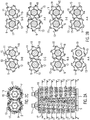
- the FIG. 1 shows a multi-range twin-shaft cutting system 100 according to the present invention.
- the multi-range twin-shaft cutting system 100 according to FIG. 1 shows two separate shafts 1 and 3, which are surrounded by a cylindrical roller body. It is understood that the shape of the roll body around the shaft can also have a different geometric shape, for example, hexagonal or octagonal.
- connection elements / couplings 5 and 7 are shown. In the illustrated arrangement of the cutting system 100 in FIG FIG. 1 the connection element / the coupling 5 for the left shaft 1 and the connection element / the coupling 7 for the right shaft 3 are shown.
- the two shafts 1 and 3 are arranged substantially parallel. The two shafts 1 and 3 are driven in opposite directions. For FIG.
- FIG. 1 shows for the cutting system 100 further support members 9 and 11, which are provided axially to the longitudinal axis of the shaft. It should be the in FIG. 1 shown number of eight support elements 9 or 11 per shaft to be understood as purely exemplary.
- the support elements 9 and 11 are provided spaced apart in the axial direction. In the present example, the distances in the axial direction are substantially uniform.
- the support members 9 and 11 of the shafts are typically formed to have a wavy or rosette-shaped circumferential or circumferential region.
- the undulating peripheral line promotes a better circulation of the material to be shredded and facilitates or optimizes at the same time the collection.
- the optimized circulation and the improved intake can reduce the energy required for shredding.
- the waveform is typically uniform, that is symmetrical about the circumference, and an unbalanced arrangement can be provided to improve the pull-in behavior.
- n The number of maxima of the waveshape of the support elements is denoted by n, for example, where n is a natural number.
- the FIG. 1 further shows cap-like protective elements 27 and 29, which are attached to the support elements 9, 11 of the left shaft 1 and the right shaft 3, respectively.
- the protective elements 27 and 29 are in FIG. 1 by way of example in the region of the smallest distance of the waveform to the center of the support elements 9 and 11 is provided.
- the protective elements 27 and 29 may be plugged or suitably fastened to the support elements 9, 11, as may also be provided instead of the protective elements 27 and 29, another suitable wear protection, such as, for example, build-up welding.
- the width of the distance between two adjacent support elements 9 of the shaft 1 or two adjacent support elements 11 of the shaft 3 is as follows and will be explained from the perspective of the shaft 1, so the left shaft.
- separating elements 17 are provided on the support elements 9 separating elements 17 are provided.
- the partition members 17 are provided so that they can engage in the opposite rotation of the shafts 1 and 3 in the space between two adjacent support members 11 of the other shaft.
- the gap between two adjacent support elements 9 ,.11 is thus at least as wide as the width of the separating elements 17 and 19.
- a separator 17 of the left shaft, in FIG. 1 is provided on the first support member 9 of the shaft 1, in the space between the first and second support member 11, that is, immediately adjacent support members, the right shaft 3 engage.
- the intervention happens during the opposite driving of the waves 1 and 3.
- the support elements 9, 11 of the right and left shaft each have a six-symmetry. This six-symmetry, for example, when looking at the connection elements / couplings 5 and 7 in FIG. 1 clear.
- the six-symmetry is also shown by the number of maximums of the waveform of the peripheral line of the support members 9, 11, as described above.
- the separating elements 17 and 19 are each mounted substantially tangentially on the peripheral region of the support elements 9 and 11. In FIG.
- each of the six separating elements 17, 19 which in FIG. 1 are each mounted on a support member 9, 11, can engage in the corresponding space between two immediately adjacent support members 11, 9 of the respective other shaft.
- each separating element 17, which is mounted on the connection element / from the coupling 5 of the left shaft 1 forth first support member 9, in the space between the first and second support member 11 of the right shaft 3, from the connection element / from the coupling 7 seen, can intervene. It is understood that corresponding correspondences apply to all other support elements 9, 11 and dividing elements 17, 19 of the respective left and right shaft 1, 3.
- n 6
- n 4 or another number.
- the separators of the left shaft are designated by the reference numeral 17.
- the separating elements of the right shaft are designated by the reference numeral 19.
- catch elements for example in the form of knives or fishing hooks are provided, which are designated by the reference numeral 13 are. Accordingly, catch elements are provided on the support elements 11 of the right shaft 3, which are designated by the reference numeral 15. In the axial direction are in FIG. 1 the catch elements 13 and 15 are provided only on some of the support elements 9, 11. It is understood, however, that catch elements 13, 15 can be provided both on some and on all support elements 9, 11. Purely by way of example are in FIG. 1 only on every third support element 9, 11, the catch elements 13, 15 are provided. The catch elements 13 and 15, respectively, improve the intake of material into the multi-shaft cutting system 100.
- the catch elements 13 and 15 can be provided on every second separation element of a support element 9, 11.
- the catch elements 13, 15 separately or it may be provided there a special separator, which results in a combination of catch element and separating element.
- the catch elements 13 and 15 are for example hook-like, knife-like or sickle-shaped, based on the normal direction of rotation.
- the arrangement of some catch elements 13 and 15 against the normal direction of rotation can be provided so that in a blockage of the waves 1 and 3 and required reverse run, the feed material, which has led to the blockage, can be loosened. This should be understood that in the FIG.
- the left shaft 1 in the clockwise direction and the right shaft 3 rotates counterclockwise thereto.
- the material to be crushed is then supplied to the cutting system 100 in accordance with the direction of rotation of the shafts 1, 3 above the two shafts.
- a pull-in or inlet region is thus defined, for example, by an imaginary plane through both longitudinal axes of the two shafts 1, 3.
- the area above this imaginary plane is to be referred to as a catchment area.
- the hook-like, knife-like or sickle-like shape of the catch elements 11, 15 improves the entry into the catchment area.
- an outlet region is provided relative to the direction of rotation of the shafts 1, 3.
- the FIG. 1 further shows counterparts 21 of the left shaft 1 and 23 of the right shaft 3.
- the divisional elements 21 and 23, respectively, also correspond to those in FIG FIG. 1 shown six-symmetry.
- the divisional elements 21, 23 are arranged such that they correspond to the separating elements 17, 19 of the support elements 9, 11 of the respective other shaft.
- the counterparts 21 of the left shaft correspond to the dividers 19 of the right shaft.
- the counterparts 23 of the right shaft correspond to the dividers 17 of the left shaft.
- a separate separating element 21, 23 can therefore be interrupted within the intermediate space in the axial direction. You can also call such a separating element as two or more parts. It is important, however, that the separate separating element 21, 23, in one-part or multi-part form corresponds in each case to the corresponding separating element 17, 19 of the respective other shaft.
- the dividing elements 17 and 19 may be chamfered at their leading edge, ie the edge, which, with respect to the direction of rotation, is substantially first in contact with the material to be comminuted, as in the following Figures 3A-3C shown. Likewise, the front edge of the respective separating elements 17, 19 have an angle against the longitudinal direction of the shaft 1, 3.
- This angle can be between 0 ° and 90 °, preferably between 0 ° and 45 °.
- the support elements 9 respectively 11 of the left and the right shaft 1, 3 are each offset by a few degrees against each other. This arrangement is also clear in the following figures. As a result, the intake and crushing movement of the shaft 1, 3 is further supported.
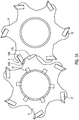
- FIG. 2 shows in three sub-figures 2A, 2B, 2C views and sections of the cutting system 100 as in FIG. 1 shown.
- FIG. 2A is shown in a plan view of the cutting system 100 with the waves 1 and 3.
- FIG. 2B is exemplified eight sections perpendicular (transverse) to the longitudinal axis of both shafts 1 and 3, which are designated AA, BB, ..., HH, shown individually.
- catch elements / teeth 13 of the left shaft 1 and catch elements 15 of the right shaft 3 are provided on support elements 9 of the left shaft and support elements 11 of the right shaft.
- HH is in each case a shown support member 11 of the right shaft 3 in front of a shown support member 9 of the left shaft.
- a total of 12 catch elements 13 and 15 are shown.
- the Figure 2C shows a view in the longitudinal direction of the shafts 1 and 3 with a view of the connecting elements / couplings 5 and 7. In this case the arrangement of the knife 19 and catch elements 15 of the right shaft 3 and the arrangement of the knife 17 and catch elements 13 of the left shaft 1 is clearly visible.
- FIGS. 3A to 3C show the within one revolution solely by the arrangement of the support member 9, 11, the dividing elements 17, 19 and the counterparts 21, 23 resulting correspondences and their respective effects.
- the catch elements 13, 15 have been omitted.
- a support element 9 of the left shaft 1 is behind a support member 11 of the right shaft.
- the outer circumference of the support element 9 of the left shaft 1 engages in the intermediate space between the support element 11 of the right shaft 3 and a support element 11 of the same shaft 3 immediately adjacent thereto.
- the dividing elements 17 and 19 show a beveled, knife-like or cutting-like region 17S or 19S.
- FIG. 3A is a catchment area of the cutting system 100 denoted by I.
- the support members 9 of the left shaft 1 and the support members 11 of the right shaft 3 engage in the opposite driving into each other.
- Two dividers 19R and 17L are designated. From the element 19R is also shown the front beveled portion 19S of the separator. It is understood that the support member 9 engages directly between the support member 11 and a directly behind the support member 11 lying further support member of the right shaft.
- the opposite movement of the two shafts 1, 3 causes the material to be shredded between the separating element 19R of the right shaft 3 and the separating element 17L of the left shaft 1 retracted, cracked and / or broken.
- This comminution thus takes place in the sectional view substantially in the axial direction.
- the wave-shaped circumferential line of the support elements 9, 11 supports this comminution process.
- the left shaft 1 continues to rotate in the clockwise direction and the right shaft 3 counterclockwise. As a result, the left support member 9 and the right support member 11 are also rotated further.
- FIG. 3B is pointed to the area II on the right separating element 19R and the corresponding left counterpart separating element 21. These come so close within the revolution that the material to be shredded is separated and / or cut between the separating element 19R of the right shaft 3 and the separating element 21 of the left shaft 1.
- the counterpart separating element 21 is shown in the shape of an aisle in the form shown here.
- an anvil shape may also be a cutting-like shape be chosen to ensure the separation in a cutting form of the material.
- the correspondence between the separating element 19, 17 and the separate separating element 21, 23 is shown here only by way of example for a separating element 19R of the right shaft 3 and corresponding separating element 21 of the left shaft 1.
- FIG. 3C shows within the same revolution corresponding to the arrangement of the separating elements 19R and 17L, another crushing operation which follows in the sequence of the second and the third crushing operation.
- the separating element 19R is the same separating element as in FIG FIG. 3B shown.
- the separating element 19R of the support element 11 of the right shaft can here work against the rear side of the separating element of the left shaft 17L, so that the material to be comminuted is again comminuted and / or cut. This repeated crushing happens in the outlet area III of the cutting system.
- a very uniform and almost overgrained final product is produced.
- the cutting system 100 may be provided within a crusher (not shown here).
- a crusher may have a funnel-like attachment, funnel, into which the material to be shredded is added.
- This funnel-like attachment may typically be provided above the catchment area of the cutting system 100.
- the fangs 13 and 15 act supportive. It is possible to provide push-pull systems which press the material to be comminuted into the hopper and thus into the comminution unit.
- a system may be provided below the cutting system 100 (not shown), a system may be provided to retain the oversized grain contained in the shredded material and to discharge it accordingly and move it away from the cutting system 100 via a conveyor belt for further use, for example.
- the cutting system 100 can be provided in a mobile, semi-mobile or stationary crusher.
Landscapes
- Engineering & Computer Science (AREA)
- Food Science & Technology (AREA)
- Environmental & Geological Engineering (AREA)
- Crushing And Pulverization Processes (AREA)
Description
Die vorliegende Erfindung betrifft ein Mehrbereichs-Zweiwellen-Schneidsystem zur Zerkleinerung von Material insbesondere in Form von Abfallprodukten.The present invention relates to a multi-range twin-shaft cutting system for comminuting material, especially in the form of waste products.
Gewerbeabfall, Industrieabfall, Hausabfall, Produktionsabfälle wie z.B. (Hart-) Kunststoff, Textilien, Verbundstoffe, Gummi, Holz, Althölzer (wie Paletten und Spanplatten), Biomasse, Strauchwerk, Haus- und Baumischabfall etc. bedürfen vor ihrer endgültigen Entsorgung oder insbesondere vor der Rückführung in den Wertstoffkreislauf und für die Energiegewinnung, der Zerkleinerung. Zur Zerkleinerung sind in dem Stand der Technik Ein- oder Mehrwellenzerkleinerer bekannt, welche beispielsweise durch Radlader, Gabelstapler oder Förderbänder über einen Trichter zur Materialaufgabe beschickt werden.Commercial waste, industrial waste, household waste, production waste such as (Hard) plastic, textiles, composites, rubber, wood, waste wood (such as pallets and chipboard), biomass, shrubbery, domestic and Baumischabfall etc. require before their final disposal or in particular before returning to the recycling and energy recovery, shredding. For comminution, single or multi-shaft shredders are known in the prior art, which are charged for example by wheel loaders, forklifts or conveyor belts via a hopper for material application.
Das zu zerkleinernde Material wird beispielsweise mittels Einzugselementen in den Trennbereich der Wellen gefördert und dort bearbeitet.The material to be crushed is conveyed for example by means of intake elements in the separation region of the waves and processed there.
Die
Die
Die
Die
Aufgrund von brechenden Werkzeugen entsteht bei der Zerkleinerung nach dem Stand der Technik ein hoher, heute nicht mehr zeitgemäßer Energiebedarf / Energieaufwand. Weiterhin folgt aufgrund eines groben, undefiniertem Zerkleinern im Endprodukt einen hohen Anteil an unerwünschtem Überkorn. Dieses erschwert die weitere Verarbeitung und eine Vermarktung des Zerkleinerungsgutes.Due to refracting tools, comminution according to the state of the art results in a high, no longer contemporary energy requirement / expenditure of energy. Furthermore, due to a coarse, undefined crushing in the final product follows a high proportion of unwanted oversize. This complicates the further processing and marketing of the shredded material.
Weiterhin gibt es nach dem Stand der Technik schneidende Zerkleinerungssysteme auch im Zweiwellenprinzip. Diese haben jedoch das Problem, dass sich der Durchsatz enorm verringert, da die Werkzeuge enger gebaut werden müssen, um einen hohen Anteil an Ausreißern, also unerwünschten Überkorn, zu vermeiden.Furthermore, according to the state of the art, cutting shredding systems also exist in the two-shaft principle. However, these have the problem that the throughput is reduced enormously, since the tools must be built closer to avoid a high proportion of outliers, so unwanted oversize grain.
Ferner gibt es das Problem, dass der Verschleiß innerhalb einer Zerkleinerungseinheit durch blockierendes, schleifendes Material drastisch erhöht, die Standzeit hierdurch stark reduziert wird.Furthermore, there is the problem that the wear within a crushing unit drastically increases due to blocking, abrasive material, the service life is thereby greatly reduced.
All diese Systeme haben lediglich 1 - 2 Trennebenen oder Trennvorgänge innerhalb eines Durchgangs, also einer Umdrehung der Zerkleinerungswerkzeuge, und sind somit häufig nicht wirtschaftlich genug.All these systems have only 1 - 2 parting lines or separation processes within a passage, so a revolution of the crushing tools, and are thus often not economical enough.
Es ist Aufgabe des neuen Mehrbereichs-Zweiwellen-Zerkleinerungssystems, angesichts der oben diskutierten Probleme des Standes der Technik, ein Mehrbereichs-Zweiwellen-Zerkleinerungssystem, ein wirtschaftlicheres und effizienteres, insbesondere Energieeffizienteres Zerkleinerungssystem bereitzustellen, worin die Effizienz der Zerkleinerung eines Durchgangs, also in einer Umdrehung der Zerkleinerungswerkzeuge, erhöht wird. Ferner soll bei dem System der Verschleiß an dem Zerkleinerungssystem und den Zerkleinerungswerkzeugen gegenüber dem Stand der Technik vermindert werden.It is an object of the novel multigrade two-shaft crushing system, in view of the above-discussed problems of the prior art, to provide a multigrade two-shaft crushing system, a more economical and efficient, in particular more energy-efficient, crushing system, wherein the efficiency of crushing one pass, ie in one revolution the crushing tools is increased. Further, the system is expected to reduce wear on the shredding system and shredding tools over the prior art.
Die obige Aufgabe wird mit einem Mehrbereichs-Zweiwellen-Schneidsystem gemäß Anspruch 1 gelöst.The above object is achieved with a multi-range twin-shaft cutting system according to claim 1.
Die Erfindung stellt ein Mehrbereichs-Zweiwellen-Schneidsystem zum Zerkleinern von Material bereit, umfassend: zwei im Wesentlichen parallel angeordnete, gegenläufig angetriebene Wellen, wobei jede Welle jeweils von einem Walzenkörper umgeben ist; eine Vielzahl von Tragelementen, wobei jedes Tragelement im Wesentlichen radial um den Walzenkörper angebracht ist, wobei vorzugsweise jedes Tragelement eine radial, wellenförmig, gerundet oder eckig bzw. kantig ausgebildete Umfangslinie aufweist; eine Vielzahl von Trennelementen, die scheiben- und / oder plattenartig ausgebildet sind, die jeweils im Wesentlichen tangential am Umfangsbereich der Tragelemente angebracht sind; wobei die Tragelemente um die Walzenkörper derart beabstandet angeordnet sind, dass jeweils ein Trennelement an einem Tragelement der einen Welle zwischen zwei unmittelbar benachbarten Tragelementen der anderen Welle eingreift; wobei für jede Welle jeweils zwischen zwei unmittelbar benachbarten Tragelementen dieser Welle auf dem Walzenkörper der Welle Gegentrennelemente angebracht sind, die zu den Trennelementen der anderen Welle derart korrespondierend angebracht sind, dass die Trennelemente der anderen Welle bei gegenläufigem Eingreifen in den Zwischenraum der beiden unmittelbar benachbarter Tragelemente der einen Welle gegen die korrespondierenden Gegentrennelemente schneidend und / oder brechend arbeiten, so dass das Material zerkleinert wird; wobei jeweils die Trennelemente der einen Welle derart korrespondierend zu den Trennelementen der anderen Welle angeordnet sind, dass bei gegenläufigem Eingreifen der Trennelemente der Wellen ein Trennelement der einen Welle gegen ein korrespondierendes Trennelement der anderen Welle schneidend arbeitet, wobei die Vorderkante des Trennelementes der einen Welle gegen die der Vorderkante des anderen Trennelements der anderen Welle abgewandten Kante arbeitet. Die beiden gegenläufig angetriebenen Wellen sind typischerweise parallel in einem Abstand angeordnet, so dass die Trennelemente der einen Welle zwischen zwei unmittelbar benachbarte Tragelemente der anderen Welle eingreifen können. Zwischen den beiden Wellen entsteht dadurch ein Spalt, in dem die Zerkleinerung des zu zerkleinernden Materials geschieht. Es versteht sich, dass die jeweiligen Trennelemente der einen Welle die äußere Oberfläche des Walzenkörpers dabei nicht erreichen. Der Walzenkörper kann dabei auch eine andere Geometrie aufweisen, etwa eine polygonale Geometrie, beispielsweise sechseckig oder achteckig. Es versteht sich ferner, dass beim gegenläufigen Eingreifen auch zumindest die äußeren Bereiche jeweils eines Trennelements der einen Welle in den Zwischenraum zwischen zwei unmittelbar benachbarte Tragelemente der anderen Welle eingreifen. Die Tragelemente sind typischerweise scheibenartig ausgebildet. Die gegenläufige Antriebsrichtung der beiden Wellen definiert beispielsweise einen Einzugsbereich des Systems etwa oberhalb einer gedachten Ebene, die durch die beiden Längsachsen der Wellen gelegt wird und einen Auslaufbereich unterhalb dieser Ebene, wobei diese Bereiche etwa nach oben durch den Beginn des gegenläufigen Eingreifens, nach unten etwa durch das Ende des gegenläufigen Eingreifens zwischen den beiden Wellen begrenzt werden.The invention provides a multi-section twin-shaft cutting system for crushing material, comprising: two substantially parallel, counter-rotating shafts, each shaft being surrounded by a roller body; a plurality of support elements, each support element being mounted substantially radially around the roller body, wherein preferably each support element has a radially, wavy, rounded or angular or edged circumferential line; a plurality of separating elements, which are disc-and / or plate-like, which are each mounted substantially tangentially on the peripheral region of the support elements; wherein the support elements are arranged spaced around the roller body such that in each case a separating element engages on a support element of a shaft between two immediately adjacent support elements of the other shaft; wherein for each shaft between each two adjacent support elements of this wave on the roller body of the shaft counterparts are attached, which are mounted correspondingly to the separating elements of the other shaft, that the separating elements of the other shaft in opposite engagement in the space of the two immediately adjacent support members cutting and / or fracturing a shaft against the corresponding counterpart dividing elements so that the material is comminuted; wherein in each case the separating elements of a shaft are arranged so corresponding to the separating elements of the other shaft, that in counter-engagement of the separating elements of the waves, a separating element of a shaft against a corresponding separating element of the other shaft cutting works, the leading edge of the separating element of a shaft against the front edge of the other separating element of the other shaft facing away from the edge works. The two oppositely driven shafts are typically arranged in parallel at a distance, so that the separating elements of a shaft can engage between two directly adjacent support elements of the other shaft. This creates a gap between the two shafts, in which the comminution of the material to be shredded happens. It is understood that the respective separating elements of a shaft do not reach the outer surface of the roller body. The roll body can also have a different geometry, such as a polygonal geometry, such as hexagonal or octagonal. It is further understood that in the opposite intervention and at least the outer regions of each of a separating element of a wave in the space between engage two immediately adjacent support elements of the other shaft. The support elements are typically formed like a disk. The opposite drive direction of the two waves defines, for example, a catchment area of the system approximately above an imaginary plane, which is laid by the two longitudinal axes of the waves and a discharge area below this level, these areas approximately upwards by the beginning of the counter-engagement, downwards approximately be limited by the end of the opposing engagement between the two waves.
Die tangential an den Tragelementen angeordneten Trennelemente der einen Welle können insbesondere in ihrer Funktion wirkungsvoll unterstützt werden durch Gegentrennelemente, die sich korrespondierend angeordnet auf dem Walzenkörper der anderen Welle befinden. So kann ein Trennelement gegen ein Gegentrennelement arbeiten. Dabei soll der Begriff arbeiten bedeuten, dass zwischen dem Trennelement und dem korrespondierenden Gegentrennelement Material zerkleinert, insbesondere geschnitten wird. Dabei soll der Begriff korrespondierende Anordnung bedeuten, dass die Anordnung der genannten Elemente, d.h. Trennelemente, Gegentrennelement, Tragelemente, es ermöglicht, dass bei gegenläufiger Drehung der Wellen sich diese Elemente derart nahe kommen, dass Material zwischen diesen Elementen zerkleinert wird. Dabei gibt es typischerweise für jedes Trennelement ein entsprechendes Gegentrennelement. Es versteht sich dabei, dass das Gegentrennelement aus einem Stück gefertigt sein kann, es aber auch möglich ist, dass Gegentrennelement aus mehreren Stücken zusammengesetzt auszubilden. Es versteht sich, dass eine Mehrzahl von Trennelementen typischerweise symmetrisch am Umfangsbereich der Tragelemente angebracht sein kann. Die typischerweise scheiben-, umlaufend wellenartige Form der Tragelemente begünstigt eine bessere Umwälzung des zu zerkleinernden Materials und erleichtert oder optimiert gleichzeitig den Einzug des Materials. Die Tragelemente können vorzugsweise eine wellenförmige oder rosettenförmige Umfangslinie oder Umfangsbereich aufweisen. Hierdurch kann die Umwälzung und der Einzug weiter enorm verbessert werden. Gleichzeitig wird dadurch der Energieaufwand zum Zerkleinern gesenkt. Die Zahl der Maxima der Wellenform der Tragelemente kann mit n bezeichnet werden, wobei n eine natürliche Zahl ist. Die Trennelemente können an allen oder wenigstens einigen dieser Maxima angebracht werden. Die Anzahl der Trennelemente kann beispielsweise n=4 oder n=6 entsprechend der Zahl der Maxima betragen. Es ist aber auch eine andere Zahl von Trennelementen denkbar. Die Trennelemente sind typischerweise symmetrisch, aber auch unsystematisch, um das Tragelement angebracht. Das gilt auch für Tragelemente, die beispielsweise keine Wellenform am Umfang aufweisen. Die Symmetrie n wird typischerweise für alle Tragelemente gleich sein., kann aber auch unterschiedlich gewählt werden.The separating elements of a shaft tangentially arranged on the support elements can be effectively supported, in particular in their function, by counterpart separation elements, which are arranged correspondingly arranged on the roller body of the other shaft. Thus, a separating element can work against a counterpart separating element. The term work is intended to mean that comminuted material, in particular cut between the separator and the corresponding counterpart separating element. In this case, the term corresponding arrangement is intended to mean that the arrangement of said elements, ie separating elements, counter separating element, supporting elements, it allows that in opposite rotation of the waves, these elements come so close that material is crushed between these elements. There is typically a corresponding separating element for each separating element. It goes without saying that the counterpart separating element can be made in one piece, but it is also possible for the counterpart separating element to be composed of several pieces. It is understood that a plurality of separating elements can typically be mounted symmetrically on the peripheral region of the support elements. The typically disk-shaped, circumferentially wave-like shape of the support elements promotes better circulation of the material to be shredded and at the same time facilitates or optimizes the intake of the material. The support elements may preferably have a wavy or rosette-shaped circumferential or circumferential region. As a result, the circulation and the collection can be further improved enormously. At the same time, this reduces the energy required for shredding. The number of maxima of the waveshape of the support elements can be denoted by n, where n is a natural number. The separating elements can be attached to all or at least some of these maxima. The number of separating elements can be, for example, n = 4 or n = 6, corresponding to the number of maxima. But it is also conceivable another number of separating elements. The separating elements are typically symmetrical, but also unsystematic, mounted around the supporting element. This also applies to support elements that, for example, have no waveform on the circumference. The symmetry n will typically be the same for all supporting elements, but may also be chosen differently.
In dem Mehrbereichs-Zweiwellen-Schneidsystem sind die Trennelemente der einen Welle derart korrespondierend zu den Trennelementen der anderen Welle angeordnet, dass bei gegenläufigem Eingreifen der Trennelemente der Wellen ein Trennelement der einen Welle gegen ein unmittelbar benachbartes Trennelement der anderen Welle brechend arbeitet. Die Trennelemente sind, wie oben beschrieben typischerweise derart an den Tragelementen befestigt, dass das Trennelement etwa in seiner Mitte an dem Tragelement, das dazu senkrecht steht, befestigt ist. Ein Trennelement der einen Welle ist also tangential, etwa mittig an dem Tragelement befestigt. Ein Trennelement der einen Welle, der Einfachheit halber als erstes Trennelement bezeichnet, kann zwischen zwei benachbarte Tragelemente der anderen Welle eingreifen. Diese benachbarten Tragelemente der anderen Welle tragen wiederum Trennelemente, die sich in entgegen gesetzter Richtung zu dem ersten Trennelement bewegen. Dadurch kann zwischen dem ersten Trennelement und einem benachbarten Trennelement der anderen Welle zu zerkleinerndes Material geschnitten, gerissen bzw. gebrochen werden. Diese Zerkleinerung findet typischerweise im Einzugsbereich statt. Dadurch kann das zu zerkleinernde Material bereits sehr früh gebrochen und / oder geschnitten und gerissen werden. In dem Mehrbereichs-Zweiwellen-Schneidsystem können die Trennelemente der einen Welle jeweils wenigstens an ihren Vorderkanten bezogen auf die Gegentrennelemente der anderen Welle einen Schneidbereich aufweisen, der beispielsweise abgeschrägt ist.In the multigrade two-shaft cutting system, the separators of one shaft are disposed corresponding to the separators of the other shaft so that, when the separators of the shafts engage in opposite directions, a separator of one shaft will break against an immediately adjacent separator of the other shaft. As described above, the dividing elements are typically fastened to the supporting elements in such a way that the dividing element is fastened approximately at its center to the supporting element which is perpendicular thereto. A separator of a shaft is thus tangential, approximately centrally attached to the support member. A separator of a shaft, for simplicity's sake referred to as the first separator, can engage between two adjacent support members of the other shaft. These adjacent supporting elements of the other shaft in turn carry separating elements which move in the opposite direction to the first separating element. As a result, material to be shredded can be cut, cracked or broken between the first separating element and an adjacent separating element of the other shaft. This comminution typically takes place in the catchment area. As a result, the material to be crushed can be broken and / or cut and torn very early. In the multigrade two-shaft cutting system, the partition members of one shaft may each have, at least at their leading edges with respect to the counterpart members of the other shaft, a cutting portion which is bevelled, for example.
Die scheibenartigen und / oder plattenartigen und / oder messerartigen Trennelemente können eine rechteckige, parallelogrammartige oder viereckige Form aufweisen. Es versteht sich, dass die Trennelemente typischerweise derart an den Tragelementen befestigt sind, dass das Trennelement etwa in seiner Mitte an dem Tragelement, das dazu senkrecht steht, befestigt ist. Der bei gegenläufiger Drehung der Wellen zum Spalt zeigende vordere Kantenbereich der Trennelemente, kurz als Vorderkante bezeichnet, kann durch einen Schneidbereich geeignet einen höheren Druck auf eine kleinere Fläche ausüben, so dass die Effizienz des Arbeitsvorgangs, also des Zerkleinerns durch Schneiden gegen das Gegentrennelement erhöht werden kann.The disc-like and / or plate-like and / or knife-like separating elements may have a rectangular, parallelogram-like or quadrangular shape. It is understood that the separating elements are typically fastened to the support elements such that the separating element is fastened approximately at its center to the support element which is perpendicular thereto. The front edge region of the separating elements, referred to briefly as the leading edge, which points towards the gap when the waves rotate counter to one another, can exert a higher pressure on a smaller area by means of a cutting region, so that the efficiency of the working process, ie the cutting by cutting against the counterpart separating element, is increased can.
In dem Mehrbereichs-Zweiwellen-Schneidsystem können die Trennelemente der Welle in der Breite so ausgebildet sein, dass die Breite geringfügig kleiner als der jeweilige Abstand zwischen den beiden gegenüberliegenden Tragelementen ist, so dass beim gegenläufigem Eingreifen der Trennelemente der Wellen in die gegenüber befindlichen Tragelemente, ein Trennelement der einen Welle gegen zwei unmittelbar benachbarte Tragelemente der anderen Welle brechend und / oder schneidend seitlich arbeitet. In dem Mehrbereichs-Zweiwellen-Schneidsystem können jeweils die Trennelemente der einen Welle derart korrespondierend zu den Trennelementen der anderen Welle angeordnet sein, dass bei gegenläufigem Eingreifen der Trennelemente der Wellen ein Trennelement der einen Welle gegen ein korrespondierendes Trennelement der anderen Welle schneidend arbeitet, wobei insbesondere die Vorderkante des Trennelementes der einen Welle gegen die der Vorderkante des anderen Trennelements abgewandte Kante arbeitet.In the multi-section two-shaft cutting system, the dividing elements of the shaft may be formed in width so that the width is slightly smaller than the respective distance between the two opposing support elements, so that in opposite engagement elements, the waves in the opposing support elements, a separating element of a shaft against two immediately adjacent support members of the other wave breaking and / or cutting sideways works. In the multigrade two-shaft cutting system, the separating elements of one shaft may be arranged corresponding to the separating elements of the other shaft such that, when the separating elements of the shafts engage in opposite directions, a separating element of the one shaft opposes a corresponding separating element of the other shaft is working cutting, in particular, the front edge of the separating element of the one shaft working against the front edge of the other separating element facing away from edge.
Wie oben beschrieben kann ein Trennelement der einen Welle, der Einfachheit halber als erstes Trennelement bezeichnet, zwischen zwei benachbarte Tragelemente der anderen Welle eingreifen. Diese benachbarten Tragelemente der anderen Welle tragen wiederum Trennelemente, die sich in entgegen gesetzter Richtung zu dem ersten Trennelement bewegen. Die Trennelemente der anderen Welle können derart korrespondierend zum ersten Trennelement der einen Welle angeordnet sein, dass die Vorderkante des ersten Trennelements einen Zerkleinerungsvorgang gegen die der Vorderkante des anderen Trennelements der anderen Welle abgewandte Kante, also die rückseitige Kante, ausführen kann. Dabei kommt es typischerweise zu einer Überlappung in axialer Richtung zwischen der Vorderkante des ersten Trennelements und der rückseitigen Kante des korrespondierenden Trennelements. Dies geschieht typischerweise im Auslaufbereich des Systems. Dadurch wird Material abermals zerkleinert.As described above, a partition member of one shaft, which is referred to as a first partition member for convenience, can be engaged between two adjacent support members of the other shaft. These adjacent supporting elements of the other shaft in turn carry separating elements which move in the opposite direction to the first separating element. The separating elements of the other shaft may be arranged corresponding to the first separating element of a shaft such that the front edge of the first separating element can perform a crushing operation against the edge facing away from the leading edge of the other separating element of the other shaft, ie the rear edge. In this case, there is typically an overlap in the axial direction between the front edge of the first separating element and the rear edge of the corresponding separating element. This is typically done in the outlet area of the system. As a result, material is shredded again.
In dem Mehrbereichs-Zweiwellen-Schneidsystem können jeweils die Trennelemente der einen Welle derart korrespondierend zu den Trennelementen der anderen Welle und den Gegentrennelementen der anderen Welle angeordnet sein, dass innerhalb einer einzigen gegenläufigen Umdrehung beider Wellen bei gegenläufigem Eingreifen der Trennelemente der Wellen zunächst ein Trennelement der einen Welle gegen ein unmittelbar benachbartes Paar der Tragelemente der anderen Welle schneidend und / oder brechend arbeitet, danach das Trennelement der einen Welle gegen die zu diesem Trennelement korrespondierenden Gegentrennelemente der anderen Welle schneidend arbeitet und danach das Trennelement der einen Welle gegen das Trennelement der anderen Welle das zu diesem Trennelement korrespondierend angebracht ist, gegen die der Vorderkante des anderen Trennelements abgewandte Kante, schneidend arbeitet.In the multi-range twin-shaft cutting system, the separating elements of one shaft may be arranged corresponding to the separating elements of the other shaft and the counter-separating elements of the other shaft, that within a single opposite rotation of both waves in opposite directions of the separating elements of the waves, first a separating element a shaft against a directly adjacent pair of support members of the other shaft cutting and / or breaking works, then the separating element of a shaft against the separating element corresponding to this separating elements of the other shaft cutting works and then the separating element of a shaft against the separating element of the other shaft which is mounted corresponding to this separating element, against which the front edge of the other separating element facing away edge, cutting works.
Die Anordnung der Trennelemente der einen Welle korrespondierend zu den Trennelementen der anderen Welle und korrespondierend zu den Gegentrennelementen der anderen Welle ermöglicht also innerhalb einer einzigen gegenläufigen Umdrehung der beiden Wellen vier Trennvorgänge / Zerkleinerungsvorgänge bezüglich des zu zerkleinernden Materials. Der erste Trennvorgang besteht beispielsweise darin, dass das Material zwischen einem Trennelement der einen Welle, der Einfachheit halber als erstes Trennelement bezeichnet, und einem Trennelement der anderen Welle, der Einfachheit halber als zweites Trennelement bezeichnet, eingezogen, gebrochen und gerissen werden. Der erste Trennvorgang geschieht typischerweise im Einzugsbereich der beiden Tragelementen der anderen Welle.The arrangement of the separating elements of a shaft corresponding to the separating elements of the other shaft and corresponding to the counterpart separating elements of the other shaft thus allows four separation processes / comminution processes with respect to the material to be comminuted within a single opposite rotation of the two waves. The first separation process consists, for example, in that the material is drawn, broken and torn between a separating element of one shaft, which for reasons of simplicity is referred to as a first separating element, and a separating element of the other shaft, which is referred to as a second separating element for the sake of simplicity. The first separation process typically occurs in the catchment area of the two support elements of the other shaft.
Unmittelbar danach wird das Trennelement der einen Welle, zwischen die beiden Tragelemente der anderen Welle eingeführt. Dadurch dass das Trennelemente nur geringfügig in der Breite kleiner ist, als der Abstand zwischen den Tragelementen der anderen Welle, kommt es zwischen dem Trennelement und den wellförmig ausgebildeten seitlichen Kanten des Tragelementes zu einem zweiten überwiegend brechenden, aber auch einem schneidenden und reißenden zweiten Zerkleinerungsvorgang. Dieser zweite Trenn- bzw. Zerkleinerungsvorgang erfolgt typischerweise noch im Einzugsbereich der beiden Tragelemente. Danach wird beispielsweise bei derselben gegenläufigen Umdrehung der beiden Wellen das Material zwischen dem ersten Trennelement und einem korrespondierenden Gegentrennelement der anderen Welle zerkleinert, getrennt, geschnitten. Dieser dritte Trennvorgang geschieht typischerweise auch in einem Bereich zwischen den beiden Tragelementen der anderen Welle. Danach wird beispielsweise bei derselben gegenläufigen Umdrehung der beiden Wellen das Material zwischen dem ersten Trennelement der einen Welle und dem Trennelement der anderen Welle abermals zerkleinert, etwa geschnitten. Wobei insbesondere die Vorderkante des Trennelementes der einen Welle gegen die der Vorderkante des anderen Trennelements abgewandten Kante arbeitet. Dieser vierte Trennvorgang geschieht typischerweise im Auslaufbereich des Systems. Durch die Kombination der vier Trennvorgänge kann das Material besonders effektiv und gleichmäßig zerkleinert werden. Es entsteht ein in der Körnung gleichmäßiges Endprodukt, das nahezu frei von unerwünschten Überkorn ist. Das Zerkleinerungsgut kann praktisch zur direkten Vermarktung gelangen ohne weitere komplizierte nachfolgende Technik, etwa Siebtechnik, bemühen zu müssen. Ferner wird der Energiebedarf zum Zerkleinern aufgrund des gleichmäßigen Einzugs des zu zerkleinernden Materials und der wellenartigen Form der Tragelemente stark reduziert. Ein Trennen auf vier Ebenen, also in vier Abschnitten während nur eines Durchlaufes bzw. Umdrehung der Wellen, wie oben beschrieben, reduziert den Energiebedarf, den Verschleiß und optimiert die Gleichmäßigkeit des ausgegebenen zerkleinerten Materials.Immediately afterwards, the separating element of one shaft is inserted between the two supporting elements of the other shaft. Characterized that the separating elements only slightly smaller in width than the distance between the support elements of the other shaft, it comes between the separating element and the corrugated side edges of the support element to a second predominantly refractive, but also a cutting and tearing second crushing process. This second separation or comminution process typically still takes place in the catchment area of the two support elements. Thereafter, for example, in the same reverse rotation of the two shafts, the material between the first separating element and a corresponding counterpart separating element of the other shaft comminuted, separated, cut. This third separation process typically also takes place in a region between the two support elements of the other shaft. Thereafter, for example, in the same opposite rotation of the two waves, the material between the first separator of the one shaft and the separator of the other wave again crushed, cut approximately. In particular, the front edge of the separating element of the one shaft works against the edge facing away from the front edge of the other separating element. This fourth separation process typically occurs in the discharge area of the system. By combining the four separation processes, the material can be comminuted particularly effectively and evenly. The result is a uniform in the grain end product, which is almost free of unwanted oversize. The comminuted material can reach virtually the point of commercialization without the need for further complicated downstream technology, such as screening technology. Furthermore, the energy requirement for crushing due to the uniform intake of the material to be crushed and the wave-like shape of the support elements is greatly reduced. Disconnecting on four levels, ie in four sections during only one pass of the shafts, as described above, reduces the energy requirement, the wear and optimizes the uniformity of the output shredded material.
In dem Mehrbereichs-Zweiwellen-Schneidsystem kann jedes Trennelement der einen Welle jeweils mit zwei Gegentrennelementen zweier unmittelbar benachbarter Tragelemente der anderen Welle korrespondieren, wobei die beiden Gegentrennelemente zwischen den beiden Trageelementen in axialer Richtung beabstandet sind.In the multigrade two-shaft cutting system, each separator of one shaft may correspond to two counterparts of two immediately adjacent support members of the other shaft, the two counterparts being spaced axially between the two support members.
In dem Mehrbereichs-Zweiwellen-Schneidsystem können die Gegentrennelemente unmittelbar an den Tragelementen auf dem Walzenkörper vorgesehen sein.In the multigrade two-shaft cutting system, the counterpart dividing members may be provided directly on the support members on the roll body.
Die Gegentrennelemente können praktisch direkt an den Tragelementen angeformt sein oder an den Tragelementen geeignet befestigt oder angeschweißt sein. Es versteht sich, dass die radiale Höhe der Gegentrennelemente typischerweise geringer als die radiale Höhe der Tragelemente ist.The countertraction elements can be formed virtually directly on the support elements or be suitably fastened or welded to the support elements. It goes without saying that the radial height of the counterparts is typically less than the radial height of the support elements.
In dem Mehrbereichs-Zweiwellen-Schneidsystem können die Gegentrennelemente quaderförmig oder rechteckig ausgebildet sein und insbesondere in axialer Richtung senkrecht zu den Tragelementen vorgesehen sein.In the multigrade two-shaft cutting system, the counterpart dividing elements can be cuboidal or rectangular in shape and, in particular, can be provided perpendicular to the support elements in the axial direction.
In dem Mehrbereichs-Zweiwellen-Schneidsystem können die Gegentrennelemente jeweils an ihren Vorderkanten, die zur anderen Welle zeigen, einen Schneidbereich aufweisen, der beispielsweise abgeschrägt ist.In the multigrade two-shaft cutting system, the counterpart dividers may each have, at their leading edges facing the other shaft, a cutting area which is bevelled, for example.
Die Gegentrennelemente können quaderförmig oder klötzchenartig ausgebildet sein, wodurch eine ambossartige Wirkung gegen die korrespondierenden Trennelemente erzielbar ist. Ebenso können die Gegentrennelemente ihrerseits an ihren Vorderkanten, die zur anderen Welle zeigen, einen Schneidbereich aufweisen, der beispielsweise abgeschrägt ist, so dass jeweils der Schneidbereich des Gegentrennelements und des korrespondierenden Trennelements eine Schneidwirkung erzielen können.The counterparts may be formed cuboid or like a block, whereby an anvil-like action against the corresponding separating elements can be achieved. Likewise, the counterpart separating elements in turn may have, at their leading edges facing the other shaft, a cutting area which is bevelled, for example, so that in each case the cutting area of the counterpart separating element and of the corresponding separating element can achieve a cutting action.
In dem Mehrbereichs-Zweiwellen-Schneidsystem können die Vorderkanten der Trennelemente im Wesentlichen in axialer Richtung parallel zur Längsachse der Welle angeordnet sein oder die Vorderkanten der Trennelemente mit einer Schräge unter einem Winkel α zur Längsachse der Welle angeordnet sein, wobei 0°< α < 90°, bevorzugt 0°< α < 45° ist.In the multi-section twin-shaft cutting system, the leading edges of the divider elements may be disposed substantially in the axial direction parallel to the longitudinal axis of the shaft or the leading edges of the divider elements may be inclined at an angle α to the longitudinal axis of the shaft, where 0 ° <α <90 ° °, preferably 0 ° <α <45 °.
Durch die Schräge der Vorderkanten der Trennelemente können die Trennelemente spezifischen Zerkleinerungsaufgaben angepasst werden.Due to the slope of the leading edges of the separating elements, the separating elements can be adapted to specific comminution tasks.
In dem Mehrbereichs-Zweiwellen-Schneidsystem können die zu den Trennelementen der einen Welle korrespondierenden Gegentrennelemente der anderen Welle entsprechend der Schräge der korrespondierenden Trennelemente angeordnet sein.In the multigrade two-shaft cutting system, the divisional elements of the other shaft corresponding to the partition members of one shaft may be arranged in accordance with the slope of the corresponding partition members.
Die Gegentrennelemente sind typischerweise entsprechend der Schräge der Trennelemente angeordnet, um eine möglichst hohe Effizienz zu erzeugen. Ist die Schräge 0°, d.h. die Vorderkanten der Trennelemente sind im Wesentlichen in axialer Richtung parallel zur Längsachse der Welle, so ist beispielsweise die Schräge der Gegentrennelemente ebenfalls 0°.The counterpart dividing elements are typically arranged according to the slope of the separating elements in order to produce the highest possible efficiency. If the slope is 0 °, i. the leading edges of the separating elements are substantially parallel to the longitudinal axis of the shaft in the axial direction, for example, the slope of the separating elements is also 0 °.
Das Mehrbereichs-Zweiwellen-Schneidsystem kann ferner eine Vielzahl von Fangelementen umfassen, die an wenigstens einigen der Tragelemente an deren Außenumfang im Wesentlichen radial zur Längsachse der Welle angebracht sein können, wobei die Fangelemente typischerweise hakenartig gebogen sind, so dass sie überwiegend auf die jeweils andere Welle zeigen.The multi-range twin-shaft cutting system may further include a plurality of catch elements that may be attached to at least some of the support members at its outer periphery substantially radially to the longitudinal axis of the shaft, wherein the catch elements are typically bent like a hook, so that they predominantly on the other Wave show.
Die Fangelemente können beispielsweise an jedem zweiten oder dritten Tragelement vorgesehen werden. Es können für ein Tragelement mit Fangelementen die Fangelemente an allen oder wenigstens an einigen der Trennelemente vorgesehen sein. Dabei können die Fangelemente etwa an der Position der Trennelemente mittig zu den Trennelementen vorhanden sein. Es versteht sich, dass die Fangelemente so ausgebildet sind, dass sie die Oberfläche des Walzenkörpers der anderen Welle bei Drehung der Wellen nicht berühren. Die Fangelemente verbessern das Einziehen von unzerkleinertem Material in den Einzugsbereich der beiden Wellen.The catch elements can be provided, for example, on every second or third support element. It may be provided on all or at least some of the separating elements for a support element with catch elements, the catch elements. In this case, the catching elements may be present approximately at the position of the separating elements in the middle of the separating elements. It is understood that the catch elements are formed so that they do not touch the surface of the roller body of the other shaft upon rotation of the waves. The catch elements improve the feeding of uncut material into the catchment area of the two shafts.
In dem Mehrbereichs-Zweiwellen-Schneidsystem können die Tragelemente jeweils an ihrem zum Wellenmittelpunkt kleinsten Abstand ein Schutzelement oder einen sonstigen geeigneten Verschleißschutz aufweisen, die jeweils zur anderen Welle zeigen.In the multi-range twin-shaft cutting system, the support elements may each have a protective element or other suitable wear protection at their smallest distance to the shaft center point, which point in each case to the other shaft.
Das Schutzelement, Verschleißschutz oder spezielles Verschleißelement an den Tragelementen ist typischerweise an dem Mittelpunkt am nächsten kommenden Punkt angebracht, und zwar an der wellenförmig ausgebildeten Schmalseite der Tragelemente und dient beispielsweise dazu, diesen Punkt zu schützen, da dieser Punkt am stärksten durch den Zerkleinerungsvorgang beansprucht wird,The protective element, wear protection or special wear element on the support elements is typically attached to the mid-point closest to the wavy narrow side of the support elements and serves, for example, to protect this point, since this point is most heavily stressed by the comminution process .
In dem Mehrbereichs-Zweiwellen-Schneidsystem können die beiden Wellen synchron oder asynchron angetrieben werden, wobei jede der Wellen auswechselbar ist.In the multi-range twin-shaft cutting system, the two shafts can be driven synchronously or asynchronously, with each of the shafts being interchangeable.
Dabei ist hier besonders die Breite der Trag- und Trennelemente für den Asynchronlauf entscheidend. In dem Mehrbereichs-Zweiwellen-Schneidsystem kann jede der beiden Wellen über ein Getriebe hydraulisch oder mechanisch oder durch einen Direktantrieb angetrieben werden.Here, especially the width of the support and separating elements for the asynchronous is crucial. In the multi-range twin-shaft cutting system, each of the two shafts can be driven via a transmission hydraulically or mechanically or by a direct drive.
Durch das synchrone oder asynchrone Antreiben kann den verschiedenen Lasten, die auf die Wellen bei der Umdrehung wirken, Rechnung getragen werden. Ein Getriebe oder ein Direktantrieb kann die entsprechende Kraftübertragung hydraulisch oder mechanisch gewährleisten.By synchronous or asynchronous driving, account can be taken of the various loads acting on the shafts during the revolution. A gearbox or a direct drive can ensure the corresponding power transmission hydraulically or mechanically.
Die Erfindung stellt ferner eine Zerkleinerungsvorrichtung zum Zerkleinern von Material bereit, umfassend: ein Gehäuse; eine Trichtervorrichtung zum Einfüllen des Materials; ein Mehrbereichs-Zweiwellen-Schneidsystem wie oben beschrieben; einen motorischen Antrieb, insbesondere einen Stellmotor oder einen Torquemotor, insbesondere einen Elektro- oder Dieselmotor, zum Antreiben der Wellen und einen Austragbereich zum Austragen des zerkleinerten Materials, wobei vorzugsweise der Austragsbereich als Förderband, Schieber, Klappe oder Kratzförderer ausgeführt ist.The invention further provides a shredder for shredding material, comprising: a housing; a hopper device for filling the material; a multi-range twin-shaft cutting system as described above; a motor drive, in particular a servo motor or a torque motor, in particular an electric or diesel engine, for driving the shafts and a discharge for discharging the crushed material, wherein preferably the discharge is designed as a conveyor belt, slide, flap or scrape conveyor.
Es gilt also: In dem neuen Mehrbereichs-Zweiwellen-Zerkleinerungssystem ergeben sich aufgrund der Geometrie und der Trennelemente Anordnungen, 4 Trennvorgänge / Trennebenen innerhalb eines Durchgangs, also bei einer Umdrehung der gegenläufigen Wellen, wodurch der Zerkleinerungsvorgang deutlich effizienter wird.Thus, the following applies: in the new multigrade two-shaft comminution system, due to the geometry and the separating elements, there are arrangements, 4 separating processes / parting planes within one pass, ie one revolution of the counterrotating shafts, whereby the comminution process becomes significantly more efficient.
Weitere Merkmale und beispielhafte Ausführungsformen der vorliegenden Erfindung werden nachfolgend anhand der Zeichnungen näher erläutert. Es versteht sich, dass die Ausführungsformen nicht den Bereich der vorliegenden Erfindung erschöpfen. Es versteht sich weiterhin, dass einige oder sämtliche der im Weiteren beschriebenen Merkmale auch auf andere Weise miteinander kombiniert werden können.
-
Figur 1 stellt eine Prinzipskizze für ein Mehrbereichs-Zweiwellen-Schneidsystem gemäß der vorliegenden Erfindung dar. -
Figur 2A stellt eine schematische Draufsicht auf das Mehrbereichs-Zweiwellen-Schneidsystem gemäßFigur 1 dar. -
Figur 2B stellt schematische Schnitte quer zur Längsrichtung durch das Schneidsystem ausFigur 2A dar. -
Figur 2C stellt einen Blick in Längrichtung der Wellen des Schneidsystems ausFigur 2A dar. -
Figuren 3A - 3C zeigen schematisch die spezifische Anordnung von Trageelementen, Trennelementen und Gegentrennelementen im Hinblick auf die Zerkleinerung von Material.
-
FIG. 1 FIG. 12 illustrates a schematic diagram of a multi-range two-shaft cutting system according to the present invention. FIG. -
FIG. 2A provides a schematic plan view of the multi-range twin-shaft cutting system according toFIG. 1 represents. -
FIG. 2B presents schematic sections across the longitudinal direction through the cutting systemFIG. 2A represents. -
Figure 2C takes a look in the longitudinal direction of the waves of the cutting systemFIG. 2A represents. -
FIGS. 3A-3C schematically show the specific arrangement of supporting elements, separating elements and counterpart dividing elements with regard to the comminution of material.
Die
Die
Die Breite des Abstandes zwischen zwei benachbarten Tragelementen 9 der Welle 1 oder zwei benachbarten Tragelementen 11 der Welle 3 ist wie folgt und wird aus der Sicht der Welle 1, also der linken Welle erläutert. An den Tragelementen 9 sind Trennelemente 17 vorgesehen. Die Trennelemente 17 sind derart vorgesehen, dass sie beim gegenläufigen Antreiben der Wellen 1 und 3 in den Zwischenraum zwischen zwei benachbarten Tragelementen 11 der anderen Welle eingreifen können. Der Zwischenraum zwischen zwei benachbarten Tragelementen 9 bzw.11 ist also mindestens so breit wie die Breite der Trennelemente 17 und 19. Bei Ausbildung der Trennelemente 17 und 19 in geringfügig kleinerer Breite, die dem Abstand zwischen den beiden Tragelementen 9 bzw. 11 entspricht, erfolgt auch eine seitliche Zerkleinerung zwischen den Trag- und Trennelementen. Dies gilt umgekehrt auch für Trennelemente 19, die von den Tragelementen 11 der Welle 3 getragen werden. Beispielsweise kann also ein Trennelement 17 der linken Welle, das in
Weiterhin bringt es beim Einzug des zu zerkleinernde Material in das Mehrbereichs-Zweiwellen-Schneidsystem 100 einen Vorteil, wenn es auch zwischen den ansonsten im gleichen Winkelabstand angeordneten Trennelementen 17 und 19, durch einen größeren Winkelabstand eine größere Lücke, oder mehrere große Lücken gibt.Furthermore, it brings an advantage when pulling the material to be shredded in the multi-range twin-
Das heißt, dass der Winkelabstand zwischen zwei oder mehreren Trennelementen 17 an den Tragelementen 9 bezogen auf den Umfang der Welle 1, größer als bei den anderen Trennelementen 17 ist.That is, the angular distance between two or
Ebenso ist der Winkelabstand der jeweils zur Welle 1 korrespondierenden Trennelemente 19 der Tragelemente 11 der Welle 3, jeweils bezogen auf den Umfang der Welle 3, größer als der Winkelabstand der anderen im gleichen Winkelabstand angeordneten Trennelemente 19 der Welle 3.Similarly, the angular distance of each corresponding to the shaft 1
Es ist selbstverständlich, dass die jeweiligen Gegentrennelemente 21 und 23 der Wellen 1 und 3 in dem gleichen korrespondierenden Winkelabstand der Trennelementen 17 und 19 der Wellen 1 und 3 angeordnet werden.It goes without saying that the
Der Abstand beträgt also in diesem Beispiel in etwa 60°. Jedes der sechs Trennelemente 17, 19 die in
An den Tragelementen 9 der linken Welle 1 sind außerdem Fangelemente, beispielsweise in Form von Messern oder Fanghaken, vorgesehen, die mit dem Bezugszeichen 13 bezeichnet sind. Entsprechend sind an den Tragelementen 11 der rechten Welle 3 Fangelemente vorgesehen, die mit dem Bezugszeichen 15 bezeichnet sind. In axialer Richtung sind in
Die
Die
In den Schnittansichten der
In der
In
Es versteht sich, dass das Schneidsystem 100 gemäß
Claims (16)
- Multi-region twin-shaft cutting system (100) for comminuting material, comprising:two shafts (1, 3) which are arranged substantially parallel and are driven in an opposite manner, wherein each shaft (1, 3) is in each case surrounded by a roll body;a multiplicity of supporting elements (9, 11), wherein each supporting element (9, 11) is fitted substantially radially around said roll body, wherein each supporting element (9, 11) preferably has a radial, shaft-like, rounded or angular or edged, circumferential line;a multiplicity of severing elements (17, 19) which are of disc- and / or plate-like design and are each fitted substantially tangentially to the circumferential region of said supporting elements (9, 11);wherein said supporting elements (9, 11) are arranged at a distance around said roll bodies in such a manner that in each case one severing element (17, 19) on one supporting element (9, 11) of said one shaft (1, 3) engages between two directly adjacent supporting elements (11, 9) of said other shaft (3, 1);wherein, for each shaft (1, 3), counter severing elements (21, 23) are fitted in each case between two directly adjacent supporting elements (9, 11) of said shaft (1, 3), on said roll body of said shaft (1, 3), said counter severing elements being fitted in a corresponding manner to said severing elements (17, 19) of said other shaft (3, 1) such that said severing elements (17, 19) of said other shaft (3, 1), on opposite engagement in the intermediate space of said two directly adjacent supporting elements (9, 11) of said one shaft (1, 3), operate counter to said corresponding counter severing elements (21, 23), in a cutting and / or breaking manner, such that said material is comminuted; characterized in thatsaid severing elements (17, 19) of said one shaft (1, 3) are each arranged in corresponding manner to said severing elements (19, 17) of said other shaft (3, 1) such that, on opposite engagement of said severing elements (17, 19) of said shafts (1, 3), a severing element (17, 19) of said one shaft (1, 3) operates in a cutting manner counter to a corresponding severing element (19, 17) of said other shaft (1, 3), where said leading edge of said severing element (17, 19) of said one shaft (1, 3) operates counter to the edge facing away from said leading edge of said other severing element (19, 17).
- Multi-region twin-shaft cutting system (100) according to claim 1, wherein said severing elements (17, 19) of said one shaft (1, 3) each at least at their leading edges relative to said counter severing elements (21, 23) of said other shaft (3, 1) comprise a cutting area (17S, 19S) which is, for example, beveled.
- Multi-region twin-shaft cutting system (100) according to at least one of the claims 1 - 2, wherein said severing elements (17, 19) of said shaft (1, 3) are in their width formed such that said width is slightly smaller than the respective distance between said two oppositely disposed supporting elements (9, 11), so that on opposite engagement of said severing elements (17, 19) of said shafts (1, 3) with said oppositely disposed supporting elements (9, 11), a severing element (17, 19) of said one shaft (1, 3) operates in a breaking and / or cutting manner laterally counter to two directly adjacent supporting elements (9, 11) of said other shaft (3, 1).
- Multi-region twin-shaft cutting system (100) according to at least one of the claims 1 - 3, wherein said severing elements (17, 19) of said one shaft (1, 3) are each arranged in corresponding manner to said severing elements (19, 17) of said other shaft (3, 1) such that, on opposite engagement of said severing elements (17, 19) of said shafts (1, 3), a severing element (17, 19) of said one shaft (1, 3) operates in a breaking manner counter to a directly adjacent severing element (19, 17) of said other shaft (3, 1).
- Multi-region twin-shaft cutting system (100) according to at least one of the claims 1 - 4, wherein said severing elements (17, 19) of said one shaft (1, 3) are each arranged in corresponding manner to said severing elements (19, 17) of said other shaft (3, 1) and said counter severing elements (23, 21) of said other shaft (3, 1) such that, during a single opposite rotation of both shafts (1, 3) on opposite engagement of said severing elements (17, 19) of said shafts (1, 3), initially one severing element (17, 19) of said one shaft (1, 3) operates counter to a directly adjacent pair of supporting elements (17, 19) of said other shaft (3). During the same rotation of both shafts (1, 3) on opposite engagement of said severing elements (17, 19) of said shafts (1, 3), initially one severing element (17, 19) of said one shaft (1, 3) operates in a cutting and / or breaking manner laterally counter to a directly adjacent pair of supporting elements (9, 11) of said other shaft (3, 1), then said severing element (17, 19) of said one shaft (1, 3) operates in a cutting manner counter to said counter severing elements (23, 21) of said other shaft (3, 1) corresponding to said severing element (17, 19), and then said severing element (17, 19) of said one shaft (1, 3) operates in a cutting manner counter to said severing element (19, 17) of said other shaft (3, 1) which is fitted in a corresponding manner to said severing element (17, 19), counter to said edge facing away from said leading edge of said other severing element (19, 17).
- Multi-region twin-shaft cutting system (100) according to at least one of the claims 1 - 5, wherein each severing element (17, 19) of said one shaft (1, 3) corresponds to two counter severing elements (23, 21) of two directly adjacent supporting elements (11, 9) of said other shaft (3, 1), wherein said two counter severing elements (23, 21) are spaced in the axial direction between said two supporting elements (11, 9).
- Multi-region twin-shaft cutting system (100) according to at least one of the claims 1 - 6, wherein said counter severing elements (21, 23) are provided directly at said supporting elements (9, 11) on said roll body.
- Multi-region twin-shaft cutting system (100) according to at least one of the claims 1 - 7, wherein said counter severing elements (21, 23) are ashlar-shaped or rectangular and in particular provided in the axial direction perpendicular to said supporting elements (9, 11).
- Multi-region twin-shaft cutting system (100) according to at least one of the claims 1 - 8, wherein said counter severing elements (21, 23) each at their leading edges facing said other shaft comprises a cutting area which is, for example, beveled.
- Multi-region twin-shaft cutting system (100) according to at least one of the claims 1 - 9, wherein said supporting elements (9, 11) each at their smallest distance to the shaft center comprises a protective element or other suitable wear protection (27, 29) respectively facing said other shaft.
- Multi-region twin-shaft cutting system (100) according to at least one of the claims 1 - 10, wherein said leading edges of said severing elements (17, 19) are arranged in the axial direction substantially parallel to the longitudinal axis of said shaft (1, 3) or wherein said leading edges of said severing elements (17, 19) are arranged with an inclination at an angle α relative to the longitudinal axis of said shaft (1, 3), where 0° <α <90°, preferably 0° <α <45°.
- Multi-region twin-shaft cutting system (100) according to claim 11, wherein said counter severing elements (21, 23) of said other shaft (3, 1) corresponding to said severing elements (17, 19) of said one shaft (1, 3) are arranged according to said inclination of said corresponding severing elements (17, 19).
- Multi-region twin-shaft cutting system (100) according to at least one of the claims 1 - 12, further comprising a multiplicity of catch elements (13, 15) that are fitted to at least some of said supporting elements (9, 11) on their outer circumference substantially radially to the longitudinal axis of said shaft (1, 3), wherein said catch elements (13, 15) are typically bent hook-like so that they primarily point towards said respective other shaft (1, 3).
- Multi-region twin-shaft cutting system (100) according to at least one of the claims 1 - 13, wherein said two shafts (1, 3) are driven synchronously or asynchronously, wherein each of said shafts (1, 3) is partly exchangeable.
- Multi-region twin-shaft cutting system (100) according to at least one of the claims 1 - 14, where each of said two shafts (1, 3) is driven hydraulically or mechanically via a gear or by a direct drive.
- Comminuting device for comminuting material, comprising:a housing;a hopper device for filling in said material;a multi-region twin-shaft cutting system (100) according to at least one of the claims 1 - 15;a motor drive, in particular a servo motor or a torque motor, in particular an electric motor or a diesel engine for driving said shafts, anda discharge region for discharging and for retaining oversize particles of said comminuted material, wherein said discharge region is preferably designed as a conveyor belt, a pusher, a flap or a scraper conveyor.
Priority Applications (6)
| Application Number | Priority Date | Filing Date | Title |
|---|---|---|---|
| ES12005918T ES2710622T3 (en) | 2012-08-16 | 2012-08-16 | Multilayer double-tree cutting system |
| EP12005918.3A EP2698207B1 (en) | 2012-08-16 | 2012-08-16 | Multi-area dual shaft cutting system |
| PL12005918T PL2698207T3 (en) | 2012-08-16 | 2012-08-16 | Multi-area dual shaft cutting system |
| PCT/EP2013/066682 WO2014026916A1 (en) | 2012-08-16 | 2013-08-09 | Multi-region twin-shaft cutting system |
| US14/421,937 US10799878B2 (en) | 2012-08-16 | 2013-08-09 | Multi-region twin-shaft cutting system |
| BR112015003405-5A BR112015003405B1 (en) | 2012-08-16 | 2013-08-09 | multi-region dual axis cutting system and milling device |
Applications Claiming Priority (1)
| Application Number | Priority Date | Filing Date | Title |
|---|---|---|---|
| EP12005918.3A EP2698207B1 (en) | 2012-08-16 | 2012-08-16 | Multi-area dual shaft cutting system |
Publications (2)
| Publication Number | Publication Date |
|---|---|
| EP2698207A1 EP2698207A1 (en) | 2014-02-19 |
| EP2698207B1 true EP2698207B1 (en) | 2018-11-14 |
Family
ID=46799961
Family Applications (1)
| Application Number | Title | Priority Date | Filing Date |
|---|---|---|---|
| EP12005918.3A Active EP2698207B1 (en) | 2012-08-16 | 2012-08-16 | Multi-area dual shaft cutting system |
Country Status (6)
| Country | Link |
|---|---|
| US (1) | US10799878B2 (en) |
| EP (1) | EP2698207B1 (en) |
| BR (1) | BR112015003405B1 (en) |
| ES (1) | ES2710622T3 (en) |
| PL (1) | PL2698207T3 (en) |
| WO (1) | WO2014026916A1 (en) |
Families Citing this family (5)
| Publication number | Priority date | Publication date | Assignee | Title |
|---|---|---|---|---|
| CN105521862B (en) * | 2016-01-06 | 2018-10-26 | 河北华明木塑制品有限公司 | A kind of double-geared roller crusher |
| EP3248687B1 (en) | 2016-05-23 | 2019-09-11 | Manuel Lindner | Two-shaft shredder having quick change device |
| US11065624B2 (en) * | 2019-07-03 | 2021-07-20 | Scott Equipment Company | Carton reducer/bag opener device |
| CN111346714B (en) * | 2020-03-16 | 2021-11-26 | 杭州齐协科技有限公司 | Self-protection crushing device |
| KR102652168B1 (en) * | 2023-12-12 | 2024-03-29 | 주식회사 아리예스코리아 | Waste shredder |
Family Cites Families (40)
| Publication number | Priority date | Publication date | Assignee | Title |
|---|---|---|---|---|
| US39835A (en) * | 1863-09-08 | Improvement in coal-breaking rolls | ||
| US1435330A (en) * | 1921-12-30 | 1922-11-14 | Pardee Frank | Coal breaker |
| US2472188A (en) * | 1946-02-07 | 1949-06-07 | Gifford Wood Co | Ice breaker |
| US3027106A (en) * | 1959-02-19 | 1962-03-27 | Hoe & Co R | Rotary saw break-up head |
| US3261384A (en) * | 1965-05-19 | 1966-07-19 | George A Henderson | Circular saw |
| JPS5376465A (en) * | 1976-12-17 | 1978-07-06 | Kobe Steel Ltd | Crusher |
| JPS54178287U (en) | 1978-06-07 | 1979-12-17 | ||
| US4765217A (en) * | 1985-08-30 | 1988-08-23 | Ludwig Andre M | Insertable saw tooth |
| DE3711228A1 (en) * | 1987-04-03 | 1988-10-20 | Wagner Maschf Gustav | CUTTING TOOTH AND METAL SAWS WITH SUCH CUTTERS, IN PARTICULAR CIRCULAR SAW BLADES |
| US5048764A (en) * | 1989-11-06 | 1991-09-17 | Flament Gregory J | Apparatus for comminuting solid waste |
| DE9110457U1 (en) | 1991-08-23 | 1991-12-19 | Hammel, Norbert, 6301 Reiskirchen | Shredding device |
| US6092753A (en) * | 1993-06-01 | 2000-07-25 | Koenig; Larry E. | Material processing apparatus |
| US5481952A (en) * | 1994-01-27 | 1996-01-09 | Maclennan; Charles D. | Slasher saw blade assembly |
| US5511729A (en) * | 1994-08-15 | 1996-04-30 | Yeomans Chicago Corporation | Waste comminutor and cutter elements therefor |
| DE9415955U1 (en) * | 1994-10-04 | 1994-11-24 | Beez, Frank, 57632 Rott | Shredding device |
| US5676321A (en) * | 1995-04-03 | 1997-10-14 | Fellowes Mfg. Co. | Cutting disk |
| US5904305A (en) * | 1997-05-14 | 1999-05-18 | Kaczmarek; Win F. | Rubber reducing and recycling system |
| US6357680B1 (en) * | 1999-06-16 | 2002-03-19 | Jere F. Irwin | Self-feeding comminuting apparatus having improved drive motor features |
| US6644570B1 (en) * | 1999-10-15 | 2003-11-11 | Jere F. Irwin | Downstream pneumatic recirculation comminuting apparatus |
| US6513740B2 (en) * | 2001-01-24 | 2003-02-04 | Ming-Hui Ho | Blade of a paper shredder |
| AUPR274701A0 (en) * | 2001-01-29 | 2001-02-22 | Parke, Terrence James | Self-cleaning shredding device having movable cleaning rings |
| EP1334771B1 (en) * | 2002-02-06 | 2016-12-07 | Hermann Schwelling | Document shredder |
| CN2636985Y (en) * | 2003-06-30 | 2004-09-01 | 罗贤俐 | Multi knife shaped paper break down machine cutter |
| OA13321A (en) * | 2003-11-08 | 2007-04-13 | Mmd Design & Consult | A drum contruction for a mineral breaker. |
| US7533839B2 (en) * | 2006-11-20 | 2009-05-19 | Michilin Prosperity Co., Ltd | Cutting blade and rotary cutting assembly for shredders |
| US7644881B2 (en) * | 2003-11-26 | 2010-01-12 | Michilin Prosperity Co., Ltd. | Round undulating blade, blade module, and rotary assembly for shredder |
| US20050263633A1 (en) * | 2004-05-25 | 2005-12-01 | Vantrease Dale L | Serrated scissor ring, comminuting apparatus, and method |
| CN2751888Y (en) * | 2004-11-17 | 2006-01-18 | 白淑惠 | Blade for paper breaker |
| DE102005026816B4 (en) | 2005-06-09 | 2007-09-27 | Vecoplan Maschinenfabrik Gmbh & Co. Kg | comminution device |
| CN2838753Y (en) * | 2005-09-20 | 2006-11-22 | 牛玉文 | Cutter blade for paper mincing machine |
| US20070181721A1 (en) * | 2005-11-09 | 2007-08-09 | Ko Joseph Y | Devices and methods for shredding media into different sizes |
| CN2877858Y (en) * | 2005-12-02 | 2007-03-14 | 上海震旦办公设备有限公司 | Cutter structure for paper grinder |
| CN2877859Y (en) * | 2006-01-05 | 2007-03-14 | 上海震旦办公设备有限公司 | Round blade and blade module for paper shredder |
| US7641135B1 (en) * | 2006-02-28 | 2010-01-05 | Emily Lo | Combinative cutting wheel of a rotary cutter of paper shredder |
| US7328867B1 (en) * | 2006-02-28 | 2008-02-12 | Emily Lo | Blade for a paper shredder cutting tool |
| DE202007007982U1 (en) | 2006-11-29 | 2007-10-11 | Bauernfeind, André | comminution device |
| USD594040S1 (en) * | 2007-03-21 | 2009-06-09 | Steven N Cadwallader | Turbo pump dispersion blade |
| DE202009018795U1 (en) | 2009-08-20 | 2013-06-06 | HAAS Holzzerkleinerungs- und Fördertechnik GmbH | Apparatus for shredding general cargo |
| JP2011230117A (en) * | 2010-04-06 | 2011-11-17 | Kokuyo Co Ltd | Roller cutter for shredder, and shredder |
| US8418947B2 (en) * | 2011-02-24 | 2013-04-16 | Stephen Kwok Ki Chan | Shredding mechanism for paper |
-
2012
- 2012-08-16 PL PL12005918T patent/PL2698207T3/en unknown
- 2012-08-16 ES ES12005918T patent/ES2710622T3/en active Active
- 2012-08-16 EP EP12005918.3A patent/EP2698207B1/en active Active
-
2013
- 2013-08-09 WO PCT/EP2013/066682 patent/WO2014026916A1/en active Application Filing
- 2013-08-09 BR BR112015003405-5A patent/BR112015003405B1/en active IP Right Grant
- 2013-08-09 US US14/421,937 patent/US10799878B2/en active Active
Non-Patent Citations (1)
| Title |
|---|
| None * |
Also Published As
| Publication number | Publication date |
|---|---|
| US10799878B2 (en) | 2020-10-13 |
| PL2698207T3 (en) | 2019-05-31 |
| ES2710622T3 (en) | 2019-04-26 |
| WO2014026916A1 (en) | 2014-02-20 |
| BR112015003405B1 (en) | 2021-05-25 |
| EP2698207A1 (en) | 2014-02-19 |
| BR112015003405A2 (en) | 2017-07-04 |
| US20190151856A1 (en) | 2019-05-23 |
Similar Documents
| Publication | Publication Date | Title |
|---|---|---|
| EP1731223B1 (en) | Comminutor | |
| EP2698207B1 (en) | Multi-area dual shaft cutting system | |
| EP2679309B1 (en) | Crushing device comprising a crushing rotor with continuous cutting edge | |
| EP2711081A1 (en) | Grinding device | |
| CH616604A5 (en) | ||
| DE69904013T2 (en) | METHOD AND DEVICE FOR CRUSHING WASTE, EVEN FOR WASTE NOT PROVIDED FOR IT | |
| EP1497032B1 (en) | Crushing device | |
| EP2065092B1 (en) | Device and method of releasing the composite of a feeder product in a composite | |
| EP2537588B1 (en) | Shredder with knives having multiple cutting blades | |
| CH659405A5 (en) | WASTE CRUSHING DEVICE. | |
| DE102005039200B4 (en) | Crushing device with a plurality of substantially parallel, motor-driven, rotating or oscillating waves | |
| EP0022537B1 (en) | Apparatus for the comminution of bulky objects | |
| EP2454019A2 (en) | Knife for a shredding machine, and use of such a knife in a shredding machine | |
| DE112015004361T5 (en) | Perforated rotary cutter | |
| DE3910115C2 (en) | ||
| DE7818838U1 (en) | MACHINE FOR CRUSHING WASTE MATERIALS | |
| DE202012007852U1 (en) | Multigrade two-shaft system | |
| DE102009038984A1 (en) | Packaged goods cutting device, has crusher including rollers with choppers, where direction of rollers is adjustable independent of each other, and circulation of rollers is directed identically or opposite in dependence of gear position | |
| EP2549892B1 (en) | Blade box for disintegrating device for organic matter | |
| DE10048886C2 (en) | Device for comminuting feed material with a comminuting system rotating about an axis of rotation | |
| DE10234763A1 (en) | Method of comminuting flexible bulk material involves precompressing material prior to cutting | |
| AT406354B (en) | CRUSHING DEVICE | |
| DE2827544A1 (en) | Disintegrator for used tyres - has twin counter-rotating shafts which carry cutting discs meeting in pairs with tapered separators | |
| WO2014173384A1 (en) | Device for comminuting fragmented residual products from a palm oil extraction process | |
| DE9415955U1 (en) | Shredding device |
Legal Events
| Date | Code | Title | Description |
|---|---|---|---|
| AK | Designated contracting states |
Kind code of ref document: A1 Designated state(s): AL AT BE BG CH CY CZ DE DK EE ES FI FR GB GR HR HU IE IS IT LI LT LU LV MC MK MT NL NO PL PT RO RS SE SI SK SM TR |
|
| AX | Request for extension of the european patent |
Extension state: BA ME |
|
| PUAI | Public reference made under article 153(3) epc to a published international application that has entered the european phase |
Free format text: ORIGINAL CODE: 0009012 |
|
| 17P | Request for examination filed |
Effective date: 20140819 |
|
| RBV | Designated contracting states (corrected) |
Designated state(s): AL AT BE BG CH CY CZ DE DK EE ES FI FR GB GR HR HU IE IS IT LI LT LU LV MC MK MT NL NO PL PT RO RS SE SI SK SM TR |
|
| STAA | Information on the status of an ep patent application or granted ep patent |
Free format text: STATUS: EXAMINATION IS IN PROGRESS |
|
| 17Q | First examination report despatched |
Effective date: 20171206 |
|
| GRAP | Despatch of communication of intention to grant a patent |
Free format text: ORIGINAL CODE: EPIDOSNIGR1 |
|
| STAA | Information on the status of an ep patent application or granted ep patent |
Free format text: STATUS: GRANT OF PATENT IS INTENDED |
|
| INTG | Intention to grant announced |
Effective date: 20180612 |
|
| RAP1 | Party data changed (applicant data changed or rights of an application transferred) |
Owner name: LINDNER-RECYCLINGTECH GMBH |
|
| RAP1 | Party data changed (applicant data changed or rights of an application transferred) |
Owner name: LINDNER-RECYCLINGTECH GMBH |
|
| GRAS | Grant fee paid |
Free format text: ORIGINAL CODE: EPIDOSNIGR3 |
|
| GRAA | (expected) grant |
Free format text: ORIGINAL CODE: 0009210 |
|
| STAA | Information on the status of an ep patent application or granted ep patent |
Free format text: STATUS: THE PATENT HAS BEEN GRANTED |
|
| AK | Designated contracting states |
Kind code of ref document: B1 Designated state(s): AL AT BE BG CH CY CZ DE DK EE ES FI FR GB GR HR HU IE IS IT LI LT LU LV MC MK MT NL NO PL PT RO RS SE SI SK SM TR |
|
| REG | Reference to a national code |
Ref country code: GB Ref legal event code: FG4D Free format text: NOT ENGLISH |
|
| REG | Reference to a national code |
Ref country code: CH Ref legal event code: EP Ref country code: AT Ref legal event code: REF Ref document number: 1064190 Country of ref document: AT Kind code of ref document: T Effective date: 20181115 |
|
| REG | Reference to a national code |
Ref country code: DE Ref legal event code: R096 Ref document number: 502012013800 Country of ref document: DE |
|
| REG | Reference to a national code |
Ref country code: IE Ref legal event code: FG4D Free format text: LANGUAGE OF EP DOCUMENT: GERMAN |
|
| REG | Reference to a national code |
Ref country code: CH Ref legal event code: NV Representative=s name: BOVARD AG PATENT- UND MARKENANWAELTE, CH |
|
| REG | Reference to a national code |
Ref country code: NL Ref legal event code: MP Effective date: 20181114 |
|
| REG | Reference to a national code |
Ref country code: LT Ref legal event code: MG4D |
|
| REG | Reference to a national code |
Ref country code: ES Ref legal event code: FG2A Ref document number: 2710622 Country of ref document: ES Kind code of ref document: T3 Effective date: 20190426 |
|
| PG25 | Lapsed in a contracting state [announced via postgrant information from national office to epo] |
Ref country code: LV Free format text: LAPSE BECAUSE OF FAILURE TO SUBMIT A TRANSLATION OF THE DESCRIPTION OR TO PAY THE FEE WITHIN THE PRESCRIBED TIME-LIMIT Effective date: 20181114 Ref country code: HR Free format text: LAPSE BECAUSE OF FAILURE TO SUBMIT A TRANSLATION OF THE DESCRIPTION OR TO PAY THE FEE WITHIN THE PRESCRIBED TIME-LIMIT Effective date: 20181114 Ref country code: BG Free format text: LAPSE BECAUSE OF FAILURE TO SUBMIT A TRANSLATION OF THE DESCRIPTION OR TO PAY THE FEE WITHIN THE PRESCRIBED TIME-LIMIT Effective date: 20190214 Ref country code: LT Free format text: LAPSE BECAUSE OF FAILURE TO SUBMIT A TRANSLATION OF THE DESCRIPTION OR TO PAY THE FEE WITHIN THE PRESCRIBED TIME-LIMIT Effective date: 20181114 Ref country code: IS Free format text: LAPSE BECAUSE OF FAILURE TO SUBMIT A TRANSLATION OF THE DESCRIPTION OR TO PAY THE FEE WITHIN THE PRESCRIBED TIME-LIMIT Effective date: 20190314 Ref country code: NO Free format text: LAPSE BECAUSE OF FAILURE TO SUBMIT A TRANSLATION OF THE DESCRIPTION OR TO PAY THE FEE WITHIN THE PRESCRIBED TIME-LIMIT Effective date: 20190214 |
|
| PG25 | Lapsed in a contracting state [announced via postgrant information from national office to epo] |
Ref country code: GR Free format text: LAPSE BECAUSE OF FAILURE TO SUBMIT A TRANSLATION OF THE DESCRIPTION OR TO PAY THE FEE WITHIN THE PRESCRIBED TIME-LIMIT Effective date: 20190215 Ref country code: RS Free format text: LAPSE BECAUSE OF FAILURE TO SUBMIT A TRANSLATION OF THE DESCRIPTION OR TO PAY THE FEE WITHIN THE PRESCRIBED TIME-LIMIT Effective date: 20181114 Ref country code: SE Free format text: LAPSE BECAUSE OF FAILURE TO SUBMIT A TRANSLATION OF THE DESCRIPTION OR TO PAY THE FEE WITHIN THE PRESCRIBED TIME-LIMIT Effective date: 20181114 Ref country code: AL Free format text: LAPSE BECAUSE OF FAILURE TO SUBMIT A TRANSLATION OF THE DESCRIPTION OR TO PAY THE FEE WITHIN THE PRESCRIBED TIME-LIMIT Effective date: 20181114 Ref country code: NL Free format text: LAPSE BECAUSE OF FAILURE TO SUBMIT A TRANSLATION OF THE DESCRIPTION OR TO PAY THE FEE WITHIN THE PRESCRIBED TIME-LIMIT Effective date: 20181114 Ref country code: PT Free format text: LAPSE BECAUSE OF FAILURE TO SUBMIT A TRANSLATION OF THE DESCRIPTION OR TO PAY THE FEE WITHIN THE PRESCRIBED TIME-LIMIT Effective date: 20190314 |
|
| PG25 | Lapsed in a contracting state [announced via postgrant information from national office to epo] |
Ref country code: DK Free format text: LAPSE BECAUSE OF FAILURE TO SUBMIT A TRANSLATION OF THE DESCRIPTION OR TO PAY THE FEE WITHIN THE PRESCRIBED TIME-LIMIT Effective date: 20181114 Ref country code: CZ Free format text: LAPSE BECAUSE OF FAILURE TO SUBMIT A TRANSLATION OF THE DESCRIPTION OR TO PAY THE FEE WITHIN THE PRESCRIBED TIME-LIMIT Effective date: 20181114 |
|
| REG | Reference to a national code |
Ref country code: DE Ref legal event code: R097 Ref document number: 502012013800 Country of ref document: DE |
|
| PG25 | Lapsed in a contracting state [announced via postgrant information from national office to epo] |
Ref country code: RO Free format text: LAPSE BECAUSE OF FAILURE TO SUBMIT A TRANSLATION OF THE DESCRIPTION OR TO PAY THE FEE WITHIN THE PRESCRIBED TIME-LIMIT Effective date: 20181114 Ref country code: SM Free format text: LAPSE BECAUSE OF FAILURE TO SUBMIT A TRANSLATION OF THE DESCRIPTION OR TO PAY THE FEE WITHIN THE PRESCRIBED TIME-LIMIT Effective date: 20181114 Ref country code: EE Free format text: LAPSE BECAUSE OF FAILURE TO SUBMIT A TRANSLATION OF THE DESCRIPTION OR TO PAY THE FEE WITHIN THE PRESCRIBED TIME-LIMIT Effective date: 20181114 Ref country code: SK Free format text: LAPSE BECAUSE OF FAILURE TO SUBMIT A TRANSLATION OF THE DESCRIPTION OR TO PAY THE FEE WITHIN THE PRESCRIBED TIME-LIMIT Effective date: 20181114 |
|
| PLBE | No opposition filed within time limit |
Free format text: ORIGINAL CODE: 0009261 |
|
| STAA | Information on the status of an ep patent application or granted ep patent |
Free format text: STATUS: NO OPPOSITION FILED WITHIN TIME LIMIT |
|
| 26N | No opposition filed |
Effective date: 20190815 |
|
| PG25 | Lapsed in a contracting state [announced via postgrant information from national office to epo] |
Ref country code: SI Free format text: LAPSE BECAUSE OF FAILURE TO SUBMIT A TRANSLATION OF THE DESCRIPTION OR TO PAY THE FEE WITHIN THE PRESCRIBED TIME-LIMIT Effective date: 20181114 |
|
| PG25 | Lapsed in a contracting state [announced via postgrant information from national office to epo] |
Ref country code: TR Free format text: LAPSE BECAUSE OF FAILURE TO SUBMIT A TRANSLATION OF THE DESCRIPTION OR TO PAY THE FEE WITHIN THE PRESCRIBED TIME-LIMIT Effective date: 20181114 |
|
| PG25 | Lapsed in a contracting state [announced via postgrant information from national office to epo] |
Ref country code: MC Free format text: LAPSE BECAUSE OF FAILURE TO SUBMIT A TRANSLATION OF THE DESCRIPTION OR TO PAY THE FEE WITHIN THE PRESCRIBED TIME-LIMIT Effective date: 20181114 Ref country code: LU Free format text: LAPSE BECAUSE OF NON-PAYMENT OF DUE FEES Effective date: 20190816 |
|
| REG | Reference to a national code |
Ref country code: BE Ref legal event code: MM Effective date: 20190831 |
|
| PG25 | Lapsed in a contracting state [announced via postgrant information from national office to epo] |
Ref country code: BE Free format text: LAPSE BECAUSE OF NON-PAYMENT OF DUE FEES Effective date: 20190831 |
|
| REG | Reference to a national code |
Ref country code: AT Ref legal event code: MM01 Ref document number: 1064190 Country of ref document: AT Kind code of ref document: T Effective date: 20190816 |
|
| PG25 | Lapsed in a contracting state [announced via postgrant information from national office to epo] |
Ref country code: AT Free format text: LAPSE BECAUSE OF NON-PAYMENT OF DUE FEES Effective date: 20190816 |
|
| PG25 | Lapsed in a contracting state [announced via postgrant information from national office to epo] |
Ref country code: CY Free format text: LAPSE BECAUSE OF FAILURE TO SUBMIT A TRANSLATION OF THE DESCRIPTION OR TO PAY THE FEE WITHIN THE PRESCRIBED TIME-LIMIT Effective date: 20181114 |
|
| PG25 | Lapsed in a contracting state [announced via postgrant information from national office to epo] |
Ref country code: HU Free format text: LAPSE BECAUSE OF FAILURE TO SUBMIT A TRANSLATION OF THE DESCRIPTION OR TO PAY THE FEE WITHIN THE PRESCRIBED TIME-LIMIT; INVALID AB INITIO Effective date: 20120816 Ref country code: MT Free format text: LAPSE BECAUSE OF FAILURE TO SUBMIT A TRANSLATION OF THE DESCRIPTION OR TO PAY THE FEE WITHIN THE PRESCRIBED TIME-LIMIT Effective date: 20181114 |
|
| PG25 | Lapsed in a contracting state [announced via postgrant information from national office to epo] |
Ref country code: MK Free format text: LAPSE BECAUSE OF FAILURE TO SUBMIT A TRANSLATION OF THE DESCRIPTION OR TO PAY THE FEE WITHIN THE PRESCRIBED TIME-LIMIT Effective date: 20181114 |
|
| PGFP | Annual fee paid to national office [announced via postgrant information from national office to epo] |
Ref country code: IT Payment date: 20230829 Year of fee payment: 12 Ref country code: IE Payment date: 20230823 Year of fee payment: 12 Ref country code: GB Payment date: 20230824 Year of fee payment: 12 Ref country code: FI Payment date: 20230824 Year of fee payment: 12 Ref country code: ES Payment date: 20230901 Year of fee payment: 12 Ref country code: CH Payment date: 20230902 Year of fee payment: 12 |
|
| PGFP | Annual fee paid to national office [announced via postgrant information from national office to epo] |
Ref country code: PL Payment date: 20230731 Year of fee payment: 12 Ref country code: FR Payment date: 20230824 Year of fee payment: 12 Ref country code: DE Payment date: 20230830 Year of fee payment: 12 |