EP2698207B1 - Système de coupe à deux arbres à plusieurs niveaux - Google Patents
Système de coupe à deux arbres à plusieurs niveaux Download PDFInfo
- Publication number
- EP2698207B1 EP2698207B1 EP12005918.3A EP12005918A EP2698207B1 EP 2698207 B1 EP2698207 B1 EP 2698207B1 EP 12005918 A EP12005918 A EP 12005918A EP 2698207 B1 EP2698207 B1 EP 2698207B1
- Authority
- EP
- European Patent Office
- Prior art keywords
- shaft
- elements
- severing
- counter
- cutting system
- Prior art date
- Legal status (The legal status is an assumption and is not a legal conclusion. Google has not performed a legal analysis and makes no representation as to the accuracy of the status listed.)
- Active
Links
- 238000005520 cutting process Methods 0.000 title claims description 84
- 230000009977 dual effect Effects 0.000 title 1
- 239000000463 material Substances 0.000 claims description 52
- 230000001681 protective effect Effects 0.000 claims description 7
- 238000007599 discharging Methods 0.000 claims description 2
- 239000002245 particle Substances 0.000 claims 1
- 238000000926 separation method Methods 0.000 description 17
- 238000000034 method Methods 0.000 description 8
- 238000005192 partition Methods 0.000 description 8
- 230000008878 coupling Effects 0.000 description 7
- 238000010168 coupling process Methods 0.000 description 7
- 238000005859 coupling reaction Methods 0.000 description 7
- 230000002093 peripheral effect Effects 0.000 description 6
- 239000002699 waste material Substances 0.000 description 5
- 230000005540 biological transmission Effects 0.000 description 2
- 230000000694 effects Effects 0.000 description 2
- 238000005265 energy consumption Methods 0.000 description 2
- 238000005516 engineering process Methods 0.000 description 2
- 239000012467 final product Substances 0.000 description 2
- 239000002440 industrial waste Substances 0.000 description 2
- 239000002023 wood Substances 0.000 description 2
- 239000002028 Biomass Substances 0.000 description 1
- 239000003082 abrasive agent Substances 0.000 description 1
- 230000000903 blocking effect Effects 0.000 description 1
- 239000007795 chemical reaction product Substances 0.000 description 1
- 239000011093 chipboard Substances 0.000 description 1
- 239000002131 composite material Substances 0.000 description 1
- 238000010586 diagram Methods 0.000 description 1
- 239000010791 domestic waste Substances 0.000 description 1
- 230000005484 gravity Effects 0.000 description 1
- 238000012423 maintenance Methods 0.000 description 1
- 238000004519 manufacturing process Methods 0.000 description 1
- 239000000203 mixture Substances 0.000 description 1
- 239000000123 paper Substances 0.000 description 1
- 239000004033 plastic Substances 0.000 description 1
- 239000000047 product Substances 0.000 description 1
- 238000011084 recovery Methods 0.000 description 1
- 238000004064 recycling Methods 0.000 description 1
- 239000005060 rubber Substances 0.000 description 1
- 238000012216 screening Methods 0.000 description 1
- 239000002910 solid waste Substances 0.000 description 1
- 230000003319 supportive effect Effects 0.000 description 1
- 230000001360 synchronised effect Effects 0.000 description 1
- 239000004753 textile Substances 0.000 description 1
- 238000003466 welding Methods 0.000 description 1
Images


Classifications
-
- B—PERFORMING OPERATIONS; TRANSPORTING
- B02—CRUSHING, PULVERISING, OR DISINTEGRATING; PREPARATORY TREATMENT OF GRAIN FOR MILLING
- B02C—CRUSHING, PULVERISING, OR DISINTEGRATING IN GENERAL; MILLING GRAIN
- B02C18/00—Disintegrating by knives or other cutting or tearing members which chop material into fragments
- B02C18/06—Disintegrating by knives or other cutting or tearing members which chop material into fragments with rotating knives
- B02C18/14—Disintegrating by knives or other cutting or tearing members which chop material into fragments with rotating knives within horizontal containers
- B02C18/142—Disintegrating by knives or other cutting or tearing members which chop material into fragments with rotating knives within horizontal containers with two or more inter-engaging rotatable cutter assemblies
-
- B—PERFORMING OPERATIONS; TRANSPORTING
- B02—CRUSHING, PULVERISING, OR DISINTEGRATING; PREPARATORY TREATMENT OF GRAIN FOR MILLING
- B02C—CRUSHING, PULVERISING, OR DISINTEGRATING IN GENERAL; MILLING GRAIN
- B02C18/00—Disintegrating by knives or other cutting or tearing members which chop material into fragments
- B02C18/0084—Disintegrating by knives or other cutting or tearing members which chop material into fragments specially adapted for disintegrating garbage, waste or sewage
-
- B—PERFORMING OPERATIONS; TRANSPORTING
- B02—CRUSHING, PULVERISING, OR DISINTEGRATING; PREPARATORY TREATMENT OF GRAIN FOR MILLING
- B02C—CRUSHING, PULVERISING, OR DISINTEGRATING IN GENERAL; MILLING GRAIN
- B02C18/00—Disintegrating by knives or other cutting or tearing members which chop material into fragments
- B02C18/06—Disintegrating by knives or other cutting or tearing members which chop material into fragments with rotating knives
- B02C18/16—Details
- B02C18/18—Knives; Mountings thereof
- B02C18/182—Disc-shaped knives
-
- B—PERFORMING OPERATIONS; TRANSPORTING
- B02—CRUSHING, PULVERISING, OR DISINTEGRATING; PREPARATORY TREATMENT OF GRAIN FOR MILLING
- B02C—CRUSHING, PULVERISING, OR DISINTEGRATING IN GENERAL; MILLING GRAIN
- B02C18/00—Disintegrating by knives or other cutting or tearing members which chop material into fragments
- B02C18/06—Disintegrating by knives or other cutting or tearing members which chop material into fragments with rotating knives
- B02C18/16—Details
- B02C18/22—Feed or discharge means
- B02C18/2216—Discharge means
-
- B—PERFORMING OPERATIONS; TRANSPORTING
- B02—CRUSHING, PULVERISING, OR DISINTEGRATING; PREPARATORY TREATMENT OF GRAIN FOR MILLING
- B02C—CRUSHING, PULVERISING, OR DISINTEGRATING IN GENERAL; MILLING GRAIN
- B02C18/00—Disintegrating by knives or other cutting or tearing members which chop material into fragments
- B02C18/06—Disintegrating by knives or other cutting or tearing members which chop material into fragments with rotating knives
- B02C18/16—Details
- B02C18/24—Drives
-
- B—PERFORMING OPERATIONS; TRANSPORTING
- B02—CRUSHING, PULVERISING, OR DISINTEGRATING; PREPARATORY TREATMENT OF GRAIN FOR MILLING
- B02C—CRUSHING, PULVERISING, OR DISINTEGRATING IN GENERAL; MILLING GRAIN
- B02C18/00—Disintegrating by knives or other cutting or tearing members which chop material into fragments
- B02C18/06—Disintegrating by knives or other cutting or tearing members which chop material into fragments with rotating knives
- B02C18/16—Details
- B02C2018/162—Shape or inner surface of shredder-housings
-
- B—PERFORMING OPERATIONS; TRANSPORTING
- B02—CRUSHING, PULVERISING, OR DISINTEGRATING; PREPARATORY TREATMENT OF GRAIN FOR MILLING
- B02C—CRUSHING, PULVERISING, OR DISINTEGRATING IN GENERAL; MILLING GRAIN
- B02C2201/00—Codes relating to disintegrating devices adapted for specific materials
- B02C2201/06—Codes relating to disintegrating devices adapted for specific materials for garbage, waste or sewage
Definitions
- the present invention relates to a multi-range twin-shaft cutting system for comminuting material, especially in the form of waste products.
- the material to be crushed is conveyed for example by means of intake elements in the separation region of the waves and processed there.
- the EP 0 529 221 B1 describes a twin-shaft shredding system with counter-driven crusher rolls.
- the US 5 048 764 A discloses a device for shredding and shredding solid waste material, in particular used tires.
- the DE 94 15 955 U1 discloses a shredder for waste or waste mixtures with particular reference to the lowest possible energy consumption.
- the DE 28 31 953 A1 discloses a ripper for paper and thin, sheet-like materials.
- the invention provides a multi-section twin-shaft cutting system for crushing material, comprising: two substantially parallel, counter-rotating shafts, each shaft being surrounded by a roller body; a plurality of support elements, each support element being mounted substantially radially around the roller body, wherein preferably each support element has a radially, wavy, rounded or angular or edged circumferential line; a plurality of separating elements, which are disc-and / or plate-like, which are each mounted substantially tangentially on the peripheral region of the support elements; wherein the support elements are arranged spaced around the roller body such that in each case a separating element engages on a support element of a shaft between two immediately adjacent support elements of the other shaft; wherein for each shaft between each two adjacent support elements of this wave on the roller body of the shaft counterparts are attached, which are mounted correspondingly to the separating elements of the other shaft, that the separating elements of the other shaft in opposite engagement in the space of the two immediately adjacent support members cutting and / or fract
- the two oppositely driven shafts are typically arranged in parallel at a distance, so that the separating elements of a shaft can engage between two directly adjacent support elements of the other shaft. This creates a gap between the two shafts, in which the comminution of the material to be shredded happens. It is understood that the respective separating elements of a shaft do not reach the outer surface of the roller body.
- the roll body can also have a different geometry, such as a polygonal geometry, such as hexagonal or octagonal. It is further understood that in the opposite intervention and at least the outer regions of each of a separating element of a wave in the space between engage two immediately adjacent support elements of the other shaft.
- the support elements are typically formed like a disk.
- the opposite drive direction of the two waves defines, for example, a catchment area of the system approximately above an imaginary plane, which is laid by the two longitudinal axes of the waves and a discharge area below this level, these areas approximately upwards by the beginning of the counter-engagement, downwards approximately be limited by the end of the opposing engagement between the two waves.
- the separating elements of a shaft tangentially arranged on the support elements can be effectively supported, in particular in their function, by counterpart separation elements, which are arranged correspondingly arranged on the roller body of the other shaft.
- a separating element can work against a counterpart separating element.
- the term work is intended to mean that comminuted material, in particular cut between the separator and the corresponding counterpart separating element.
- the term corresponding arrangement is intended to mean that the arrangement of said elements, ie separating elements, counter separating element, supporting elements, it allows that in opposite rotation of the waves, these elements come so close that material is crushed between these elements.
- the counterpart separating element can be made in one piece, but it is also possible for the counterpart separating element to be composed of several pieces. It is understood that a plurality of separating elements can typically be mounted symmetrically on the peripheral region of the support elements.
- the typically disk-shaped, circumferentially wave-like shape of the support elements promotes better circulation of the material to be shredded and at the same time facilitates or optimizes the intake of the material.
- the support elements may preferably have a wavy or rosette-shaped circumferential or circumferential region. As a result, the circulation and the collection can be further improved enormously. At the same time, this reduces the energy required for shredding.
- the number of maxima of the waveshape of the support elements can be denoted by n, where n is a natural number.
- the separating elements can be attached to all or at least some of these maxima.
- the separating elements are typically symmetrical, but also unsystematic, mounted around the supporting element. This also applies to support elements that, for example, have no waveform on the circumference.
- the symmetry n will typically be the same for all supporting elements, but may also be chosen differently.
- the separators of one shaft are disposed corresponding to the separators of the other shaft so that, when the separators of the shafts engage in opposite directions, a separator of one shaft will break against an immediately adjacent separator of the other shaft.
- the dividing elements are typically fastened to the supporting elements in such a way that the dividing element is fastened approximately at its center to the supporting element which is perpendicular thereto.
- a separator of a shaft is thus tangential, approximately centrally attached to the support member.
- a separator of a shaft for simplicity's sake referred to as the first separator, can engage between two adjacent support members of the other shaft.
- the partition members of one shaft may each have, at least at their leading edges with respect to the counterpart members of the other shaft, a cutting portion which is bevelled, for example.
- the disc-like and / or plate-like and / or knife-like separating elements may have a rectangular, parallelogram-like or quadrangular shape. It is understood that the separating elements are typically fastened to the support elements such that the separating element is fastened approximately at its center to the support element which is perpendicular thereto.
- the front edge region of the separating elements referred to briefly as the leading edge, which points towards the gap when the waves rotate counter to one another, can exert a higher pressure on a smaller area by means of a cutting region, so that the efficiency of the working process, ie the cutting by cutting against the counterpart separating element, is increased can.
- the dividing elements of the shaft may be formed in width so that the width is slightly smaller than the respective distance between the two opposing support elements, so that in opposite engagement elements, the waves in the opposing support elements, a separating element of a shaft against two immediately adjacent support members of the other wave breaking and / or cutting sideways works.
- the separating elements of one shaft may be arranged corresponding to the separating elements of the other shaft such that, when the separating elements of the shafts engage in opposite directions, a separating element of the one shaft opposes a corresponding separating element of the other shaft is working cutting, in particular, the front edge of the separating element of the one shaft working against the front edge of the other separating element facing away from edge.
- a partition member of one shaft which is referred to as a first partition member for convenience, can be engaged between two adjacent support members of the other shaft.
- These adjacent supporting elements of the other shaft in turn carry separating elements which move in the opposite direction to the first separating element.
- the separating elements of the other shaft may be arranged corresponding to the first separating element of a shaft such that the front edge of the first separating element can perform a crushing operation against the edge facing away from the leading edge of the other separating element of the other shaft, ie the rear edge.
- the separating elements of one shaft may be arranged corresponding to the separating elements of the other shaft and the counter-separating elements of the other shaft, that within a single opposite rotation of both waves in opposite directions of the separating elements of the waves, first a separating element a shaft against a directly adjacent pair of support members of the other shaft cutting and / or breaking works, then the separating element of a shaft against the separating element corresponding to this separating elements of the other shaft cutting works and then the separating element of a shaft against the separating element of the other shaft which is mounted corresponding to this separating element, against which the front edge of the other separating element facing away edge, cutting works.
- the arrangement of the separating elements of a shaft corresponding to the separating elements of the other shaft and corresponding to the counterpart separating elements of the other shaft thus allows four separation processes / comminution processes with respect to the material to be comminuted within a single opposite rotation of the two waves.
- the first separation process consists, for example, in that the material is drawn, broken and torn between a separating element of one shaft, which for reasons of simplicity is referred to as a first separating element, and a separating element of the other shaft, which is referred to as a second separating element for the sake of simplicity.
- the first separation process typically occurs in the catchment area of the two support elements of the other shaft.
- the separating element of one shaft is inserted between the two supporting elements of the other shaft.
- the separating elements only slightly smaller in width than the distance between the support elements of the other shaft, it comes between the separating element and the corrugated side edges of the support element to a second predominantly refractive, but also a cutting and tearing second crushing process.
- This second separation or comminution process typically still takes place in the catchment area of the two support elements.
- the material between the first separating element and a corresponding counterpart separating element of the other shaft comminuted, separated, cut.
- This third separation process typically also takes place in a region between the two support elements of the other shaft.
- the material between the first separator of the one shaft and the separator of the other wave again crushed, cut approximately.
- the front edge of the separating element of the one shaft works against the edge facing away from the front edge of the other separating element.
- This fourth separation process typically occurs in the discharge area of the system.
- each separator of one shaft may correspond to two counterparts of two immediately adjacent support members of the other shaft, the two counterparts being spaced axially between the two support members.
- the counterpart dividing members may be provided directly on the support members on the roll body.
- the countertraction elements can be formed virtually directly on the support elements or be suitably fastened or welded to the support elements. It goes without saying that the radial height of the counterparts is typically less than the radial height of the support elements.
- the counterpart dividing elements can be cuboidal or rectangular in shape and, in particular, can be provided perpendicular to the support elements in the axial direction.
- the counterpart dividers may each have, at their leading edges facing the other shaft, a cutting area which is bevelled, for example.
- the counterparts may be formed cuboid or like a block, whereby an anvil-like action against the corresponding separating elements can be achieved.
- the counterpart separating elements in turn may have, at their leading edges facing the other shaft, a cutting area which is bevelled, for example, so that in each case the cutting area of the counterpart separating element and of the corresponding separating element can achieve a cutting action.
- the leading edges of the divider elements may be disposed substantially in the axial direction parallel to the longitudinal axis of the shaft or the leading edges of the divider elements may be inclined at an angle ⁇ to the longitudinal axis of the shaft, where 0 ° ⁇ ⁇ 90 ° °, preferably 0 ° ⁇ ⁇ 45 °.
- the separating elements Due to the slope of the leading edges of the separating elements, the separating elements can be adapted to specific comminution tasks.
- the divisional elements of the other shaft corresponding to the partition members of one shaft may be arranged in accordance with the slope of the corresponding partition members.
- the counterpart dividing elements are typically arranged according to the slope of the separating elements in order to produce the highest possible efficiency. If the slope is 0 °, i. the leading edges of the separating elements are substantially parallel to the longitudinal axis of the shaft in the axial direction, for example, the slope of the separating elements is also 0 °.
- the multi-range twin-shaft cutting system may further include a plurality of catch elements that may be attached to at least some of the support members at its outer periphery substantially radially to the longitudinal axis of the shaft, wherein the catch elements are typically bent like a hook, so that they predominantly on the other Wave show.
- the catch elements can be provided, for example, on every second or third support element. It may be provided on all or at least some of the separating elements for a support element with catch elements, the catch elements. In this case, the catching elements may be present approximately at the position of the separating elements in the middle of the separating elements. It is understood that the catch elements are formed so that they do not touch the surface of the roller body of the other shaft upon rotation of the waves. The catch elements improve the feeding of uncut material into the catchment area of the two shafts.
- the support elements may each have a protective element or other suitable wear protection at their smallest distance to the shaft center point, which point in each case to the other shaft.
- the protective element, wear protection or special wear element on the support elements is typically attached to the mid-point closest to the wavy narrow side of the support elements and serves, for example, to protect this point, since this point is most heavily stressed by the comminution process .
- the two shafts can be driven synchronously or asynchronously, with each of the shafts being interchangeable.
- each of the two shafts can be driven via a transmission hydraulically or mechanically or by a direct drive.
- a gearbox or a direct drive can ensure the corresponding power transmission hydraulically or mechanically.
- the invention further provides a shredder for shredding material, comprising: a housing; a hopper device for filling the material; a multi-range twin-shaft cutting system as described above; a motor drive, in particular a servo motor or a torque motor, in particular an electric or diesel engine, for driving the shafts and a discharge for discharging the crushed material, wherein preferably the discharge is designed as a conveyor belt, slide, flap or scrape conveyor.
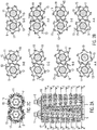
- the FIG. 1 shows a multi-range twin-shaft cutting system 100 according to the present invention.
- the multi-range twin-shaft cutting system 100 according to FIG. 1 shows two separate shafts 1 and 3, which are surrounded by a cylindrical roller body. It is understood that the shape of the roll body around the shaft can also have a different geometric shape, for example, hexagonal or octagonal.
- connection elements / couplings 5 and 7 are shown. In the illustrated arrangement of the cutting system 100 in FIG FIG. 1 the connection element / the coupling 5 for the left shaft 1 and the connection element / the coupling 7 for the right shaft 3 are shown.
- the two shafts 1 and 3 are arranged substantially parallel. The two shafts 1 and 3 are driven in opposite directions. For FIG.
- FIG. 1 shows for the cutting system 100 further support members 9 and 11, which are provided axially to the longitudinal axis of the shaft. It should be the in FIG. 1 shown number of eight support elements 9 or 11 per shaft to be understood as purely exemplary.
- the support elements 9 and 11 are provided spaced apart in the axial direction. In the present example, the distances in the axial direction are substantially uniform.
- the support members 9 and 11 of the shafts are typically formed to have a wavy or rosette-shaped circumferential or circumferential region.
- the undulating peripheral line promotes a better circulation of the material to be shredded and facilitates or optimizes at the same time the collection.
- the optimized circulation and the improved intake can reduce the energy required for shredding.
- the waveform is typically uniform, that is symmetrical about the circumference, and an unbalanced arrangement can be provided to improve the pull-in behavior.
- n The number of maxima of the waveshape of the support elements is denoted by n, for example, where n is a natural number.
- the FIG. 1 further shows cap-like protective elements 27 and 29, which are attached to the support elements 9, 11 of the left shaft 1 and the right shaft 3, respectively.
- the protective elements 27 and 29 are in FIG. 1 by way of example in the region of the smallest distance of the waveform to the center of the support elements 9 and 11 is provided.
- the protective elements 27 and 29 may be plugged or suitably fastened to the support elements 9, 11, as may also be provided instead of the protective elements 27 and 29, another suitable wear protection, such as, for example, build-up welding.
- the width of the distance between two adjacent support elements 9 of the shaft 1 or two adjacent support elements 11 of the shaft 3 is as follows and will be explained from the perspective of the shaft 1, so the left shaft.
- separating elements 17 are provided on the support elements 9 separating elements 17 are provided.
- the partition members 17 are provided so that they can engage in the opposite rotation of the shafts 1 and 3 in the space between two adjacent support members 11 of the other shaft.
- the gap between two adjacent support elements 9 ,.11 is thus at least as wide as the width of the separating elements 17 and 19.
- a separator 17 of the left shaft, in FIG. 1 is provided on the first support member 9 of the shaft 1, in the space between the first and second support member 11, that is, immediately adjacent support members, the right shaft 3 engage.
- the intervention happens during the opposite driving of the waves 1 and 3.
- the support elements 9, 11 of the right and left shaft each have a six-symmetry. This six-symmetry, for example, when looking at the connection elements / couplings 5 and 7 in FIG. 1 clear.
- the six-symmetry is also shown by the number of maximums of the waveform of the peripheral line of the support members 9, 11, as described above.
- the separating elements 17 and 19 are each mounted substantially tangentially on the peripheral region of the support elements 9 and 11. In FIG.
- each of the six separating elements 17, 19 which in FIG. 1 are each mounted on a support member 9, 11, can engage in the corresponding space between two immediately adjacent support members 11, 9 of the respective other shaft.
- each separating element 17, which is mounted on the connection element / from the coupling 5 of the left shaft 1 forth first support member 9, in the space between the first and second support member 11 of the right shaft 3, from the connection element / from the coupling 7 seen, can intervene. It is understood that corresponding correspondences apply to all other support elements 9, 11 and dividing elements 17, 19 of the respective left and right shaft 1, 3.
- n 6
- n 4 or another number.
- the separators of the left shaft are designated by the reference numeral 17.
- the separating elements of the right shaft are designated by the reference numeral 19.
- catch elements for example in the form of knives or fishing hooks are provided, which are designated by the reference numeral 13 are. Accordingly, catch elements are provided on the support elements 11 of the right shaft 3, which are designated by the reference numeral 15. In the axial direction are in FIG. 1 the catch elements 13 and 15 are provided only on some of the support elements 9, 11. It is understood, however, that catch elements 13, 15 can be provided both on some and on all support elements 9, 11. Purely by way of example are in FIG. 1 only on every third support element 9, 11, the catch elements 13, 15 are provided. The catch elements 13 and 15, respectively, improve the intake of material into the multi-shaft cutting system 100.
- the catch elements 13 and 15 can be provided on every second separation element of a support element 9, 11.
- the catch elements 13, 15 separately or it may be provided there a special separator, which results in a combination of catch element and separating element.
- the catch elements 13 and 15 are for example hook-like, knife-like or sickle-shaped, based on the normal direction of rotation.
- the arrangement of some catch elements 13 and 15 against the normal direction of rotation can be provided so that in a blockage of the waves 1 and 3 and required reverse run, the feed material, which has led to the blockage, can be loosened. This should be understood that in the FIG.
- the left shaft 1 in the clockwise direction and the right shaft 3 rotates counterclockwise thereto.
- the material to be crushed is then supplied to the cutting system 100 in accordance with the direction of rotation of the shafts 1, 3 above the two shafts.
- a pull-in or inlet region is thus defined, for example, by an imaginary plane through both longitudinal axes of the two shafts 1, 3.
- the area above this imaginary plane is to be referred to as a catchment area.
- the hook-like, knife-like or sickle-like shape of the catch elements 11, 15 improves the entry into the catchment area.
- an outlet region is provided relative to the direction of rotation of the shafts 1, 3.
- the FIG. 1 further shows counterparts 21 of the left shaft 1 and 23 of the right shaft 3.
- the divisional elements 21 and 23, respectively, also correspond to those in FIG FIG. 1 shown six-symmetry.
- the divisional elements 21, 23 are arranged such that they correspond to the separating elements 17, 19 of the support elements 9, 11 of the respective other shaft.
- the counterparts 21 of the left shaft correspond to the dividers 19 of the right shaft.
- the counterparts 23 of the right shaft correspond to the dividers 17 of the left shaft.
- a separate separating element 21, 23 can therefore be interrupted within the intermediate space in the axial direction. You can also call such a separating element as two or more parts. It is important, however, that the separate separating element 21, 23, in one-part or multi-part form corresponds in each case to the corresponding separating element 17, 19 of the respective other shaft.
- the dividing elements 17 and 19 may be chamfered at their leading edge, ie the edge, which, with respect to the direction of rotation, is substantially first in contact with the material to be comminuted, as in the following Figures 3A-3C shown. Likewise, the front edge of the respective separating elements 17, 19 have an angle against the longitudinal direction of the shaft 1, 3.
- This angle can be between 0 ° and 90 °, preferably between 0 ° and 45 °.
- the support elements 9 respectively 11 of the left and the right shaft 1, 3 are each offset by a few degrees against each other. This arrangement is also clear in the following figures. As a result, the intake and crushing movement of the shaft 1, 3 is further supported.
- FIG. 2 shows in three sub-figures 2A, 2B, 2C views and sections of the cutting system 100 as in FIG. 1 shown.
- FIG. 2A is shown in a plan view of the cutting system 100 with the waves 1 and 3.
- FIG. 2B is exemplified eight sections perpendicular (transverse) to the longitudinal axis of both shafts 1 and 3, which are designated AA, BB, ..., HH, shown individually.
- catch elements / teeth 13 of the left shaft 1 and catch elements 15 of the right shaft 3 are provided on support elements 9 of the left shaft and support elements 11 of the right shaft.
- HH is in each case a shown support member 11 of the right shaft 3 in front of a shown support member 9 of the left shaft.
- a total of 12 catch elements 13 and 15 are shown.
- the Figure 2C shows a view in the longitudinal direction of the shafts 1 and 3 with a view of the connecting elements / couplings 5 and 7. In this case the arrangement of the knife 19 and catch elements 15 of the right shaft 3 and the arrangement of the knife 17 and catch elements 13 of the left shaft 1 is clearly visible.
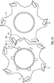
- FIGS. 3A to 3C show the within one revolution solely by the arrangement of the support member 9, 11, the dividing elements 17, 19 and the counterparts 21, 23 resulting correspondences and their respective effects.
- the catch elements 13, 15 have been omitted.
- a support element 9 of the left shaft 1 is behind a support member 11 of the right shaft.
- the outer circumference of the support element 9 of the left shaft 1 engages in the intermediate space between the support element 11 of the right shaft 3 and a support element 11 of the same shaft 3 immediately adjacent thereto.
- the dividing elements 17 and 19 show a beveled, knife-like or cutting-like region 17S or 19S.
- FIG. 3A is a catchment area of the cutting system 100 denoted by I.
- the support members 9 of the left shaft 1 and the support members 11 of the right shaft 3 engage in the opposite driving into each other.
- Two dividers 19R and 17L are designated. From the element 19R is also shown the front beveled portion 19S of the separator. It is understood that the support member 9 engages directly between the support member 11 and a directly behind the support member 11 lying further support member of the right shaft.
- the opposite movement of the two shafts 1, 3 causes the material to be shredded between the separating element 19R of the right shaft 3 and the separating element 17L of the left shaft 1 retracted, cracked and / or broken.
- This comminution thus takes place in the sectional view substantially in the axial direction.
- the wave-shaped circumferential line of the support elements 9, 11 supports this comminution process.
- the left shaft 1 continues to rotate in the clockwise direction and the right shaft 3 counterclockwise. As a result, the left support member 9 and the right support member 11 are also rotated further.
- FIG. 3B is pointed to the area II on the right separating element 19R and the corresponding left counterpart separating element 21. These come so close within the revolution that the material to be shredded is separated and / or cut between the separating element 19R of the right shaft 3 and the separating element 21 of the left shaft 1.
- the counterpart separating element 21 is shown in the shape of an aisle in the form shown here.
- an anvil shape may also be a cutting-like shape be chosen to ensure the separation in a cutting form of the material.
- the correspondence between the separating element 19, 17 and the separate separating element 21, 23 is shown here only by way of example for a separating element 19R of the right shaft 3 and corresponding separating element 21 of the left shaft 1.
- FIG. 3C shows within the same revolution corresponding to the arrangement of the separating elements 19R and 17L, another crushing operation which follows in the sequence of the second and the third crushing operation.
- the separating element 19R is the same separating element as in FIG FIG. 3B shown.
- the separating element 19R of the support element 11 of the right shaft can here work against the rear side of the separating element of the left shaft 17L, so that the material to be comminuted is again comminuted and / or cut. This repeated crushing happens in the outlet area III of the cutting system.
- a very uniform and almost overgrained final product is produced.
- the cutting system 100 may be provided within a crusher (not shown here).
- a crusher may have a funnel-like attachment, funnel, into which the material to be shredded is added.
- This funnel-like attachment may typically be provided above the catchment area of the cutting system 100.
- the fangs 13 and 15 act supportive. It is possible to provide push-pull systems which press the material to be comminuted into the hopper and thus into the comminution unit.
- a system may be provided below the cutting system 100 (not shown), a system may be provided to retain the oversized grain contained in the shredded material and to discharge it accordingly and move it away from the cutting system 100 via a conveyor belt for further use, for example.
- the cutting system 100 can be provided in a mobile, semi-mobile or stationary crusher.
Claims (16)
- Système de coupe multizones à deux arbres (100) pour factionner du matériau, comprenant :deux arbres (1, 3), qui sont agencés sensiblement de manière parallèle l'un à l'autre, et sont entraînés en sens opposé, chaque arbre (1, 3) étant respectivement entouré par un corps de cylindre ;un grand nombre d'éléments de support (9, 11), chaque élément de support (9, 11) étant agencé sensiblement de manière radiale autour du corps de cylindre, et chaque élément de support (9, 11) présentant de préférence une ligne périphérique radialement de forme ondulée, arrondie ou polygonale ou anguleuse ;un grand nombre d'éléments sectionneurs (17, 19), qui sont d'une configuration en forme de disque ou de plaque, et sont placés respectivement de façon sensiblement tangentielle dans la zone périphérique des éléments de support (9, 11) ; systèmedans lequel les éléments de support (9, 11) sont agencés autour des corps de cylindre en étant espacés de manière telle, que chaque élément sectionneur (17, 19) sur un élément de support (9, 11) d'un arbre (1, 3), s'engage entre deux éléments de support (11, 9) directement voisins, de l'autre arbre (3, 1) ; etdans lequel pour chaque arbre (1, 3), respectivement entre deux éléments de support (9, 11) directement voisins de cet arbre (1, 3), sur le corps de cylindre de l'arbre (1, 3) sont placés des éléments sectionneurs conjugués (21, 23), qui sont agencés en correspondance avec les éléments sectionneurs (17, 19) de l'autre arbre (3, 1) de manière telle, que les éléments sectionneurs (17, 19) de l'autre arbre (3, 1), lors de l'engagement réciproque de sens opposé dans l'espace intermédiaire des éléments de support (9, 11) directement voisins, dudit premier arbre (1, 3), travaillent contre les éléments sectionneurs conjugués (21, 23) correspondants, par coupe et/ou broyage, de sorte que le matériau est fractionné ;caractérisé en ce que les éléments sectionneurs (17, 19) d'un premier arbre (1, 3) sont agencés en correspondance avec les éléments sectionneurs (19, 17) de l'autre arbre (3, 1) de manière telle, que lors de l'engagement réciproque de sens opposé des éléments sectionneurs (17, 19) des arbres (1, 3), un élément sectionneur (17, 19) d'un premier arbre (1, 3) travaille par coupe contre un élément sectionneur correspondant (19, 17) de l'autre arbre (1, 3), le bord avant de l'élément sectionneur (17, 19) dudit premier arbre (1, 3) travaillant contre le bord éloigné du bord avant de l'autre élément sectionneur (19, 17) de l'autre arbre (1, 3).
- Système de coupe multizones à deux arbres (100) selon la revendication 1, dans lequel les éléments sectionneurs (17, 19) d'un premier arbre (1, 3) présentent respectivement au moins au niveau de leurs bords avant, en se référant aux éléments sectionneurs conjugués (21, 23) de l'autre arbre (3, 1), une zone de coupe (17S, 19S), qui est par exemple biseautée.
- Système de coupe multizones à deux arbres (100) selon l'une au moins des revendications 1 - 2, dans lequel les éléments sectionneurs (17, 19) de l'arbre (1, 3) sont d'une configuration telle en largeur, que la largeur soit très légèrement inférieure à la distance d'espacement respective entre les deux éléments de support (9, 11) voisins, de sorte que lors de l'engagement réciproque de sens opposé des éléments sectionneurs (17, 19) des arbres (1, 3), dans les éléments de support (9, 11) en regard, un élément sectionneur (17, 19) d'un premier arbre (1, 3) travaille latéralement par broyage et/ou coupe contre deux éléments de support (9, 11) directement voisins, de l'autre arbre (3, 1).
- Système de coupe multizones à deux arbres (100) selon l'une au moins des revendications 1 - 3, dans lequel les éléments sectionneurs (17, 19) respectifs d'un premier arbre (1, 3) sont agencés en correspondance avec les éléments sectionneurs (17, 19) de l'autre arbre (3, 1) de manière telle, que lors de l'engagement réciproque de sens opposé des éléments sectionneurs (17, 19) des arbres (1, 3), un élément sectionneur (17, 19) d'un premier arbre (1, 3) travaille par broyage contre un élément sectionneur (19, 17) directement voisin, de l'autre arbre (3, 1).
- Système de coupe multizones à deux arbres (100) selon l'une au moins des revendications 1 - 4,
dans lequel respectivement les éléments sectionneurs (17, 19) d'un premier arbre (1, 3) sont agencés en correspondance avec les éléments sectionneurs (19, 17) de l'autre arbre (3, 1) et les éléments sectionneurs conjugués (23, 21) de l'autre arbre (3, 1), de manière telle, que pendant un seul tour de sens opposé des deux arbres (1, 3), lors de l'engagement réciproque de sens opposé des éléments sectionneurs (17, 19) des arbres (1, 3), un élément sectionneur (17, 19) dudit premier arbre (1, 3) travaille tout d'abord contre une paire directement voisine des éléments sectionneurs (17, 19) de l'autre arbre (3) ;
dans lequel pendant le même tour des deux arbres (1, 3), lors de l'engagement réciproque de sens opposé des éléments sectionneurs (17, 19) des arbres (1, 3), un élément sectionneur (17, 19) d'un premier arbre (1, 3) travaille tout d'abord latéralement par coupe et/ou par broyage contre une paire directement voisine des éléments de support (9, 1) de l'autre arbre (3, 1), ledit élément sectionneur (17, 19) dudit premier arbre (1, 3) travaille ensuite par coupe contre les éléments sectionneurs conjugués (23, 21) correspondant à cet élément sectionneur (17, 19), de l'autre arbre (3, 1), et ledit élément sectionneur (17, 19) dudit premier arbre (1, 3) travaille ensuite par coupe contre l'élément sectionneur (19, 17) de l'autre arbre (3, 1), qui est placé en correspondance avec cet élément sectionneur (17, 19), contre le bord opposé au bord avant de l'autre élément sectionneur (19, 17). - Système de coupe multizones à deux arbres (100) selon l'une au moins des revendications 1 - 5, dans lequel chaque élément sectionneur (17, 19) d'un premier arbre (1, 3) est respectivement en correspondance avec deux éléments sectionneurs conjugués (23, 21) de deux éléments de support (11, 9) directement voisins, de l'autre arbre (3, 1), les deux éléments sectionneurs conjugués (23, 21) étant espacés dans la direction axiale entre les deux éléments de support (11, 9).
- Système de coupe multizones à deux arbres (100) selon l'une au moins des revendications 1 - 6, dans lequel les éléments sectionneurs conjugués (21, 23) sont prévus directement au niveau des éléments de support (9, 11) sur le corps de cylindre.
- Système de coupe multizones à deux arbres (100) selon l'une au moins des revendications 1 - 7, dans lequel les éléments sectionneurs conjugués (21, 23) sont d'une configuration de forme parallélépipédique ou rectangulaire, et sont prévus, notamment dans la direction axiale, perpendiculairement aux éléments de support (9, 11).
- Système de coupe multizones à deux arbres (100) selon l'une au moins des revendications 1 - 8, dans lequel les éléments sectionneurs conjugués (21, 23) présentent respectivement au niveau de leurs bords avant, qui sont dirigés vers l'autre arbre, une zone de coupe, qui est par exemple biseautée.
- Système de coupe multizones à deux arbres (100) selon l'une au moins des revendications 1 - 9, dans lequel les éléments de support (9, 11) présentent respectivement au niveau de leur distance la plus faible au centre de l'arbre, un élément de protection ou une autre protection anti-usure appropriée (27, 29), ces protections étant respectivement dirigées vers l'autre arbre.
- Système de coupe multizones à deux arbres (100) selon l'une au moins des revendications 1 - 10, dans lequel les bords avant des éléments sectionneurs (17, 19) sont agencés sensiblement dans la direction axiale, parallèlement à l'axe longitudinal de l'arbre (1, 3), ou bien dans lequel les bords avant des éléments sectionneurs (17, 19) sont agencés avec une inclinaison sous un angle α par rapport à l'axe longitudinal de l'arbre (1, 3), l'angle vérifiant la relation suivante : 0° < α < 90°, de préférence 0° < α < 45°.
- Système de coupe multizones à deux arbres (100) selon la revendication 11, dans lequel les éléments sectionneurs conjugués (21, 23) dudit autre arbre (3, 1), en correspondance avec les éléments sectionneurs (17, 19) dudit premier arbre (1, 3), sont agencés conformément à l'inclinaison des éléments sectionneurs (17, 19) correspondants.
- Système de coupe multizones à deux arbres (100) selon l'une au moins des revendications 1 - 12, comprenant par ailleurs un grand nombre d'éléments de saisie (13, 15), qui sont placés sur au moins quelques-uns des éléments de support (9, 11), au niveau de leur périphérie extérieure, sensiblement de manière radiale à l'axe longitudinal de l'arbre (1, 3), les éléments de saisie (13, 15) étant typiquement courbés à la manière de crochets, de manière à être essentiellement dirigés vers l'autre arbre respectif (1, 3).
- Système de coupe multizones à deux arbres (100) selon l'une au moins des revendications 1 - 13, dans lequel les deux arbres (1, 3) sont entraînés de manière synchrone ou asynchrone, et dans lequel chacun des arbres (1, 3) est partiellement interchangeable.
- Système de coupe multizones à deux arbres (100) selon l'une au moins des revendications 1 - 14, dans lequel chacun des deux arbres (1, 3) est entraîné hydrauliquement ou mécaniquement, par l'intermédiaire d'une transmission ou par un entraînement direct.
- Dispositif de fractionnement pour fractionner du matériau, comprenant :un dispositif de trémie pour le remplissage avec le matériau ;un système de coupe multizones à deux arbres (100) selon l'une au moins des revendications 1 - 15 ;un entraînement par moteur, notamment un servomoteur ou un moteur-couple, notamment un moteur électrique ou un moteur Diesel, pour l'entraînement des arbres, et une zone d'évacuation pour l'évacuation et la retenue d'une portion d'une granulométrie supérieure du matériau broyé, la zone d'évacuation étant de préférence réalisée en tant que bande de transport, tiroir, volet ou transporteur à racloirs.
Priority Applications (6)
| Application Number | Priority Date | Filing Date | Title |
|---|---|---|---|
| PL12005918T PL2698207T3 (pl) | 2012-08-16 | 2012-08-16 | Wieloobszarowy dwuwałowy system tnący |
| ES12005918T ES2710622T3 (es) | 2012-08-16 | 2012-08-16 | Sistema de corte de doble árbol de varios niveles |
| EP12005918.3A EP2698207B1 (fr) | 2012-08-16 | 2012-08-16 | Système de coupe à deux arbres à plusieurs niveaux |
| PCT/EP2013/066682 WO2014026916A1 (fr) | 2012-08-16 | 2013-08-09 | Système de découpe à deux arbres comportant plusieurs zones |
| US14/421,937 US10799878B2 (en) | 2012-08-16 | 2013-08-09 | Multi-region twin-shaft cutting system |
| BR112015003405-5A BR112015003405B1 (pt) | 2012-08-16 | 2013-08-09 | sistema de corte de eixo duplo de regiões múltiplas e dispositivo de trituração |
Applications Claiming Priority (1)
| Application Number | Priority Date | Filing Date | Title |
|---|---|---|---|
| EP12005918.3A EP2698207B1 (fr) | 2012-08-16 | 2012-08-16 | Système de coupe à deux arbres à plusieurs niveaux |
Publications (2)
| Publication Number | Publication Date |
|---|---|
| EP2698207A1 EP2698207A1 (fr) | 2014-02-19 |
| EP2698207B1 true EP2698207B1 (fr) | 2018-11-14 |
Family
ID=46799961
Family Applications (1)
| Application Number | Title | Priority Date | Filing Date |
|---|---|---|---|
| EP12005918.3A Active EP2698207B1 (fr) | 2012-08-16 | 2012-08-16 | Système de coupe à deux arbres à plusieurs niveaux |
Country Status (6)
| Country | Link |
|---|---|
| US (1) | US10799878B2 (fr) |
| EP (1) | EP2698207B1 (fr) |
| BR (1) | BR112015003405B1 (fr) |
| ES (1) | ES2710622T3 (fr) |
| PL (1) | PL2698207T3 (fr) |
| WO (1) | WO2014026916A1 (fr) |
Families Citing this family (5)
| Publication number | Priority date | Publication date | Assignee | Title |
|---|---|---|---|---|
| CN105521862B (zh) * | 2016-01-06 | 2018-10-26 | 河北华明木塑制品有限公司 | 一种双齿辊破碎机 |
| EP3248687B1 (fr) | 2016-05-23 | 2019-09-11 | Manuel Lindner | Desintegrateur a deux arbres comprenant un dispositif de changement rapide |
| US11065624B2 (en) * | 2019-07-03 | 2021-07-20 | Scott Equipment Company | Carton reducer/bag opener device |
| CN111346714B (zh) * | 2020-03-16 | 2021-11-26 | 杭州齐协科技有限公司 | 一种自保护的破碎装置 |
| KR102652168B1 (ko) * | 2023-12-12 | 2024-03-29 | 주식회사 아리예스코리아 | 폐기물 파쇄기 |
Family Cites Families (40)
| Publication number | Priority date | Publication date | Assignee | Title |
|---|---|---|---|---|
| US39835A (en) * | 1863-09-08 | Improvement in coal-breaking rolls | ||
| US1435330A (en) * | 1921-12-30 | 1922-11-14 | Pardee Frank | Coal breaker |
| US2472188A (en) * | 1946-02-07 | 1949-06-07 | Gifford Wood Co | Ice breaker |
| US3027106A (en) * | 1959-02-19 | 1962-03-27 | Hoe & Co R | Rotary saw break-up head |
| US3261384A (en) * | 1965-05-19 | 1966-07-19 | George A Henderson | Circular saw |
| JPS5376465A (en) * | 1976-12-17 | 1978-07-06 | Kobe Steel Ltd | Crusher |
| JPS54178287U (fr) | 1978-06-07 | 1979-12-17 | ||
| US4765217A (en) * | 1985-08-30 | 1988-08-23 | Ludwig Andre M | Insertable saw tooth |
| DE3711228A1 (de) * | 1987-04-03 | 1988-10-20 | Wagner Maschf Gustav | Schneidezahn sowie mit solchen schneidezaehnen versehene metallsaegen, insbesondere kreissaegeblaetter |
| US5048764A (en) * | 1989-11-06 | 1991-09-17 | Flament Gregory J | Apparatus for comminuting solid waste |
| DE9110457U1 (fr) | 1991-08-23 | 1991-12-19 | Hammel, Norbert, 6301 Reiskirchen, De | |
| US6092753A (en) * | 1993-06-01 | 2000-07-25 | Koenig; Larry E. | Material processing apparatus |
| US5481952A (en) * | 1994-01-27 | 1996-01-09 | Maclennan; Charles D. | Slasher saw blade assembly |
| US5511729A (en) * | 1994-08-15 | 1996-04-30 | Yeomans Chicago Corporation | Waste comminutor and cutter elements therefor |
| DE9415955U1 (de) * | 1994-10-04 | 1994-11-24 | Mock Gerhard Dipl Ing | Zerkleinerungsvorrichtung |
| US5676321A (en) * | 1995-04-03 | 1997-10-14 | Fellowes Mfg. Co. | Cutting disk |
| US5904305A (en) * | 1997-05-14 | 1999-05-18 | Kaczmarek; Win F. | Rubber reducing and recycling system |
| US6357680B1 (en) * | 1999-06-16 | 2002-03-19 | Jere F. Irwin | Self-feeding comminuting apparatus having improved drive motor features |
| US6644570B1 (en) * | 1999-10-15 | 2003-11-11 | Jere F. Irwin | Downstream pneumatic recirculation comminuting apparatus |
| US6513740B2 (en) * | 2001-01-24 | 2003-02-04 | Ming-Hui Ho | Blade of a paper shredder |
| AUPR274701A0 (en) * | 2001-01-29 | 2001-02-22 | Parke, Terrence James | Self-cleaning shredding device having movable cleaning rings |
| EP1334771B1 (fr) * | 2002-02-06 | 2016-12-07 | Hermann Schwelling | Destructeur de documents |
| CN2636985Y (zh) * | 2003-06-30 | 2004-09-01 | 罗贤俐 | 多刃型的碎纸机刀具 |
| EP1699561A1 (fr) * | 2003-11-08 | 2006-09-13 | MMD DESIGN & CONSULTANCY LIMITED | Structure de tambour pour broyeur de mineraux |
| US7644881B2 (en) * | 2003-11-26 | 2010-01-12 | Michilin Prosperity Co., Ltd. | Round undulating blade, blade module, and rotary assembly for shredder |
| US7533839B2 (en) * | 2006-11-20 | 2009-05-19 | Michilin Prosperity Co., Ltd | Cutting blade and rotary cutting assembly for shredders |
| US20050263633A1 (en) * | 2004-05-25 | 2005-12-01 | Vantrease Dale L | Serrated scissor ring, comminuting apparatus, and method |
| CN2751888Y (zh) * | 2004-11-17 | 2006-01-18 | 白淑惠 | 碎纸机刀片 |
| DE102005026816B4 (de) | 2005-06-09 | 2007-09-27 | Vecoplan Maschinenfabrik Gmbh & Co. Kg | Zerkleinerungsvorrichtung |
| CN2838753Y (zh) * | 2005-09-20 | 2006-11-22 | 牛玉文 | 碎纸机的刀片 |
| US20070181721A1 (en) * | 2005-11-09 | 2007-08-09 | Ko Joseph Y | Devices and methods for shredding media into different sizes |
| CN2877858Y (zh) * | 2005-12-02 | 2007-03-14 | 上海震旦办公设备有限公司 | 碎纸机刀具结构 |
| CN2877859Y (zh) * | 2006-01-05 | 2007-03-14 | 上海震旦办公设备有限公司 | 碎纸机的圆形刀片及刀片模块 |
| US7641135B1 (en) * | 2006-02-28 | 2010-01-05 | Emily Lo | Combinative cutting wheel of a rotary cutter of paper shredder |
| US7328867B1 (en) * | 2006-02-28 | 2008-02-12 | Emily Lo | Blade for a paper shredder cutting tool |
| DE202007007982U1 (de) | 2006-11-29 | 2007-10-11 | Bauernfeind, André | Zerkleinerungsvorrichtung |
| USD594040S1 (en) * | 2007-03-21 | 2009-06-09 | Steven N Cadwallader | Turbo pump dispersion blade |
| DE102009038984B4 (de) | 2009-08-20 | 2013-07-11 | HAAS Holzzerkleinerungs- und Fördertechnik GmbH | Vorrichtung zum Zerkleinern von Stückgut |
| JP2011230117A (ja) * | 2010-04-06 | 2011-11-17 | Kokuyo Co Ltd | シュレッダ用ローラーカッター及びシュレッダ |
| US8418947B2 (en) * | 2011-02-24 | 2013-04-16 | Stephen Kwok Ki Chan | Shredding mechanism for paper |
-
2012
- 2012-08-16 EP EP12005918.3A patent/EP2698207B1/fr active Active
- 2012-08-16 ES ES12005918T patent/ES2710622T3/es active Active
- 2012-08-16 PL PL12005918T patent/PL2698207T3/pl unknown
-
2013
- 2013-08-09 WO PCT/EP2013/066682 patent/WO2014026916A1/fr active Application Filing
- 2013-08-09 BR BR112015003405-5A patent/BR112015003405B1/pt active IP Right Grant
- 2013-08-09 US US14/421,937 patent/US10799878B2/en active Active
Non-Patent Citations (1)
| Title |
|---|
| None * |
Also Published As
| Publication number | Publication date |
|---|---|
| US20190151856A1 (en) | 2019-05-23 |
| US10799878B2 (en) | 2020-10-13 |
| WO2014026916A1 (fr) | 2014-02-20 |
| PL2698207T3 (pl) | 2019-05-31 |
| BR112015003405B1 (pt) | 2021-05-25 |
| ES2710622T3 (es) | 2019-04-26 |
| EP2698207A1 (fr) | 2014-02-19 |
| BR112015003405A2 (pt) | 2017-07-04 |
Similar Documents
| Publication | Publication Date | Title |
|---|---|---|
| DE102005026816B4 (de) | Zerkleinerungsvorrichtung | |
| EP2698207B1 (fr) | Système de coupe à deux arbres à plusieurs niveaux | |
| EP2679309B1 (fr) | Dispositif de broyage comprenant un rotor de broyage avec lame traversante | |
| EP2711081A1 (fr) | Dispositif de broyage | |
| CH616604A5 (fr) | ||
| EP2065092B1 (fr) | Dispositif et procédé destinés à dissoudre le composite à partir de matériaux de chargement se trouvant dans le composite | |
| EP1497032B1 (fr) | Dispositif de broyage | |
| EP2537588B1 (fr) | Déchiqueteur avec lames à plusieurs tranchants | |
| CH659405A5 (de) | Zerkleinerungsvorrichtung fuer abfall. | |
| DE102005039200B4 (de) | Zerkleinerungsvorrichtung mit mehreren, im Wesentlichen parallel verlaufenden, motorisch angetriebenen, rotierenden oder oszillierenden Wellen | |
| EP0022537B1 (fr) | Machine pour le broyage d'objets encombrants | |
| EP2454019A2 (fr) | Couteau pour machine de fragmentation et utilisation d'un tel couteau dans une machine de fragmentation | |
| DE112015004361T5 (de) | Perforierter Rotationsschneider | |
| DE3910115C2 (fr) | ||
| EP0486872B1 (fr) | Déchiqueteur rotatif pour le broyage de déchets | |
| DE202012007852U1 (de) | Mehrbereichs-Zweiwellen-Schneidsystem | |
| DE102009038984A1 (de) | Vorrichtung zum Zerkleinern von Stückgut | |
| DE10113953C1 (de) | Vorrichtung zum Zerkleinern von Kunststoffgebilden mit geringer Materialstärke | |
| EP2549892B1 (fr) | Porte-couteaux pour dispositif de désintégration de matière organique | |
| DE7818838U1 (de) | Maschine zum zerkleinern von abfallstoffen | |
| DE10048886C2 (de) | Vorrichtung zum Zerkleinern von Aufgabegut mit einem um eine Drehachse rotierenden Zerkleinerungssystem | |
| DE10234763A1 (de) | Verfahren und Vorrichtung zum Zerkleinern von Schüttgut | |
| AT406354B (de) | Zerkleinerungsvorrichtung | |
| DE2827544A1 (de) | Zerkleinerungsanlage | |
| WO2014173384A1 (fr) | Dispositif pour broyer des résidus en morceaux provenant de l'extraction de l'huile de palme |
Legal Events
| Date | Code | Title | Description |
|---|---|---|---|
| AK | Designated contracting states |
Kind code of ref document: A1 Designated state(s): AL AT BE BG CH CY CZ DE DK EE ES FI FR GB GR HR HU IE IS IT LI LT LU LV MC MK MT NL NO PL PT RO RS SE SI SK SM TR |
|
| AX | Request for extension of the european patent |
Extension state: BA ME |
|
| PUAI | Public reference made under article 153(3) epc to a published international application that has entered the european phase |
Free format text: ORIGINAL CODE: 0009012 |
|
| 17P | Request for examination filed |
Effective date: 20140819 |
|
| RBV | Designated contracting states (corrected) |
Designated state(s): AL AT BE BG CH CY CZ DE DK EE ES FI FR GB GR HR HU IE IS IT LI LT LU LV MC MK MT NL NO PL PT RO RS SE SI SK SM TR |
|
| STAA | Information on the status of an ep patent application or granted ep patent |
Free format text: STATUS: EXAMINATION IS IN PROGRESS |
|
| 17Q | First examination report despatched |
Effective date: 20171206 |
|
| GRAP | Despatch of communication of intention to grant a patent |
Free format text: ORIGINAL CODE: EPIDOSNIGR1 |
|
| STAA | Information on the status of an ep patent application or granted ep patent |
Free format text: STATUS: GRANT OF PATENT IS INTENDED |
|
| INTG | Intention to grant announced |
Effective date: 20180612 |
|
| RAP1 | Party data changed (applicant data changed or rights of an application transferred) |
Owner name: LINDNER-RECYCLINGTECH GMBH |
|
| RAP1 | Party data changed (applicant data changed or rights of an application transferred) |
Owner name: LINDNER-RECYCLINGTECH GMBH |
|
| GRAS | Grant fee paid |
Free format text: ORIGINAL CODE: EPIDOSNIGR3 |
|
| GRAA | (expected) grant |
Free format text: ORIGINAL CODE: 0009210 |
|
| STAA | Information on the status of an ep patent application or granted ep patent |
Free format text: STATUS: THE PATENT HAS BEEN GRANTED |
|
| AK | Designated contracting states |
Kind code of ref document: B1 Designated state(s): AL AT BE BG CH CY CZ DE DK EE ES FI FR GB GR HR HU IE IS IT LI LT LU LV MC MK MT NL NO PL PT RO RS SE SI SK SM TR |
|
| REG | Reference to a national code |
Ref country code: GB Ref legal event code: FG4D Free format text: NOT ENGLISH |
|
| REG | Reference to a national code |
Ref country code: CH Ref legal event code: EP Ref country code: AT Ref legal event code: REF Ref document number: 1064190 Country of ref document: AT Kind code of ref document: T Effective date: 20181115 |
|
| REG | Reference to a national code |
Ref country code: DE Ref legal event code: R096 Ref document number: 502012013800 Country of ref document: DE |
|
| REG | Reference to a national code |
Ref country code: IE Ref legal event code: FG4D Free format text: LANGUAGE OF EP DOCUMENT: GERMAN |
|
| REG | Reference to a national code |
Ref country code: CH Ref legal event code: NV Representative=s name: BOVARD AG PATENT- UND MARKENANWAELTE, CH |
|
| REG | Reference to a national code |
Ref country code: NL Ref legal event code: MP Effective date: 20181114 |
|
| REG | Reference to a national code |
Ref country code: LT Ref legal event code: MG4D |
|
| REG | Reference to a national code |
Ref country code: ES Ref legal event code: FG2A Ref document number: 2710622 Country of ref document: ES Kind code of ref document: T3 Effective date: 20190426 |
|
| PG25 | Lapsed in a contracting state [announced via postgrant information from national office to epo] |
Ref country code: LV Free format text: LAPSE BECAUSE OF FAILURE TO SUBMIT A TRANSLATION OF THE DESCRIPTION OR TO PAY THE FEE WITHIN THE PRESCRIBED TIME-LIMIT Effective date: 20181114 Ref country code: HR Free format text: LAPSE BECAUSE OF FAILURE TO SUBMIT A TRANSLATION OF THE DESCRIPTION OR TO PAY THE FEE WITHIN THE PRESCRIBED TIME-LIMIT Effective date: 20181114 Ref country code: BG Free format text: LAPSE BECAUSE OF FAILURE TO SUBMIT A TRANSLATION OF THE DESCRIPTION OR TO PAY THE FEE WITHIN THE PRESCRIBED TIME-LIMIT Effective date: 20190214 Ref country code: LT Free format text: LAPSE BECAUSE OF FAILURE TO SUBMIT A TRANSLATION OF THE DESCRIPTION OR TO PAY THE FEE WITHIN THE PRESCRIBED TIME-LIMIT Effective date: 20181114 Ref country code: IS Free format text: LAPSE BECAUSE OF FAILURE TO SUBMIT A TRANSLATION OF THE DESCRIPTION OR TO PAY THE FEE WITHIN THE PRESCRIBED TIME-LIMIT Effective date: 20190314 Ref country code: NO Free format text: LAPSE BECAUSE OF FAILURE TO SUBMIT A TRANSLATION OF THE DESCRIPTION OR TO PAY THE FEE WITHIN THE PRESCRIBED TIME-LIMIT Effective date: 20190214 |
|
| PG25 | Lapsed in a contracting state [announced via postgrant information from national office to epo] |
Ref country code: GR Free format text: LAPSE BECAUSE OF FAILURE TO SUBMIT A TRANSLATION OF THE DESCRIPTION OR TO PAY THE FEE WITHIN THE PRESCRIBED TIME-LIMIT Effective date: 20190215 Ref country code: RS Free format text: LAPSE BECAUSE OF FAILURE TO SUBMIT A TRANSLATION OF THE DESCRIPTION OR TO PAY THE FEE WITHIN THE PRESCRIBED TIME-LIMIT Effective date: 20181114 Ref country code: SE Free format text: LAPSE BECAUSE OF FAILURE TO SUBMIT A TRANSLATION OF THE DESCRIPTION OR TO PAY THE FEE WITHIN THE PRESCRIBED TIME-LIMIT Effective date: 20181114 Ref country code: AL Free format text: LAPSE BECAUSE OF FAILURE TO SUBMIT A TRANSLATION OF THE DESCRIPTION OR TO PAY THE FEE WITHIN THE PRESCRIBED TIME-LIMIT Effective date: 20181114 Ref country code: NL Free format text: LAPSE BECAUSE OF FAILURE TO SUBMIT A TRANSLATION OF THE DESCRIPTION OR TO PAY THE FEE WITHIN THE PRESCRIBED TIME-LIMIT Effective date: 20181114 Ref country code: PT Free format text: LAPSE BECAUSE OF FAILURE TO SUBMIT A TRANSLATION OF THE DESCRIPTION OR TO PAY THE FEE WITHIN THE PRESCRIBED TIME-LIMIT Effective date: 20190314 |
|
| PG25 | Lapsed in a contracting state [announced via postgrant information from national office to epo] |
Ref country code: DK Free format text: LAPSE BECAUSE OF FAILURE TO SUBMIT A TRANSLATION OF THE DESCRIPTION OR TO PAY THE FEE WITHIN THE PRESCRIBED TIME-LIMIT Effective date: 20181114 Ref country code: CZ Free format text: LAPSE BECAUSE OF FAILURE TO SUBMIT A TRANSLATION OF THE DESCRIPTION OR TO PAY THE FEE WITHIN THE PRESCRIBED TIME-LIMIT Effective date: 20181114 |
|
| REG | Reference to a national code |
Ref country code: DE Ref legal event code: R097 Ref document number: 502012013800 Country of ref document: DE |
|
| PG25 | Lapsed in a contracting state [announced via postgrant information from national office to epo] |
Ref country code: RO Free format text: LAPSE BECAUSE OF FAILURE TO SUBMIT A TRANSLATION OF THE DESCRIPTION OR TO PAY THE FEE WITHIN THE PRESCRIBED TIME-LIMIT Effective date: 20181114 Ref country code: SM Free format text: LAPSE BECAUSE OF FAILURE TO SUBMIT A TRANSLATION OF THE DESCRIPTION OR TO PAY THE FEE WITHIN THE PRESCRIBED TIME-LIMIT Effective date: 20181114 Ref country code: EE Free format text: LAPSE BECAUSE OF FAILURE TO SUBMIT A TRANSLATION OF THE DESCRIPTION OR TO PAY THE FEE WITHIN THE PRESCRIBED TIME-LIMIT Effective date: 20181114 Ref country code: SK Free format text: LAPSE BECAUSE OF FAILURE TO SUBMIT A TRANSLATION OF THE DESCRIPTION OR TO PAY THE FEE WITHIN THE PRESCRIBED TIME-LIMIT Effective date: 20181114 |
|
| PLBE | No opposition filed within time limit |
Free format text: ORIGINAL CODE: 0009261 |
|
| STAA | Information on the status of an ep patent application or granted ep patent |
Free format text: STATUS: NO OPPOSITION FILED WITHIN TIME LIMIT |
|
| 26N | No opposition filed |
Effective date: 20190815 |
|
| PG25 | Lapsed in a contracting state [announced via postgrant information from national office to epo] |
Ref country code: SI Free format text: LAPSE BECAUSE OF FAILURE TO SUBMIT A TRANSLATION OF THE DESCRIPTION OR TO PAY THE FEE WITHIN THE PRESCRIBED TIME-LIMIT Effective date: 20181114 |
|
| PG25 | Lapsed in a contracting state [announced via postgrant information from national office to epo] |
Ref country code: TR Free format text: LAPSE BECAUSE OF FAILURE TO SUBMIT A TRANSLATION OF THE DESCRIPTION OR TO PAY THE FEE WITHIN THE PRESCRIBED TIME-LIMIT Effective date: 20181114 |
|
| PG25 | Lapsed in a contracting state [announced via postgrant information from national office to epo] |
Ref country code: MC Free format text: LAPSE BECAUSE OF FAILURE TO SUBMIT A TRANSLATION OF THE DESCRIPTION OR TO PAY THE FEE WITHIN THE PRESCRIBED TIME-LIMIT Effective date: 20181114 Ref country code: LU Free format text: LAPSE BECAUSE OF NON-PAYMENT OF DUE FEES Effective date: 20190816 |
|
| REG | Reference to a national code |
Ref country code: BE Ref legal event code: MM Effective date: 20190831 |
|
| PG25 | Lapsed in a contracting state [announced via postgrant information from national office to epo] |
Ref country code: BE Free format text: LAPSE BECAUSE OF NON-PAYMENT OF DUE FEES Effective date: 20190831 |
|
| REG | Reference to a national code |
Ref country code: AT Ref legal event code: MM01 Ref document number: 1064190 Country of ref document: AT Kind code of ref document: T Effective date: 20190816 |
|
| PG25 | Lapsed in a contracting state [announced via postgrant information from national office to epo] |
Ref country code: AT Free format text: LAPSE BECAUSE OF NON-PAYMENT OF DUE FEES Effective date: 20190816 |
|
| PG25 | Lapsed in a contracting state [announced via postgrant information from national office to epo] |
Ref country code: CY Free format text: LAPSE BECAUSE OF FAILURE TO SUBMIT A TRANSLATION OF THE DESCRIPTION OR TO PAY THE FEE WITHIN THE PRESCRIBED TIME-LIMIT Effective date: 20181114 |
|
| PG25 | Lapsed in a contracting state [announced via postgrant information from national office to epo] |
Ref country code: HU Free format text: LAPSE BECAUSE OF FAILURE TO SUBMIT A TRANSLATION OF THE DESCRIPTION OR TO PAY THE FEE WITHIN THE PRESCRIBED TIME-LIMIT; INVALID AB INITIO Effective date: 20120816 Ref country code: MT Free format text: LAPSE BECAUSE OF FAILURE TO SUBMIT A TRANSLATION OF THE DESCRIPTION OR TO PAY THE FEE WITHIN THE PRESCRIBED TIME-LIMIT Effective date: 20181114 |
|
| PG25 | Lapsed in a contracting state [announced via postgrant information from national office to epo] |
Ref country code: MK Free format text: LAPSE BECAUSE OF FAILURE TO SUBMIT A TRANSLATION OF THE DESCRIPTION OR TO PAY THE FEE WITHIN THE PRESCRIBED TIME-LIMIT Effective date: 20181114 |
|
| PGFP | Annual fee paid to national office [announced via postgrant information from national office to epo] |
Ref country code: IT Payment date: 20230829 Year of fee payment: 12 Ref country code: IE Payment date: 20230823 Year of fee payment: 12 Ref country code: GB Payment date: 20230824 Year of fee payment: 12 Ref country code: FI Payment date: 20230824 Year of fee payment: 12 Ref country code: ES Payment date: 20230901 Year of fee payment: 12 Ref country code: CH Payment date: 20230902 Year of fee payment: 12 |
|
| PGFP | Annual fee paid to national office [announced via postgrant information from national office to epo] |
Ref country code: PL Payment date: 20230731 Year of fee payment: 12 Ref country code: FR Payment date: 20230824 Year of fee payment: 12 Ref country code: DE Payment date: 20230830 Year of fee payment: 12 |