EP2696731B1 - System und verfahren zur abgabe abgemessener mengen eines losen materials - Google Patents
System und verfahren zur abgabe abgemessener mengen eines losen materials Download PDFInfo
- Publication number
- EP2696731B1 EP2696731B1 EP12771314.7A EP12771314A EP2696731B1 EP 2696731 B1 EP2696731 B1 EP 2696731B1 EP 12771314 A EP12771314 A EP 12771314A EP 2696731 B1 EP2696731 B1 EP 2696731B1
- Authority
- EP
- European Patent Office
- Prior art keywords
- tea
- dispenser
- electronic controller
- housing
- user interface
- Prior art date
- Legal status (The legal status is an assumption and is not a legal conclusion. Google has not performed a legal analysis and makes no representation as to the accuracy of the status listed.)
- Active
Links
- 239000000463 material Substances 0.000 title claims description 56
- 238000000034 method Methods 0.000 title claims description 11
- 241001122767 Theaceae Species 0.000 claims description 132
- 230000007246 mechanism Effects 0.000 claims description 12
- 230000004913 activation Effects 0.000 claims description 6
- 239000013590 bulk material Substances 0.000 claims 13
- 239000012530 fluid Substances 0.000 claims 3
- 238000007789 sealing Methods 0.000 claims 3
- 230000003213 activating effect Effects 0.000 claims 1
- 235000013616 tea Nutrition 0.000 description 119
- 235000013361 beverage Nutrition 0.000 description 12
- 238000005259 measurement Methods 0.000 description 8
- 230000008569 process Effects 0.000 description 7
- 238000003860 storage Methods 0.000 description 7
- 238000004519 manufacturing process Methods 0.000 description 6
- 235000016213 coffee Nutrition 0.000 description 4
- 235000013353 coffee beverage Nutrition 0.000 description 4
- 239000000843 powder Substances 0.000 description 3
- XLYOFNOQVPJJNP-UHFFFAOYSA-N water Substances O XLYOFNOQVPJJNP-UHFFFAOYSA-N 0.000 description 3
- 230000009286 beneficial effect Effects 0.000 description 2
- 230000000903 blocking effect Effects 0.000 description 2
- 235000013305 food Nutrition 0.000 description 2
- 230000005484 gravity Effects 0.000 description 2
- 239000002184 metal Substances 0.000 description 2
- 235000013324 preserved food Nutrition 0.000 description 2
- 235000013599 spices Nutrition 0.000 description 2
- 238000005303 weighing Methods 0.000 description 2
- 230000004075 alteration Effects 0.000 description 1
- 238000013459 approach Methods 0.000 description 1
- 239000003990 capacitor Substances 0.000 description 1
- 235000020329 chai tea Nutrition 0.000 description 1
- 230000003247 decreasing effect Effects 0.000 description 1
- 239000003599 detergent Substances 0.000 description 1
- 230000000694 effects Effects 0.000 description 1
- 230000006870 function Effects 0.000 description 1
- 239000004615 ingredient Substances 0.000 description 1
- 235000020166 milkshake Nutrition 0.000 description 1
- 238000012986 modification Methods 0.000 description 1
- 230000004048 modification Effects 0.000 description 1
- 238000004806 packaging method and process Methods 0.000 description 1
- 230000037361 pathway Effects 0.000 description 1
- 230000001737 promoting effect Effects 0.000 description 1
- 230000009467 reduction Effects 0.000 description 1
- 238000004904 shortening Methods 0.000 description 1
- 235000013570 smoothie Nutrition 0.000 description 1
- 239000002699 waste material Substances 0.000 description 1
Images


Classifications
-
- A—HUMAN NECESSITIES
- A47—FURNITURE; DOMESTIC ARTICLES OR APPLIANCES; COFFEE MILLS; SPICE MILLS; SUCTION CLEANERS IN GENERAL
- A47J—KITCHEN EQUIPMENT; COFFEE MILLS; SPICE MILLS; APPARATUS FOR MAKING BEVERAGES
- A47J31/00—Apparatus for making beverages
- A47J31/40—Beverage-making apparatus with dispensing means for adding a measured quantity of ingredients, e.g. coffee, water, sugar, cocoa, milk, tea
- A47J31/404—Powder dosing devices
-
- B—PERFORMING OPERATIONS; TRANSPORTING
- B65—CONVEYING; PACKING; STORING; HANDLING THIN OR FILAMENTARY MATERIAL
- B65G—TRANSPORT OR STORAGE DEVICES, e.g. CONVEYORS FOR LOADING OR TIPPING, SHOP CONVEYOR SYSTEMS OR PNEUMATIC TUBE CONVEYORS
- B65G15/00—Conveyors having endless load-conveying surfaces, i.e. belts and like continuous members, to which tractive effort is transmitted by means other than endless driving elements of similar configuration
-
- B—PERFORMING OPERATIONS; TRANSPORTING
- B65—CONVEYING; PACKING; STORING; HANDLING THIN OR FILAMENTARY MATERIAL
- B65G—TRANSPORT OR STORAGE DEVICES, e.g. CONVEYORS FOR LOADING OR TIPPING, SHOP CONVEYOR SYSTEMS OR PNEUMATIC TUBE CONVEYORS
- B65G33/00—Screw or rotary spiral conveyors
- B65G33/08—Screw or rotary spiral conveyors for fluent solid materials
- B65G33/14—Screw or rotary spiral conveyors for fluent solid materials comprising a screw or screws enclosed in a tubular housing
- B65G33/16—Screw or rotary spiral conveyors for fluent solid materials comprising a screw or screws enclosed in a tubular housing with flexible screws operating in flexible tubes
-
- B—PERFORMING OPERATIONS; TRANSPORTING
- B65—CONVEYING; PACKING; STORING; HANDLING THIN OR FILAMENTARY MATERIAL
- B65G—TRANSPORT OR STORAGE DEVICES, e.g. CONVEYORS FOR LOADING OR TIPPING, SHOP CONVEYOR SYSTEMS OR PNEUMATIC TUBE CONVEYORS
- B65G33/00—Screw or rotary spiral conveyors
- B65G33/24—Details
- B65G33/26—Screws
-
- G—PHYSICS
- G01—MEASURING; TESTING
- G01G—WEIGHING
- G01G15/00—Arrangements for check-weighing of materials dispensed into removable containers
Definitions
- aspects of the present disclosure relate to a container and dispenser for storing and dispensing loose materials, such as coffee, tea, powder, or other like materials.
- the tea bag was developed, which contains a pre-determined amount of tea and is used to create a common sized beverage, such as 8 ounces.
- tea bags are a lesser preferred option to fresh tea, as the tea spends quite some time in storage and transit prior to being delivered for use.
- tea bags do not lend themselves easily to the production of teas of varying quantities, such as 8 ounces, 12 ounces, or a full tea pot.
- "pods" or "cups” were developed which are used in automated machines; however, these pods suffer from the same problems as using tea bags. Accordingly, the present invention solves a number of these problems as well as other problems present in the dispensing industry, as are illustrated in the descriptions that follow.
- EP 0640311 describes a device for packaging, transporting and dispensing controlled doses of granular or powdery goods, such as a food product.
- a changeable container and a portioning device can be connected to each other.
- the portioning device has electric control means for the dosed dispensing of goods. Both the changeable container and the portioning device can be used as often as is desired.
- US 4,723,614 describes a modular apparatus for dispensing weight-controlled foodstuff portions.
- the apparatus includes a housing which supports a removable silo, feeder screw and blocking plate components which discharge the foodstuff to a dosage cup.
- a capacitor transducer is employed to support the dosage cup and perform a weighing function.
- the housing has an opening for receiving foodstuff from the silo which leads to a feeder pathway.
- the removeable feeder screw advances the food to the blocking plate which through a vibrator motion effects discharge to the dosage cup.
- An electronic control card inputs a weighing signal from the transducer for controlled operation of the apparatus.
- the present invention involves various aspects of a container and/or dispenser for use in dispensing loose materials, such as dry products.
- Suitable dry products for use with the novel dispenser disclosed herein include tea, spices, coffee, dried foods, other powders and the like.
- the container and dispenser described herein shall be described with respect to the dispensing of loose leaf tea. However, it shall be appreciated that the system could be easily applied to other loose materials, such as, but not limited to, those listed above.
- the dispenser may include a coin/bill acceptor and/or credit card terminal or like device for use as a vending machine.
- An illustrative embodiment of the present invention is a loose leaf tea system including a container and dispenser.
- the tea container serves to store the tea leaves or grounds in a storage bin prior to activation of the system.
- the dispenser measures and loads a selected amount of tea into a hopper for dispensing, such as into a waiting cup, tea pot, or a tea infuser.
- the amount of tea may be selected based upon user operation of one of a number of quantity indicating/selection buttons provided in a user interface or may be otherwise input by the user, such as by rotating a dial or pushing a button or lever.
- the container is preferably a sealed canister, such as a bag or jug, which may be stored within the dispenser so as to not expose the material contained to light, air and/or moisture.
- no external canister is used, rather the container is a sealed refillable housing formed within the device, so as to prevent additional waste and increase efficiency.
- a mechanism is provided below the opening in the container or housing below.
- the mechanism preferably seals when not in use so as to prevent the tea in the container from coming into contact with the outside atmosphere prior to entering the hopper below.
- the dispenser is able to operate the mechanism such that it loads a desired amount of tea (e.g. by weight), specified by the user, into the hopper. Once the desired amount of tea is loaded into the hopper, the tea may be dispensed into a desired location, such as into a waiting cup, tea pot, or infuser below.
- a container and/or dispenser for use in dispensing loose materials such as dry products
- Suitable dry products for use with the novel dispenser disclosed herein include tea, spices, coffee, dried foods, laundry detergent, other powders and the like.
- the container and dispenser described herein shall be described with respect to the dispensing of loose leaf tea.
- the container and dispenser could be easily applied to other loose materials, such as, but not limited to, those listed above.
- the dispenser may include a coin/bill acceptor and/or credit card terminal or like device for use as a vending machine.
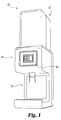
- Tea dispenser 20 is illustrated in a stand alone form having an upper portion 22 for storing tea, a middle portion 24 for dispensing and measuring tea, and a bottom portion 26 providing a location for the user to place a receptacle, such as a cup, kettle, tea pot, infuser, or the like for receiving the dispensed tea.
- tea dispenser 20 includes an electronic controller 80 which includes a user interface and controls the operation of the remaining portions of tea dispenser 20. It shall be appreciated that tea dispenser 20 may take various other forms and configurations depending upon user needs and requirements.
- tea dispenser 20 is shown absent its middle portion 24 and bottom portion 26 and its external housing for purposes of illustrating the internal components of upper portion 22.
- tea dispenser 20 includes an interchangeable tea container 30 for attachment to a receiving portion 40.
- tea dispenser 20 includes measuring portion 50.
- receiving portion 40 may include an lid, which preferably establishes an airtight seal, so that receiving portion 40 may serve the purposes of container 30 without the need for a separate container 30.
- tea storage bin 31 is a hollow recess suitable for the storage of tea for subsequent dispensing formed by receiving portion 40.
- storage bin 31 also comprises a standard lid 33 which preferably forms an air tight hermetic seal with respect to storage bin 31 to prevent the contents of storage bin 31 from coming into contact with the outside environment, thereby maintaining its freshness prior to dispensing.
- Measuring portion 50 mounts to the base of receiving portion 40 and serves to controllably release the contents of container 30, using the force of gravity.
- the dispensing is controlled by dispenser chute 52, which includes helical coil or screw 56, motor 57, and seal 155, all of which are described further herein with respect to FIGs. 6 , 8 and 9 .
- FIGs. 4 and 5 show exemplary plan views of two user interfaces suitable for use on tea dispenser 20. It shall be appreciated that many user interface designs may be utilized without departing from the scope of the present disclosure.
- FIG. 4 illustrates a touch screen user interface 81 in which a number of user selectable options are provided for various sized beverages.
- user interface 81 may include logical buttons 82, 83, and 84 which correspond to an 8 oz., 16 oz, and 20 oz. beverage respectively. Additionally, one or more of these buttons may be programmed to provide a customized size, such as 12, 18, or 20 ozs.
- buttons associated with these buttons may be customized by the user so as to correspond to the sizes of tea which the user prefers or which are available on the menu, such as in the case of a restaurant or tea shop. Additionally, when the user interface is provided in a touch screen, the buttons may be changed so as to show to currently programmed size, such as in ounces (or the metric equivalent), or the like. Furthermore, if desired, one or more buttons may be customized to provide for a larger volume, such as that of a tea pot.
- internal controller 80 (shown in FIG. 1 ) is configured to operate tea dispenser 20 to dispense a measured amount of tea suitable for providing an 8 oz. tea beverage.
- the user interface may remain relatively simply, if desired.
- the weights corresponding to the various buttons may be increased accordingly depending upon the type of tea the device is currently configured for.
- user interface 81 may accept input regarding one of a number of predefined types of teas and a desired volume of tea. Based upon the currently selected tea, the amount of tea dispensed (such as by weight) for the selected volume may be different than it would have been had a different tea type been selected.
- FIG. 5 an alternate, more user adjustable user interface 85 is illustrated in which a number of user selectable options are provided for various sized beverages in addition to a strength adjustment.
- user interface 85 may include display 86 and buttons 87, 88, and 89 which correspond to an 8 oz., 16 oz, and 20 oz. beverage or other like amounts.
- button 87 Upon selection of button 87, internal controller 80 (shown in FIG. 1 ) is configured to operate tea dispenser 20 to dispense a measured amount of tea suitable for providing an 8 oz. tea beverage.
- User interface 85 also provides a secondary adjustment which allows the user to specify how strong they prefer their tea on a scale 90 from weak to strong depending on the operator's or customer's steeping preferences.
- button 91 the amount of tea (by weight) dispensed is lowered to provide for a weaker tea.
- button 92 the amount (by weight) of tea to be dispensed in raised, providing for a stronger tea.
- the current selection including both beverage size and strength are indicated to the user by display 86.
- tea dispenser 20 having one form of measuring and dispensing mechanisms is shown from a side plan view.
- the bottom portion 26 and external housing of measurement portion 60 have been omitted for purposes of illustrating the internal components of tea dispenser 20.
- tea dispenser 20 includes container 30 for attachment to a receiving portion 40.
- tea dispenser 20 includes measuring portion 50 and measurement portion 60.
- Measurement portion 60 is shown absent its exterior housing so that the details of the inner components may be described.
- Measurement portion 60 includes a hopper 62 for receiving tea dispensed from dispenser chute 52 of dispensing carousel 50 under the control of controller 80.
- Dispenser chute 52 is a cylindrical chute connected to receiving portion 40 (and this container 30) at its proximal end 53. Dispenser chute 52 terminates at dispenser opening 54 at its other end. Dispenser opening 54 may also include a seal 55 which is opened only during operation in order to maintain the airtight seal of container 30, thereby protecting its contents. As shown, seal 55 may be a door which closes to establish a seal below dispenser opening 54. Between proximal end 53 and dispenser opening 54, a rotably mounted helical coil 56 is disposed within dispenser chute 52 along a portion of its length.
- Coil 56 may be formed of one or more pieces of wire or other suitable material or alternatively may be formed as a helical screw made of metal, plastic, or the like so as to have more fully defined vanes, which may be more beneficial when dispensing a finer powered material as opposed to a larger loose material.
- the diameter of dispenser chute 52 is between approximately 1 ⁇ 2" " and 2" and the diameter of screw 56 is between 3/8" and 1 ⁇ 2" with a pitch of between 1 ⁇ 4" and 3/8".
- the diameter of dispenser chute 52 is approximately 1" and the diameter of wire which forms screw 56 is between 1/32" and 1/16".
- screw 56 is operated by electronic controller 80 at a variable speed, such that when the amount of material still needed to be dispensed remains high, screw 56 operates at a higher speed, but when the amount of material in receptacle 62 approaches the desired amount, the speed of screw 56 may be gradually or discretely reduced so as to provide as close as possible to be desired amount of the dispensed material into receptacle 62, as will be described further below with respect to FIG. 7 .
- arm 63 is released and the contents of the hopper 62 and dumped into funnel 66, which guides the contents of hopper 62 out of the middle portion 24 and down into the designated area when a waiting container is positioned in the bottom portion 26.
- FIG. 7 illustrates a flowchart which, along with continued reference to FIGs. 1-6 , shows a beverage selection and dispensing process in accordance with one form of the present invention, which will be used to illustrate the manner in which tea dispenser of FIG. 1 may operate.
- Process 1500 begins with step 1510 in which the user activates the tea dispenser 22 by providing input sufficient to enable the dispenser to identify the amount of tea to be dispensed.
- this may include an indication input into a user interface, such as user interface 81 or 85, that the user desires an 8 oz. tea, or that the user desires a 16 oz. tea made either slightly stronger or weaker than normal.
- step 1520 the electronic controller 80 of tea dispenser 20 receives the user input and determines the proper amount of tea (in weight) to be dispensed.
- the electronic controller 80 then begins to dispense the tea by calibrating the value perceived by strain gauge 64 to zero in order to accurately measure the amount of tea added to the hopper 62 in step 1530.
- the electronic controller 80 then enables the motor(s) which drives rotary member 54 and screw 56 in step 1540.
- tea from container 30 begins to accumulate in hopper 62.
- strain gauge 64 begins periodically reporting a value indicating the weight of the tea dispensed into hopper 62 to electronic controller 80 in step 1550.
- step 1560 electronic controller lowers the speed of the motor which drives screw 56, thereby decreasing the rate of dispensing (step 1570).
- step 1580 the electronic controller 80 deactivates the motor(s) which drives rotary member 54 and screw 56 in step 1590, and releases the mechanism which holds arm 63, thereby dumping the contents of hopper 62 down and into funnel 66 and ultimately into the user's waiting container (step 1600).
- a sensor is required to sense a receptacle, such as a cup or the like, in the dispensing area prior to the tea dispenser 22 being operable to dispenser the tea in step 1600. The process ends at step 1610.
- the electronic controller 80 may perform more than one speed adjustment in order to quickly dispense tea up to a certain percentage of the desired amount and then go through several speed reductions in order to accurately and quickly arrive at the desired weight.
- dispenser chute 152 is a cylindrical elbow shaped chute connected to receiving portion 40 (and this container 30) at its proximal end 153.
- Dispenser chute 152 terminates at dispenser opening 154 at its other end.
- Dispenser opening 154 may also include a seal 155 which is opened only during operation in order to maintain the airtight seal of container 30, thereby protecting its contents.
- seal 155 is a cap which covers and surrounds dispenser opening 154 to establish a seal.
- a rotably mounted helical coil 156 is disposed within dispenser chute 152 along a portion of its length.
- Coil 156 may be formed of one or more pieces of wire or other suitable material or alternatively may be formed as a helical screw made of metal, plastic, or the like so as to have more fully defined vanes, which may be more beneficial when dispensing a finer powered material as opposed to a larger loose material.
- the diameter of dispenser chute 152 is between approximately 1 ⁇ 2" and 2" and the diameter of screw 56 is between 3/8" and 1 ⁇ 2" with a pitch of between 1 ⁇ 4" and 3/8". In a further preferred form, the diameter of dispenser chute 52 is approximately 1", and the diameter of wire which forms screw 56 is between 1/32" and 1/16".
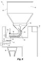
- dispenser chute 252 is formed by an electrically controlled conveyor 253 which collects material from the bottom opening of container 30 located directly above it and delivers it to a sloped surface 254 which leads the material, via the force of gravity, through trap door 255 and into receptacle 62.
- Trap door 255 preferably forms an air-tight seal which is opened only during operation in order to maintain the airtight seal of container 30, thereby protecting its contents.
- seal 55 is a door which closes to establish a seal below dispenser opening 54.
Landscapes
- Engineering & Computer Science (AREA)
- Mechanical Engineering (AREA)
- Food Science & Technology (AREA)
- Physics & Mathematics (AREA)
- General Physics & Mathematics (AREA)
- Apparatus For Making Beverages (AREA)
- Tea And Coffee (AREA)
- Beverage Vending Machines With Cups, And Gas Or Electricity Vending Machines (AREA)
- Devices For Dispensing Beverages (AREA)
- Basic Packing Technique (AREA)
Claims (15)
- Schüttgut-Abgabevorrichtung (20), die bedienbar ist, um eine ausgewählte Menge an losem Material abzugeben, wobei die Vorrichtung Folgendes umfasst:ein äußeres Gehäuse, das eine Behälterposition definiert, die zum Platzieren eines Behälters, in den das lose Material abgegeben werden soll, geeignet ist, wobei das äußere Gehäuse eine Auslassöffnung einschließt, die oberhalb der Behälterposition angeordnet ist,ein abgedichtetes Gehäuse (40) zum Aufbewahren des losen Materials,eine Benutzerschnittstelle (81; 85), die an dem äußeren Gehäuse angebracht ist,ein elektronisches Steuergerät (80) zum Empfangen einer Benutzerauswahl, die eine gewünschte Menge an losem Material, die abgegeben werden soll, über die Benutzerschnittstelle (81; 85) identifiziert undeinen Messmechanismus (50), angeordnet unterhalb des abgedichteten Gehäuses (40) und oberhalb der Auslassöffnung, der Folgendes umfasst:gekennzeichnet durchein Behältnis (62), das an einer Waage (64) angebracht ist, um so das Gewicht des gegenwärtig darin enthaltenen Materials für das elektronische Steuergerät (80) bereitzustellen und auf eine Aktivierung durch das elektronische Steuergerät (80) hin das darin enthaltene Material durch die Auslassöffnung freizugeben,eine Materialrutsche (52), die einen Einlass in abgedichteter Fluidverbindung mit dem Inneren des abgedichteten Gehäuses (40) und einen Auslass, der so angeordnet ist, dass er Material in das Behältnis (62) abgibt, hat,eine drehbare Schnecke (56), die durch einen Motor (57) angetrieben wird, der mit dem elektronischen Steuergerät (80) verbunden ist, wobei die drehbare Schnecke (56) innerhalb der Materialrutsche (52) angeordnet ist, um so eine steuerbare Abgabe des Materials in das Behältnis (62) zu gewährleisten, und
eine Abdichtungskappe (55), die dafür eingerichtet ist, mechanisch den Auslass der Materialrutsche (52) abzudichten, wenn die drehbare Schnecke (56) nicht in Betrieb ist. - Schüttgut-Abgabevorrichtung (20) nach Anspruch 1, wobei das abgedichtete Gehäuse hermetisch abgedichtet ist.
- Schüttgut-Abgabevorrichtung (20) nach Anspruch 1, wobei die Materialrutsche (52) eine Winkelform hat.
- Schüttgut-Abgabevorrichtung (20) nach Anspruch 2, wobei das elektronische Steuergerät (80) und der Messmechanismus (50) innerhalb des äußeren Gehäuses angeordnet sind, wobei wahlweise das abgedichtete Gehäuse (40) ein Rührwerk (54) einschließt, das während wenigstens eines Teils des Betriebs der Materialrutsche (52) arbeitet.
- Schüttgut-Abgabevorrichtung (20) nach Anspruch 1, wobei das lose Material Teeblätter sind.
- Schüttgut-Abgabevorrichtung (20) nach Anspruch 5, wobei die Benutzerschnittstelle (81; 85) Einstellungen ermöglicht, um das Volumen an Tee anzugeben, das zubereitet werden soll, wobei wahlweise die Benutzerschnittstelle (81; 85) eine Benutzerauswahl der Sorte von Tee, die abgegeben wird, ermöglicht und zwei unterschiedliche Gewichte für eine ausgewählte Menge an Tee, die zubereitet werden soll, in Verbindung mit jeder von zwei ausgewählten Teesorten speichert.
- Verfahren zum Abgeben einer von einem Benutzer ausgewählten Menge an losem Tee unter Verwendung einer Schüttgut-Abgabevorrichtung nach einem der Ansprüche 1, 9 oder 15 (20), das die folgenden Schritte umfasst:das Empfangen einer ersten Benutzereingabe über eine Benutzerschnittstelle (81; 85), die an der Abgabevorrichtung angeordnet ist, wobei die Benutzereingabe eine gewünschte Menge an Tee bezeichnet,das Empfangen einer zweiten Benutzereingabe über die Benutzerschnittstelle (81; 85), wobei die zweite Eingabe die gewünschte Menge an Tee um eine vorbestimmte Menge nach oben oder nach unten anpasst,das Empfangen eines Gewichts von einer Waage (64), die ein an derselben angebrachtes Behältnis (62) hat,das Weiterleiten von Tee aus einem abgedichteten Behälter (40) in das Behältnis (62), bis das von der Waage (64) empfangene Gewicht die gewünschte Menge erreicht oder überschreitet,das Abdichten des in dem abgedichteten Behälter (40) verbleibenden Tees gegenüber der Außenluft unddas Abgeben des Tees aus dem Behältnis (62) durch eine Auslassöffnung in der Abgabevorrichtung und das mechanische Abdichten des Auslasses durch eine Dichtung (55, 155, 255), wenn der Auslass nicht in Betrieb ist.
- Verfahren nach Anspruch 7,(i) wobei die zweite Benutzereingabe für einen stärkeren oder schwächeren Tee sorgt,(ii) wobei die zweite Benutzereingabe das gewünschte Volumen an Tee nach oben oder nach unten anpasst.
- Schüttgut-Abgabevorrichtung (20), die bedienbar ist, um eine ausgewählte Menge an losem Material abzugeben, wobei die Vorrichtung Folgendes umfasst:ein äußeres Gehäuse, das eine Behälterposition definiert, die zum Platzieren eines Behälters, in den das lose Material abgegeben werden soll, geeignet ist, wobei das äußere Gehäuse eine Auslassöffnung einschließt, die oberhalb der Behälterposition angeordnet ist,ein abgedichtetes Gehäuse (40) zum Aufbewahren des losen Materials,eine Benutzerschnittstelle (81; 85), die an dem äußeren Gehäuse angebracht ist,ein elektronisches Steuergerät (80) zum Empfangen einer Benutzerauswahl, die eine gewünschte Menge an losem Material, die abgegeben werden soll, über die Benutzerschnittstelle (81; 85) identifiziert undeinen Messmechanismus (50), angeordnet unterhalb des abgedichteten Gehäuses (40) und oberhalb der Auslassöffnung, der Folgendes umfasst:ein Behältnis (62), das an einer Waage (64) angebracht ist, um so das Gewicht des gegenwärtig darin enthaltenen Materials für das elektronische Steuergerät (80) bereitzustellen und auf eine Aktivierung durch das elektronische Steuergerät (80) hin das darin enthaltene Material durch die Auslassöffnung freizugeben,einen gesteuerten Auslass (52) in Fluidverbindung mit dem Gehäuse, wobei der gesteuerte Auslass (52) dafür eingerichtet ist, loses Material aus dem Gehäuse abzugeben, wenn er durch das elektronische Steuergerät (80) aktiviert wird,einen Förderer (253), der durch einen Motor (57) angetrieben wird, der mit dem elektronischen Steuergerät (80) verbunden ist, wobei der Förderer (253) unterhalb des gesteuerten Auslasses (52) angebracht und dafür konfiguriert ist, loses Material aus dem gesteuerten Auslass (52) aufzunehmen und das Material in das Behältnis (62) abzugeben,wobei der gesteuerte Auslass (52) dafür eingerichtet ist, mechanisch durch eine Dichtung (255) abgedichtet zu werden, wenn der Förderer (253) nicht in Betrieb ist.
- Schüttgut-Abgabevorrichtung (20) nach Anspruch 9, wobei das abgedichtete Gehäuse (40) ein Rührwerk (54) einschließt, das während wenigstens eines Teils des Betriebs des gesteuerten Auslasses (52) arbeitet.
- Schüttgut-Abgabevorrichtung (20) nach Anspruch 9, wobei das lose Material Teeblätter sind.
- Schüttgut-Abgabevorrichtung (20) nach Anspruch 11, wobei die Benutzerschnittstelle (81; 85) Einstellungen ermöglicht, um die Anzahl von Unzen an Tee anzugeben, die zubereitet werden soll.
- Schüttgut-Abgabevorrichtung (20) nach Anspruch 11, wobei die Benutzerschnittstelle (81; 85) dafür eingerichtet ist, Benutzereingaben zu empfangen, welche die Sorte von Tee, die innerhalb des Gehäuses (40) enthalten ist, angibt; wobei wahlweise die Benutzerschnittstelle (81; 85) eine Benutzerauswahl der Sorte von Tee, die abgegeben wird, ermöglicht und zwei unterschiedliche Gewichte für eine ausgewählte Menge an Tee, die zubereitet werden soll, in Verbindung mit jeder von zwei ausgewählten Teesorten speichert.
- Schüttgut-Abgabevorrichtung (20) nach Anspruch 13, wobei der gesteuerte Auslass (52) eine hermetische Abdichtung des Behälters bildet, wenn er nicht durch das elektronische Steuergerät (80) aktiviert wird.
- Schüttgut-Abgabevorrichtung (20), die bedienbar ist, um auf eine Aktivierung durch einen Benutzer hin eine vorbestimmte Menge an losem Material abzugeben, wobei die Vorrichtung Folgendes umfasst:ein äußeres Gehäuse, das eine Behälterposition definiert, die zum Platzieren eines Behälters, in den das lose Material abgegeben werden soll, geeignet ist, wobei das äußere Gehäuse eine Auslassöffnung einschließt, die oberhalb der Behälterposition angeordnet ist,ein abgedichtetes Gehäuse (40) zum Aufbewahren des losen Materials,eine Benutzerschnittstelle (81; 85), angebracht an dem äußeren Gehäuse, die dazu in der Lage ist, eine Benutzereingabe bezüglich einer ersten vorbestimmten Menge an losem Material zu empfangen und sie in Verbindung mit einem ersten von einem Benutzer auswählbaren Knopf zu speichern,einen Messmechanismus (50), angeordnet unterhalb des abgedichteten Gehäuses (40) und oberhalb der Auslassöffnung, der Folgendes umfasst:ein Behältnis (62), das an einer Waage angebracht ist, um so das Gewicht des gegenwärtig darin enthaltenen Materials für das elektronische Steuergerät (80) bereitzustellen und auf eine Aktivierung durch das elektronische Steuergerät (80) hin das darin enthaltene Material durch die Auslassöffnung freizugeben, undeinen gesteuerten Auslass in Fluidverbindung mit dem Gehäuse (40), wobei der gesteuerte Auslass dafür eingerichtet ist, loses Material aus dem Gehäuse (40) abzugeben, wenn er durch das elektronische Steuergerät (80) aktiviert wird, und der gesteuerte Auslass dafür eingerichtet ist, mechanisch durch eine Dichtung (55; 155; 255) abgedichtet zu werden, wenn der gesteuerte Auslass nicht in Betrieb ist, undein elektronisches Steuergerät (80) zum Empfangen einer Benutzerauswahl des ersten Knopfs über die Benutzerschnittstelle (81; 85) und als Reaktion Aktivieren des Messmechanismus (50), um die erste vorbestimmte Menge an losem Material abzugeben.
Applications Claiming Priority (2)
| Application Number | Priority Date | Filing Date | Title |
|---|---|---|---|
| US201161475723P | 2011-04-15 | 2011-04-15 | |
| PCT/US2012/033489 WO2012142390A2 (en) | 2011-04-15 | 2012-04-13 | System and method for dispensing a measured amount of a loose material |
Publications (3)
| Publication Number | Publication Date |
|---|---|
| EP2696731A2 EP2696731A2 (de) | 2014-02-19 |
| EP2696731A4 EP2696731A4 (de) | 2014-10-01 |
| EP2696731B1 true EP2696731B1 (de) | 2016-10-12 |
Family
ID=47009986
Family Applications (1)
| Application Number | Title | Priority Date | Filing Date |
|---|---|---|---|
| EP12771314.7A Active EP2696731B1 (de) | 2011-04-15 | 2012-04-13 | System und verfahren zur abgabe abgemessener mengen eines losen materials |
Country Status (13)
| Country | Link |
|---|---|
| US (2) | US9417114B2 (de) |
| EP (1) | EP2696731B1 (de) |
| JP (3) | JP2014510611A (de) |
| CN (1) | CN103732110B (de) |
| AU (1) | AU2012242665B2 (de) |
| BR (1) | BR112013026455B1 (de) |
| CA (1) | CA2832195C (de) |
| ES (1) | ES2610210T3 (de) |
| MX (1) | MX343531B (de) |
| PL (1) | PL2696731T3 (de) |
| RU (1) | RU2597545C2 (de) |
| SG (1) | SG194476A1 (de) |
| WO (1) | WO2012142390A2 (de) |
Families Citing this family (20)
| Publication number | Priority date | Publication date | Assignee | Title |
|---|---|---|---|---|
| US9851240B2 (en) * | 2008-03-06 | 2017-12-26 | Nicole Sollazzo Lee | Precision measurement dispenser |
| US20140131384A1 (en) * | 2012-11-12 | 2014-05-15 | Jose L MARTINEZ | Personal Cereal Dispenser |
| US20160207692A1 (en) * | 2012-11-12 | 2016-07-21 | Jose L. Martinez | Dry food dispenser |
| CN102987920B (zh) * | 2012-12-20 | 2015-05-13 | 朱楷 | 一种自动泡茶机 |
| NL2010318C2 (nl) * | 2013-02-18 | 2014-08-21 | Bravilor Holding Bv | Houder voor een drankbereidingsinrichting met een flexibel transportelement. |
| FR3011827B1 (fr) * | 2013-10-15 | 2016-05-27 | David Bouaziz | Dispositif de distribution de doses de produit a infuser. |
| WO2015077237A2 (en) * | 2013-11-20 | 2015-05-28 | Starbucks Corporation D/B/A Starbucks Coffee Company | Cooking system power management |
| CN107690570B (zh) * | 2015-05-19 | 2020-09-01 | 妮科尔·索拉佐·李 | 精密测量分配器 |
| CN105502264B (zh) * | 2016-01-08 | 2018-09-04 | 成都市天仁自动化科技有限公司 | 自动售液机上称量式出液计量系统及其计量方法 |
| DE102016100948A1 (de) * | 2016-01-20 | 2017-07-20 | Vorwerk & Co. Interholding Gmbh | Teeautomat, System und Verfahren zur Steuerung eines Teeautomaten |
| US10702839B2 (en) * | 2016-02-29 | 2020-07-07 | Nik of Time, Inc. | Precision dispensing and mixing apparatus |
| CN105852645A (zh) * | 2016-05-13 | 2016-08-17 | 深圳市元征科技股份有限公司 | 全自动泡茶机 |
| MD1214Z (ro) * | 2017-08-11 | 2018-07-31 | Андрей ПЕТРОВ | Dispozitiv pentru dozarea produselor alimentare vrac |
| USD877096S1 (en) * | 2017-12-11 | 2020-03-03 | Brita Gmbh | Dispensing device panel |
| JP7166626B2 (ja) * | 2019-10-21 | 2022-11-08 | 株式会社大都技研 | コーヒー飲料製造装置 |
| IT201900024847A1 (it) * | 2019-12-19 | 2021-06-19 | Delonghi Appliances Srl | Erogatore di prodotto sfuso |
| CN110974037B (zh) * | 2019-12-26 | 2021-12-28 | 珠海优特智厨科技有限公司 | 一种调料投放的检测方法及装置、存储介质、计算机设备 |
| CN113514137B (zh) * | 2021-06-21 | 2023-05-05 | 河南蓝天茶业有限公司 | 一种高精度茶叶计量装置 |
| JP7480803B2 (ja) * | 2022-05-06 | 2024-05-10 | 富士電機株式会社 | 原料払出装置 |
| CN116222669B (zh) * | 2023-04-23 | 2023-10-24 | 乐山市计量测试所 | 一种自动售水机的水质、计重实时监测系统及其监测方法 |
Family Cites Families (43)
| Publication number | Priority date | Publication date | Assignee | Title |
|---|---|---|---|---|
| US2643026A (en) * | 1947-04-02 | 1953-06-23 | Cragar Packaging Co Inc | Timer controlled apparatus adapted to feed and measure materials |
| FR2067486A5 (de) * | 1969-11-05 | 1971-08-20 | Cefilac | |
| JPS5017186Y1 (de) * | 1970-04-11 | 1975-05-27 | ||
| JPS5033325Y2 (de) * | 1971-04-08 | 1975-09-29 | ||
| US4013199A (en) | 1975-07-28 | 1977-03-22 | General Electric Company | Measuring dispenser |
| US4195753A (en) * | 1977-06-06 | 1980-04-01 | Dyer Clifford R | Dry chemical applicator |
| JPS54146591U (de) * | 1978-04-03 | 1979-10-12 | ||
| JPS56144941U (de) * | 1980-03-27 | 1981-10-31 | ||
| NL178776B (nl) * | 1984-10-03 | 1985-12-16 | Nelle Lassie Bv | Verpakking voor een consumptieartikel voorzien van een gecodeerde kaart. |
| JPS61291312A (ja) * | 1985-06-19 | 1986-12-22 | Tetsuo Murata | コンベヤ |
| US4665862A (en) * | 1985-12-27 | 1987-05-19 | Pitchford Jr Robert L | Timed automatic pet feed and water dispenser |
| US4683812A (en) | 1986-05-23 | 1987-08-04 | Brad Ridgley | Tea brewer and dispenser combination |
| US4723614A (en) * | 1986-06-24 | 1988-02-09 | Oy Maxi-Tuotanto Ab | Apparatus for automatically dispensing weight-controlled portions of granular foodstuff |
| EP0295035B1 (de) * | 1987-06-08 | 1993-04-21 | Ngk Insulators, Ltd. | Apparat zum Wiegen von pulvrigem Material |
| NL8800548A (nl) * | 1988-03-04 | 1989-10-02 | Koninklijke Olland Groep Bv | Drankenautomaat voor warme dranken. |
| DE3904376C2 (de) | 1989-02-14 | 1998-07-02 | Krups Fa Robert | Gerät zum Zubereiten von heißen Getränken, wie Kaffee, Tee od. dgl. |
| US5063757A (en) * | 1989-05-13 | 1991-11-12 | Kabushiki Kaisha Toshiba | Detergent dispenser for clothes washing machines or the like |
| JPH03237941A (ja) * | 1990-02-16 | 1991-10-23 | Mitsubishi Electric Corp | 給茶器 |
| JPH03242121A (ja) * | 1990-02-20 | 1991-10-29 | Mitsubishi Electric Corp | 給茶器 |
| JPH05120547A (ja) * | 1991-08-31 | 1993-05-18 | Sanyo Electric Co Ltd | 飲料供給装置 |
| DE4137324C1 (de) * | 1991-11-13 | 1993-02-04 | Cis Elektrogeraete Ag, Hinwil, Ch | |
| CN2132703Y (zh) * | 1992-06-06 | 1993-05-12 | 沈然 | 艺术型自动茶叶盒 |
| US5241898B1 (en) * | 1992-09-25 | 1999-02-09 | Grindmaster Corp | Coffee dispenser and brewer apparatus |
| EP0640311B1 (de) * | 1993-08-31 | 1998-01-28 | Jürgen Pilger | Vorrichtung zum Verpacken, zum Transport und zum kontrolliert dosierten Ausgeben einer körnigen oder pulverförmigen Ware |
| JP3090620B2 (ja) * | 1996-08-08 | 2000-09-25 | シーケーディ株式会社 | 小形粉末吐出装置 |
| AU7143098A (en) * | 1997-05-07 | 1998-11-27 | E.I. Du Pont De Nemours And Company | Measuring and dispensing system for solid dry flowable materials |
| EP0922425A1 (de) * | 1997-12-12 | 1999-06-16 | Braun Aktiengesellschaft | Brühgetränkezubereitungsmaschine |
| US6056027A (en) * | 1998-10-20 | 2000-05-02 | Murray Equipment, Inc. | Dry material dispensing apparatus |
| US6932245B2 (en) * | 2003-03-05 | 2005-08-23 | Nestec S.A. | Dispensing canister |
| WO2005048792A1 (en) | 2003-11-18 | 2005-06-02 | Gurbakshish Gill | Taste customizing beverage maker |
| RU38323U1 (ru) * | 2004-02-09 | 2004-06-10 | Игошин Павел Серафимович | Весовой дозатор для сыпучих материалов |
| JP2005245475A (ja) * | 2004-03-01 | 2005-09-15 | Tiger Vacuum Bottle Co Ltd | 飲料用粉茶等排出器 |
| EA010320B1 (ru) * | 2004-06-30 | 2008-08-29 | Хафер & Бёккер Охг | Фасовочная установка |
| US8032251B2 (en) | 2005-07-01 | 2011-10-04 | Koninklijke Philips Electronics N.V. | Control panel for hot beverage dispensing machines |
| CA2667383C (en) | 2006-10-24 | 2014-09-09 | A.C. Dispensing Equipment, Inc. | Auger-driven powder dispenser |
| US7912579B2 (en) * | 2007-01-10 | 2011-03-22 | Crane Merchandising Systems | Automatic cup detection and associated customer interface for vending apparatus and method therefor |
| NL2000662C2 (nl) * | 2007-05-24 | 2008-11-25 | Bravilor Holding Bv | Houdersamenstel voor een poedervormig ingredient ter bereiding van een instantdrank. |
| ATE454075T1 (de) * | 2008-01-30 | 2010-01-15 | Gruppo Cimbali Spa | Vorrichtung zur herstellung von getränken aus löslichen präparaten mit einer vorrichtung zur besseren aromaspeicherung |
| US8523014B2 (en) * | 2008-03-06 | 2013-09-03 | Nicole Sollazzo | Precision measurement dispenser |
| CN100584255C (zh) * | 2008-07-04 | 2010-01-27 | 唐仲湖 | 全自动泡茶桌 |
| CN101423137B (zh) * | 2008-12-09 | 2010-06-16 | 周利 | 自动落粉装置 |
| CN201325740Y (zh) * | 2008-12-23 | 2009-10-14 | 合肥美亚光电技术有限责任公司 | 一种挡板式履带提升机 |
| CN101849768B (zh) * | 2009-04-02 | 2012-07-25 | 上海天泰茶业科技有限公司 | 茶饮品制备设备 |
-
2012
- 2012-04-13 SG SG2013076336A patent/SG194476A1/en unknown
- 2012-04-13 JP JP2014505329A patent/JP2014510611A/ja not_active Withdrawn
- 2012-04-13 AU AU2012242665A patent/AU2012242665B2/en active Active
- 2012-04-13 RU RU2013147913/12A patent/RU2597545C2/ru active
- 2012-04-13 PL PL12771314T patent/PL2696731T3/pl unknown
- 2012-04-13 WO PCT/US2012/033489 patent/WO2012142390A2/en active Application Filing
- 2012-04-13 ES ES12771314.7T patent/ES2610210T3/es active Active
- 2012-04-13 CA CA2832195A patent/CA2832195C/en active Active
- 2012-04-13 CN CN201280018721.4A patent/CN103732110B/zh active Active
- 2012-04-13 EP EP12771314.7A patent/EP2696731B1/de active Active
- 2012-04-13 BR BR112013026455-1A patent/BR112013026455B1/pt active IP Right Grant
- 2012-04-13 MX MX2013011976A patent/MX343531B/es active IP Right Grant
-
2013
- 2013-10-15 US US14/053,721 patent/US9417114B2/en active Active
-
2016
- 2016-08-16 US US15/238,085 patent/US20170127873A1/en not_active Abandoned
-
2017
- 2017-03-06 JP JP2017041659A patent/JP2017140404A/ja not_active Withdrawn
-
2018
- 2018-12-03 JP JP2018226312A patent/JP6912444B2/ja active Active
Also Published As
| Publication number | Publication date |
|---|---|
| EP2696731A4 (de) | 2014-10-01 |
| US9417114B2 (en) | 2016-08-16 |
| CA2832195A1 (en) | 2012-10-18 |
| MX2013011976A (es) | 2014-10-15 |
| PL2696731T3 (pl) | 2017-05-31 |
| MX343531B (es) | 2016-11-09 |
| AU2012242665B2 (en) | 2016-12-22 |
| JP6912444B2 (ja) | 2021-08-04 |
| JP2014510611A (ja) | 2014-05-01 |
| US20140053946A1 (en) | 2014-02-27 |
| JP2019069164A (ja) | 2019-05-09 |
| CN103732110B (zh) | 2017-07-11 |
| JP2017140404A (ja) | 2017-08-17 |
| WO2012142390A2 (en) | 2012-10-18 |
| SG194476A1 (en) | 2013-12-30 |
| US20170127873A1 (en) | 2017-05-11 |
| CN103732110A (zh) | 2014-04-16 |
| BR112013026455B1 (pt) | 2020-12-15 |
| RU2597545C2 (ru) | 2016-09-10 |
| AU2012242665A1 (en) | 2013-10-17 |
| ES2610210T3 (es) | 2017-04-26 |
| WO2012142390A3 (en) | 2013-01-10 |
| EP2696731A2 (de) | 2014-02-19 |
| CA2832195C (en) | 2018-11-27 |
| BR112013026455A2 (pt) | 2016-12-27 |
| RU2013147913A (ru) | 2015-05-20 |
Similar Documents
| Publication | Publication Date | Title |
|---|---|---|
| EP2696731B1 (de) | System und verfahren zur abgabe abgemessener mengen eines losen materials | |
| US4789106A (en) | Combined coffee bean weigher and grinder with selectable measured quantities | |
| JP2024001331A (ja) | 正確な温度で制御された水を定量吐出するシステムおよび方法 | |
| JP2014510611A5 (de) | ||
| CN110651959A (zh) | 一种全自动爆米花机 | |
| CN210929507U (zh) | 一种全自动爆米花机 | |
| US20230346166A1 (en) | Method for dispensing ground coffee | |
| US20200069106A1 (en) | Coffee filter machine, and system which comprises the coffee filter machine | |
| EP3758563B1 (de) | Vorrichtung zum dosieren und ausgiessen einer menge gemahlenen kaffeepulvers in einen kaffeefilter einer kaffeemaschine | |
| US20230346154A1 (en) | System for dispensing ground coffee | |
| CN112243353B (zh) | 用于咖啡设备的单元 | |
| RU2782225C2 (ru) | Блок для кофейного аппарата |
Legal Events
| Date | Code | Title | Description |
|---|---|---|---|
| PUAI | Public reference made under article 153(3) epc to a published international application that has entered the european phase |
Free format text: ORIGINAL CODE: 0009012 |
|
| 17P | Request for examination filed |
Effective date: 20130930 |
|
| AK | Designated contracting states |
Kind code of ref document: A2 Designated state(s): AL AT BE BG CH CY CZ DE DK EE ES FI FR GB GR HR HU IE IS IT LI LT LU LV MC MK MT NL NO PL PT RO RS SE SI SK SM TR |
|
| REG | Reference to a national code |
Ref country code: HK Ref legal event code: DE Ref document number: 1188915 Country of ref document: HK |
|
| DAX | Request for extension of the european patent (deleted) | ||
| A4 | Supplementary search report drawn up and despatched |
Effective date: 20140901 |
|
| RIC1 | Information provided on ipc code assigned before grant |
Ipc: B65D 83/06 20060101ALI20140826BHEP Ipc: B65G 47/18 20060101ALI20140826BHEP Ipc: B65G 65/30 20060101ALI20140826BHEP Ipc: A47J 31/40 20060101AFI20140826BHEP |
|
| GRAP | Despatch of communication of intention to grant a patent |
Free format text: ORIGINAL CODE: EPIDOSNIGR1 |
|
| INTG | Intention to grant announced |
Effective date: 20160428 |
|
| GRAS | Grant fee paid |
Free format text: ORIGINAL CODE: EPIDOSNIGR3 |
|
| GRAA | (expected) grant |
Free format text: ORIGINAL CODE: 0009210 |
|
| AK | Designated contracting states |
Kind code of ref document: B1 Designated state(s): AL AT BE BG CH CY CZ DE DK EE ES FI FR GB GR HR HU IE IS IT LI LT LU LV MC MK MT NL NO PL PT RO RS SE SI SK SM TR |
|
| REG | Reference to a national code |
Ref country code: GB Ref legal event code: FG4D |
|
| REG | Reference to a national code |
Ref country code: CH Ref legal event code: EP |
|
| REG | Reference to a national code |
Ref country code: AT Ref legal event code: REF Ref document number: 835669 Country of ref document: AT Kind code of ref document: T Effective date: 20161015 |
|
| REG | Reference to a national code |
Ref country code: IE Ref legal event code: FG4D |
|
| REG | Reference to a national code |
Ref country code: DE Ref legal event code: R096 Ref document number: 602012024082 Country of ref document: DE |
|
| REG | Reference to a national code |
Ref country code: NL Ref legal event code: FP |
|
| REG | Reference to a national code |
Ref country code: LT Ref legal event code: MG4D |
|
| REG | Reference to a national code |
Ref country code: SE Ref legal event code: TRGR |
|
| REG | Reference to a national code |
Ref country code: CH Ref legal event code: NV Representative=s name: SERVOPATENT GMBH, CH |
|
| PG25 | Lapsed in a contracting state [announced via postgrant information from national office to epo] |
Ref country code: LV Free format text: LAPSE BECAUSE OF FAILURE TO SUBMIT A TRANSLATION OF THE DESCRIPTION OR TO PAY THE FEE WITHIN THE PRESCRIBED TIME-LIMIT Effective date: 20161012 |
|
| REG | Reference to a national code |
Ref country code: FR Ref legal event code: PLFP Year of fee payment: 6 |
|
| REG | Reference to a national code |
Ref country code: AT Ref legal event code: MK05 Ref document number: 835669 Country of ref document: AT Kind code of ref document: T Effective date: 20161012 |
|
| REG | Reference to a national code |
Ref country code: ES Ref legal event code: FG2A Ref document number: 2610210 Country of ref document: ES Kind code of ref document: T3 Effective date: 20170426 |
|
| PG25 | Lapsed in a contracting state [announced via postgrant information from national office to epo] |
Ref country code: LT Free format text: LAPSE BECAUSE OF FAILURE TO SUBMIT A TRANSLATION OF THE DESCRIPTION OR TO PAY THE FEE WITHIN THE PRESCRIBED TIME-LIMIT Effective date: 20161012 Ref country code: NO Free format text: LAPSE BECAUSE OF FAILURE TO SUBMIT A TRANSLATION OF THE DESCRIPTION OR TO PAY THE FEE WITHIN THE PRESCRIBED TIME-LIMIT Effective date: 20170112 Ref country code: GR Free format text: LAPSE BECAUSE OF FAILURE TO SUBMIT A TRANSLATION OF THE DESCRIPTION OR TO PAY THE FEE WITHIN THE PRESCRIBED TIME-LIMIT Effective date: 20170113 |
|
| PG25 | Lapsed in a contracting state [announced via postgrant information from national office to epo] |
Ref country code: AT Free format text: LAPSE BECAUSE OF FAILURE TO SUBMIT A TRANSLATION OF THE DESCRIPTION OR TO PAY THE FEE WITHIN THE PRESCRIBED TIME-LIMIT Effective date: 20161012 Ref country code: FI Free format text: LAPSE BECAUSE OF FAILURE TO SUBMIT A TRANSLATION OF THE DESCRIPTION OR TO PAY THE FEE WITHIN THE PRESCRIBED TIME-LIMIT Effective date: 20161012 Ref country code: HR Free format text: LAPSE BECAUSE OF FAILURE TO SUBMIT A TRANSLATION OF THE DESCRIPTION OR TO PAY THE FEE WITHIN THE PRESCRIBED TIME-LIMIT Effective date: 20161012 Ref country code: BE Free format text: LAPSE BECAUSE OF FAILURE TO SUBMIT A TRANSLATION OF THE DESCRIPTION OR TO PAY THE FEE WITHIN THE PRESCRIBED TIME-LIMIT Effective date: 20161012 Ref country code: IS Free format text: LAPSE BECAUSE OF FAILURE TO SUBMIT A TRANSLATION OF THE DESCRIPTION OR TO PAY THE FEE WITHIN THE PRESCRIBED TIME-LIMIT Effective date: 20170212 Ref country code: PT Free format text: LAPSE BECAUSE OF FAILURE TO SUBMIT A TRANSLATION OF THE DESCRIPTION OR TO PAY THE FEE WITHIN THE PRESCRIBED TIME-LIMIT Effective date: 20170213 Ref country code: RS Free format text: LAPSE BECAUSE OF FAILURE TO SUBMIT A TRANSLATION OF THE DESCRIPTION OR TO PAY THE FEE WITHIN THE PRESCRIBED TIME-LIMIT Effective date: 20161012 |
|
| REG | Reference to a national code |
Ref country code: DE Ref legal event code: R097 Ref document number: 602012024082 Country of ref document: DE |
|
| PG25 | Lapsed in a contracting state [announced via postgrant information from national office to epo] |
Ref country code: DK Free format text: LAPSE BECAUSE OF FAILURE TO SUBMIT A TRANSLATION OF THE DESCRIPTION OR TO PAY THE FEE WITHIN THE PRESCRIBED TIME-LIMIT Effective date: 20161012 Ref country code: SK Free format text: LAPSE BECAUSE OF FAILURE TO SUBMIT A TRANSLATION OF THE DESCRIPTION OR TO PAY THE FEE WITHIN THE PRESCRIBED TIME-LIMIT Effective date: 20161012 Ref country code: EE Free format text: LAPSE BECAUSE OF FAILURE TO SUBMIT A TRANSLATION OF THE DESCRIPTION OR TO PAY THE FEE WITHIN THE PRESCRIBED TIME-LIMIT Effective date: 20161012 Ref country code: RO Free format text: LAPSE BECAUSE OF FAILURE TO SUBMIT A TRANSLATION OF THE DESCRIPTION OR TO PAY THE FEE WITHIN THE PRESCRIBED TIME-LIMIT Effective date: 20161012 |
|
| PLBE | No opposition filed within time limit |
Free format text: ORIGINAL CODE: 0009261 |
|
| STAA | Information on the status of an ep patent application or granted ep patent |
Free format text: STATUS: NO OPPOSITION FILED WITHIN TIME LIMIT |
|
| PG25 | Lapsed in a contracting state [announced via postgrant information from national office to epo] |
Ref country code: BG Free format text: LAPSE BECAUSE OF FAILURE TO SUBMIT A TRANSLATION OF THE DESCRIPTION OR TO PAY THE FEE WITHIN THE PRESCRIBED TIME-LIMIT Effective date: 20170112 Ref country code: SM Free format text: LAPSE BECAUSE OF FAILURE TO SUBMIT A TRANSLATION OF THE DESCRIPTION OR TO PAY THE FEE WITHIN THE PRESCRIBED TIME-LIMIT Effective date: 20161012 |
|
| 26N | No opposition filed |
Effective date: 20170713 |
|
| REG | Reference to a national code |
Ref country code: HK Ref legal event code: GR Ref document number: 1188915 Country of ref document: HK |
|
| PG25 | Lapsed in a contracting state [announced via postgrant information from national office to epo] |
Ref country code: SI Free format text: LAPSE BECAUSE OF FAILURE TO SUBMIT A TRANSLATION OF THE DESCRIPTION OR TO PAY THE FEE WITHIN THE PRESCRIBED TIME-LIMIT Effective date: 20161012 |
|
| PG25 | Lapsed in a contracting state [announced via postgrant information from national office to epo] |
Ref country code: MC Free format text: LAPSE BECAUSE OF FAILURE TO SUBMIT A TRANSLATION OF THE DESCRIPTION OR TO PAY THE FEE WITHIN THE PRESCRIBED TIME-LIMIT Effective date: 20161012 |
|
| PG25 | Lapsed in a contracting state [announced via postgrant information from national office to epo] |
Ref country code: LU Free format text: LAPSE BECAUSE OF NON-PAYMENT OF DUE FEES Effective date: 20170413 |
|
| REG | Reference to a national code |
Ref country code: FR Ref legal event code: PLFP Year of fee payment: 7 |
|
| PG25 | Lapsed in a contracting state [announced via postgrant information from national office to epo] |
Ref country code: MT Free format text: LAPSE BECAUSE OF NON-PAYMENT OF DUE FEES Effective date: 20170413 |
|
| PG25 | Lapsed in a contracting state [announced via postgrant information from national office to epo] |
Ref country code: HU Free format text: LAPSE BECAUSE OF FAILURE TO SUBMIT A TRANSLATION OF THE DESCRIPTION OR TO PAY THE FEE WITHIN THE PRESCRIBED TIME-LIMIT; INVALID AB INITIO Effective date: 20120413 |
|
| PG25 | Lapsed in a contracting state [announced via postgrant information from national office to epo] |
Ref country code: CY Free format text: LAPSE BECAUSE OF NON-PAYMENT OF DUE FEES Effective date: 20161012 |
|
| PG25 | Lapsed in a contracting state [announced via postgrant information from national office to epo] |
Ref country code: MK Free format text: LAPSE BECAUSE OF FAILURE TO SUBMIT A TRANSLATION OF THE DESCRIPTION OR TO PAY THE FEE WITHIN THE PRESCRIBED TIME-LIMIT Effective date: 20161012 |
|
| REG | Reference to a national code |
Ref country code: CH Ref legal event code: PCAR Free format text: NEW ADDRESS: WANNERSTRASSE 9/1, 8045 ZUERICH (CH) |
|
| PG25 | Lapsed in a contracting state [announced via postgrant information from national office to epo] |
Ref country code: AL Free format text: LAPSE BECAUSE OF FAILURE TO SUBMIT A TRANSLATION OF THE DESCRIPTION OR TO PAY THE FEE WITHIN THE PRESCRIBED TIME-LIMIT Effective date: 20161012 |
|
| PGFP | Annual fee paid to national office [announced via postgrant information from national office to epo] |
Ref country code: NL Payment date: 20240315 Year of fee payment: 13 Ref country code: IE Payment date: 20240312 Year of fee payment: 13 |
|
| PGFP | Annual fee paid to national office [announced via postgrant information from national office to epo] |
Ref country code: GB Payment date: 20240229 Year of fee payment: 13 |
|
| PGFP | Annual fee paid to national office [announced via postgrant information from national office to epo] |
Ref country code: SE Payment date: 20240312 Year of fee payment: 13 Ref country code: PL Payment date: 20240305 Year of fee payment: 13 Ref country code: IT Payment date: 20240313 Year of fee payment: 13 Ref country code: FR Payment date: 20240308 Year of fee payment: 13 |
|
| PGFP | Annual fee paid to national office [announced via postgrant information from national office to epo] |
Ref country code: DE Payment date: 20240306 Year of fee payment: 13 |
|
| PGFP | Annual fee paid to national office [announced via postgrant information from national office to epo] |
Ref country code: CH Payment date: 20240501 Year of fee payment: 13 |
|
| PGFP | Annual fee paid to national office [announced via postgrant information from national office to epo] |
Ref country code: ES Payment date: 20240507 Year of fee payment: 13 |
|
| PGFP | Annual fee paid to national office [announced via postgrant information from national office to epo] |
Ref country code: CZ Payment date: 20240402 Year of fee payment: 13 |
|
| PGFP | Annual fee paid to national office [announced via postgrant information from national office to epo] |
Ref country code: TR Payment date: 20240402 Year of fee payment: 13 |