EP2696166A2 - Optische Messvorrichtung und Sonde - Google Patents
Optische Messvorrichtung und Sonde Download PDFInfo
- Publication number
- EP2696166A2 EP2696166A2 EP13178647.7A EP13178647A EP2696166A2 EP 2696166 A2 EP2696166 A2 EP 2696166A2 EP 13178647 A EP13178647 A EP 13178647A EP 2696166 A2 EP2696166 A2 EP 2696166A2
- Authority
- EP
- European Patent Office
- Prior art keywords
- light
- measurement device
- photo detector
- optical measurement
- light source
- Prior art date
- Legal status (The legal status is an assumption and is not a legal conclusion. Google has not performed a legal analysis and makes no representation as to the accuracy of the status listed.)
- Withdrawn
Links
- 230000003287 optical effect Effects 0.000 title claims abstract description 245
- 238000005259 measurement Methods 0.000 title claims abstract description 142
- 238000003384 imaging method Methods 0.000 claims abstract description 126
- 238000001514 detection method Methods 0.000 claims description 55
- 230000008878 coupling Effects 0.000 description 95
- 238000010168 coupling process Methods 0.000 description 95
- 238000005859 coupling reaction Methods 0.000 description 95
- 238000010586 diagram Methods 0.000 description 28
- 239000004065 semiconductor Substances 0.000 description 8
- 230000000694 effects Effects 0.000 description 7
- 230000006870 function Effects 0.000 description 4
- 238000012986 modification Methods 0.000 description 4
- 230000004048 modification Effects 0.000 description 4
- 230000008901 benefit Effects 0.000 description 2
- 238000000034 method Methods 0.000 description 2
- 230000004044 response Effects 0.000 description 1
- 239000007787 solid Substances 0.000 description 1
Images


Classifications
-
- G—PHYSICS
- G01—MEASURING; TESTING
- G01J—MEASUREMENT OF INTENSITY, VELOCITY, SPECTRAL CONTENT, POLARISATION, PHASE OR PULSE CHARACTERISTICS OF INFRARED, VISIBLE OR ULTRAVIOLET LIGHT; COLORIMETRY; RADIATION PYROMETRY
- G01J1/00—Photometry, e.g. photographic exposure meter
- G01J1/02—Details
- G01J1/04—Optical or mechanical part supplementary adjustable parts
- G01J1/0407—Optical elements not provided otherwise, e.g. manifolds, windows, holograms, gratings
- G01J1/0422—Optical elements not provided otherwise, e.g. manifolds, windows, holograms, gratings using light concentrators, collectors or condensers
-
- G—PHYSICS
- G01—MEASURING; TESTING
- G01C—MEASURING DISTANCES, LEVELS OR BEARINGS; SURVEYING; NAVIGATION; GYROSCOPIC INSTRUMENTS; PHOTOGRAMMETRY OR VIDEOGRAMMETRY
- G01C3/00—Measuring distances in line of sight; Optical rangefinders
- G01C3/02—Details
- G01C3/06—Use of electric means to obtain final indication
- G01C3/08—Use of electric radiation detectors
-
- G—PHYSICS
- G01—MEASURING; TESTING
- G01S—RADIO DIRECTION-FINDING; RADIO NAVIGATION; DETERMINING DISTANCE OR VELOCITY BY USE OF RADIO WAVES; LOCATING OR PRESENCE-DETECTING BY USE OF THE REFLECTION OR RERADIATION OF RADIO WAVES; ANALOGOUS ARRANGEMENTS USING OTHER WAVES
- G01S17/00—Systems using the reflection or reradiation of electromagnetic waves other than radio waves, e.g. lidar systems
- G01S17/02—Systems using the reflection of electromagnetic waves other than radio waves
- G01S17/06—Systems determining position data of a target
- G01S17/42—Simultaneous measurement of distance and other co-ordinates
-
- G—PHYSICS
- G01—MEASURING; TESTING
- G01S—RADIO DIRECTION-FINDING; RADIO NAVIGATION; DETERMINING DISTANCE OR VELOCITY BY USE OF RADIO WAVES; LOCATING OR PRESENCE-DETECTING BY USE OF THE REFLECTION OR RERADIATION OF RADIO WAVES; ANALOGOUS ARRANGEMENTS USING OTHER WAVES
- G01S17/00—Systems using the reflection or reradiation of electromagnetic waves other than radio waves, e.g. lidar systems
- G01S17/88—Lidar systems specially adapted for specific applications
- G01S17/93—Lidar systems specially adapted for specific applications for anti-collision purposes
- G01S17/931—Lidar systems specially adapted for specific applications for anti-collision purposes of land vehicles
-
- G—PHYSICS
- G01—MEASURING; TESTING
- G01S—RADIO DIRECTION-FINDING; RADIO NAVIGATION; DETERMINING DISTANCE OR VELOCITY BY USE OF RADIO WAVES; LOCATING OR PRESENCE-DETECTING BY USE OF THE REFLECTION OR RERADIATION OF RADIO WAVES; ANALOGOUS ARRANGEMENTS USING OTHER WAVES
- G01S7/00—Details of systems according to groups G01S13/00, G01S15/00, G01S17/00
- G01S7/48—Details of systems according to groups G01S13/00, G01S15/00, G01S17/00 of systems according to group G01S17/00
- G01S7/481—Constructional features, e.g. arrangements of optical elements
- G01S7/4811—Constructional features, e.g. arrangements of optical elements common to transmitter and receiver
-
- G—PHYSICS
- G01—MEASURING; TESTING
- G01S—RADIO DIRECTION-FINDING; RADIO NAVIGATION; DETERMINING DISTANCE OR VELOCITY BY USE OF RADIO WAVES; LOCATING OR PRESENCE-DETECTING BY USE OF THE REFLECTION OR RERADIATION OF RADIO WAVES; ANALOGOUS ARRANGEMENTS USING OTHER WAVES
- G01S7/00—Details of systems according to groups G01S13/00, G01S15/00, G01S17/00
- G01S7/48—Details of systems according to groups G01S13/00, G01S15/00, G01S17/00 of systems according to group G01S17/00
- G01S7/481—Constructional features, e.g. arrangements of optical elements
- G01S7/4814—Constructional features, e.g. arrangements of optical elements of transmitters alone
- G01S7/4815—Constructional features, e.g. arrangements of optical elements of transmitters alone using multiple transmitters
-
- G—PHYSICS
- G01—MEASURING; TESTING
- G01S—RADIO DIRECTION-FINDING; RADIO NAVIGATION; DETERMINING DISTANCE OR VELOCITY BY USE OF RADIO WAVES; LOCATING OR PRESENCE-DETECTING BY USE OF THE REFLECTION OR RERADIATION OF RADIO WAVES; ANALOGOUS ARRANGEMENTS USING OTHER WAVES
- G01S7/00—Details of systems according to groups G01S13/00, G01S15/00, G01S17/00
- G01S7/48—Details of systems according to groups G01S13/00, G01S15/00, G01S17/00 of systems according to group G01S17/00
- G01S7/481—Constructional features, e.g. arrangements of optical elements
- G01S7/4817—Constructional features, e.g. arrangements of optical elements relating to scanning
Definitions
- the present invention relates to an optical measurement device and a vehicle to which the optical measurement device is mounted.
- the optical measurement device detects the presence or absence of an object, and measures a distance from the optical measurement device to the object.
- the optical measurement device can be used for factory automation (FA), for security, or for automotive usage.
- An optical measurement device which detects the presence or absence of an object, and which measures a distance to the object.
- the following device may be considered. Namely, the device scans a predetermined measurement field with a light beam by deflecting the light beam by a rotating polygonal mirror. The device receives the light, which is reflected by a measured object in the measurement field, with a photo detector by continuously changing a viewing angle by using the same rotating polygonal mirror, and thereby the device measures a distance to the scanning point (e.g., Patent Document 1 (Japanese Unexamined Patent Publication No. H11-304469 )).
- a light beam from a semiconductor laser as a light source is converted into parallel light by an optical element (a transmitter lens). It is also described that a light beam is narrowed down onto a position sensitive device (PSD), which is a photo detector, by using an imaging means (a receiver lens). Although it is not explicitly described, it implies that the PSD is disposed at a position of a focal length of the receiver lens.
- PSD position sensitive device
- a distance between an object point (the light source or the photo detector) and a lens (the transmitter lens or the receiver lens) is set to be the focal length of the lens.
- This setting implies that a conjugate image of the object point can be formed at infinity.
- the object point is blurred, and a desired resolution may not be achieved.
- an optical measurement device including
- an optical measurement device which has higher angular resolution in the vicinity of the device.
- an optical measurement device includes, for example, a device that irradiates light to a predetermined region, and that determines presence or absence of an object in the predetermined region based on reflected light or scattered light. Further, in the present application, an optical measurement device includes, for example, a device that irradiates light to an object, and that measures a distance to the object based on reflected light or scattered light, when the presence of the object in a predetermined region is determined.
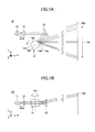
- FIGS. 1A and 1B are schematic diagrams exemplifying a projection optical system of an optical measurement device according to an example.
- FIG. 1A shows a cross-section in a direction parallel to an XY-plane.
- FIG. 1B shows a cross-section in a direction parallel to an XZ-plane.
- FIGS. 2A and 2B are schematic diagrams exemplifying a receiving optical system of the optical measurement device according to the example.
- FIG. 2A shows a cross-section in a direction parallel to the XY-plane.
- FIG. 2B shows a cross-section in a direction parallel to the XZ-plane.
- the optical measurement device 10 includes a light source 11; a coupling lens 12; a reflection mirror 13; a rotating mirror 14; a reflection mirror 15; an imaging lens 16; and a photo detector 17.
- the reference numeral "100” indicates an image surface of an object, which is a detection target.
- the reference numeral "110" indicates a detection range.
- coordinate axes are defined such that an axis from the rotation mirror 14 to the center of the detection range 110 is defined to be an X-axis, an axis parallel to a direction in which the rotating mirror 14 scans a light beam is defined to be a Y-axis, and a direction of a rotation axis of the rotating mirror 14 is defined to be a Z-axis.
- the coordinate axes define a three-dimensional orthogonal coordinate system (the coordinate axes are defined in the same manner in the remaining figures).
- a direction in which the rotating mirror 14, which is a deflector, deflects and scans a light beam may be referred to as a "main scanning directian,” and a direction which is perpendicular to the main scanning direction may be referred to as a "sub-scanning direction.”
- a solid light source such as a semiconductor laser or a light-emitting diode.
- the semiconductor laser is used as the light source 11. An explanation is given by exemplifying a case in which the semiconductor laser is caused to perform pulse light emission.
- the coupling lens 12 is disposed downstream of the light source 11.
- the coupling lens 12 may include a combination of a plurality of optical elements.
- the coupling lens 12 has a function to condense a light beam (diverging light) which is emitted from the light source 11.
- a focal length in the main scanning direction of the coupling lens 12 and a focal length in the sub-scanning direction of the coupling lens 12 are the same (which is denoted as a focal length f 1 ).
- a distance between the light emitting part of the light source 11 and a first principal point of the coupling lens 12 is defined to be L 1 .
- a point at which a principal plane of the coupling lens 12 and the optical axis cross at right angles is defined to be the first principal point.
- the light source 11 and the coupling lens 12 are arranged such that the distance L 1 is equal to the focal length f 1 of the coupling lens 12 in the main scanning direction.
- the coupling lens 12 is arranged such that the first principal point is separated from the light emitting part of the light source 11 by a distance which is equal to the focal length f 1 (the light source 11 and the coupling lens 12 are arranged such that a conjugate image of the light source is formed at infinity).
- “equal means not only a case of strictly equal, but also a case of approximately equal to the extent that a predetermined effect of the present application is not lost.
- the light source 11 and the coupling lens 12 are arranged, so that the distance L 1 between the light emitting part of the light source 11 and the first principal point of the coupling lens 12 is equal to the focal length f 1 of the coupling lens 12.
- the coupling lens 12 is arranged such that the first principal point is separated from the light emitting part of the light source 11 by the focal length f 1 (the light source 11 and the coupling lens 12 are arranged such that the conjugate image of the light source 11 is formed at infinity).
- the coupling lens 12 is arranged so that the diverging light which is emitted from the light source 11 becomes substantially parallel light. Actually, due to an effect of a light emitting region of the light source 11 (the semiconductor laser), light which passes through the coupling lens 12 becomes the diverging light. Details of this point are described later.
- the light which passes through the coupling lens 12 enters the reflection mirror 13, and thereby the optical path of the light is converted by the reflection mirror 13. Then the light enters the rotating mirror 14.
- An angular difference on the XY-plane between the light which enters the reflection mirror 13 and the light which is reflected by the reflection mirror 13 may be set to be approximately 60 degrees, for example.
- the rotating mirror 14 includes at least two reflectors (reflection surfaces). Each of the reflectors are obliquely arranged with respect to the rotation axis 14o. The reflectors are tilted with respect to the rotation axis 14o by corresponding different angles.
- the coupling lens 12 is a typical example of an optical element according to the embodiment of the present invention.
- the light source 11 and the coupling lens 12 are a typical example of a light irradiator according to the embodiment of the present invention.
- the rotating mirror 14 is a typical example of a deflector according to the embodiment of the present invention.
- the rotating mirror 14 includes four reflectors 14a, 14b, 14c, and 14d. Tilt angles of the corresponding reflectors 14a, 14b, 14c, and 14d with respect to the rotation axis 14o are set to be different angles. With this configuration, a traveling direction of the light which is reflected by the rotating mirror 14 with respect to the XY-plane can be switched. A layer which is to be detected can be shifted in the Z-axis direction for each of the reflectors 14a, 14b, 14c, and 14d. Namely, for the reflectors 14a, 14b, 14c, and 14d, corresponding regions, which are different regions in the Z-axis direction, are scanned. For the case of this example, four layers can be detected.
- the light which enters the rotating mirror 14 is deflected and scanned by the rotating reflectors 14a, 14b, 14c, and 14d, and the light irradiates the detection range 110 of the image surface 100.
- the reflected light or the scattered light from the detection range 110 of the image surface 100 enters the rotating mirror 14 again. Then, the reflected light or the scattered light is sequentially reflected by the reflector 14a, 14b, 14c, and 14d, and the reflected light or the scattered light is reflected by the reflection mirror 15 again. Then, the reflected light or the scattered light enters the imaging lens 16.
- the imaging lens 16 has a function to cause the reflected light or the scattered light from the detection range 110 of the image surface 100 to form an image.
- a focal length in the main scanning direction of the imaging lens 16 and a focal length in the sub-scanning direction of the imaging lens 16 are the same (which is denoted as a focal length f 2 ).
- the imaging lens 16 is a typical example of an imaging optical system according to the embodiment of the present invention- Further, the imaging lens 16 is a typical example of a first imaging element according to the embodiment of the present invention.
- the reflected light or the scattered light from the detection range 110 of the image surface 100 which passes through the imaging lens 16 enters the photo detector 17.
- the photo detector 17 has a function to detect the reflected light or the scatter light through the imaging lens 16.
- the reflected light or the scattered light is originated from the light beam which is irradiated onto the detection range 110 of the image surface 100.
- an avalanche photodiode (APD) or a pin photodiode (PD) may be used as the photo detector 17.
- the receiving optical system may be formed of a lens and a photo detector, without using a rotating mirror.
- a distance from a light receiving part of the photo detector 17 and a second principal point of the imaging lens 16 is defined to be L 2 .
- a point at which a principal plane of the imaging lens 16 and the optical axis cross at right angles is defined to be the second principal point.
- the photo detector 17 and the imaging lens 16 are arranged such that, in the main scanning direction, the distance L 2 becomes greater than the focal length f 2 of the imaging lens 16.
- the imaging lens 16 is arranged such that the distance between the second principal point of the imaging lens 16 and the light receiving part of the photo detector 17 is greater than the focal length f 2 .
- the photo detector 17 and the imaging lens 16 are arranged such that a distance L 2 from the light receiving part of the photo detector 17 to the second principal point of the imaging lens 16 is greater than the focal length f 2 of the imaging lens 16.
- the imaging lens 16 is arranged such that the distance between the second principal point and the light receiving part of the photo detector 17 is greater than the focal length f 2 .
- the imaging lens 16 is arranged such that, if it is assumed that a light beam is emitted from the photo detector 17, the light beam converges at a predetermined position.
- L 3 indicates a minimum detection distance, which is the closest detection distance to an object with which the optical measurement device 10 can detect the object.
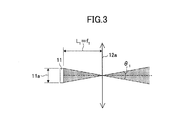
- FIG. 3 is a diagram exemplifying an irradiated region of the light source 11, when the light emitting region of the light source is considered.
- the distance between the light emitting part of the light source 11 to the first principal point of the coupling lens 12 is L 1 .
- the first principal point is the point at which the principal plane 12a of the coupling lens 12 (which is denoted by the arrows in FIG. 3 ) and the optical axis of the coupling lens 12 cross at right angles.
- the light source 11 and the coupling lens 12 are arranged such that, in the main scanning direction and in the sub-scanning direction, the distance L 1 is equal to the focal length f 1 of the coupling lens 12.
- the angular range ⁇ 1 is the irradiated region by the light emitting region 11a of the light source 11.
- an angular resolution of a region in which an object is detected is defined in terms of a beam divergence angle, which is shown in FIG. 3 .
- ⁇ 1 can be expressed by a formula where the focal length f 1 of the coupling lens 12 is replaced by the distance L 1 from the light emitting part of the light source 11 to the first principal point, at which the principal plane 12a of the coupling lens 12 and the optical axis of the coupling lens 12 cross at right angles.
- FIGS. 4A and 4B are diagrams exemplifying an irradiated region of the light source, when the light emitting region of the light source and the effective range of the coupling lens is considered.
- FIG. 4A shows the vicinity of the optical measurement device (the vicinity of the coupling lens 12).
- FIG. 4B shows a distant region of the optical measurement device (the distant region of the coupling lens 12).
- an effect of off-axis light becomes large especially in the vicinity of the optical measurement device (the vicinity of the coupling lens 12), as shown in FIG. 4A .
- an imaging range 11x becomes wider than the irradiated region (which is indicated by the stain pattern in FIGS. 4A and 4B ) by the light emitting region 11a of the light source 11, which is shown in FIG. 3 .
- ⁇ 2 becomes greater than ⁇ 1 , and the angular resolution is expanded (degraded) as indicated by the middle bold lines in FIGS. 4A and 4B .
- the farther away the coupling lens 12 is the more the irradiated region by the light emitting region 11a of the light source and the imaging range 11x are approximated.
- the irradiated region and the imaging range 11x coincide at infinity. Namely, the farther away the coupling lens 12 is, the more the values of ⁇ 2 and ⁇ 1 are approximated (the angular resolutions are approximated). At infinity, ⁇ 2 becomes equal to ⁇ 1 , and the angular resolutions completely coincide.
- the effective range 12b of the coupling lens 12 is considered.
- the effective range 12b of the coupling lens 12 is sufficiently larger compared to the divergence angle of the light source 11, the off-axis light of the light source 11 is defined by the divergence angle.
- the angular resolution is degraded.
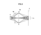
- FIG. 5 is a schematic diagram exemplifying the details of the receiving optical system of the optical measurement device according to the example.
- the reference numeral 16a indicates the principal plane of the imaging lens 16
- the reference numeral 16b indicates an effective range of the imaging lens 16
- the reference numeral 17x indicates an imaging range of the photo detector 17
- A indicates a focus surface.
- the focus surface is a surface including a predetermined point at which a light beam converges, if it is assumed that the light beam is emitted from the photo detector 17.
- the angular resolution in the vicinity of the optical measurement device is improved by the configuration of the receiving optical system such that, when the photo detector 17 is assumed to be an object point, an image of the photo detector 17 is formed by the imaging lens 16, as shown in FIG. 5 .
- the area in which an object can be detected is the area where an image of the light source 11 and an image of the photo detector 17 overlap. For example, even if an area is inside the image of the light source, namely, even if the area is inside the irradiated region by the light source 11, if the area is outside the image of the photo detector 17, the reflected light from that area is not guided to the photo detector 17.
- the imaging lens 16 such that, when the photo detector 17 is assumed to be an object point, a conjugate image of the photo detector 17 is formed at infinity, the image of the photo detector 17 diverges in the vicinity of the optical measurement device (in the vicinity of the imaging lens 16), similar to the case of the projection optical system.
- the image of the photo detector 17 diverges in the vicinity of the optical measurement device (in the vicinity of the imaging lens 16), similar to the case of the projection optical system.
- an imaging range 17x of the photo detector 17 on the focus surface A coincides with a desired resolution.
- the distance L 2 from the light receiving part of the photo detector 17 to the second principal point of the imaging lens 16 is adjusted, so that the image of the photo detector 17 is formed in the vicinity of the optical measurement device (in the vicinity of the imaging lens 16).
- the angular resolution can be made smaller, namely the angular resolution can be improved.
- the angular resolution in the main scanning direction and the angular resolution in the sub-scanning direction are improved by making the configurations in both the main scanning direction (the Y-axis direction in FIGS. 1A, 1B , 2A, and 2B ) and the sub-scanning direction (the Z-axis direction in FIGS. 1A, 1B , 2A, and 2B ) to be the same as that of FIG. 5 .
- the configurations in the main scanning direction and in the sub-scanning direction may be made to be the same as that of FIG. 5 .
- the configuration may be such that, in at least one direction (a first direction) of the main scanning direction and the sub-scanning direction, the following first and second conditions are satisfied.
- the first condition is such that the first principal point of the coupling lens 12 is separated from the light source 11 by the distance which is equal to the focal length f 1 of the coupling lens 12.
- the second condition is such that the second principal point of the imaging lens 16 is separated from the photo detector 17 by the distance which is greater than the focal length f 2 of the imaging lens 16.
- the position of the conjugate image of the photo detector 17 may be set to be a position which is different from the position of the minimum detection distance L 3 .
- an optical path length from a light source to a conjugate image of the light source, which is formed by an optical element, and an optical path length from a photo detector to a conjugate image of the photo detector, which is formed by an imaging optical system, are the same in both the main scanning direction and in the sub-scanning direction. Namely, as described above, in the optical measurement device according to the related art, a light beam from the light source is converted into parallel light by the coupling lens, and the photo detector is disposed at the position of the focal length of the imaging optical system.
- the distance between an object point (the light source or the photo detector) and a lens (the projection lens or the receiving lens) is set to be the focal length of the lens. That means the setting is made such that the conjugate image of the object point can be formed at infinity.
- both an optical length from the light source to the conjugate image of the light source, which is formed by the optical element, and an optical length from the photo detector to the conjugate image of the photo detector, which is formed by the imaging optical system, are infinite. Consequently, especially in the vicinity of the device, an image of the object point is blurred, and a desired angular resolution may not be achieved.
- the optical distance from the light source to the conjugate image of the light source, which is formed by the optical element, and the optical length from the photo detector to the conjugate image of the photo detector, which is formed by the imaging optical system are different in at least one direction of the main scanning direction and the sub-scanning direction.
- the first principal point of the coupling lens 12 is disposed at a position which is separated from the light source 11 by the distance which is equal to the focal length f 1 of the coupling lens 12. Accordingly (since the distance L 1 from the light emitting part of the light source 11 to the first principal point of the coupling lens 12 is equal to the focal length f 1 of the coupling lens 12), the optical path length from the light source 11 to the conjugate image of the light source 11, which is formed by the coupling lens 12, is infinite.
- the second principal point of the imaging lens 16 is disposed at a position which is separated from the photo detector 17 by the distance which is greater than the focal length f 1 of the imaging lens 16.
- the imaging lens 16 and the photo detector 17 are arranged such that the distance L 2 from the light receiving part of the photo detector 17 to the second principal point of the imaging lens 16 is greater than the focal length f 2 of the imaging lens 16. Accordingly, the optical path length from the photo detector 17 to the conjugate image of the photo detector 17, which is formed by the imaging lens 16, is finite, and the image of the photo detector 17 is formed in the vicinity of the optical measurement device (in the vicinity of the imaging lens 16).
- the imaging lens 16 converts the light into converging light.
- the conjugate image of the photo detector 17 is formed at a position which is closer to the optical measurement device 10 than an infinitely distant position. Consequently, at the position where the conjugate image of the photo detector 17 is formed, the image of the photo detector 17 is not blurred.
- the angular resolution can be improved even at a position which is close to the optical measurement device 10. Namely, the angular resolution can be improved from a position which is close to the optical measurement device 10 to a position which is far from the optical measurement device 10.
- the optical measurement device 10 can be applied to a laser radar for a vehicle, for example.
- FIGS.6A and 6B are schematic diagrams exemplifying the projection optical system of the optical measurement device according to a modified example.
- FIG. 6A shows a cross-section parallel to the XY-plane.
- FIG. 6B shows a cross-section parallel to the XZ-plane.
- FIGS. 7A and 7B are diagrams exemplifying the receiving optical system of the optical measurement device according to the modified example.
- FIG. 7A shows a cross-section, parallel to the XY-plane.
- FIG. 7B shows a cross-section parallel to the XZ-plane.
- the light beam from the light source 11 is converted into the parallel light, namely, the conjugate image of the light source 11 is formed at infinity, and the conjugate image of the photo detector 17 is formed in the vicinity of the optical measurement device 10.
- the conjugate image of the photo detector 17 is formed in the vicinity of the optical measurement device 10.
- FIGS. 6A, 6B , 7A, and 7B by setting the position of the conjugate image of the light source 11 in the vicinity of the optical measurement device 10A, and setting the position of the conjugate image of the photo detector 17 at infinity, the angular resolution in the vicinity of the optical measurement device 10A and the angular resolution in a distant region from the optical measurement device 10A can be simultaneously maintained to be good.
- the first principal point of the coupling lens 12 is disposed at a position which is separated from the light source 11 by a distance which is greater than the focal length f 1 of the coupling lens 12.
- the second principal point of the imaging lens 16 is disposed at a position which is separated from the photo detector 17 by a distance which is equal to the focal length f 2 of the imaging lens 16.
- the light source 11 and the coupling lens 12 are arranged such that the distance L 1 from the light emitting part of the light source 11 to the first principal point of the coupling lens 12 is greater than the focal length f 1 of the coupling lens 12.
- the imaging lens 16 and the photo detector 17 are arranged such that the distance L 2 from the light receiving part of the photo detector 17 to the second principal point of the imaging lens 16 is equal to the focal length f 2 of the imaging lens 16.
- the conjugate image of the light source is formed at infinity, and the conjugate image of the photo detector 17 is formed in the vicinity of the optical measurement device 10, the divergence of the light source 11 in a far distant region becomes smaller, and the light intensity density of a light beam which irradiates an object becomes large.
- the above-described example is preferable in a point that it is easier to secure quantity of light.
- An optical measurement device 20 having a plurality of light sources 11 and 21 is explained as another example.
- explanations of component parts which are the same as those of the above-described examples may be omitted.
- FIGS. 8A and 8B are schematic diagrams exemplifying the projection optical system of the optical measurement device 20 according to this example.
- FIG. 8A shows a cross-section parallel to the XY-plane.
- FIG. 8B shows a cross-section parallel to the XZ-plane.
- FIGS. 8A and 8B only an incident optical system up to the rotating mirror 14 is exemplified.
- the optical measurement system 20 according to this example is different from the optical measurement system 10 (cf. FIGS. 1A and 1B ) according to the above-described example in a point that the optical measurement system 20 includes the plurality of light sources 11 and 21, and that an emission angle of the light source 11 and that of the light source 21 are different in the XZ-plane.
- the optical measurement device 20 when the light sources 11 and 21 are viewed from a direction perpendicular to the XZ-plane, the light sources 11 and 21 are disposed at corresponding different positions in the Z-axis direction. Further, when a coupling lens 12 and a coupling lens 22 are viewed from a direction perpendicular to the XZ-plane, the coupling lens 12 and the coupling lens 22 are disposed at corresponding different positions in the Z-axis direction. Diverging light which is emitted from the light source 11 passes through the coupling lens 12. Diverging light which is emitted from the light source 21 passes through the coupling lens 22. A combining prism 23 combines the light, and the combined light enters a reflection mirror 13.
- the light source 11 and the light source 21 scan corresponding regions of the detection range 110, which are different in the Z-axis direction.
- an object can be detected, while the detection range in the Z-axis direction is divided into two layers.
- the detection resolution in the Z-axis direction can be provided.
- FIGS. 9A and 9B are schematic diagrams exemplifying the receiving optical system of the optical measurement device 20 according to this example.
- FIG. 9A shows a cross-section parallel to the XY-plane.
- FIG. 9B shows a cross-section parallel to the XZ-plane.
- the imaging lens 26 is a typical example of a second imaging element of the embodiment of the present invention.
- a distance from the light receiving part of the photo detector 17 to the second principal point of the imaging lens 16 is denoted as L 4 .
- the imaging lens 16 has optical power only in the main scanning direction.
- a point at which the principal plane of the imaging lens 16 and the optical axis cross at right angles is defined to be the second principal point.
- the photo detector 17 and the imaging lens 16 are arranged such that the distance L 4 is greater than the focal length f 2 of the imaging lens 16 in the main scanning direction.
- the imaging lens 16 is arranged such that the second principal point is disposed at a position which is separated from the light receiving part of the photo detector 17 by a distance which is greater than the focal length f 2 .
- a distance from the light receiving part of the photo detector 17 to a third principal point of the imaging lens 26 is denoted as L 5 .
- the imaging lens 26 has optical power only in the sub-scanning direction. A point at which a principal plane of the imaging lens 26 and the optical axis cross at right angles is defined to be the third principal point.
- the imaging lens 26 and the photo detector 17 are arranged such that the distance L 5 is equal to a focal length f 3 of the imaging lens 26. Namely, the imaging lens 26 is arranged such that the third principal point is disposed at a position which is separated from the light receiving part of the photo detector 17 by a distance which is equal to the focal length f 3 .
- the value of the focal length f 2 and the value of the focal length f 3 are set, so that they are different from each other.
- the principal point in the main scanning direction is disposed at the position which is separated from the photo detector 17 by the distance which is greater than the focal length in the main scanning direction
- the principal point in the sub-scanning direction is disposed at the position which is separated from the photo detector 17 by the distance which is equal to the focal length in the sub-scanning direction.
- the optical measurement device includes the plurality of light sources (it may includes three or more light sources), a detectable region can be enlarged, quantity of light can be ensured, and detection speed can be increased, for example.
- the detection can be performed by a single photo detector 17 which has an approximately circular shape, the cost of the photo detector 17 can be reduced.
- the focal length in the main scanning direction of the imaging lens and that in the sub-scanning direction depending on the angular resolution in the main scanning direction and in the sub-scanning direction, the size of the photo detector 17 can be freely adjusted.
- the scanning optical measurement devices are exemplified which include a deflector such as the rotating mirror 14.
- a non-scanning type optical measurement device is exemplified which does not include a deflector such as the rotating mirror 14.
- explanations of component parts which are the same as those of the above-described examples may be omitted.
- FIG. 10 is a schematic diagram exemplifying the projection optical system of the optical measurement device according to this example.
- FIG. 10 shows a cross-section parallel to the XY-plane.
- FIG. 11 is a schematic diagram exemplifying the receiving optical system of the optical measurement device according to this example.
- FIG. 11 shows a cross-section parallel to the XY-plane.
- the projection optical system and the receiving optical system are rotation symmetric systems. Accordingly, the cross-sections parallel to the XZ-plane are the same as those of FIGS. 10 and 11 .
- the optical measurement device 30 is different from the optical measurement device 10 (cf. FIGS. 1A, 1B , 2A, and 2B ) according to the above-described example in a point that the optical measurement device 30 does not include the reflection mirrors 13 and 15, and the rotating mirror 14, and that the photo detector 17 is replaced by a photo detector 37.
- a distance from the light emitting part of the light source 11 to the first principal point of the coupling lens 12 is denoted as L 1 .
- a point at which the principal plane of the coupling lens 12 and the optical axis of the coupling lens 12 cross at right angles is defined to be the first principal point.
- the light source 11 and the coupling lens 12 are arranged such that the distance L 1 is equal to the focal length f 1 of the coupling lens 12.
- the coupling lens 12 is arranged such that the first principal point is disposed at a position which is separated from the light emitting part of the light source 11 by the distance which is equal to the focal length f 1 (the light source 11 and the coupling lens 12 are arranged, so that the conjugate image of the light source 11 is formed at infinity).
- the coupling lens 12 is arranged, so that diverging light which is emitted from the light source 11 becomes substantially parallel light. In reality, however, by the effect of the light emitting region of the light source 11 (the semiconductor laser), the light which passes through the coupling lens 12 becomes diverging light.
- the light which passes through the coupling lens 12 travels straight as it is, and the light irradiates the detection range 11 of the image surface 100.
- the reflected light or the scattered light from the detection range 11 of the image surface 100 enters the imaging lens 16, and the reflected light or the scattered light passes through the imaging lens 16 and enters the photo detector 37.
- the photo detector 37 is, for example, a multi-channel photo detector, in which a plurality of photo detectors is arranged in line in the Y-axis direction.
- the photo detectors 37a, 37b, 37c, 37d, and 37e are arranged in line in the Y-axis direction.
- an avalanche photodiode (APD) or a pin photodiode (PD) may be used.
- the multi-channel photo detector 37 having the plurality of photo detectors is used, so that the non-scanning type optical measurement device 30 can detect the reflected light or the scattered light (which is referred to as the reflected light or the like, hereinafter), while dividing the detection range 110 of the image surface 100.
- the optical system is such that the reflected light or the like of the light which sequentially scans the detection range 110 always returns to the detection surface of the photo detector 17.
- the photo detector 17 detects the reflected light or the like of the light which sequentially scans the detection range 110 by applying a time division method.
- the light which is emitted from the light source 11 and which passes through the coupling lens 12 irradiates the detection range 110 at once.
- the reflected light beams (or the scattered light beams) which are reflected at corresponding different regions in the Y-axis direction of the detection range 110 return to the corresponding different detection surfaces of the photo detectors 37a - 37e.
- the photo detectors 37a - 37e detect the reflected light beams (or the scattered light beams) from the corresponding different regions, which are formed by dividing the detection range 110 in the Y-axis direction.
- the number of photo detectors which are arranged in line in the Y-axis direction is not limited to five.
- the number of the photo detectors may be more than five, or it may be less than five.
- the photo detector 37 may not be the multi-channel photo detector. Similar to the case of the above-described example, the photo detector 37 may be a single-channel photo detector.
- photo detectors may also be arranged in the Z-axis direction, so that the photo detectors are arranged on the YZ-surface in the horizontal direction and in the vertical direction. It suffices if some photo detectors are arranged, so that all the reflected light or the like of the light which irradiates the detection range 110 at once can be detected by dividing the region.
- the diameter of the coupling lens 12 may be enlarged, and the detection range 110 may be irradiated by the parallel light having the large diameter at once.
- the reflected light beams or the scattered light beams from the corresponding divided regions may be detected by a multi-channel photo detector having necessary number of photo detectors which form a photo detector array.
- the distance from the light receiving parts of the corresponding photo detectors of the photo detector 37 to the second principal point of the imaging lens 16 is denoted by L 2 .
- a point at which the principal plane of the imaging lens 16 and the optical axis of the imaging lens 16 cross at right angles is defined to be the second principal point.
- the photo detector 37 and the imaging lens 16 are arranged such that the distance L 2 is greater than the focal length f 2 of the imaging lens 16. Namely, the imaging lens 16 is arranged such that the second principal point is separated from the light receiving part of the photo detector 37 by the distance which is greater than the focal length f 2 .
- the imaging lens 16 is arranged such that, when it is assumed that light beams are emitted from the corresponding photo detectors of the photo detector 37, the light beams converge at a predetermined point.
- L 3 indicates the minimum detection distance, which is the closest distance with which the optical detector 30 can detect an object.
- Such a configuration of the optical system demonstrates the following effect, similar to the above-described example. Namely, when the photo detectors of the photo detector 37 are assumed to be the corresponding object points, the light beams are converted into converging light by the imaging lens 16. Namely, conjugate images of the photo detectors of the photo detector 37 are formed at a point which is closer to the optical measurement device than infinity. Consequently, at the point at which the conjugate images of the photo detectors of the photo detector 37 are formed, the images of the photo detectors of the photo detector 37 are not blurred.
- the angular resolution can be improved even at a point which is close to the optical measurement device 30. Namely, the angular resolution can be improved from a position which is close to the optical measurement device 30 to a position which is far from the optical measurement device 30.
- the optical measurement device 30 may be adopted as a laser radar for a vehicle, for example.
- the optical measurement device 30 since the optical measurement device 30 does not includes a movable component such as the rotating mirror 14, high reliability can be achieved, compared to the optical measurement device 10 or the like, which includes a movable component such as the rotating mirror 14.
- a non-scanning type optical measurement device is exemplified, which is different from that of the above-described example.
- explanations of component parts which are the same as those of the above-described examples may be omitted.
- FIG. 12 is a schematic diagram exemplifying the projection optical system of the optical measurement device according to this modified example.
- FIG. 12 shows a cross-section parallel to the XY-plane.
- FIG. 13 is a schematic diagram exemplifying the receiving optical system of the optical measurement device according to this modified example.
- FIG. 13 shows a cross-section parallel to the XY-plane.
- the projection optical system and the receiving optical system are rotationally symmetric systems. Accordingly, the cross-sections parallel to the XZ-plane are the same as those of FIGS. 12 and 13 .
- the light beam from the light source 11 is converted into the parallel light, namely, the conjugate image of the light source 11 is formed at infinity.
- the first principal point of the coupling lens 12 is disposed at a position which is separated from the light source 11 by a distance which is less than the focal length f 1 of the coupling lens 12.
- the light source 11 and the coupling lens 12 are arranged such that the distance L 1 from the light emitting part of the light source 11 to the first principal point of the coupling lens 12 is less than the focal length f 1 of the coupling lens 12.
- the receiving optical system is the same as that of the optical measurement device 30 according to the above-described example.
- the light which is emitted from the light source 11 and which passes through the coupling lens 12 is converted into diverging light, and the diverging light irradiates the detection range 110 at once.
- the detection range 110 which is irradiated at once can be enlarged.
- the photo detectors 37a - 37e detects reflected light beams or the like from corresponding different regions, which are formed by dividing the detection range 110 in the Y-axis direction, there is no problem if the detection range 110 which is irradiated at once is enlarged. Namely, as shown in FIG. 13 , the reflected light or the like from the region 110a, which is formed by dividing the detection range 110 in the Y-axis direction, passes through the optical path indicated by the dashed lines, and the reflected light or the like is detected by the photo detector 37a. Further, the reflected light or the like form the region 110c, which is formed by dividing the detection range 110 in the Y-axis direction, passes through the optical path indicated by the solid lines, and the reflected light or the like is detected by the photo detector 37c.
- the reflected light beams or the like from other regions are detected by the corresponding optical detectors 37b, 37d, and 37e.
- the regions, which are detected by the neighboring photo detectors are partially overlapped.
- the detection range 110, which is irradiated at once is enlarged, the number of the photo detectors which are arranged in line in the Y-axis direction may be increased depending on necessity.
- a region in which an object can be detected is determined by a region in which an image of the light source 11 and an image of one photo detector included in the photo detector 37 overlap.
- the optical measurement device 30 may be modified, similar to the case of the optical measurement device 10. Namely, by forming the conjugate image of the light source 11 in the vicinity of the optical measurement device, and by forming the conjugate image of the photo detector 37 at infinity, the angular resolution in the vicinity of the optical measurement device and in the distant region of the optical measurement device can be simultaneously maintained to be good.
- the first principal point of the coupling lens 12 is disposed at a position which is separated from the light source 11 by a distance which is greater than the focal length f 1 of the coupling lens 12.
- the second principal point of the imaging lens 16 is disposed at a position which is separated from the photo detector 37 by a distance which is equal to the focal length f 2 of the imaging lens 16.
- the light source 11 and the coupling lens 12 are arranged such that the distance L 1 from the light emitting part of the light source 11 to the first principal point of the coupling lens 12 is greater than the focal length f 1 of the coupling lens 12.
- the imaging lens 16 and the photo detector 37 are arranged such that the distance L 2 from the light receiving parts of the photo detectors of the photo detector 37 to the second principal point of the imaging lens 16 is equal to the focal length f 2 of the imaging lens.
- the optical measurement device 30 may be modified similar to the optical measurement device 20. Namely, similar to the case of FIGS. 8A and 8B , the optical measurement device 30 may include a plurality of light sources (the light sources 11 and 21), and the light source 11 and the light source 21 may be arranged so that an angle of the light emitted from the light source 11 is different from an angle of the light emitted from the light source 21 in the XZ-plane (the light source 11 and the light source 21 are disposed at different positions when they are viewed from a direction which is perpendicular to the XZ-plane).
- the optical measurement device 30 may include a plurality of light sources (the light sources 11 and 21), and the light source 11 and the light source 21 may be arranged so that an angle of the light emitted from the light source 11 is different from an angle of the light emitted from the light source 21 in the XZ-plane (the light source 11 and the light source 21 are disposed at different positions when they are viewed from a direction which is per
- the rotating mirror 14 and the reflection mirror 13 are unnecessary, the diverging light which is emitted from the light source 11 and the diverging light which is emitted from the light source 21 are combined by the combining prism 23 through the coupling lens 12 and the coupling lens 22, respectively, and the combined light travels straight as it is, and the combined light irradiates the detection range 110 of the image surface 100.
- the detection range in the Z-axis direction can be enlarged.
- the photo detectors may also be arranged in the Z-axis direction, so that the photo detectors are arranged in the vertical direction and in the horizontal direction on the YZ-plane.
- the imaging lens may be a single lens (only the imaging lens 16).
- the imaging lens may include two lenses (the imaging lenses 16 and 26).
- the imaging lens 16 may be a lens which has optical power only in the Y-axis direction (the horizontal direction).
- the second principal point is defined to be a point at which the principal plane of the imaging lens 16 and the optical axis of the imaging lens 16 cross at right angles.
- the photo detector 37 and the imaging lens 16 are arranged such that, in the Y-axis direction (the horizontal direction), the distance L 4 is greater than the focal length f 2 of the imaging lens.
- the imaging lens 16 is arranged such that the second principal point is disposed at a position which is separated from the light receiving part of the photo detector 37 by the distance which is greater than the focal length f 2 .
- the imaging lens 26 may be a lens which has optical power only in the Z-axis direction (the vertical direction).
- the third principal point is defined to be a point at which the principal plane of the imaging lens 26 and the optical axis of the imaging lens 26 cross at right angles.
- the imaging lens 26 and the photo detector 37 are arranged such that, in the Z-axis direction (the vertical direction), the distance L 5 is equal to the focal length f 3 of the imaging lens 26.
- the imaging lens 26 is arranged such that the third principal point is disposed at a position which is separated from the light receiving parts of the photo detectors of the photo detector 37 by the distance which is equal to the focal length f 3 .
- the values of the focal length f 2 and the focal length f 3 are set to be different values.
- arrangement can easily made such that a focal length in the Y-axis direction (the horizontal direction) of the receiving optical system is different from a focal length in the Z-axis direction (the vertical direction) of the receiving optical system, and that a principal point in the Y-axis direction (the horizontal direction) of the receiving optical system is different from a principal point in the Z-axis direction (the vertical direction) of the receiving optical system.
- the principal point in the Y-axis direction (the horizontal direction) is disposed at a position which is separated from the photo detector 37 by a distance which is greater than the focal length in the Y-axis direction (the horizontal direction), and the principal point in the Z-axis direction (the vertical direction) is disposed at a position which is separated from the photo detector 37 by a distance which is equal to the focal length in the Z-axis direction (the vertical direction).
- the angular resolution in the vicinity of the optical measurement device can be improved in the Y-axis direction (the horizontal direction), while a region in the Z-axis direction (the vertical direction) of an image of the photo detector 37 is maintained to be wide, so that the detection ranges of the plurality of light sources can be covered.
- the optical measurement device when the optical measurement device includes the plurality of light sources (it may includes three or more light sources), a detectable region can be enlarged, quantity of light can be ensured, and the detection speed can be increased. Further, by choosing the focal length in the Y-axis direction (the horizontal direction) of the imaging lens and the focal length in the Z-axis direction (the vertical direction) of the imaging lens depending on the angular resolution in the Y-axis direction (the horizontal direction) and in the Z-axis direction (the vertical direction), the size of the photo detector 37 can be freely adjusted.
- the optical measurement device 30 is adopted as a laser radar for a vehicle.
- explanations of component parts which are the same as those of the above-described examples may be omitted.
- FIG. 14 is a diagram schematically shows a state in which the optical measurement device 30 is mounted on a vehicle. Referring to FIG. 14 , the optical measurement device 30 is mounted on the vehicle 200. The optical measurement device 30 is a so-called "laser radar.”
- the optical measurement device 30 has a configuration such that the optical measurement device 30 can transmit signals to and receive signal from a controller 210, which is mounted on the vehicle 200.
- the controller 210 includes a CPU, a ROM, and a main memory, for example. Each of functions of the controller 210 can be achieved when a corresponding program which is stored in the ROM or the like is read out into the main memory, and the corresponding program is executed by the CPU. A portion of the controller 210 or the whole controller 210 may be achieved only by hardware. Further, the controller 210 may physically formed of a plurality of devices.
- the light source 11 of the optical measurement device 30 In response to a command from the controller 210, the light source 11 of the optical measurement device 30 emits light, and the light irradiates outside the vehicle (for example, in front of the vehicle 200 through the windshield of the vehicle 200). If an object exists in front of the vehicle 200, which is the detection target such as another vehicle or an obstacle, the detection range 110 of the image surface 100 of the object is irradiated, and the reflected light or the scattered light from the detection range 110 is detected by the photo detector 37 of the optical measurement device 30 through the windshield of the vehicle 200, for example.
- the optical signal detected by the photo detector 37 is, for example, photoelectrically converted and transmitted to the controller 210.
- the controller 210 applies predetermined signal processing to the signal, which is transmitted from the photo detector 37. In this manner, the controller 210 can determine whether an object exists outside the vehicle 200 (for example, in front of the vehicle 200). Further, when the object exists, the controller 210 can calculate a distance to the object and relative speed of the object.
- the optical measurement device 30 can be adopted as a laser radar for a vehicle. Since the angular resolution of the optical measurement device 30 is good from a position which is close to the vehicle 200 to a position which is far from the vehicle 200, the optical measurement device 30 can detect an object with a high precision. Thus, the optical measurement device 30 can stably obtain information about the object (e.g., presence or absence of the object, a distance to the object, or relative speed of the object).
- the optical measurement device 10, 10A, 20, or 30A is mounted on the vehicle 200, instead of the optical measurement device 30, an object can be detected with a high precision, and the information about the object can be stably obtained.
- the optical measurement device 30 emits light in front of the vehicle 200.
- the optical measurement device 30 may emit light backward or laterally, and thereby the optical measurement device 30 may obtain information about an object in the backward direction or in the side direction. The information can be used to avoid collision.
- the vehicle is not limited to the automobile, and it may include a motor cycle or a train, for example.
- the first and second conditions described below may be satisfied at least in one direction of the main scanning direction and the sub-scanning direction.
- the first condition is to arrange the light source 11 and the coupling lens 12 such that the distance L 1 from the light emitting part of the light source 11 to the first principal point of the coupling lens 12 is greater than the focal length f 1 of the coupling lens 12.
- the second condition is to arrange the photo detector 17 and the imaging lens 16 such that the distance L 2 from the light receiving part of the photo detector 17 to the second principal point of the imaging lens 16 is greater than the focal length f 2 of the imaging lens 16. In this case, an effect is demonstrated, which is similar to those of the examples.
- the focal length of the imaging lens may have different values depending on a direction.
- the last example merely shows one example of the way of the usage of the optical measurement device.
- the usage of the optical measurement device according to the above-described examples or the modified examples is not limited to automotive usage.
- the optical measurement device may also be used as a device for detecting presence or absence of an object and for calculating a distance between the optical measurement device and the object, which is used for factory automation (FA), or for security, for example.
- FA factory automation
Landscapes
- Engineering & Computer Science (AREA)
- Physics & Mathematics (AREA)
- General Physics & Mathematics (AREA)
- Remote Sensing (AREA)
- Radar, Positioning & Navigation (AREA)
- Computer Networks & Wireless Communication (AREA)
- Electromagnetism (AREA)
- Spectroscopy & Molecular Physics (AREA)
- Measurement Of Optical Distance (AREA)
- Optical Radar Systems And Details Thereof (AREA)
- Investigating Or Analysing Materials By Optical Means (AREA)
- Length Measuring Devices By Optical Means (AREA)
- Mechanical Optical Scanning Systems (AREA)
- Geophysics And Detection Of Objects (AREA)
Applications Claiming Priority (2)
| Application Number | Priority Date | Filing Date | Title |
|---|---|---|---|
| JP2012174182 | 2012-08-06 | ||
| JP2013138306A JP2014052366A (ja) | 2012-08-06 | 2013-07-01 | 光計測装置、車両 |
Publications (2)
| Publication Number | Publication Date |
|---|---|
| EP2696166A2 true EP2696166A2 (de) | 2014-02-12 |
| EP2696166A3 EP2696166A3 (de) | 2014-12-31 |
Family
ID=48877142
Family Applications (1)
| Application Number | Title | Priority Date | Filing Date |
|---|---|---|---|
| EP13178647.7A Withdrawn EP2696166A3 (de) | 2012-08-06 | 2013-07-31 | Optische Messvorrichtung und Sonde |
Country Status (4)
| Country | Link |
|---|---|
| US (1) | US9568358B2 (de) |
| EP (1) | EP2696166A3 (de) |
| JP (1) | JP2014052366A (de) |
| CN (1) | CN103576209B (de) |
Cited By (16)
| Publication number | Priority date | Publication date | Assignee | Title |
|---|---|---|---|---|
| EP2940489A1 (de) * | 2014-05-02 | 2015-11-04 | Ricoh Company, Ltd. | Objekterkennungsvorrichtung und fernerfassungsvorrichtung |
| WO2019067162A1 (en) * | 2017-09-29 | 2019-04-04 | Veoneer Us, Inc. | DETECTION SYSTEM WITH REFLECTION ELEMENT AND SHIFT DETECTION NETWORK |
| US10416292B2 (en) | 2016-05-24 | 2019-09-17 | Veoneer Us, Inc. | Direct detection LiDAR system and method with frequency modulation (FM) transmitter and quadrature receiver |
| US10473784B2 (en) | 2016-05-24 | 2019-11-12 | Veoneer Us, Inc. | Direct detection LiDAR system and method with step frequency modulation (FM) pulse-burst envelope modulation transmission and quadrature demodulation |
| US10613200B2 (en) | 2017-09-19 | 2020-04-07 | Veoneer, Inc. | Scanning lidar system and method |
| US10684370B2 (en) | 2017-09-29 | 2020-06-16 | Veoneer Us, Inc. | Multifunction vehicle detection system |
| US10838062B2 (en) | 2016-05-24 | 2020-11-17 | Veoneer Us, Inc. | Direct detection LiDAR system and method with pulse amplitude modulation (AM) transmitter and quadrature receiver |
| US10838043B2 (en) | 2017-11-15 | 2020-11-17 | Veoneer Us, Inc. | Scanning LiDAR system and method with spatial filtering for reduction of ambient light |
| US11313969B2 (en) | 2019-10-28 | 2022-04-26 | Veoneer Us, Inc. | LiDAR homodyne transceiver using pulse-position modulation |
| US11326758B1 (en) | 2021-03-12 | 2022-05-10 | Veoneer Us, Inc. | Spotlight illumination system using optical element |
| US11460550B2 (en) | 2017-09-19 | 2022-10-04 | Veoneer Us, Llc | Direct detection LiDAR system and method with synthetic doppler processing |
| US11474218B2 (en) | 2019-07-15 | 2022-10-18 | Veoneer Us, Llc | Scanning LiDAR system and method with unitary optical element |
| US11500105B2 (en) | 2017-05-12 | 2022-11-15 | Robert Bosch Gmbh | Transmitter optics for a LIDAR system, optical arrangement for a LIDAR system, LIDAR system and working device |
| US11579257B2 (en) | 2019-07-15 | 2023-02-14 | Veoneer Us, Llc | Scanning LiDAR system and method with unitary optical element |
| US11585901B2 (en) | 2017-11-15 | 2023-02-21 | Veoneer Us, Llc | Scanning lidar system and method with spatial filtering for reduction of ambient light |
| US11732858B2 (en) | 2021-06-18 | 2023-08-22 | Veoneer Us, Llc | Headlight illumination system using optical element |
Families Citing this family (41)
| Publication number | Priority date | Publication date | Assignee | Title |
|---|---|---|---|---|
| CN105452499A (zh) * | 2013-08-08 | 2016-03-30 | 诺维尔里斯公司 | 用于热交换器的高强度铝散热片坯料 |
| JP2015111090A (ja) | 2013-11-05 | 2015-06-18 | 株式会社リコー | 物体検出装置 |
| JP6292533B2 (ja) | 2013-12-06 | 2018-03-14 | 株式会社リコー | 物体検出装置及びセンシング装置 |
| JP6340851B2 (ja) | 2014-03-19 | 2018-06-13 | 株式会社リコー | 物体検出装置及びセンシング装置 |
| JP6362027B2 (ja) | 2014-05-13 | 2018-07-25 | 株式会社リコー | 物体検出装置及びセンシング装置 |
| JP6537011B2 (ja) | 2014-08-28 | 2019-07-03 | 株式会社リコー | 光走査装置、物体検出装置及びセンシング装置 |
| JP6465382B2 (ja) * | 2014-10-02 | 2019-02-06 | 株式会社リコー | 物体検出装置及びセンシング装置 |
| JP2016075564A (ja) | 2014-10-06 | 2016-05-12 | 株式会社リコー | 投射光学系、物体検出装置 |
| DE102014115590A1 (de) * | 2014-10-27 | 2016-04-28 | Sick Ag | Optoelektronischer Sensor |
| JP6710441B2 (ja) * | 2014-12-05 | 2020-06-17 | 日本無線株式会社 | 動揺試験装置 |
| JP6547942B2 (ja) | 2015-03-05 | 2019-07-24 | 株式会社リコー | 半導体レーザ駆動装置、光走査装置、物体検出装置及び移動体装置 |
| JP6671629B2 (ja) | 2015-03-18 | 2020-03-25 | 株式会社リコー | 物体検出装置、センシング装置、及び移動体装置 |
| CN105744636B (zh) | 2016-01-22 | 2017-09-22 | 广州极飞科技有限公司 | 地面站及地面站与无人机的通信方法 |
| EP3223034B1 (de) | 2016-03-16 | 2022-07-20 | Ricoh Company, Ltd. | Objektdetektionsvorrichtung und bewegliche vorrichtung |
| CN105807284B (zh) * | 2016-04-29 | 2018-05-25 | 北醒(北京)光子科技有限公司 | 光学扫描测距装置 |
| JP6819098B2 (ja) * | 2016-07-01 | 2021-01-27 | 株式会社リコー | 物体検出装置、センシング装置及び移動体装置 |
| US10622517B2 (en) * | 2016-08-16 | 2020-04-14 | Sharp Kabushiki Kaisha | Lighting device and display device |
| KR102534670B1 (ko) * | 2016-08-24 | 2023-05-22 | 아우스터, 인크. | 필드 내에서 거리 정보를 수집하기 위한 광학 시스템 |
| JP2018059846A (ja) | 2016-10-06 | 2018-04-12 | オムロンオートモーティブエレクトロニクス株式会社 | レーザレーダシステム |
| JP6587599B2 (ja) | 2016-12-02 | 2019-10-09 | オムロンオートモーティブエレクトロニクス株式会社 | 物体検出装置 |
| DE102017208900A1 (de) * | 2017-05-26 | 2018-11-29 | Robert Bosch Gmbh | Verfahren und Vorrichtung zum Abtasten eines Raumwinkels |
| JP6933045B2 (ja) | 2017-08-18 | 2021-09-08 | 株式会社リコー | 物体検出装置、センシング装置、移動体装置及び物体検出方法 |
| JP2019039847A (ja) | 2017-08-28 | 2019-03-14 | オムロンオートモーティブエレクトロニクス株式会社 | 対象物検出装置 |
| DE102017123462A1 (de) * | 2017-10-10 | 2019-04-11 | HELLA GmbH & Co. KGaA | Optische Vorrichtung für eine Abstandsmessvorrichtung nach dem LIDAR-Prinzip |
| WO2019080039A1 (en) * | 2017-10-26 | 2019-05-02 | Shenzhen Genorivision Technology Co. Ltd. | LIGHT SCANNER |
| CN108227181B (zh) * | 2017-12-08 | 2020-06-16 | 华为技术有限公司 | 一种阵列转镜的光束扫描装置 |
| CN108226952A (zh) * | 2017-12-13 | 2018-06-29 | 宁波傲视智绘光电科技有限公司 | 一种激光扫描成像系统 |
| CN108061904B (zh) | 2017-12-29 | 2020-12-22 | 华为技术有限公司 | 多线激光雷达 |
| US10591598B2 (en) * | 2018-01-08 | 2020-03-17 | SOS Lab co., Ltd | Lidar device |
| JP2019138675A (ja) | 2018-02-07 | 2019-08-22 | オムロンオートモーティブエレクトロニクス株式会社 | 対象物検出装置 |
| JP6965784B2 (ja) | 2018-02-13 | 2021-11-10 | 株式会社リコー | 距離測定装置、およびこれを用いた移動体 |
| JP7102797B2 (ja) | 2018-03-12 | 2022-07-20 | 株式会社リコー | 光学装置、これを用いた距離計測装置、及び移動体 |
| US10627516B2 (en) * | 2018-07-19 | 2020-04-21 | Luminar Technologies, Inc. | Adjustable pulse characteristics for ground detection in lidar systems |
| JP7219059B2 (ja) * | 2018-11-09 | 2023-02-07 | 株式会社キーエンス | 変位測定装置 |
| JP7219057B2 (ja) * | 2018-11-09 | 2023-02-07 | 株式会社キーエンス | 変位測定装置 |
| JP7255259B2 (ja) | 2019-03-19 | 2023-04-11 | 株式会社リコー | 検出装置、測距装置、時間測定方法、プログラム、移動体 |
| CN112034478A (zh) * | 2019-06-03 | 2020-12-04 | 北醒(北京)光子科技有限公司 | 一种激光雷达及其测距方法 |
| KR20210036200A (ko) * | 2019-09-25 | 2021-04-02 | 삼성전자주식회사 | 라이다 장치 및 그 동작 방법 |
| JP2021148587A (ja) * | 2020-03-18 | 2021-09-27 | 株式会社リコー | 物体検出装置、及び移動体 |
| JP7427487B2 (ja) * | 2020-03-24 | 2024-02-05 | キヤノン株式会社 | 光学装置、車載システム、および移動装置 |
| CN113567956B (zh) * | 2021-04-09 | 2023-01-13 | 华为技术有限公司 | 一种探测装置及其控制方法 |
Citations (3)
| Publication number | Priority date | Publication date | Assignee | Title |
|---|---|---|---|---|
| JPH01304469A (ja) | 1988-06-02 | 1989-12-08 | Minolta Camera Co Ltd | 複写機 |
| JP2012174182A (ja) | 2011-02-24 | 2012-09-10 | Ntt Docomo Inc | 群検出装置、群検出プログラム、及び群検出方法 |
| JP2013138306A (ja) | 2011-12-28 | 2013-07-11 | Mitsubishi Electric Corp | スイッチ回路 |
Family Cites Families (17)
| Publication number | Priority date | Publication date | Assignee | Title |
|---|---|---|---|---|
| JPH05232226A (ja) * | 1992-02-25 | 1993-09-07 | Mitsubishi Electric Corp | 距離測定装置 |
| US5668631A (en) * | 1993-12-20 | 1997-09-16 | Minolta Co., Ltd. | Measuring system with improved method of reading image data of an object |
| JP3446466B2 (ja) | 1996-04-04 | 2003-09-16 | 株式会社デンソー | 車間距離制御装置用の反射測定装置及びこれを利用した車間距離制御装置 |
| JPH11304469A (ja) * | 1998-04-15 | 1999-11-05 | Ono Sokki Co Ltd | 距離計 |
| JP2958456B1 (ja) * | 1998-06-25 | 1999-10-06 | 防衛庁技術研究本部長 | 走行車両の距離測定装置 |
| JP3832101B2 (ja) * | 1998-08-05 | 2006-10-11 | 株式会社デンソー | 距離測定装置 |
| FR2817339B1 (fr) * | 2000-11-24 | 2004-05-14 | Mensi | Dispositif de relevement tridimensionnel d'une scene a emission laser |
| JP3975892B2 (ja) * | 2002-05-02 | 2007-09-12 | 富士ゼロックス株式会社 | 位置計測システム |
| JP2004029416A (ja) * | 2002-06-26 | 2004-01-29 | Dainippon Screen Mfg Co Ltd | 光走査装置 |
| JP3875665B2 (ja) * | 2003-07-31 | 2007-01-31 | 北陽電機株式会社 | スキャニング型レンジセンサ |
| DE10341548A1 (de) * | 2003-09-09 | 2005-03-31 | Ibeo Automobile Sensor Gmbh | Optoelektronische Erfassungseinrichtung |
| CN2779424Y (zh) * | 2005-03-24 | 2006-05-10 | 南京德朔实业有限公司 | 测距装置 |
| US7544945B2 (en) * | 2006-02-06 | 2009-06-09 | Avago Technologies General Ip (Singapore) Pte. Ltd. | Vertical cavity surface emitting laser (VCSEL) array laser scanner |
| KR20100133409A (ko) * | 2008-03-11 | 2010-12-21 | 가부시키가이샤 니콘 | 기준구 검출 장치, 기준구 위치 검출 장치 및 3차원 좌표 측정 장치 |
| DE102008018586A1 (de) * | 2008-04-12 | 2009-11-05 | Mühlbauer Ag | Optische Erfassungsvorrichtung und Verfahren für die Erfassung von Oberflächen von Bauteilen |
| JP5729358B2 (ja) | 2011-09-22 | 2015-06-03 | 株式会社リコー | 光ビームスキャナ及びレーザレーダユニット |
| JP2013104746A (ja) | 2011-11-11 | 2013-05-30 | Ricoh Co Ltd | レーザレーダ装置 |
-
2013
- 2013-07-01 JP JP2013138306A patent/JP2014052366A/ja active Pending
- 2013-07-31 EP EP13178647.7A patent/EP2696166A3/de not_active Withdrawn
- 2013-08-01 US US13/956,748 patent/US9568358B2/en active Active
- 2013-08-06 CN CN201310338031.3A patent/CN103576209B/zh active Active
Patent Citations (3)
| Publication number | Priority date | Publication date | Assignee | Title |
|---|---|---|---|---|
| JPH01304469A (ja) | 1988-06-02 | 1989-12-08 | Minolta Camera Co Ltd | 複写機 |
| JP2012174182A (ja) | 2011-02-24 | 2012-09-10 | Ntt Docomo Inc | 群検出装置、群検出プログラム、及び群検出方法 |
| JP2013138306A (ja) | 2011-12-28 | 2013-07-11 | Mitsubishi Electric Corp | スイッチ回路 |
Cited By (20)
| Publication number | Priority date | Publication date | Assignee | Title |
|---|---|---|---|---|
| US9989643B2 (en) | 2014-05-02 | 2018-06-05 | Ricoh Company, Ltd. | Object detection device and sensing apparatus |
| EP2940489A1 (de) * | 2014-05-02 | 2015-11-04 | Ricoh Company, Ltd. | Objekterkennungsvorrichtung und fernerfassungsvorrichtung |
| US10416292B2 (en) | 2016-05-24 | 2019-09-17 | Veoneer Us, Inc. | Direct detection LiDAR system and method with frequency modulation (FM) transmitter and quadrature receiver |
| US10473784B2 (en) | 2016-05-24 | 2019-11-12 | Veoneer Us, Inc. | Direct detection LiDAR system and method with step frequency modulation (FM) pulse-burst envelope modulation transmission and quadrature demodulation |
| US10838062B2 (en) | 2016-05-24 | 2020-11-17 | Veoneer Us, Inc. | Direct detection LiDAR system and method with pulse amplitude modulation (AM) transmitter and quadrature receiver |
| US11500105B2 (en) | 2017-05-12 | 2022-11-15 | Robert Bosch Gmbh | Transmitter optics for a LIDAR system, optical arrangement for a LIDAR system, LIDAR system and working device |
| US11073604B2 (en) | 2017-09-19 | 2021-07-27 | Veoneer Us, Inc. | Scanning LiDAR system and method |
| US10613200B2 (en) | 2017-09-19 | 2020-04-07 | Veoneer, Inc. | Scanning lidar system and method |
| US11460550B2 (en) | 2017-09-19 | 2022-10-04 | Veoneer Us, Llc | Direct detection LiDAR system and method with synthetic doppler processing |
| US11194022B2 (en) | 2017-09-29 | 2021-12-07 | Veoneer Us, Inc. | Detection system with reflection member and offset detection array |
| US10684370B2 (en) | 2017-09-29 | 2020-06-16 | Veoneer Us, Inc. | Multifunction vehicle detection system |
| US11480659B2 (en) | 2017-09-29 | 2022-10-25 | Veoneer Us, Llc | Detection system with reflective member illuminated from multiple sides |
| WO2019067162A1 (en) * | 2017-09-29 | 2019-04-04 | Veoneer Us, Inc. | DETECTION SYSTEM WITH REFLECTION ELEMENT AND SHIFT DETECTION NETWORK |
| US10838043B2 (en) | 2017-11-15 | 2020-11-17 | Veoneer Us, Inc. | Scanning LiDAR system and method with spatial filtering for reduction of ambient light |
| US11585901B2 (en) | 2017-11-15 | 2023-02-21 | Veoneer Us, Llc | Scanning lidar system and method with spatial filtering for reduction of ambient light |
| US11474218B2 (en) | 2019-07-15 | 2022-10-18 | Veoneer Us, Llc | Scanning LiDAR system and method with unitary optical element |
| US11579257B2 (en) | 2019-07-15 | 2023-02-14 | Veoneer Us, Llc | Scanning LiDAR system and method with unitary optical element |
| US11313969B2 (en) | 2019-10-28 | 2022-04-26 | Veoneer Us, Inc. | LiDAR homodyne transceiver using pulse-position modulation |
| US11326758B1 (en) | 2021-03-12 | 2022-05-10 | Veoneer Us, Inc. | Spotlight illumination system using optical element |
| US11732858B2 (en) | 2021-06-18 | 2023-08-22 | Veoneer Us, Llc | Headlight illumination system using optical element |
Also Published As
| Publication number | Publication date |
|---|---|
| US9568358B2 (en) | 2017-02-14 |
| JP2014052366A (ja) | 2014-03-20 |
| CN103576209B (zh) | 2016-08-24 |
| EP2696166A3 (de) | 2014-12-31 |
| US20140036071A1 (en) | 2014-02-06 |
| CN103576209A (zh) | 2014-02-12 |
Similar Documents
| Publication | Publication Date | Title |
|---|---|---|
| US9568358B2 (en) | Optical measurement device and vehicle | |
| US9285266B2 (en) | Object detector including a light source with light emitting region of a first size in a first direction and a second size in a second direction | |
| US9304228B2 (en) | Object detection apparatus with detection based on reflected light or scattered light via an imaging unit | |
| EP2940489B1 (de) | Objekterkennungsvorrichtung und fernerfassungsvorrichtung | |
| US10782392B2 (en) | Scanning optical system and light projecting and receiving apparatus | |
| US9618622B2 (en) | Optical object-detection device having a MEMS and motor vehicle having such a detection device | |
| JP6111617B2 (ja) | レーザレーダ装置 | |
| JP6340851B2 (ja) | 物体検出装置及びセンシング装置 | |
| KR102020037B1 (ko) | 하이브리드 라이다 스캐너 | |
| JP2018529102A (ja) | Lidarセンサ | |
| JP2014020889A (ja) | 物体検出装置 | |
| JP6737296B2 (ja) | 対象物検出装置 | |
| US10802115B2 (en) | Light projecting and receiving device, and laser radar device provided with same | |
| US10162171B2 (en) | Scanning optical system and light projecting and receiving apparatus | |
| US20190011539A1 (en) | Light Projecting/Reception Unit And Radar | |
| CN110300900B (zh) | 用于感测对象的激光雷达传感器 | |
| JP7473067B2 (ja) | 光走査装置、物体検出装置及びセンシング装置 | |
| EP3761056B1 (de) | Optischer scanner, objektdetektor und abtastvorrichtung | |
| US11579251B2 (en) | Coaxial LiDAR system | |
| JP2017125765A (ja) | 対象物検出装置 | |
| US20230138429A1 (en) | Optical apparatus, in-vehicle system, and moving apparatus | |
| US20220206144A1 (en) | Object detector, sensing apparatus, and mobile object | |
| JP2022103109A (ja) | 物体検出装置、センシング装置及び移動体 | |
| JP2024025212A (ja) | 光学装置、車載システムおよび移動装置 | |
| JP2021148756A (ja) | 光学装置、車載システム、および移動装置 |
Legal Events
| Date | Code | Title | Description |
|---|---|---|---|
| 17P | Request for examination filed |
Effective date: 20130731 |
|
| AK | Designated contracting states |
Kind code of ref document: A2 Designated state(s): AL AT BE BG CH CY CZ DE DK EE ES FI FR GB GR HR HU IE IS IT LI LT LU LV MC MK MT NL NO PL PT RO RS SE SI SK SM TR |
|
| AX | Request for extension of the european patent |
Extension state: BA ME |
|
| PUAI | Public reference made under article 153(3) epc to a published international application that has entered the european phase |
Free format text: ORIGINAL CODE: 0009012 |
|
| PUAL | Search report despatched |
Free format text: ORIGINAL CODE: 0009013 |
|
| AK | Designated contracting states |
Kind code of ref document: A3 Designated state(s): AL AT BE BG CH CY CZ DE DK EE ES FI FR GB GR HR HU IE IS IT LI LT LU LV MC MK MT NL NO PL PT RO RS SE SI SK SM TR |
|
| AX | Request for extension of the european patent |
Extension state: BA ME |
|
| RIC1 | Information provided on ipc code assigned before grant |
Ipc: G01S 17/42 20060101ALI20141125BHEP Ipc: G01C 3/08 20060101ALI20141125BHEP Ipc: G01S 7/481 20060101AFI20141125BHEP Ipc: G02B 26/10 20060101ALI20141125BHEP Ipc: G01S 17/93 20060101ALI20141125BHEP |
|
| 17Q | First examination report despatched |
Effective date: 20180425 |
|
| STAA | Information on the status of an ep patent application or granted ep patent |
Free format text: STATUS: THE APPLICATION IS DEEMED TO BE WITHDRAWN |
|
| 18D | Application deemed to be withdrawn |
Effective date: 20180906 |