EP2694794B1 - Kraftstoffinjektor - Google Patents
Kraftstoffinjektor Download PDFInfo
- Publication number
- EP2694794B1 EP2694794B1 EP12706532.4A EP12706532A EP2694794B1 EP 2694794 B1 EP2694794 B1 EP 2694794B1 EP 12706532 A EP12706532 A EP 12706532A EP 2694794 B1 EP2694794 B1 EP 2694794B1
- Authority
- EP
- European Patent Office
- Prior art keywords
- force
- fuel injector
- pressure
- sensor
- pressure sensor
- Prior art date
- Legal status (The legal status is an assumption and is not a legal conclusion. Google has not performed a legal analysis and makes no representation as to the accuracy of the status listed.)
- Active
Links
Images





Classifications
-
- F—MECHANICAL ENGINEERING; LIGHTING; HEATING; WEAPONS; BLASTING
- F02—COMBUSTION ENGINES; HOT-GAS OR COMBUSTION-PRODUCT ENGINE PLANTS
- F02M—SUPPLYING COMBUSTION ENGINES IN GENERAL WITH COMBUSTIBLE MIXTURES OR CONSTITUENTS THEREOF
- F02M57/00—Fuel-injectors combined or associated with other devices
- F02M57/005—Fuel-injectors combined or associated with other devices the devices being sensors
-
- F—MECHANICAL ENGINEERING; LIGHTING; HEATING; WEAPONS; BLASTING
- F02—COMBUSTION ENGINES; HOT-GAS OR COMBUSTION-PRODUCT ENGINE PLANTS
- F02M—SUPPLYING COMBUSTION ENGINES IN GENERAL WITH COMBUSTIBLE MIXTURES OR CONSTITUENTS THEREOF
- F02M47/00—Fuel-injection apparatus operated cyclically with fuel-injection valves actuated by fluid pressure
- F02M47/02—Fuel-injection apparatus operated cyclically with fuel-injection valves actuated by fluid pressure of accumulator-injector type, i.e. having fuel pressure of accumulator tending to open, and fuel pressure in other chamber tending to close, injection valves and having means for periodically releasing that closing pressure
- F02M47/027—Electrically actuated valves draining the chamber to release the closing pressure
-
- F—MECHANICAL ENGINEERING; LIGHTING; HEATING; WEAPONS; BLASTING
- F02—COMBUSTION ENGINES; HOT-GAS OR COMBUSTION-PRODUCT ENGINE PLANTS
- F02M—SUPPLYING COMBUSTION ENGINES IN GENERAL WITH COMBUSTIBLE MIXTURES OR CONSTITUENTS THEREOF
- F02M2200/00—Details of fuel-injection apparatus, not otherwise provided for
- F02M2200/24—Fuel-injection apparatus with sensors
- F02M2200/244—Force sensors
-
- F—MECHANICAL ENGINEERING; LIGHTING; HEATING; WEAPONS; BLASTING
- F02—COMBUSTION ENGINES; HOT-GAS OR COMBUSTION-PRODUCT ENGINE PLANTS
- F02M—SUPPLYING COMBUSTION ENGINES IN GENERAL WITH COMBUSTIBLE MIXTURES OR CONSTITUENTS THEREOF
- F02M2200/00—Details of fuel-injection apparatus, not otherwise provided for
- F02M2200/24—Fuel-injection apparatus with sensors
- F02M2200/247—Pressure sensors
Definitions
- the invention relates to a fuel injector for a fuel injection system, in particular a common rail injection system, for injecting fuel into the combustion chamber of an internal combustion engine with the features of the preamble of claim 1.
- Fuel injectors of the abovementioned type have a nozzle needle which can be moved in a high-pressure bore, via the lifting movement of which at least one injection opening can be opened and closed.
- the opening stroke of the nozzle needle is effected via a discharge of a control chamber, in which a control pressure is applied, which acts on the nozzle needle with a force acting in the closing direction.
- the injected fuel quantity depends on the injection pressure and the opening duration of the nozzle needle. Due to wear, however, the operating behavior of the fuel injector can change over the service life, so that it is necessary to adapt the control parameters.
- a device for determining a performance of an injection valve of an injection system of an internal combustion engine which comprises a piezo film sensor which can be used to determine the closing time of the injection valve in the injection valve.
- the piezo film sensor By means of the piezo film sensor, the impact of the valve needle on the valve seat is advantageously determined. In this way it can be detected whether a predicted time corresponds to the actual time of the stop of the valve needle on the valve seat. If a deviation is detected, the control parameters of a control device of the injection system can be adjusted accordingly.
- the striking of the valve needle on the valve seat is preferably detected by an external force on the piezo film sensor.
- the external force causes a deformation and concomitantly a change in the charge density of the piezoelectric material, so that a voltage generated between two electrodes arranged on the piezoelectric material can be tapped off as a signal. Since the piezo film sensor for signal generation requires no supply voltage and the signals can therefore be tapped directly without charge amplifier, it requires only a ground and a signal line for tapping the signal. The signal is then preferably forwarded to an evaluation unit connected to the piezo film sensor.
- the DE102009002895 A1 discloses a fuel injector having a force or pressure sensor which is beauchlagbar by a liftable anchor bolt with an axial force which is proportional to a control chamber pressure.
- the present invention seeks to provide a fuel injector with a force or pressure sensor for determining the Nadelsch spazeitifs, which is simple and inexpensive to produce.
- the fuel injector should have a low-cost electrical connection of the force or pressure sensor.
- the proposed fuel injector includes a nozzle needle, which is liftably guided in a high-pressure bore of the fuel injector, at least one injection opening can be opened and closed via its lifting movement, and a force or pressure sensor with at least one sensor element made of a piezoelectric material for detecting characteristic pressure changes during opening and closing of the nozzle needle.
- the force or pressure sensor is arranged in a low pressure region of the fuel injector and when opening and closing the nozzle needle directly or indirectly acted upon by an axial force F A , which is proportional to the control chamber pressure in a control room.
- the sensor element of the force or pressure sensor is also electrically connected via at least one contact surface or an electrode formed thereon for producing a ground connection directly or indirectly with a housing part of the fuel injector.
- the arrangement of the force or pressure sensor in the low pressure region the load of the sensor is reduced because it is not exposed to the high pressure fuel. With the lower load, the requirements for sealing the sensor arrangement with respect to the fuel-carrying area also decrease.
- the moreover proposed electrical connection simplifies the production of a ground connection.
- the ground connection is produced automatically by placing the sensor element on the ground potential, preferably a housing part or a component of the fuel injector connected to a housing part. A targeted contacting and / or the connection to a line is not required. Thus, a wiring through the injector is largely unnecessary.
- the sensor element of the force or pressure sensor does not bear directly on the housing part of the injector serving as the ground potential, but on a further component connected to the housing part, this consists of an electrically conductive material.
- the connection can be made via a contact surface of the sensor element or an electrode formed thereon, wherein the electrode preferably completely covers the contact surface.
- the electrode may be formed for example in the form of a coating.
- the electrode then forms the actual contact surface with the ground potential.
- the contact surface or the electrode serving as a contact surface is formed on an end face of the sensor element facing the nozzle needle in order to avoid cable guides deep into the injector.
- the sensor element is connected via a targeted contacting to a signal line.
- the targeted contacting is preferably carried out in the region of electrical insulation, which electrically isolates the sensor element from the environment.
- the leading into the injector lines are then preferably limited to this one signal line.
- the force or pressure sensor comprises at least two sensor elements which are preferably placed against one another in such a way that contact surfaces of the same polarization face one another.
- the contact surfaces may in turn comprise electrodes which then have to be electrically insulated from one another.
- the electrical insulation can However, omitted if the contact surfaces of the same polarization lie directly on each other and merge in this way to form an electrode.
- the second sensor element is preferably designed in accordance with the first sensor element and has a contact surface facing the housing part or an electrode formed thereon for producing a ground connection. This allows a two-sided ground connection of the two sensor elements comprehensive force or pressure sensor, which makes a complicated electrical insulation of the sensor elements to the environment unnecessary.
- the interconnection of two sensor elements also has the advantage that the sensitivity of the sensor is increased.
- the sensor element has a multilayer structure and comprises at least one first and one second layer, which are preferably oppositely polarized. This means that contact areas of the same polarization face each other in the contact area of both layers.
- the multi-layered training simplifies the production of the force or pressure sensor, since it no longer requires connection of the individual sensor elements. In addition, eliminates electrical insulation between the sensor elements completely.
- the targeted contacting for the connection to the signal line in the contact region of two sensor elements or in the contact region of two layers takes place.
- the conduction paths for the signal line can be shortened.
- the force or pressure sensor via a liftable anchor bolt of a solenoid valve, which serves to control the nozzle needle, indirectly acted upon by a force distribution plate with the axial force F A , which is proportional to the control chamber pressure in the control room.
- the anchor bolt is acted upon at its lower end face with the valve chamber pressure, which corresponds to the control chamber pressure when the solenoid valve is closed.
- the nozzle needle is coupled, so that the lifting movement of the nozzle needle causes a lifting movement of the anchor bolt.
- the force or pressure sensor is biased in the period of interest with the force p st * ⁇ * d 2/4 , where p st is the control pressure in the control chamber and d is the diameter of the anchor bolt. Since the control pressure at the time of needle closure has a significant minimum, the signal output by the force or pressure sensor will also have a significant characteristic.
- the force distribution plate for introducing the axial force F A is axially biased into the force or pressure sensor by means of a biasing element against the force or pressure sensor. Thereby, an unwanted change in position of the force distribution plate can be prevented.
- the in the Fig. 1a and 1b shown known Kraftstoffinjektor has a in a high-pressure bore 1 of a nozzle body 21 hubbeweglich guided nozzle needle 2, which is acted upon via a valve piston 27 with a closing force.
- the valve piston 27 is received with its end facing away from the nozzle needle 2 in a valve piece 26 and guided there liftable.
- the valve piece 26 is in turn received in an injector body 22.
- a control chamber 7 is limited by the valve piston 27, in which a hydraulic pressure prevails, which acts on the valve piston 27 and the nozzle needle 2 with a force acting in the closing direction.
- the control chamber 7 is connected via an inlet throttle 28 with a fuel supply line 23 and via a discharge throttle 29 with a low pressure region 6, so that the hydraulic pressure and the valve piston movement in response to the switching position of the solenoid valve 16 are variable.
- the supplied via the supply line 23 under high pressure fuel is removed from a high-pressure accumulator 24.
- the fuel is then supplied to at least one injection opening 3 when the nozzle needle 2 is open.
- solenoid valve 16 of the injector Fig. 1a has a cooperable with a coil 20 liftable armature 19 and an anchor bolt 15 at least partially received therein.
- the anchor bolt 15 is acted upon at its lower end face with a pressure prevailing in a valve chamber 32 pressure. This pressure corresponds in the closed state of the solenoid valve 16 to the pressure in the control chamber 7.
- With its upper end face of the anchor bolt 15 is supported on a housing part 12 of the injector. In the idle state (de-energized), the armature 19 is pressed by a compression spring 30 against its valve seat 34.
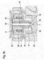
- the section of the fuel injector shown in the region of the solenoid valve 16 according to the invention Fig. 2 Unlike the injector Fig. 1a and 1b a arranged in the low pressure region 6 force or pressure sensor 4 for Nadelsch thoroughlyzeitticianerkennung on.
- the anchor bolt 15 is also supported indirectly via a force distribution plate 17 on the force or pressure sensor 4.
- a change in the pressure in the control chamber 7 causes when the solenoid valve 16 is closed, a change in the force acting on the anchor bolt 15 and thus on the force or pressure sensor 4 axial force F A.
- a biasing member 25 for fixing the position of a magnetic core 31 of the solenoid valve 16 is provided.
- the force or pressure sensor 4 comprises at least one sensor element 5 made of a piezoelectric material with a contact surface 9 or an electrode 10 formed thereon Forming a first ground connection 11 rests against the force distribution plate 17.
- the force distribution plate 17 is in turn electrically connected to the surrounding housing part 12 (see Fig. 3a . 4a and 5a ).
- the biasing member 25 for fixing the position of the magnetic core 31 or the coil 20 and the compression spring 30 is also used in these examples for the axial bias of the force distribution plate 17.
- a bias may be effected via the compression spring 30, the biasing member 25 for the magnetic core 31, an unillustrated additional biasing member, or any combinations thereof.
- the contact surface 9 or the electrode 10 formed thereon bears directly against the force distribution plate 17 for producing a ground connection 11.
- the contact surface 9 opposite contact surface or formed thereon electrode 10 may, however, have no connection to the housing part 12, otherwise the sensor element 5 is electrically short-circuited.
- an electrical insulation 8 is provided between the electrode 10 and the housing part 12.
- the electrical connection of the force or pressure sensor 4 to the injector requires no lines.
- the electrical connection is considerably simplified.
- the electrical contact 13 can also serve the connection with one of the two coil pins of the solenoid valve 16, so that no separate connections between the force or pressure sensor 4 and a control device (not shown) are required. All connections are therefore injector-internal.
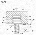
- the Fig. 4a and 4 b shows an embodiment with a force or pressure sensor 4, which includes two sensor elements 5.
- the sensor elements 5 abut one another in such a way that the contact surfaces 9 of the same polarity or the electrodes 10 formed thereon lie opposite one another.
- the targeted contacting 13 takes place in the region of a center electrode 33, which is arranged between the two mutually facing electrodes 10.
- the polarization 18 of the two sensor elements 5 is shown by means of an arrow (see Fig. 4b ).
- the sensor element 5 may also have a multilayer structure, wherein the first layer 5.1 the first sensor element 5 and the second layer 5.2 the second sensor element 5 according to the exemplary embodiment of FIG Fig. 4b replaced.
- the two mutually facing electrodes 10 then merge into an electrode 10 which is integral with the sensor element 5 and is connected to a signal line 14 via a targeted contacting 13.
- the force or pressure sensor of the embodiment of Fig. 5a and 5b comprises a sensor element 5, which consists of two oppositely polarized piezoelectric layers 5. 1, 5.2. In the contact region of both layers 5.1, 5.2, a first internal electrode is formed. Two more outboard Electrodes are formed over the voltage applied to the contact surfaces 9 surfaces of the force distribution plate 17 and the housing part 12, so that a separate formation of electrodes 10 on the Stirnflcähen the sensor element 5 is dispensable.
- the outwardly facing contact surface 9 of the first layer 5.1 is for this purpose directly on the housing part 12 and the corresponding contact surface 9 of the second layer 5.2 directly to the force distribution plate 17 at. Lines for electrical connection of the sensor element 5 are thus unnecessary.
- only the targeted contacting 13 is required in order to connect the sensor element 5 to the signal line 14. The contacting and isolation effort can thus be reduced to a minimum.
Landscapes
- Engineering & Computer Science (AREA)
- Chemical & Material Sciences (AREA)
- Combustion & Propulsion (AREA)
- Mechanical Engineering (AREA)
- General Engineering & Computer Science (AREA)
- Analytical Chemistry (AREA)
- Physics & Mathematics (AREA)
- Fluid Mechanics (AREA)
- Fuel-Injection Apparatus (AREA)
Description
- Die Erfindung betrifft einen Kraftstoffinjektor für ein Kraftstoffeinspritzsystem, insbesondere ein Common-Rail-Einspritzsystem, zum Einspritzen von Kraftstoff in den Brennraum einer Brennkraftmaschine mit den Merkmalen des Oberbegriffs des Anspruchs 1.
- Kraftstoffinjektoren der vorstehend genannten Art weisen eine in einer Hochdruckbohrung hubbeweglich geführte Düsennadel auf, über deren Hubbewegung wenigstens eine Einspritzöffnung freigebbar und verschließbar ist. Der Öffnungshub der Düsennadel wird über eine Entlastung eines Steuerraums bewirkt, in dem ein Steuerdruck anliegt, der die Düsennadel mit einer in Schließrichtung wirkenden Kraft beaufschlagt. Die eingespritzte Kraftstoffmenge hängt dabei vom Einspritzdruck sowie der Öffnungsdauer der Düsennadel ab. Aufgrund von Verschleiß kann sich das Betriebsverhalten des Kraftstoffinjektors jedoch über die Lebensdauer verändern, so dass es die Ansteuerparameter anzupassen gilt.
- Aus der Offenlegungsschrift
DE 10 2007 063 103 A1 ist eine Vorrichtung zur Ermittlung eines Betriebsverhaltens eines Einspritzventils einer Einspritzanlage einer Brennkraftmaschine bekannt, welche einen Piezofoliensensor umfasst, der zur Ermittlung des Schließzeitpunktes des Einspritzventils in das Einspritzventil einsetzbar ist. Mittels des Piezofoliensensors wird vorteilhafterweise das Anschlagen der Ventilnadel am Ventilsitz ermittelt. Auf diese Weise kann erfasst werden, ob ein vorhergesagter Zeitpunkt dem tatsächlichen Zeitpunkt des Anschlages der Ventilnadel am Ventilsitz entspricht. Wird eine Abweichung erkannt, können die Ansteuerparameter einer Ansteuervorrichtung der Einspritzanlage entsprechend angepasst werden. Das Anschlagen der Ventilnadel am Ventilsitz wird vorzugsweise durch eine äußere Krafteinwirkung auf den Piezofoliensensor erkannt. Die äußere Krafteinwirkung bewirkt eine Verformung und damit einhergehend eine Änderung der Ladungsdichte des Piezomaterials, so dass eine zwischen zwei an dem Piezomaterial angeordneten Elektroden erzeugte Spannung als Signal abgreifbar ist. Da der Piezofoliensensor zur Signalgenerierung keine Speisespannung benötigt und die Signale demnach direkt auch ohne Ladungsverstärker abgegriffen werden können, bedarf es zum Abgreifen des Signals lediglich einer Masse- und einer Signalleitung. Das Signal wird dann bevorzugt an eine mit dem Piezofoliensensor verbundene Auswerteeinheit weitergeleitet. - Die
DE102009002895 A1 offenbart einen Kraftstoffinjektor mit einem Kraft- oder Drucksensor der durch einen hubbeweglichen Ankerbolzen mit einer Axialkraft beauschlagbar ist, die proportional zu einem Steuerraumdruck ist. - Ausgehend von dem vorstehend genannten Stand der Technik liegt der Erfindung die Aufgabe zugrunde, einen Kraftstoffinjektor mit einem Kraft- oder Drucksensor zur Bestimmung des Nadelschließzeitpunktes bereitzustellen, der einfach aufgebaut und kostengünstig herstellbar ist. Insbesondere soll der Kraftstoffinjektor eine aufwandsarme elektrische Anbindung des Kraft- oder Drucksensors aufweisen.
- Die Aufgabe wird gelöst durch einen Kraftstoffinjektor mit den Merkmalen des Anspruchs 1. Vorteilhafte Weiterbildungen der Erfindung sind in den Unteransprüchen angegeben.
- Der vorgeschlagene Kraftstoffinjektor umfasst eine in einer Hochdruckbohrung des Kraftstoffinjektors hubbeweglich geführte Düsennadel, über deren Hubbewegung wenigstens eine Einspritzöffnung freigebbar und verschließbar ist, sowie einen Kraft- oder Drucksensor mit wenigstens einem Sensorelement aus einem piezoelektrischen Material zum Erfassen charakteristischer Druckänderungen beim Öffnen und Schließen der Düsennadel. Erfindungsgemäß ist der Kraft- oder Drucksensor in einem Niederdruckbereich des Kraftstoffinjektors angeordnet und beim Öffnen und Schließen der Düsennadel unmittelbar oder mittelbar mit einer Axialkraft FA beaufschlagbar, die proportional zum Steuerraumdruck in einem Steuerraum ist. Das Sensorelement des Kraft- oder Drucksensors ist ferner über wenigstens eine Kontaktfläche oder eine hierauf ausgebildete Elektrode zur Herstellung einer Masseverbindung unmittelbar oder mittelbar mit einem Gehäuseteil des Kraftstoffinjektors elektrisch verbunden.
- Durch die Anordnung des Kraft- oder Drucksensors im Niederdruckbereich wird die Belastung des Sensors verringert, da er nicht dem unter hohen Druck stehenden Kraftstoff ausgesetzt ist. Mit der geringeren Belastung sinken auch die Anforderungen an die Abdichtung der Sensoranordnung gegenüber dem kraftstoffführenden Bereich. Die darüber hinaus vorgeschlagene elektrische Anbindung vereinfacht die Herstellung einer Masseverbindung. Die Masseverbindung wird automatisch durch Auflegen des Sensorelementes auf das Massepotenzial, vorzugsweise ein Gehäuseteil oder ein mit einem Gehäuseteil verbundenes Bauteil des Kraftstoffinjektors hergestellt. Eine gezielte Kontaktierung und/oder die Anbindung an eine Leitung ist nicht erforderlich. Somit ist auch eine Leitungsführung durch den Injektor weitgehend entbehrlich. Sofern das Sensorelement des Kraft- oder Drucksensors nicht unmittelbar am als Massepotenzial dienenden Gehäuseteil des Injektors anliegt, sondern an einem mit dem Gehäuseteil verbundenen weiteren Bauteil, besteht dieses aus einem elektrisch leitenden Material. Die Anbindung kann über eine Kontaktfläche des Sensorelementes oder eine hierauf ausgebildete Elektrode erfolgen, wobei die Elektrode die Kontaktfläche vorzugsweise vollständig bedeckt. Die Elektrode kann beispielsweise in Form einer Beschichtung ausgebildet sein. Die Elektrode bildet dann die eigentliche Kontaktfläche zum Massepotenzial aus. Vorzugsweise ist die Kontaktfläche bzw. die als Kontaktfläche dienende Elektrode an einer der Düsennadel zugewandten Stirnfläche des Sensorelementes ausgebildet, um Leitungsführungen tief in den Injektor hinein zu vermeiden.
- Gemäß einer bevorzugten Ausführungsform der Erfindung ist vorgesehen, dass das Sensorelement über eine gezielte Kontaktierung an eine Signalleitung angeschlossen ist. Die gezielte Kontaktierung erfolgt vorzugsweise im Bereich einer elektrischen Isolierung, welche das Sensorelement gegenüber der Umgebung elektrisch isoliert. Die in den Injektor führenden Leitungen sind dann vorzugsweise auf diese eine Signalleitung beschränkt.
- Gemäß einer weiteren bevorzugten Ausführungsform der Erfindung umfasst der Kraft- oder Drucksensor wenigstens zwei Sensorelemente, die vorzugsweise derart aneinandergesetzt sind, dass sich Kontaktflächen gleicher Polarisierung gegenüber liegen. Die Kontaktflächen können wiederum Elektroden aufweisen, die es dann voneinander elektrisch zu isolieren gilt. Die elektrische Isolation kann jedoch entfallen, wenn die Kontaktflächen gleicher Polarisierung direkt aufeinander liegen und auf diese Weise zu einer Elektrode verschmelzen. Das zweite Sensorelement ist vorzugsweise entsprechend dem ersten Sensorelement ausgebildet und weist eine dem Gehäuseteil zugewandte Kontaktfläche oder eine hierauf ausgebildete Elektrode zur Herstellung einer Masseverbindung auf. Dies ermöglicht eine beidseitige Masseverbindung des zwei Sensorelemente umfassenden Kraft- oder Drucksensors, welche eine aufwendige elektrische Isolation der Sensorelemente gegenüber der Umgebung entbehrlich macht. Das Zusammenschalten zweier Sensorelemente weist zudem den Vorteil auf, dass die Empfindlichkeit des Sensors vergrößert wird.
- Gemäß einer alternativen Ausführungsform der Erfindung ist das Sensorelement mehrschichtig aufgebaut und umfasst wenigstens eine erste und eine zweite Schicht, die vorzugsweise entgegengesetzt polarisiert sind. Das heißt, dass sich im Kontaktbereich beiden Schichten Kontaktflächen gleicher Polarisierung gegenüber liegen. Die mehrschichtige Ausbildung vereinfacht die Herstellung des Kraft- oder Drucksensors, da es keiner Verbindung mehr der einzelnen Sensorelemente bedarf. Zudem entfällt eine elektrische Isolation zwischen den Sensorelementen vollständig.
- Weiterhin wird vorgeschlagen, dass bei Ausführungsformen mit mehr als einem Sensorelement und/oder mit einem mehrschichtigen Sensorelement die gezielte Kontaktierung für den Anschluss an die Signalleitung im Kontaktbereich zweier Sensorelemente bzw. im Kontaktbereich zweier Schichten erfolgt. Dadurch können die Leitungswege für die Signalleitung verkürzt werden.
- Erfindungsgemäß ist der Kraft- oder Drucksensor über einen hubbeweglichen Ankerbolzen eines Magnetventils, das der Ansteuerung der Düsennadel dient, mittelbar über eine Kraftverteilungsplatte mit der Axialkraft FA beaufschlagbar, die proportional zum Steuerraumdruck im Steuerraum ist. Der Ankerbolzen ist dabei an seiner unteren Stirnfläche mit dem Ventilraumdruck beaufschlagt, der bei geschlossenem Magnetventil dem Steuerraumdruck entspricht. Die Düsennadel ist gekoppelt, so dass die Hubbewegung der Düsennadel eine Hubbewegung des Ankerbolzens bewirkt. Um die vom Ankerbolzen auf den Kraft- oder Drucksensor ausgeübte Axialkraft mit weitgehend homogener Flächenpressung in das Sensorelement einzuleiten, ist zwischen dem Kraft- oder Drucksensor und dem Ankerbolzen eine Kraftverteilungsplatte angeordnet. Auf diese Weise wird der Kraft- oder Drucksensor im interessierenden Zeitraum mit der Kraft pst * π * d2/4 vorgespannt, wobei pst der Steuerdruck im Steuerraum und d der Durchmesser des Ankerbolzens ist. Da der Steuerdruck im Zeitpunkt des Nadelschließens ein signifikantes Minimum aufweist, wird auch das vom Kraft- oder Drucksensor ausgegebene Signal ein signifikantes Merkmal aufweisen.
- Gemäß einer Weiterbildung ist die Kraftverteilungsplatte zur Einleitung der Axialkraft FA in den Kraft- oder Drucksensor mittels eines Vorspannelementes gegen den Kraft- oder Drucksensor axial vorgespannt. Dadurch kann eine ungewollte Lageveränderung der Kraftverteilungsplatte verhindert werden.
- Durch die vorstehend beschriebenen Maßnahmen allein oder in beliebiger Kombination kann die elektrische Anbindung des Kraft- oder Ducksensors an den Injektor deutlich vereinfacht werden. Der Injektor mit Nadelschließzeitpunkterkennung ist somit einfach und kostengünstig herstellbar.
- Bevorzugte Ausführungsformen der Erfindung werden nachfolgend anhand der Zeichnungen näher erläutert. Diese zeigen:
-
Fig. 1a einen Längsschnitt durch einen aus dem Stand der Technik bekannten Kraftstoffinjektor, -
Fig. 1b einen Längsschnitt durch das Steuerventil des Kraftstoffinjektors derFig. 1a , -
Fig. 2 einen Längsschnitt durch einen erfindungsgemäßen Kraftstoffinjektor im Bereich des als Magnetventil ausgebildeten Steuerventils, -
Fig. 3a, b jeweils einen Längsschnitt durch einen ersten erfindungsgemäßen Kraft- oder Drucksensor, -
Fig. 4a ,b jeweils einen Längsschnitt durch einen zweiten erfindungsgemäßen Kraft- oder Drucksensor, -
Fig. 4c einen Längsschnitt durch eine Abwandlung der Ausführungsform derFig. 4a ,b und -
Fig. 5a, b jeweils einen Längsschnitt durch einen dritten erfindungsgemäßen Kraft- oder Drucksensor. - Der in den
Fig. 1a und1b dargestellte bekannte Kraftstoffinjektor weist eine in einer Hochdruckbohrung 1 eines Düsenkörpers 21 hubbeweglich geführte Düsennadel 2 auf, welche über einen Ventilkolben 27 mit einer Schließkraft beaufschlagbar ist. Der Ventilkolben 27 ist mit seinem der Düsennadel 2 abgewandten Ende in einem Ventilstück 26 aufgenommen und dort hubbeweglich geführt. Das Ventilstück 26 ist wiederum in einem Injektorkörper 22 aufgenommen. Innerhalb des Ventilstücks 26 wird durch den Ventilkolben 27 ein Steuerraum 7 begrenzt, in welchem ein hydraulischer Druck herrscht, welcher den Ventilkolben 27 und die Düsennadel 2 mit einer in Schließrichtung wirkenden Kraft beaufschlagt. Der Steuerraum 7 ist über eine Zulaufdrossel 28 mit einer KraftstoffZufuhrleitung 23 und über eine Ablaufdrossel 29 mit einem Niederdruckbereich 6 verbindbar, so dass der hydraulische Druck und die Ventilkolbenbewegung in Abhängigkeit von der Schaltstellung des Magnetventils 16 veränderbar sind. Der über die Zufuhrleitung 23 zugeführte unter hohem Druck stehende Kraftstoff wird einem Hochdruckspeicher 24 entnommen. Über die im Düsenkörper 21 ausgebildete Hochdruckbohrung 1 wird der Kraftstoff dann bei geöffneter Düsennadel 2 wenigstens einer Einspritzöffnung 3 zugeführt. - Das in der
Fig. 1b näher dargestellte Magnetventil 16 des Injektors derFig. 1a weist einen mit einer Spule 20 zusammenwirkenden hubbeweglichen Anker 19 sowie einen hierin zumindest teilweise aufgenommenen Ankerbolzen 15 auf. Der Ankerbolzen 15 wird an seiner unteren Stirnfläche mit einem in einem Ventilraum 32 herrschenden Druck beaufschlagt. Dieser Druck entspricht im geschlossenen Zustand des Magnetventils 16 dem Druck im Steuerraum 7. Mit seiner oberen Stirnfläche ist der Ankerbolzen 15 an einem Gehäuseteil 12 des Injektors abgestützt. Im Ruhezustand (unbestromt) wird der Anker 19 durch eine Druckfeder 30 gegen seinen Ventilsitz 34 gedrückt. - Der ausschnittsweise im Bereich des Magnetventils 16 dargestellte erfindungsgemäße Kraftstoffinjektor der
Fig. 2 weist im Unterschied zum Injektor derFig. 1a und1b einen im Niederdruckbereich 6 angeordneten Kraft- oder Drucksensor 4 zur Nadelschließzeitpunkterkennung auf. Anstelle am Gehäuseteil 12 ist der Ankerbolzen 15 zudem mittelbar über eine Kraftverteilungsplatte 17 am Kraft- oder Drucksensor 4 abgestützt. Eine Änderung des Drucks im Steuerraum 7 bewirkt bei geschlossenem Magnetventil 16 eine Änderung der auf den Ankerbolzen 15 und damit auf den Kraft- oder Drucksensor 4 wirkenden Axialkraft FA. Ferner ist ein Vorspannelement 25 zur Lagefixierung eines Magnetkerns 31 des Magnetventils 16 vorgesehen. - Wie den
Fig. 3a, b ,4a-c und5a, b zu entnehmen ist, welche bevorzugte Ausführungsbeispiele eines erfindungsgemäßen Kraftstoffinjektors bzw. eines hierin angeordneten Kraft- oder Drucksensors 4 zeigen, umfasst der Kraft- oder Drucksensor 4 wenigstens ein Sensorelement 5 aus einem piezoelektrischen Material, das mit einer Kontaktfläche 9 oder einer hierauf ausgebildeten Elektrode 10 zur Ausbildung einer ersten Masseverbindung 11 an der Kraftverteilungsplatte 17 anliegt. Die Kraftverteilungsplatte 17 ist wiederum mit dem umgebenden Gehäuseteil 12 elektrisch verbunden (sieheFig. 3a ,4a und5a ). Das Vorspannelement 25 zur Lagefixierung des Magnetkerns 31 bzw. der Spule 20 und der Druckfeder 30 wird in diesen Beispielen zudem zur axialen Vorspannung der Kraftverteilungsplatte 17 eingesetzt. Dies ist aber nicht zwingender Bestandteil der Erfindung. Eine Vorspannung kann über die Druckfeder 30, das Vorspannelement 25 für den Magnetkern 31, ein nicht dargestelltes zusätzliches Vorspannelement oder beliebige Kombinationen hieraus bewirkt werden. Alternativ kann auf eine Vorspannung der Kraftverteilungsplatte 17 aucuh verzichtet werden. - Bei dem Ausführungsbeispiel der
Fig. 3a und 3b umfasst der Kraft- oder Drucksensor 4 lediglich ein Sensorelement 5. Bei nur einem Sensorelement 5 liegt die Kontaktfläche 9 bzw. die hierauf ausgebildete Elektrode 10 direkt an der Kraftverteilungsplatte 17 zur Herstellung einer Masseverbindung 11 an. Die der Kontaktfläche 9 gegenüberliegende Kontaktfläche bzw. hierauf ausgebildete Elektrode 10 darf dagegen keine Verbindung zum Gehäuseteil 12 aufweisen, da sonst das Sensorelement 5 elektrisch kurzgeschlossen ist. Um dies zu verhindern, ist zwischen der Elektrode 10 und dem Gehäuseteil 12 eine elektrische Isolierung 8 vorgesehen. Der Anschluss an eine Signalleitung 14 erfolgt über eine gezielte Kontaktierung 13 im Bereich der elektrischen Isolierung 8. Bis auf die Signalleitung 14 erfordert die elektrische Anbindung des Kraft- oder Drucksensors 4 an den Injektor keine Leitungen. Die elektrische Anbindung wird dadurch erheblich vereinfacht. Die elektrische Kontaktierung 13 kann auch der Verbindung mit einem der beiden Spulenpins des Magnetventils 16 dienen, so dass keine separaten Verbindungen zwischen dem Kraft- oder Drucksensor 4 und einem Steuergerät (nicht dargestellt) erforderlich sind. Sämtliche Anschlüsse erfolgen demnach injektorintern. - Den
Fig. 4a und4 b ist ein Ausführungsbeispiel mit einem Kraft- oder Drucksensor 4 zu entnehmen, welcher zwei Sensorelemente 5 umfasst. Die Sensorelemente 5 liegen derart aneinander an, dass die Kontaktflächen 9 gleicher Polarität bzw. die hierauf ausgebildeten Elektroden 10 einander gegenüber liegen. Die gezielte Kontaktierung 13 erfolgt im Bereich einer Mittelelektrode 33, welche zwischen den beiden einander zugewandten Elektroden 10 angeordnet ist. Die Polarisierung 18 der beiden Sensorelemente 5 ist mit Hilfe eines Pfeils dargestellt (sieheFig. 4b ). - Um den Herstellungsaufwand zu verringern, wird gemäß einer Weiterbildung (nicht dargestellt) vorgeschlagen, dass auf die Ausbildung innenliegender Elektroden 10 verzichtet wird. Die beiden Sensorelemente 5 werden stattdessen mit ihren Kontaktflächen 9 auf die Mittelelektrode 33 gelegt, welche dann die Funktion der beiden einander zugewandten Elektroden 10 mit übernimmt.
- Alternativ kann - wie in der
Fig. 4c dargestellt - das Sensorelement 5 auch mehrschichtig aufgebaut sein, wobei die erste Schicht 5.1 das erste Sensorelement 5 und die zweite Schicht 5.2 das zweite Sensorelement 5 gemäß dem Ausführungsbeispiel derFig. 4b ersetzt. Die beiden einander zugewandten Elektroden 10 verschmelzen dann zu einer integral zum Sensorelement 5 gehörenden mittig liegenden Elektrode 10. Über eine gezielte Kontaktierung 13 erfolgt der Anschluss an eine Signalleitung 14. - Der Kraft- oder Drucksensor des Ausführungsbeispiels der
Fig. 5a und 5b umfasst ein Sensorelement 5, das aus zwei entgegengesetzt polarisierten piezoelektrischen Schichten 5. 1, 5.2 besteht. Im Kontaktbereich beider Schichten 5.1, 5.2 wird eine erste innenliegende Elektrode ausgebildet. Zwei weitere außenliegende Elektroden werden über die an den Kontaktflächen 9 anliegenden Oberflächen der Kraftverteilungsplatte 17 und des Gehäuseteils 12 ausgebildet, so dass eine separate Ausbildung von Elektroden 10 an den Stirnflcähen des Sensorelementes 5 verzichtbar ist. Die nach außen gewandte Kontaktfläche 9 der ersten Schicht 5.1 liegt hierzu direkt am Gehäuseteil 12 und die entsprechende Kontaktfläche 9 der zweiten Schicht 5.2 direkt an der Kraftverteilungsplatte 17 an. Leitungen zur elektrischen Anbindung des Sensorelementes 5 sind somit entbehrlich. Es bedarf darüber hinaus nur der gezielten Kontaktierung 13, um das Sensorelement 5 an die Signalleitung 14 anzuschließen. Der Kontaktierungs- und Isolationsaufwand kann somit auf ein Minimum reduziert werden.
Claims (6)
- Kraftstoffinjektor für ein Kraftstoffeinspritzsystem, insbesondere ein Common-Rail-Einspritzsystem, umfassend eine in einer Hochdruckbohrung (1) des Kraftstoffinjektors hubbeweglich geführte Düsennadel (2), über deren Hubbewegung wenigstens eine Einspritzöffnung (3) freigebbar und verschließbar ist, sowie einen Kraft- oder Drucksensor (4) mit wenigstens einem Sensorelement (5) aus einem piezoelektrischen Material zum Erfassen charakteristischer Druckänderungen beim Öffnen und Schließen der Düsennadel (2), wobei der Kraft- oder Drucksensor (4) in einem Niederdruckbereich (6) des Kraftstoffinjektors angeordnet ist und beim Öffnen und Schließen der Düsennadel (2) mittelbar über einen hubbeweglichen Ankerbolzen (15) eines Magnetventils (16), das der Ansteuerung der Düsennadel (2) dient, und eine Kraftverteilungsplatte (17) mit einer Axialkraft (FA) beaufschlagbar ist, die proportional zum Steuerraumdruck in einem Steuerraum (7) ist, wobei der Steuerraumdruck die Düsennadel (2) mit einer in Schließrichtung wirkenden Kraft beaufschlagt, und, dass das Sensorelement (5) des Kraft- oder Drucksensors (4) über wenigstens eine Kontaktfläche (9) oder eine hierauf ausgebildete Elektrode (10) zur Herstellung einer Masseverbindung (11) unmittelbar oder mittelbar mit einem Gehäuseteil (12) des Kraftstoffinjektors elektrisch verbunden ist, und das Magnetventil (16) einen mit einer Spule (20) zusammenwirkenden hubbeweglichen Anker (19) umfasst, der durch die Druckfeder (30) gegen einen Ventilsitz (34) gedrückt wird und der den Ankerbolzen (15) zumindest teilweise aufnimmt, wobei die Druckfeder (30) die Kraftverteilungsplatte (17) gegen den Kraft- oder Drucksensor (4) axial vorspannt
- Kraftstoffinjektor nach Anspruch 1,
dadurch gekennzeichnet, dass das Sensorelement (5) über eine gezielte Kontaktierung (13), vorzugsweise im Bereich einer elektrischen Isolierung (8), an eine Signalleitung (14) angeschlossen ist. - Kraftstoffinjektor nach Anspruch 1 oder 2,
dadurch gekennzeichnet, dass der Kraft- oder Drucksensor (4) wenigstens zwei Sensorelemente (5) umfasst, die vorzugsweise derart aneinandergesetzt sind, dass sich Kontaktflächen gleicher Polarisierung (18) gegenüber liegen. - Kraftstoffinjektor nach einem der vorhergehenden Ansprüche,
dadurch gekennzeichnet, dass das Sensorelement (5) mehrschichtig aufgebaut ist und wenigstens eine erste und eine zweite Schicht (5.1, 5.2) umfasst, die vorzugsweise entgegengesetzt polarisiert sind. - Kraftstoffinjektor nach einem der Ansprüche 2 bis 4,
dadurch gekennzeichnet, dass die gezielte Kontaktierung (13) für den Anschluss an die Signalleitung (14) im Kontaktbereich zweier Sensorelemente (5) oder im Kontaktbereich zweier Schichten (5.1, 5.2) erfolgt. - Kraftstoffinjektor nach Anspruch 1,
dadurch gekennzeichnet, dass die Kraftverteilungsplatte (17) zusätzlich mittels eines Vorspannelementes (25) gegen den Kraft- oder Drucksensor (4) axial vorgespannt ist.
Applications Claiming Priority (3)
| Application Number | Priority Date | Filing Date | Title |
|---|---|---|---|
| DE102011006975 | 2011-04-07 | ||
| DE102011078947A DE102011078947A1 (de) | 2011-04-07 | 2011-07-11 | Kraftstoffinjektor |
| PCT/EP2012/052990 WO2012136406A1 (de) | 2011-04-07 | 2012-02-22 | Kraftstoffinjektor |
Publications (2)
| Publication Number | Publication Date |
|---|---|
| EP2694794A1 EP2694794A1 (de) | 2014-02-12 |
| EP2694794B1 true EP2694794B1 (de) | 2019-04-24 |
Family
ID=46875237
Family Applications (2)
| Application Number | Title | Priority Date | Filing Date |
|---|---|---|---|
| EP12706532.4A Active EP2694794B1 (de) | 2011-04-07 | 2012-02-22 | Kraftstoffinjektor |
| EP12714655.3A Active EP2694795B1 (de) | 2011-04-07 | 2012-04-05 | Kraftstoffinjektor |
Family Applications After (1)
| Application Number | Title | Priority Date | Filing Date |
|---|---|---|---|
| EP12714655.3A Active EP2694795B1 (de) | 2011-04-07 | 2012-04-05 | Kraftstoffinjektor |
Country Status (6)
| Country | Link |
|---|---|
| US (1) | US20140027534A1 (de) |
| EP (2) | EP2694794B1 (de) |
| JP (1) | JP6265884B2 (de) |
| CN (2) | CN103477063B (de) |
| DE (2) | DE102011078953A1 (de) |
| WO (2) | WO2012136406A1 (de) |
Families Citing this family (13)
| Publication number | Priority date | Publication date | Assignee | Title |
|---|---|---|---|---|
| DE102012223244A1 (de) * | 2012-12-14 | 2014-06-18 | Robert Bosch Gmbh | Kraftstoffeinspritzventil für Brennkraftmaschinen |
| DE102013220032A1 (de) * | 2013-10-02 | 2015-04-02 | Robert Bosch Gmbh | Kraftstoffinjektor und Verfahren zum Herstellen eines Kraftstoffinjektors |
| DE102014219973B4 (de) * | 2013-10-04 | 2021-04-29 | Vitesco Technologies GmbH | Kraftstoffhochdruckanordnung |
| DE102014204098A1 (de) * | 2014-03-06 | 2015-09-10 | Robert Bosch Gmbh | Verfahren zur Regelung eines Common-Rail-Injektors |
| GB2530738A (en) * | 2014-09-30 | 2016-04-06 | Gm Global Tech Operations Inc | Method of controlling an injection dwell time between two injections of a fuel injector |
| DE102015217645A1 (de) * | 2015-09-15 | 2017-03-16 | Robert Bosch Gmbh | Verfahren zum Betreiben einer Einspritzanlage |
| DE102015222246A1 (de) | 2015-11-11 | 2017-05-11 | Robert Bosch Gmbh | Prüfvorrichtung für die Dauerprüfung von Kraftsensoren |
| CN107387283B (zh) * | 2017-08-28 | 2023-08-11 | 机科发展科技股份有限公司 | 共轨喷油器衬环选配及衔铁升程测量装置 |
| IT201900006429A1 (it) * | 2019-04-29 | 2020-10-29 | Omt Digital S R L | Sensore per la diagnostica non invasiva di sistemi idraulici ad alta pressione, in particolare di sistemi di iniezione di combustibile, e sistema idraulico comprendente tale sensore |
| IT201900006428A1 (it) * | 2019-04-29 | 2020-10-29 | Omt Digital S R L | Procedimento per il monitoraggio di un iniettore common-rail per grandi motori diesel e dual-fuel e iniettore configurato per implementare tale procedimento |
| RU2731155C1 (ru) * | 2019-07-05 | 2020-08-31 | федеральное государственное бюджетное образовательное учреждение высшего образования "Московский политехнический университет" (Московский Политех) | Форсунка с электрогидравлическим управлением |
| DE102021108839A1 (de) | 2021-04-09 | 2022-10-13 | Schaeffler Technologies AG & Co. KG | Drucksensoranordnung für einen hydraulischer Aktor mit einem über eine Federeinrichtung fixierten Drucksensor |
| SE546150C2 (en) * | 2022-04-22 | 2024-06-11 | Scania Cv Ab | Fuel Injector, Internal Combustion Engine, and Vehicle |
Citations (2)
| Publication number | Priority date | Publication date | Assignee | Title |
|---|---|---|---|---|
| US4662564A (en) * | 1984-05-15 | 1987-05-05 | Diesel Kiki Co., Ltd. | Fuel injection nozzle with timing sensor |
| US20070277618A1 (en) * | 2006-06-06 | 2007-12-06 | Dietmar Kroeger | Piezoelectric sensor |
Family Cites Families (20)
| Publication number | Priority date | Publication date | Assignee | Title |
|---|---|---|---|---|
| JPS56113044A (en) * | 1980-02-13 | 1981-09-05 | Nissan Motor Co Ltd | Injection timing sensor |
| JPH0843432A (ja) * | 1994-07-26 | 1996-02-16 | Fuji Ceramics:Kk | 加速度センサ及びその製造方法 |
| JPH08184520A (ja) * | 1994-12-27 | 1996-07-16 | Unisia Jecs Corp | 圧力センサ |
| DE19813756A1 (de) * | 1998-03-27 | 1999-10-07 | Siemens Ag | Messung des Drucks eines Fluids |
| JP2002339793A (ja) * | 2001-05-15 | 2002-11-27 | Nippon Soken Inc | 燃焼圧センサ |
| JP4306144B2 (ja) * | 2001-05-21 | 2009-07-29 | 株式会社デンソー | 燃料噴射弁 |
| US6598591B2 (en) * | 2001-12-18 | 2003-07-29 | Caterpillar Inc | Measuring check motion through pressure sensing |
| EP1486665A4 (de) * | 2002-03-15 | 2010-09-01 | Bosch Automotive Systems Corp | Kraftstoffeinspritzventil |
| JP3873040B2 (ja) * | 2003-06-23 | 2007-01-24 | シチズンファインテック株式会社 | 圧力センサ |
| JP4308697B2 (ja) * | 2004-03-31 | 2009-08-05 | 本田技研工業株式会社 | 筒内圧検出装置 |
| JP4134979B2 (ja) * | 2004-11-22 | 2008-08-20 | 株式会社デンソー | 内燃機関用燃料噴射装置 |
| DE102005058302A1 (de) * | 2005-12-07 | 2007-06-14 | Robert Bosch Gmbh | Verformungsoptimierte Ankerführung für Magnetventile |
| DE102006055486A1 (de) * | 2006-11-24 | 2008-05-29 | Robert Bosch Gmbh | Kraftstoffeinspritzventil für Brennkraftmaschinen |
| JP4743138B2 (ja) * | 2007-03-05 | 2011-08-10 | 株式会社デンソー | 燃料噴射装置 |
| DE102007063103A1 (de) | 2007-12-28 | 2009-07-02 | Robert Bosch Gmbh | Vorrichtung zur Ermittlung eines Betriebsverhaltens eines Einspritzventils |
| JP2010103315A (ja) * | 2008-10-23 | 2010-05-06 | Denso Corp | 圧電アクチュエータおよびそれを用いた燃料噴射弁 |
| JP5339950B2 (ja) * | 2009-02-16 | 2013-11-13 | 株式会社ミクニ | 燃焼圧センサ付きグロープラグ |
| JP5120316B2 (ja) * | 2009-04-03 | 2013-01-16 | 株式会社デンソー | 燃料噴射装置 |
| DE102009002895A1 (de) * | 2009-05-07 | 2010-11-11 | Robert Bosch Gmbh | Kraftstoffinjektor mit Drucksensor |
| DE102009047611A1 (de) * | 2009-12-08 | 2011-06-09 | Robert Bosch Gmbh | Kraftstoffeinspritzvorrichtung mit Nadelpositionsbestimmung |
-
2011
- 2011-07-11 DE DE102011078953A patent/DE102011078953A1/de not_active Withdrawn
- 2011-07-11 DE DE102011078947A patent/DE102011078947A1/de not_active Withdrawn
-
2012
- 2012-02-22 CN CN201280016215.1A patent/CN103477063B/zh active Active
- 2012-02-22 EP EP12706532.4A patent/EP2694794B1/de active Active
- 2012-02-22 WO PCT/EP2012/052990 patent/WO2012136406A1/de not_active Ceased
- 2012-02-22 JP JP2014503040A patent/JP6265884B2/ja active Active
- 2012-02-22 US US14/110,411 patent/US20140027534A1/en not_active Abandoned
- 2012-04-05 EP EP12714655.3A patent/EP2694795B1/de active Active
- 2012-04-05 CN CN201280016209.6A patent/CN103459820B/zh active Active
- 2012-04-05 WO PCT/EP2012/056286 patent/WO2012136767A1/de not_active Ceased
Patent Citations (2)
| Publication number | Priority date | Publication date | Assignee | Title |
|---|---|---|---|---|
| US4662564A (en) * | 1984-05-15 | 1987-05-05 | Diesel Kiki Co., Ltd. | Fuel injection nozzle with timing sensor |
| US20070277618A1 (en) * | 2006-06-06 | 2007-12-06 | Dietmar Kroeger | Piezoelectric sensor |
Also Published As
| Publication number | Publication date |
|---|---|
| CN103477063A (zh) | 2013-12-25 |
| JP6265884B2 (ja) | 2018-01-24 |
| CN103477063B (zh) | 2018-03-13 |
| CN103459820A (zh) | 2013-12-18 |
| WO2012136767A1 (de) | 2012-10-11 |
| EP2694794A1 (de) | 2014-02-12 |
| US20140027534A1 (en) | 2014-01-30 |
| WO2012136406A1 (de) | 2012-10-11 |
| CN103459820B (zh) | 2017-02-15 |
| DE102011078947A1 (de) | 2012-10-11 |
| DE102011078953A1 (de) | 2012-10-11 |
| JP2014510233A (ja) | 2014-04-24 |
| EP2694795B1 (de) | 2015-07-01 |
| EP2694795A1 (de) | 2014-02-12 |
Similar Documents
| Publication | Publication Date | Title |
|---|---|---|
| WO2012136406A1 (de) | Kraftstoffinjektor | |
| EP2640955B1 (de) | Kraftstoffinjektor | |
| DE102010016298A1 (de) | Kraftstoffeinspritzvorrichtung mit Kraftstoffdrucksensor und Verfahren zu ihrer elektrischen Verbindung | |
| EP2428672A2 (de) | Kraftstoffinjektor | |
| WO2013185996A1 (de) | Verfahren zum betreiben eines ventils | |
| DE102004015745A1 (de) | Einrichtung zum Einspritzen von Kraftstoff in den Brennraum einer Brennkraftmaschine mit einem Nadelhubsensor | |
| WO2010136302A1 (de) | Druckregelventil, insbesondere für einen hochdruckspeicherkörper eines kraftstoffeinspritzsystems | |
| EP2427649A1 (de) | Vorrichtung zum einspritzen von kraftstoff | |
| EP2417346B1 (de) | Piezoelektrischer aktor und brennstoffeinspritzventil | |
| EP2813698B1 (de) | Brennstoffeinspritzventil | |
| WO2007118726A1 (de) | Aktormodul | |
| EP2990639B1 (de) | Kraftstoffinjektor | |
| WO2021028349A1 (de) | Sitzplatte für einen injektor und verfahren zum herstellen einer solchen sitzplatte | |
| DE102015208488A1 (de) | Kraftstoffinjektor sowie Vorrichtung und Verfahren zur Montage einer Messeinrichtung | |
| DE102005002796A1 (de) | Ventilvorrichtung | |
| WO2015058930A1 (de) | Kraftstoffinjektor | |
| EP3034854B1 (de) | Kraftstoffinjektor und verfahren zur erkennung zumindest des schliesszeitpunkts eines einspritzglieds | |
| EP3111079A1 (de) | Kraftstoffinjektor | |
| EP1546542B1 (de) | Einspritzventil für die einspritzung von kraftstoff in eine verbrennungskraftmaschine | |
| EP1878907B1 (de) | Brennstoffeinspritzventil | |
| WO2007065745A1 (de) | Niederhaltung einer magnetgruppe in einem brennstoffinjektor | |
| DE19963390A1 (de) | Kraftstoffeinspritzeinrichtung für Brennkraftmaschinen | |
| EP1688612A1 (de) | Brennstoffeinspritzventil | |
| EP2013923A2 (de) | Piezoaktor mit einer ummantelung | |
| EP2299101A1 (de) | Magnetventil mit direkt kontaktierter Steuereinheit |
Legal Events
| Date | Code | Title | Description |
|---|---|---|---|
| PUAI | Public reference made under article 153(3) epc to a published international application that has entered the european phase |
Free format text: ORIGINAL CODE: 0009012 |
|
| 17P | Request for examination filed |
Effective date: 20131107 |
|
| AK | Designated contracting states |
Kind code of ref document: A1 Designated state(s): AL AT BE BG CH CY CZ DE DK EE ES FI FR GB GR HR HU IE IS IT LI LT LU LV MC MK MT NL NO PL PT RO RS SE SI SK SM TR |
|
| DAX | Request for extension of the european patent (deleted) | ||
| 17Q | First examination report despatched |
Effective date: 20150311 |
|
| STAA | Information on the status of an ep patent application or granted ep patent |
Free format text: STATUS: EXAMINATION IS IN PROGRESS |
|
| GRAP | Despatch of communication of intention to grant a patent |
Free format text: ORIGINAL CODE: EPIDOSNIGR1 |
|
| STAA | Information on the status of an ep patent application or granted ep patent |
Free format text: STATUS: GRANT OF PATENT IS INTENDED |
|
| INTG | Intention to grant announced |
Effective date: 20181114 |
|
| GRAS | Grant fee paid |
Free format text: ORIGINAL CODE: EPIDOSNIGR3 |
|
| GRAA | (expected) grant |
Free format text: ORIGINAL CODE: 0009210 |
|
| STAA | Information on the status of an ep patent application or granted ep patent |
Free format text: STATUS: THE PATENT HAS BEEN GRANTED |
|
| AK | Designated contracting states |
Kind code of ref document: B1 Designated state(s): AL AT BE BG CH CY CZ DE DK EE ES FI FR GB GR HR HU IE IS IT LI LT LU LV MC MK MT NL NO PL PT RO RS SE SI SK SM TR |
|
| REG | Reference to a national code |
Ref country code: GB Ref legal event code: FG4D Free format text: NOT ENGLISH |
|
| REG | Reference to a national code |
Ref country code: CH Ref legal event code: EP |
|
| REG | Reference to a national code |
Ref country code: AT Ref legal event code: REF Ref document number: 1124454 Country of ref document: AT Kind code of ref document: T Effective date: 20190515 Ref country code: IE Ref legal event code: FG4D Free format text: LANGUAGE OF EP DOCUMENT: GERMAN |
|
| REG | Reference to a national code |
Ref country code: DE Ref legal event code: R096 Ref document number: 502012014652 Country of ref document: DE |
|
| REG | Reference to a national code |
Ref country code: NL Ref legal event code: MP Effective date: 20190424 |
|
| REG | Reference to a national code |
Ref country code: LT Ref legal event code: MG4D |
|
| PG25 | Lapsed in a contracting state [announced via postgrant information from national office to epo] |
Ref country code: NL Free format text: LAPSE BECAUSE OF FAILURE TO SUBMIT A TRANSLATION OF THE DESCRIPTION OR TO PAY THE FEE WITHIN THE PRESCRIBED TIME-LIMIT Effective date: 20190424 |
|
| PG25 | Lapsed in a contracting state [announced via postgrant information from national office to epo] |
Ref country code: SE Free format text: LAPSE BECAUSE OF FAILURE TO SUBMIT A TRANSLATION OF THE DESCRIPTION OR TO PAY THE FEE WITHIN THE PRESCRIBED TIME-LIMIT Effective date: 20190424 Ref country code: NO Free format text: LAPSE BECAUSE OF FAILURE TO SUBMIT A TRANSLATION OF THE DESCRIPTION OR TO PAY THE FEE WITHIN THE PRESCRIBED TIME-LIMIT Effective date: 20190724 Ref country code: FI Free format text: LAPSE BECAUSE OF FAILURE TO SUBMIT A TRANSLATION OF THE DESCRIPTION OR TO PAY THE FEE WITHIN THE PRESCRIBED TIME-LIMIT Effective date: 20190424 Ref country code: PT Free format text: LAPSE BECAUSE OF FAILURE TO SUBMIT A TRANSLATION OF THE DESCRIPTION OR TO PAY THE FEE WITHIN THE PRESCRIBED TIME-LIMIT Effective date: 20190824 Ref country code: AL Free format text: LAPSE BECAUSE OF FAILURE TO SUBMIT A TRANSLATION OF THE DESCRIPTION OR TO PAY THE FEE WITHIN THE PRESCRIBED TIME-LIMIT Effective date: 20190424 Ref country code: LT Free format text: LAPSE BECAUSE OF FAILURE TO SUBMIT A TRANSLATION OF THE DESCRIPTION OR TO PAY THE FEE WITHIN THE PRESCRIBED TIME-LIMIT Effective date: 20190424 Ref country code: HR Free format text: LAPSE BECAUSE OF FAILURE TO SUBMIT A TRANSLATION OF THE DESCRIPTION OR TO PAY THE FEE WITHIN THE PRESCRIBED TIME-LIMIT Effective date: 20190424 Ref country code: ES Free format text: LAPSE BECAUSE OF FAILURE TO SUBMIT A TRANSLATION OF THE DESCRIPTION OR TO PAY THE FEE WITHIN THE PRESCRIBED TIME-LIMIT Effective date: 20190424 |
|
| PG25 | Lapsed in a contracting state [announced via postgrant information from national office to epo] |
Ref country code: LV Free format text: LAPSE BECAUSE OF FAILURE TO SUBMIT A TRANSLATION OF THE DESCRIPTION OR TO PAY THE FEE WITHIN THE PRESCRIBED TIME-LIMIT Effective date: 20190424 Ref country code: RS Free format text: LAPSE BECAUSE OF FAILURE TO SUBMIT A TRANSLATION OF THE DESCRIPTION OR TO PAY THE FEE WITHIN THE PRESCRIBED TIME-LIMIT Effective date: 20190424 Ref country code: BG Free format text: LAPSE BECAUSE OF FAILURE TO SUBMIT A TRANSLATION OF THE DESCRIPTION OR TO PAY THE FEE WITHIN THE PRESCRIBED TIME-LIMIT Effective date: 20190724 Ref country code: PL Free format text: LAPSE BECAUSE OF FAILURE TO SUBMIT A TRANSLATION OF THE DESCRIPTION OR TO PAY THE FEE WITHIN THE PRESCRIBED TIME-LIMIT Effective date: 20190424 Ref country code: GR Free format text: LAPSE BECAUSE OF FAILURE TO SUBMIT A TRANSLATION OF THE DESCRIPTION OR TO PAY THE FEE WITHIN THE PRESCRIBED TIME-LIMIT Effective date: 20190725 |
|
| PG25 | Lapsed in a contracting state [announced via postgrant information from national office to epo] |
Ref country code: IS Free format text: LAPSE BECAUSE OF FAILURE TO SUBMIT A TRANSLATION OF THE DESCRIPTION OR TO PAY THE FEE WITHIN THE PRESCRIBED TIME-LIMIT Effective date: 20190824 |
|
| REG | Reference to a national code |
Ref country code: DE Ref legal event code: R097 Ref document number: 502012014652 Country of ref document: DE |
|
| PG25 | Lapsed in a contracting state [announced via postgrant information from national office to epo] |
Ref country code: DK Free format text: LAPSE BECAUSE OF FAILURE TO SUBMIT A TRANSLATION OF THE DESCRIPTION OR TO PAY THE FEE WITHIN THE PRESCRIBED TIME-LIMIT Effective date: 20190424 Ref country code: EE Free format text: LAPSE BECAUSE OF FAILURE TO SUBMIT A TRANSLATION OF THE DESCRIPTION OR TO PAY THE FEE WITHIN THE PRESCRIBED TIME-LIMIT Effective date: 20190424 Ref country code: RO Free format text: LAPSE BECAUSE OF FAILURE TO SUBMIT A TRANSLATION OF THE DESCRIPTION OR TO PAY THE FEE WITHIN THE PRESCRIBED TIME-LIMIT Effective date: 20190424 Ref country code: SK Free format text: LAPSE BECAUSE OF FAILURE TO SUBMIT A TRANSLATION OF THE DESCRIPTION OR TO PAY THE FEE WITHIN THE PRESCRIBED TIME-LIMIT Effective date: 20190424 Ref country code: CZ Free format text: LAPSE BECAUSE OF FAILURE TO SUBMIT A TRANSLATION OF THE DESCRIPTION OR TO PAY THE FEE WITHIN THE PRESCRIBED TIME-LIMIT Effective date: 20190424 |
|
| PG25 | Lapsed in a contracting state [announced via postgrant information from national office to epo] |
Ref country code: IT Free format text: LAPSE BECAUSE OF FAILURE TO SUBMIT A TRANSLATION OF THE DESCRIPTION OR TO PAY THE FEE WITHIN THE PRESCRIBED TIME-LIMIT Effective date: 20190424 Ref country code: SM Free format text: LAPSE BECAUSE OF FAILURE TO SUBMIT A TRANSLATION OF THE DESCRIPTION OR TO PAY THE FEE WITHIN THE PRESCRIBED TIME-LIMIT Effective date: 20190424 |
|
| PLBE | No opposition filed within time limit |
Free format text: ORIGINAL CODE: 0009261 |
|
| STAA | Information on the status of an ep patent application or granted ep patent |
Free format text: STATUS: NO OPPOSITION FILED WITHIN TIME LIMIT |
|
| PG25 | Lapsed in a contracting state [announced via postgrant information from national office to epo] |
Ref country code: TR Free format text: LAPSE BECAUSE OF FAILURE TO SUBMIT A TRANSLATION OF THE DESCRIPTION OR TO PAY THE FEE WITHIN THE PRESCRIBED TIME-LIMIT Effective date: 20190424 |
|
| 26N | No opposition filed |
Effective date: 20200127 |
|
| PG25 | Lapsed in a contracting state [announced via postgrant information from national office to epo] |
Ref country code: SI Free format text: LAPSE BECAUSE OF FAILURE TO SUBMIT A TRANSLATION OF THE DESCRIPTION OR TO PAY THE FEE WITHIN THE PRESCRIBED TIME-LIMIT Effective date: 20190424 |
|
| REG | Reference to a national code |
Ref country code: CH Ref legal event code: PL |
|
| GBPC | Gb: european patent ceased through non-payment of renewal fee |
Effective date: 20200222 |
|
| REG | Reference to a national code |
Ref country code: BE Ref legal event code: MM Effective date: 20200229 |
|
| PG25 | Lapsed in a contracting state [announced via postgrant information from national office to epo] |
Ref country code: MC Free format text: LAPSE BECAUSE OF FAILURE TO SUBMIT A TRANSLATION OF THE DESCRIPTION OR TO PAY THE FEE WITHIN THE PRESCRIBED TIME-LIMIT Effective date: 20190424 Ref country code: LU Free format text: LAPSE BECAUSE OF NON-PAYMENT OF DUE FEES Effective date: 20200222 |
|
| PG25 | Lapsed in a contracting state [announced via postgrant information from national office to epo] |
Ref country code: LI Free format text: LAPSE BECAUSE OF NON-PAYMENT OF DUE FEES Effective date: 20200229 Ref country code: CH Free format text: LAPSE BECAUSE OF NON-PAYMENT OF DUE FEES Effective date: 20200229 |
|
| PG25 | Lapsed in a contracting state [announced via postgrant information from national office to epo] |
Ref country code: IE Free format text: LAPSE BECAUSE OF NON-PAYMENT OF DUE FEES Effective date: 20200222 Ref country code: GB Free format text: LAPSE BECAUSE OF NON-PAYMENT OF DUE FEES Effective date: 20200222 |
|
| PG25 | Lapsed in a contracting state [announced via postgrant information from national office to epo] |
Ref country code: BE Free format text: LAPSE BECAUSE OF NON-PAYMENT OF DUE FEES Effective date: 20200229 |
|
| REG | Reference to a national code |
Ref country code: AT Ref legal event code: MM01 Ref document number: 1124454 Country of ref document: AT Kind code of ref document: T Effective date: 20200222 |
|
| PG25 | Lapsed in a contracting state [announced via postgrant information from national office to epo] |
Ref country code: AT Free format text: LAPSE BECAUSE OF NON-PAYMENT OF DUE FEES Effective date: 20200222 |
|
| PG25 | Lapsed in a contracting state [announced via postgrant information from national office to epo] |
Ref country code: MT Free format text: LAPSE BECAUSE OF FAILURE TO SUBMIT A TRANSLATION OF THE DESCRIPTION OR TO PAY THE FEE WITHIN THE PRESCRIBED TIME-LIMIT Effective date: 20190424 Ref country code: CY Free format text: LAPSE BECAUSE OF FAILURE TO SUBMIT A TRANSLATION OF THE DESCRIPTION OR TO PAY THE FEE WITHIN THE PRESCRIBED TIME-LIMIT Effective date: 20190424 |
|
| PG25 | Lapsed in a contracting state [announced via postgrant information from national office to epo] |
Ref country code: MK Free format text: LAPSE BECAUSE OF FAILURE TO SUBMIT A TRANSLATION OF THE DESCRIPTION OR TO PAY THE FEE WITHIN THE PRESCRIBED TIME-LIMIT Effective date: 20190424 |
|
| PGFP | Annual fee paid to national office [announced via postgrant information from national office to epo] |
Ref country code: DE Payment date: 20250422 Year of fee payment: 14 |
|
| PGFP | Annual fee paid to national office [announced via postgrant information from national office to epo] |
Ref country code: FR Payment date: 20260223 Year of fee payment: 15 |