EP2687816B1 - Shape measuring apparatus and control method of shape measuring apparatus - Google Patents
Shape measuring apparatus and control method of shape measuring apparatus Download PDFInfo
- Publication number
- EP2687816B1 EP2687816B1 EP13176698.2A EP13176698A EP2687816B1 EP 2687816 B1 EP2687816 B1 EP 2687816B1 EP 13176698 A EP13176698 A EP 13176698A EP 2687816 B1 EP2687816 B1 EP 2687816B1
- Authority
- EP
- European Patent Office
- Prior art keywords
- speed
- measurement target
- target section
- movement
- measuring apparatus
- Prior art date
- Legal status (The legal status is an assumption and is not a legal conclusion. Google has not performed a legal analysis and makes no representation as to the accuracy of the status listed.)
- Active
Links
Images


Classifications
-
- G—PHYSICS
- G01—MEASURING; TESTING
- G01B—MEASURING LENGTH, THICKNESS OR SIMILAR LINEAR DIMENSIONS; MEASURING ANGLES; MEASURING AREAS; MEASURING IRREGULARITIES OF SURFACES OR CONTOURS
- G01B5/00—Measuring arrangements characterised by the use of mechanical techniques
- G01B5/004—Measuring arrangements characterised by the use of mechanical techniques for measuring coordinates of points
- G01B5/008—Measuring arrangements characterised by the use of mechanical techniques for measuring coordinates of points using coordinate measuring machines
-
- G—PHYSICS
- G01—MEASURING; TESTING
- G01B—MEASURING LENGTH, THICKNESS OR SIMILAR LINEAR DIMENSIONS; MEASURING ANGLES; MEASURING AREAS; MEASURING IRREGULARITIES OF SURFACES OR CONTOURS
- G01B21/00—Measuring arrangements or details thereof, where the measuring technique is not covered by the other groups of this subclass, unspecified or not relevant
- G01B21/02—Measuring arrangements or details thereof, where the measuring technique is not covered by the other groups of this subclass, unspecified or not relevant for measuring length, width, or thickness
- G01B21/04—Measuring arrangements or details thereof, where the measuring technique is not covered by the other groups of this subclass, unspecified or not relevant for measuring length, width, or thickness by measuring coordinates of points
- G01B21/042—Calibration or calibration artifacts
-
- G—PHYSICS
- G01—MEASURING; TESTING
- G01B—MEASURING LENGTH, THICKNESS OR SIMILAR LINEAR DIMENSIONS; MEASURING ANGLES; MEASURING AREAS; MEASURING IRREGULARITIES OF SURFACES OR CONTOURS
- G01B21/00—Measuring arrangements or details thereof, where the measuring technique is not covered by the other groups of this subclass, unspecified or not relevant
- G01B21/20—Measuring arrangements or details thereof, where the measuring technique is not covered by the other groups of this subclass, unspecified or not relevant for measuring contours or curvatures, e.g. determining profile
-
- G—PHYSICS
- G01—MEASURING; TESTING
- G01B—MEASURING LENGTH, THICKNESS OR SIMILAR LINEAR DIMENSIONS; MEASURING ANGLES; MEASURING AREAS; MEASURING IRREGULARITIES OF SURFACES OR CONTOURS
- G01B5/00—Measuring arrangements characterised by the use of mechanical techniques
- G01B5/20—Measuring arrangements characterised by the use of mechanical techniques for measuring contours or curvatures
-
- G—PHYSICS
- G05—CONTROLLING; REGULATING
- G05B—CONTROL OR REGULATING SYSTEMS IN GENERAL; FUNCTIONAL ELEMENTS OF SUCH SYSTEMS; MONITORING OR TESTING ARRANGEMENTS FOR SUCH SYSTEMS OR ELEMENTS
- G05B11/00—Automatic controllers
- G05B11/01—Automatic controllers electric
-
- G—PHYSICS
- G06—COMPUTING OR CALCULATING; COUNTING
- G06F—ELECTRIC DIGITAL DATA PROCESSING
- G06F17/00—Digital computing or data processing equipment or methods, specially adapted for specific functions
- G06F17/40—Data acquisition and logging
-
- G—PHYSICS
- G16—INFORMATION AND COMMUNICATION TECHNOLOGY [ICT] SPECIALLY ADAPTED FOR SPECIFIC APPLICATION FIELDS
- G16Z—INFORMATION AND COMMUNICATION TECHNOLOGY [ICT] SPECIALLY ADAPTED FOR SPECIFIC APPLICATION FIELDS, NOT OTHERWISE PROVIDED FOR
- G16Z99/00—Subject matter not provided for in other main groups of this subclass
Definitions
- the present invention relates to a shape measuring apparatus and a control method of the shape measuring apparatus, and relates to a shape measuring apparatus and a control method of the shape measuring apparatus according to, for example, scanning measurement.
- Scanning measurement by a coordinate measuring machine is classified into autonomous scanning measurement with an unknown scanning movement path and nominal scanning measurement with a known scanning movement path.
- a straight line, a circle, combination of the straight line and the circle, a cylindrical spiral which is combination of a circle and an axial straight line of a cylinder, etc. can be used as a known scanning movement path.
- measured data is acquired by capturing central coordinates of a scanning probe every measurement pitch during movement on these movement paths (Patent Reference 1).
- measurement parameters such as a movement speed in each section ranging from a starting point to an ending point of a movement path are calculated backward from the ending point of the movement path (Patent Reference 2).
- Patent Reference 3 discloses an apparatus, method and program for measuring surface texture.
- a control method of a shape measuring apparatus comprises:
- a control method of a shape measuring apparatus is the above-mentioned control method of a shape measuring apparatus, comprising:
- a control method of a shape measuring apparatus is that in the above-mentioned control method of a shape measuring apparatus, a speed pattern for moving the probe is decided based on the maximum speed.
- a control method of a shape measuring apparatus is the above-mentioned control method of a shape measuring apparatus, comprising:
- a control method of a shape measuring apparatus is the above-mentioned control method of a shape measuring apparatus, comprising:
- a control method of a shape measuring apparatus is the above-mentioned control method of a shape measuring apparatus, comprising:
- a control method of a shape measuring apparatus is the above-mentioned control method of a shape measuring apparatus, comprising:
- a control method of a shape measuring apparatus is the above-mentioned control method of a shape measuring apparatus, comprising:
- a control method of a shape measuring apparatus is the above-mentioned control method of a shape measuring apparatus, comprising:
- a control method of a shape measuring apparatus is that in the above-mentioned control method of a shape measuring apparatus, the representative value is an average value of the effective radii of the measurement target section included in the block.
- a control method of a shape measuring apparatus is that in the above-mentioned control method of a shape measuring apparatus, the curve indicating the movement path of the probe is parametric cubic curves.
- a shape measuring apparatus is a shape measuring apparatus, comprising:
- the path information division module divides the measurement target section into a plurality of division curves, and calculates a minimum radius of a circle which has the minimum radius and passes through three continuous points of a starting point of the measurement target section, an ending point of the measurement target section and a division point at which the measurement target section is divided into the plurality of division curves as the first curvature radius.
- the above-mentioned shape measuring apparatus comprises a speed pattern selection module configured to select a speed pattern for moving the probe based on the maximum speed.
- the speed pattern selection module compares a first maximum speed which is the maximum speed of the measurement target section with a second maximum speed which is the maximum speed of the section next to the measurement target section, and sets the first maximum speed as a terminal speed of the measurement target section when the first maximum speed is lower than or equal to the second maximum speed, and sets the second maximum speed as the terminal speed of the measurement target section when the first maximum speed is higher than the second maximum speed.
- the speed pattern selection module selects a speed pattern in which a constant speed is maintained at the initial speed and the probe is moved from the starting point to the ending point of the measurement target section.
- the speed pattern selection module calculates a first distance of movement of the probe while accelerating from the initial speed to the terminal speed with preset acceleration, and compares the first distance with a length of the measurement target section.
- the speed pattern selection module calculates a second distance of movement of the probe while decelerating from the initial speed to the terminal speed with preset acceleration, and compares the second distance with a length of the measurement target section.
- the movement speed calculation module gathers the two or more sections, in which the effective radius is within a predetermined range, of the plurality of sections as one block, and calculates a maximum speed of probe movement increasing according to an increase in a fourth curvature radius which is a representative value of the effective radius of the measurement target section included in the block for the block.
- the representative value is an average value of the effective radii of the measurement target section included in the block.
- the speed pattern selection module gathers the two or more sections, in which the effective radius is within a predetermined range, of the plurality of sections as one block, and calculates a maximum speed of probe movement increasing according to an increase in a representative value of the effective radius of the measurement target section included in the block, and selects the speed pattern for moving the probe in the block.
- the representative value is an average value of the effective radii of the measurement target section included in the block.
- the shape measuring apparatus is the above-mentioned shape measuring apparatus comprising:
- the shape measuring apparatus is the above-mentioned shape measuring apparatus comprising:
- the curve indicating the movement path of the probe is parametric cubic curves.
- a shape measuring apparatus and a control method of the shape measuring apparatus capable of measuring a shape of a complex-shaped object to be measured can be provided.
- Fig. I is a perspective view showing an outline of an external appearance of a shape measuring apparatus 100 according to a first embodiment.
- the shape measuring apparatus 100 has a coordinate measuring machine 1 and a computer 2.
- the computer 2 drives and controls the coordinate measuring machine 1 and captures necessary measured values through a cable 3, and also performs arithmetic processing necessary for measurement processing.
- the coordinate measuring machine 1 is constructed as shown in, for example, Fig. I , and a surface plate 11 is installed on an anti-vibration table 10 so that an upper surface (base surface) of the surface plate 11 matches with a horizontal plane (XY plane of Fig. 1 ).
- a driving mechanism 14 extending in a Y direction is installed on one end of the surface plate 11 in an X direction.
- a beam support body 12a is erected on the driving mechanism 14. Accordingly, the driving mechanism 14 drives the beam support body 12a in the Y direction.
- a beam support body 12b is erected on the other end of the surface plate 11 in the X direction.
- the lower end of the beam support body 12b is supported movably in a Y-axis direction by air bearings.
- a beam 13 supports a column 15 extending in a vertical direction (Z-axis direction).
- the column 15 is driven in an X-axis direction along the beam 13.
- the column 15 is provided with a spindle 16 driven in the Z-axis direction along the column 15.
- a contact probe 17 is attached to the lower end of the spindle 16.
- a contact piece 17a (stylus tip 17a) with any shape (for example, an elliptic spherical shape) is formed on the top of the probe 17.
- This contact piece 17a (stylus tip 17a) makes scanning measurement on workpiece 31, and an XYZ coordinate value which is a measured result is captured in the computer 2.
- the computer 2 is simply called a control device.
- the computer 2 has a computer body 21, a keyboard 22, a mouse 23, a monitor 24 and a printer 25 as shown in Fig. 1 .
- a keyboard 22, the mouse 23, the monitor 24 and the printer 25 general means can be used respectively, so that detailed description is omitted.
- the details of the computer body 21 will be described below.
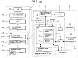
- Fig. 2 is a block diagram schematically showing a configuration of the shape measuring apparatus 100 according to the first embodiment.
- the coordinate measuring machine 1 has a controller 41, an XYZ-axis driving module 42, the probe 17, an XYZ-axis encoder 43, and an A/D converter 44.
- the XYZ-axis driving module 42 drives the probe 17 by control from the controller 41.
- the XYZ-axis encoder 43 detects a signal based on contact of the contact piece 17a (stylus tip 17a) on the top of the probe 17.
- a contact signal by contact between the contact piece 17a (stylus tip 17a) and the workpiece 31 is supplied to the computer body 21 through the A/D converter 44, and is temporarily stored in memory 52.
- the controller 41 has a CPU (Central Processing Unit) 411 and a program storage module 412.
- the program storage module 412 is, for example, an HDD (Hard Disk Drive), and has a function of storing a program used in three-dimensional measurement.
- the CPU 411 reads the program out of the program storage module 412, and controls the XYZ-axis driving module 42.
- the CPU 411 is called a first arithmetic module.
- the CPU 41 executes the programs read out, and functions as a movement speed calculation module 411a and a contact piece (stylus tip) movement control module 411b.
- the movement speed calculation module 411a has a function of calculating a movement speed of the contact piece 17a (stylus tip 17a) sequentially from the starting point side every plural sections based on path information (a PCC curve group etc. described below) received from the computer 2.
- the contact piece (stylus tip) movement control module 411b has a function of moving the contact piece 17a (stylus tip 17a) at the calculated movement speed in the section in which the movement speed is already calculated by the movement speed calculation module 411a.
- the computer body 21 has a CPU 51, the memory 52, a program storage module 53, workpiece memory 54, a display control module 55, and interfaces (I/F) 56 to 58.
- the CPU 51 receives instruction information (input information) about an operator inputted from the keyboard 22 and the mouse 23 through the interface 56. Also, the CPU 51 receives XYZ coordinates (input information) detected by the XYZ-axis encoder 43 and digitally converted by the A/D converter 44 through the memory 52. The CPU 51 executes, for example, analytical processing of a measured value of the workpiece 31 and stage movement by the XYZ-axis driving module 42 based on the input information, instructions of the operator and a program stored in the program storage module 53. In addition, the CPU 51 is called a second arithmetic module.
- the CPU 51 functions as a path information conversion module (RI conversion module) 51a, a path information division module (RI division module) 51b and a path information output module (RI output module) 51c by the programs read out.
- RI conversion module path information conversion module
- RI division module path information division module
- RI output module path information output module
- the path information) conversion module (RI conversion module) 51a has a function of converting a design value (NURBS (Non-Uniform Rational B-Spline) data) of the workpiece 31 received through the interface 58 from an external CAD system (not shown) into path information about a PCC (Parametric Cubic Curves) curve etc.
- the path information division module (RI division module) 51b has a function of dividing the PCC curve into plural segments (hereinafter also called a section).
- the path information output module (RI output module) 51c has a function of outputting path information about the PCC curve divided into the plural segments to the controller 41.
- the programs stored in the program storage module 53 include, for example, a PART program in which path information used as a movement path of the workpiece 31 is programmed, and other programs for implementing the path information conversion module (RI conversion module) 51a, the path information division module (RI division module) 51b and the path information output module (RI output module) 51c.
- the CPU 51 and the program storage module 53 described above function as a data control module 59 for outputting division path information generated by dividing path information based on design value data into plural sections to the controller 41.
- the workpiece memory 54 provides a workpiece area for various processing of the CPU 51.
- the printer 25 prints a measured result etc. of the coordinate measuring machine 1 through the interface 57.
- the display control module 55 displays, for example, an execution screen of the PART program and measured data on the monitor 24.
- Fig. 3 is a diagram showing a relation between a NURBS curve and the PCC curve.
- NURBS data having a parameter and a coordinate value of a control point
- a shape of the workpiece 31 can be represented by the NURBS curve and a NURBS curved surface.
- representation is enabled by the NURBS data, so that the whole shape of the workpiece 31 can be collectively represented by the NURBS data.
- path information about movement of the contact piece 17a (stylus tip 17a) including a curve, a circular arc and a straight line can he collectively represented by the NURBS data to generate the PCC curve based on this NURBS data.
- the PCC curve L_PCC used as the path information is a curve in which the NURBS curve L_NURBS is offset in the normal direction.
- an offset amount OFFSET is a value in which a reference deflection is subtracted from a radius of the contact piece 17a (stylus tip 17a).
- the CPU 41 performs control so that the center of a sphere of the contact piece 17a (stylus tip 17a) passes on this PCC curve.
- Fig. 4 is a diagram schematically showing a configuration of the PCC curve.
- the PCC curve L_PCC is divided into plural segments by points P.
- each of the segments is also constructed of the PCC curve.
- An ending point of each of the segments results in a starting point of the next segment (PCC curve).
- coordinates of a starting point of any PCC curve are set at (K X0 , K Y0 , K Z0 ), and a length of a straight line between a starting point and an ending point in its PCC curve is set at D.
- coordinates ⁇ X(S), Y(S), Z(S) ⁇ in any position on the PCC curve are expressed by the following Formula (1).
- Fig. 5 is a flowchart showing a control method of nominal scanning measurement of the shape measuring apparatus 100 according to the first embodiment. This method calculates a maximum speed of probe movement in the nominal scanning measurement of the shape measuring apparatus 100. The maximum speed of the nominal scanning measurement is calculated by the movement speed calculation module 411a of the CPU 411 of the controller 41.
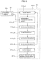
- Fig. 6 is a block diagram schematically showing a configuration of the movement speed calculation module 411a. A method for calculating a maximum speed of the ith segment (i is any integer more than or equal to 0 and less than or equal to n) from the starting point side of n segments (n is a positive integer) will hereinafter be described. First, a command from the CPU 51 is received, and a count module 411a_1 sets a value of i at "0" (step S11). Accordingly, the leading segment is specified as a measurement target segment.
- measurement parameters are given from the CPU 51 of the computer body 21 of the computer 2 to the CPU 411 of the controller 41 of the coordinate measuring machine 1 (step S12).
- the measurement parameters created by the path information conversion module (RI conversion module) 51a and the path information division module (RI division module) 51b are outputted from the path information output module (RI output module) 51c to a measurement parameter receiving module 41 a_2 of the movement speed calculation module 411a.
- D indicates a length (shortest distance) of a straight line ranging from a starting point and an ending point of a measurement target segment.
- the starting point of the measurement target segment matches with an ending point of the previous segment
- the ending point of the measurement target segment matches with a starting point of the next segment.
- K X0 to K X3 , K Y0 to K Y3 , K Z0 to K Z3 indicate coefficients of each of the coordinates of X, Y, Z, respectively.
- K X0 to K X3 , K Y0 to K Y3 , K Z0 to K Z3 and D are included in the measurement parameters given to the coordinate measuring machine 1 by the computer 2.
- the measurement parameters include an equivalent radius R1 (hereinafter also called a curvature radius R1
- the curvature radius R1 corresponds to a first curvature radius.
- the curvature radius R1 corresponds to a first curvature radius.
- the curve length Ls indicates a length of a PCC curve connecting a starting point to an ending point of a measurement target segment.
- the curve length Ls can be obtained approximately, for example, by dividing the PCC curve connecting the starting point to the ending point of the measurement target segment into plural straight lines and calculating the sum of lengths of the respective straight lines.
- the specified measurement speed Vspec represents a specified speed of shape measurement, inputted to the computer 2 through the keyboard 22 or the mouse 23 before the shape measurement.
- the shape measuring apparatus 100 moves the probe 17 at a speed which does not exceed the specified measurement speed Vspec, and makes the shape measurement.
- the equivalent radius R1 is calculated by the path information division module (R1 division module) 51b.
- a method for calculating the equivalent radius R1 will hereinafter be described concretely.
- Fig. 7 is a diagram showing the method for calculating the equivalent radius R1.
- points P1 to P4 for dividing a PCC curve L_PCC are present, and a measurement target segment is set at a segment between a starting point P2 and an ending point P3.
- the PCC curve L_PCC between the starting point P2 and the ending point P3 is first divided into four equal parts.
- the starting point P2 is connected to the ending point P3 by a straight line Ld and a length D of the straight line is divided into four equal parts.
- straight lines Lv1 to Lv3 orthogonal to the straight line Ld through division points of the straight line Ld divided into four equal parts are drawn.
- points of intersection between the straight lines Lv1 to Lv3 and the PCC curve L_PCC between the starting point P2 and the ending point P3 are set at division points of the PCC curve L_PCC between the starting point P2 and the ending point P3.
- the division points of the PCC curve L_PCC between the starting point P2 and the ending point P3 divided into four equal parts are set at division points P21, P22 and P23 sequentially from the side of the starting point P2.
- circles drawn through three continuous points of the starting point P2 are set.
- the circle drawn through the starting point P2 is set at a circle r11.
- the circle drawn through the division points P21, P22 and P23 is set at a circle r12.
- the circle drawn through the division points P22 and P23 and the ending point P3 is set at a circle r13.
- radii R11, R12 and R 13 of the circles r11, r12 and r13 are obtained.
- R11 >R 12>R 13 is obtained.
- a curvature of a curve formed by the starting point P2 is the smallest
- a curvature of a curve formed by the division points P22 and P23 and the ending point P3 is the largest.
- the smallest radius of the radii R11, R12 and R13 is set at the equivalent radius R1.
- R13 is set as the equivalent radius R1. That is, it can be understood that a maximum curvature of the PCC curve constructing a target segment is estimated and a curvature radius corresponding to the maximum curvature is set as the equivalent radius R1.
- an equivalent radius calculation module (R2 calculation module of Fig. 6 ) 411a_3 of the movement speed calculation module 411a calculates an equivalent radius R2 (hereinafter also called a curvature radius R2.
- R2 equivalent radius
- the curvature radius R2 corresponds to a second curvature radius.
- Fig. 8 is a diagram showing a relation between a measurement target segment and a segment next to the measurement target segment.
- a straight line L1 connecting a starting point P1 to an ending point P2 of the measurement target segment is drawn.
- a straight line L2 connecting a starting point (that is, the ending point of the measurement target segment) P2 to an ending point P3 of the segment next to the measurement target segment is drawn.
- an angle A between the straight line L1 and the straight line L2 is calculated.
- the angle A can be understood as a supplementary angle of an angle formed by two continuous segments (an angle joined between two continuous segments).
- a data dependence limiting speed table is previously stored in the equivalent radius calculation module (R2 calculation module of Fig. 6 ) 411a_3 of the movement speed calculation module 411a.
- a value of a data dependence limiting speed Vd1 is associated with the angle A.
- Fig. 9 is a diagram showing an example of the data dependence limiting speed table.
- the data dependence limiting speed Vd1 is not set, but in the range of 5° ⁇ A ⁇ 25°, the data dependence limiting speed Vd1 is set in increments of 5°.
- the data dependence limiting speed Vd1 is set in increments of 10°.
- the data dependence limiting speed Vd1 is not set and an error determination is made.
- C and D are predetermined values, and are previously stored in, for example, the equivalent radius calculation module 411a_3.
- the equivalent radius calculation module 411a_3 properly refers to the values of C and D, and determines the size of the data dependence limiting speed Vd1, and calculates the equivalent radius R2 using Formula (2).
- an effective radius setting module (R3 setting module of Fig. 6 ) 411a_4 of the movement speed calculation module 411a selects a smaller value from among the equivalent radii R1 and R2, and sets the smaller value as an effective radius R3 (step S 14).
- a limiting speed curve is previously stored in a limiting speed calculation module (Vd2 calculation module of Fig. 6 ) 411a_5 of the movement speed calculation module 411a.
- Fig. 10 is a graph showing the limiting speed curve stored in the limiting speed calculation module 411a_5.
- limiting speed curves V1 and V2 are given by the following Formulas (3) and (4).
- the Vd2 calculation module 411a_5 of the movement speed calculation module 411a refers to a limiting speed table, and obtains a limiting speed Vd2 corresponding to a value of the effective radius R3 (step S15).
- a maximum speed calculation module (VBi calculation module of Fig. 6 ) 411a_6 of the movement speed calculation module 411 a sets a smaller speed of the limiting speed Vd2 and a value in which the specified measurement speed Vspec is multiplied by a coefficient C (C is any positive value) as a maximum speed VBi of shape measurement of the ith segment (step S16).
- the coefficient C is called an override volume, and the specified measurement speed Vspec is multiplied for the safety of measurement. That is, by obtaining 0 ⁇ C ⁇ 1, the probe 17 can surely be prevented from being moved at a speed higher than or equal to the specified measurement speed Vspec during shape measurement.
- the maximum speed calculation module (VBi calculation module of Fig. 6 ) 411a_6 of the movement speed calculation module 411a outputs information indicating the calculated maximum speeds VB1 to VBn to an output module 411a_7.
- the output module 411a_7 outputs the information) indicating the maximum speeds VB1 to VBn to the contact piece (stylus tip) movement control module 411b.
- the coordinate measuring machine 1 makes shape measurement along a PCC curve at a speed lower than the maximum speeds VB1 to VBn in each segment. Accordingly, scanning measurement can properly be made at a speed lower than or equal to the specified measurement speed and a limiting speed determined by shape.
- the equivalent radius R1 is calculated for a measurement target segment, even when the measurement target segment has the portion with a large curvature, the maximum speed VBi can be decreased sufficiently. Consequently, the coordinate measuring machine 1 can well scan the portion with a large curvature in the measurement target segment.
- the equivalent radius R2 is calculated based on an angle between a measurement target segment and a segment next to the measurement target segment.
- shape measurement by a movement path made of the PCC curve can be made by moving the probe 17 at the calculated maximum speed VBi or lower in each segment.
- a movement speed is preferably set at the largest possible value in the range of a low speed lower than or equal to the maximum speed VBi.
- Patent Reference 2 discloses that measurement parameters such as a movement speed in each section ranging from a starting point to an ending point of a movement path are calculated backward from the ending point of the movement path in nominal scanning measurement.
- the nominal scanning measurement of a shape measuring apparatus cannot be started until calculation of the measurement parameters such as the movement speed is completed after an initial parameter of measurement is inputted.
- a problem that the time necessary to make the nominal scanning measurement of the shape measuring apparatus is long occurs.
- the maximum speed VBi can be calculated sequentially from a segment of the starting point side of the PCC curve. Hence, by sequentially outputting the calculated maximum speed VBi, shape measurement can also be started without waiting the completion of calculation of the maximum speeds VBi of all the segments. Hence, according to the present embodiment, the time necessary to make the nominal scanning measurement of the shape measuring apparatus can be reduced.
- the shape measuring apparatus 200 is a modified example of the shape measuring apparatus 100 according to the first embodiment, and has a function of deciding a speed pattern conforming to a PCC curve based on a maximum speed VBi.
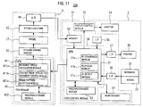
- Fig. 11 is a block diagram schematically showing a configuration of the shape measuring apparatus 200 according to the second embodiment.
- a controller 45 and a CPU 451 of a coordinate measuring machine 4 correspond to the controller 41 and the CPU 411, respectively.
- the CPU 451 has a movement speed calculation module 411a, a contact piece (stylus tip) movement control module 411b and a speed pattern selection module 451c. Since a configuration of the coordinate measuring machine 4 other than the speed pattern selection module 451c is similar to that of the coordinate measuring machine 1, description is omitted.
- Fig. 12 is a diagram showing patterns of changes in speed in one segment.
- an initial speed is displayed as VSi and a terminal speed is displayed as VFi.
- a maximum reach speed is displayed as VUi.
- a maximum speed in a segment is displayed as Vmax.
- Fig. 13 is a flowchart showing a speed pattern selection method according to the second embodiment.
- the speed pattern selection module 451c first compares a maximum speed VBi of a measurement target segment with a maximum speed VB(i+1) of a segment next to the measurement target segment (step S21). Then, in the case of VBi ⁇ VB(i+1), the speed pattern selection module 451c sets a terminal speed VFi of the measurement target segment at VBi (step S22). In the case of VBi>VB(i+1), the speed pattern selection module 451c sets the terminal speed VFi of the measurement target segment at VB(i+1) (step S23). Accordingly, the terminal speed VFi of the measurement target segment can surely be prevented from exceeding the maximum speed V8(i+1) of the segment next to the measurement target segment.
- the speed pattern selection module 451c determines a magnitude relation between the initial speed VSi and the terminal speed VFi of the measurement target segment (step S25).
- the speed pattern selection module 451c procceds to first pattern selection processing (step S26) in the case of VSi ⁇ VFi, and proceeds to second pattern selection processing (step S27) in the case of VSi>VFi.
- the first pattern selection processing (step S26) is processing for selecting a speed pattern allocated to the measurement target segment from speed patterns 1 to 4 (steps SP1 to SP4) corresponding to the case of VSi ⁇ VFi.
- the second pattern selection processing (step S27) is processing for selecting a speed pattern allocated to the measurement target segment from speed patterns 6 to 9 (steps SP6 to SP9) corresponding to the case of VSi>VFi. However, depending on a result of condition branch processing of the second pattern selection processing (step S27), processing returning to step S21 is performed. The processing returning to step S21 will be described below.
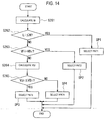
- Fig. 14 is a flowchart showing the processing in the first pattern selection processing (step S26).
- acceleration of probe movement of the coordinate measuring machine 4 is set at ⁇ .
- the speed pattern selection module 451c calculates a movement distance M in the case of accelerating with acceleration ⁇ from the initial speed VSi to the terminal speed VFi of the measurement target segment (step S261).
- the terminal speed VFi and the movement distance M are expressed by the following Formulas (5) and (6).
- Formulas (5) and (6) [Mathematical Formula 5]
- VFi ⁇ ⁇ t M + VSi
- M 1 2 ⁇ ⁇ t M 2 + VSi ⁇ t M
- the ending point of the segment is not reached only for a section accelerating with the acceleration ⁇ .
- the ending point of the segment is reached by performing acceleration, deceleration and constant speed movements after moving by the movement distance M.
- the terminal speed VFi is compared with the maximum speed VBi (step S263).
- the speed pattern selection module 451c selects a pattern 2 (PAT2) (step SP2).
- VFi#VBi that is, the case of setting the terminal speed VFi at VB(i+1)
- the case where after moving by the movement distance M, by exceeding the terminal speed VFi and accelerating with acceleration ⁇ and thereafter decelerating with acceleration - ⁇ , the terminal speed VFi is reached while moving the segment distance Li can be assumed.
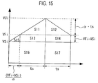
- the speed pattern selection module 451c calculates a maximum reach speed VUi (>VFi) at this time (step S264).
- Fig. 15 is a diagram showing a method for calculating the maximum reach speed from a speed pattern in step S264.
- Fig. 15 shows an example of sequentially making acceleration and deceleration with acceleration. ⁇ simply in the case of VSi ⁇ VFi.
- a movement distance shown in Fig. 15 is computed.
- an area S of the portion formed by a function showing a speed is computed.
- the area S includes areas S11 to S17 as shown in Fig. 15 .
- the areas S11 to S17 are respectively expressed by the following Formula (8).
- the area S can be expressed by the following Formula (9) from Formula (8).
- VUi VFi + ⁇ ⁇ ts
- the speed pattern selection module 451 c selects a pattern 4 (PAT4) constructed of the acceleration region, a constant speed region and the deceleration region (step SP4).
- PAT4 pattern 4
- Fig. 16 is a flowchart showing the processing in the second pattern selection processing (step S27).
- the speed pattern selection module 451c calculates a movement distance M in the case of decelerating with acceleration - ⁇ from the initial speed VSi to the terminal speed VFi of the measurement target segment (step S271).
- the terminal speed VFi and the movement distance M are expressed by the following Formulas (15) and (16).
- [Mathematical Formula 15] VFi ⁇ ⁇ ⁇ t M + VSi
- M ⁇ 1 2 ⁇ ⁇ t M 2 ⁇ VSi ⁇ t M
- the speed pattern selection module 451c compares the movement distance M with the segment length Li (step S273).
- Li>M this means that the ending point of the segment is not reached only for a section decelerating with the acceleration - ⁇ .
- the ending point of the segment is reached by performing acceleration, deceleration and constant speed movements in addition to movement by the movement distance M.
- an acceleration region and a constant speed region are formed before the deceleration region (patterns 7 to 9).
- the speed pattern selection module 451c compares the initial speed VSi with the maximum speed VBi (step S274).
- the speed pattern selection module 451c selects a pattern 7 (PAT7) (step SP7).
- PAT7 pattern 7
- VSi#VBi that is, the case of setting the terminal speed VFi at VB(i+1)
- the initial speed VSi is exceeded and acceleration is made with acceleration ⁇ and thereafter deceleration is made with acceleration - ⁇ .
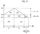
- the speed pattern selection module 451c calculates a maximum reach speed VUi (>VFi) at this time (step S275).
- Fig. 17 is a diagram showing a method for calculating the maximum reach speed from a speed pattern in step S275.
- Fig. 15 shows an example of sequentially making acceleration and deceleration with acceleration ⁇ simply in the case of VSi>VFi.
- a movement distance shown in Fig. 17 is computed.
- an area S of the portion formed by a function showing a speed is computed.
- the area S includes areas S21 to S27 as shown in Fig. 17 .
- the areas S21 to S27 are respectively expressed by the following Formula (18).
- S 26 ts ⁇ VFi
- S 27 VSi ⁇ VFi ⁇ + ts ⁇ VFi
- the area S can be expressed by the following Formula (19) from Formula (18).
- Formula (20) is obtained.
- [Mathematical Formula 20] ⁇ ⁇ ts 2 + 2 ts ⁇ VSi + VSi ⁇ VFi 2 2 ⁇ + VSi ⁇ VFi 2 2 ⁇ + VFi VSi ⁇ VFi ⁇ ⁇ S 0
- VUi VSi + ⁇ ⁇ ts
- the speed pattern selection module 451c selects a pattern 9 (PAT9) constructed of the acceleration region, a constant speed region and the deceleration region (step SP9).
- movement time t1 of the acceleration region is t1-(VBi-VSi)/ ⁇ .
- the speed pattern selection module 451 first obtains a settable initial speed VSbi (step S277).
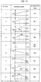
- Fig. 18 is a diagram showing an example of a movement path and a speed pattern. As shown in Fig. 18 , the speed patterns corresponding to a PCC curve L_PCC can be allocated to segments SEG1 to SEG 13.
- the shape measuring apparatus 300 is a modified example of the shape measuring apparatus 100 according to the first embodiment, and can more speed up shape measuring operation.
- a configuration of the shape measuring apparatus 300 is similar to that of the shape measuring apparatus 100, description is omitted.
- the PCC curve indicating the movement path is divided into plural segments.
- the segments with the same or approximate effective radius R may be continuously arranged.
- the segments with the same or approximate effective radius R also have the same or approximate maximum speed VBi. Consequently, the segments with the same or approximate effective radius R3 could be treated as one block.
- Fig. 19 is a diagram schematically showing segment arrangement in the case of blocking segments SEG1 to SEG13 constructing a PCC curve indicating a movement path.
- a limiting speed calculation module (Vd2 calculation module of Fig. 6 ) 411a_of a movement speed calculation module 411a gathers segments with the same or approximate effective radius R3 into blocks BLOCK1 to BLOCK4. Accordingly, the movement speed calculation module 411a calculates maximum speeds VBi for the blocks BLOCK1 to BLOCK4.
- a coordinate measuring machine 1 could control a movement speed of a probe 17 based on the maximum speed VBi set every block.
- Fig. 19 shows the example of blocking all the segments, but a segment whose effective radius R is not the same or approximate may be present between blocks.
- Fig. 20 is a diagram schematically showing segment arrangement in the case where a segment whose effective radius R is not the same or approximate is present between blocks.
- the coordinate measuring machine 1 could control the movement speed based on the maximum speed set every block and every segment which is not blocked.
- the segment which is not blocked (that is, a single segment) can be treated as one block. Consequently, in Fig. 20 , the blocks and the segments which are not blocked are displayed as blocks BLOCK1 to BLOCK6.
- variations in the effective radius R could be provided with an allowable range.
- the variations could be defined as the range within x% of the average value of the effective radii R of the blocked segments.
- the speed pattern deciding method described in the second embodiment is applied to the shape measuring apparatus 300 according to the third embodiment.
- the speed pattern is set for each segment.
- the speed pattern deciding method described in the second embodiment can be applied by treating blocks created by the shape measuring apparatus 400 according to the fourth embodiment as one block. In this case, the speed pattern can be allocated to each of the blocks and the segments which are not blocked.
- the number of executions of an algorithm necessary to decide the speed pattern can be reduced greatly. As a result, a speedup in shape measurement can be achieved. Further, the number of accelerations and decelerations can be reduced by blocking, so that vibration etc. generated in a coordinate measuring machine 1 can further be presented to increase accuracy of shape measurement.
- the PCC curve is used as the movement path of the probe, but this is only illustrative. Hence, cubic curves or quartic or more curves other than the PCC can naturally be used as the movement path of the probe.
- the control method of the shape measuring apparatus according to the embodiments described above can be applied by dividing the cubic curves or the quartic or more curves other than the PCC into plural segments.
- a control method of a shape measuring apparatus comprising:
- Appendix 2 The control method of a shape measuring apparatus as described in appendix 1, comprising:
- Appendix 3 The control method of a shape measuring apparatus as described in appendix 1 or 2, wherein the maximum speed is expressed by a square root function of the effective radius when the effective radius is smaller than a first value, and is expressed by a linear function of the effective radius when the effective radius is larger than the first value.
- Appendix 4 The control method of a shape measuring apparatus as described in any one of appendixes 1 to 3, wherein a speed pattern for moving the probe is decided based on the maximum speed
- Appendix 5 The control method of a shape measuring apparatus as described in appendix 4, comprising:
- Appendix 6 The control method of a shape measuring apparatus as described in appendix 5, comprising:
- Appendix 7 The control method of a shape measuring apparatus as described in appendix 5, comprising:
- Appendix 8 The control method of a shape measuring apparatus as described in appendix 7, comprising:
- Appendix 12 The control method of a shape measuring apparatus as described in appendix 10, comprising:
- Appendix 14 The control method of a shape measuring apparatus as described in appendix 13, comprising:
- Appendix 15 The control method of a shape measuring apparatus as described in appendix 13, comprising:
- Appendix 16 The control method of a shape measuring apparatus as described in appendix 13, comprising:
- Appendix 17 The control method of a shape measuring apparatus as described in appendix 16, comprising:
- Appendix 18 The control method of a shape measuring apparatus as described on appendix 16, comprising:
- Appendix 20 The control method of a shape measuring apparatus as described in any one of appendixes 4 to 18, comprising:
- Appendix 21 The control method of a shape measuring apparatus as described in appendix 19 or 20, wherein the representative value is an average value of the effective radii of the measurement target section included in the block.
- Appendix 22 The control method of a shape measuring apparatus as described in any one of appendixes 1 to 21, wherein the curve indicating the movement path of the probe is parametric cubic curves.
- a shape measuring apparatus comprises:
- Appendix 24 The shape measuring apparatus as described in appendix 23, wherein the path information division module divides the measurement target section into a plurality of division curves, and calculates a minimum radius of a circle which has the minimum radius and passes through three continuous points of a starting point of the measurement target section, an ending point of the measurement target section and a division point at which the measurement target section is divided into the plurality of division curves as the first curvature radius.
- Appendix 25 The shape measuring apparatus as described in appendix 23 or 24, wherein the maximum speed is expressed by a square root function of the effective radius when the effective radius is smaller than a first value, and is expressed by a linear function of the effective radius when the effective radius is larger than the first value.
- Appendix 26 The shape measuring apparatus as described in any one of appendixes 23 to 25, comprising:
- Appendix 27 The shape measuring apparatus as described in appendix 26, wherein the speed pattern selection module compares a first maximum speed which is the maximum speed of the measurement target section with a second maximum speed which is the maximum speed of the section next to the measurement target section, and sets the first maximum speed as a terminal speed of the measurement target section when the first maximum speed is lower than or equal to the second maximum speed, and sets the second maximum speed as the terminal speed of the measurement target section when the first maximum speed is higher than the second maximum speed.
- Appendix 28 The shape measuring apparatus as described in appendix 27, wherein when an initial speed of the measurement target section is equal to the terminal speed, the speed pattern selection module selects a speed pattern in which a constant speed is maintained at the initial speed and the probe is moved from the starting point to the ending point of the measurement target section.
- Appendix 42 The shape measuring apparatus as described in appendix 41, wherein the representative value is an average value of the effective radii of the measurement target section included in the block.
- Appendix 44 The shape measuring apparatus as described in appendix 43, wherein the representative value is an average value of the effective radii of the measurement target section included in the block.
- Appendix 46 The shape measuring apparatus as described in any one of appendixes 26 to 40, 43, 44, comprising:
Landscapes
- Physics & Mathematics (AREA)
- General Physics & Mathematics (AREA)
- Engineering & Computer Science (AREA)
- Automation & Control Theory (AREA)
- A Measuring Device Byusing Mechanical Method (AREA)
- Length Measuring Devices With Unspecified Measuring Means (AREA)
Applications Claiming Priority (1)
| Application Number | Priority Date | Filing Date | Title |
|---|---|---|---|
| JP2012161772A JP6063161B2 (ja) | 2012-07-20 | 2012-07-20 | 形状測定装置及び形状測定装置の制御方法 |
Publications (3)
| Publication Number | Publication Date |
|---|---|
| EP2687816A2 EP2687816A2 (en) | 2014-01-22 |
| EP2687816A3 EP2687816A3 (en) | 2015-07-15 |
| EP2687816B1 true EP2687816B1 (en) | 2016-08-24 |
Family
ID=48783136
Family Applications (1)
| Application Number | Title | Priority Date | Filing Date |
|---|---|---|---|
| EP13176698.2A Active EP2687816B1 (en) | 2012-07-20 | 2013-07-16 | Shape measuring apparatus and control method of shape measuring apparatus |
Country Status (3)
| Country | Link |
|---|---|
| US (1) | US9448052B2 (enExample) |
| EP (1) | EP2687816B1 (enExample) |
| JP (1) | JP6063161B2 (enExample) |
Families Citing this family (26)
| Publication number | Priority date | Publication date | Assignee | Title |
|---|---|---|---|---|
| US8701298B2 (en) * | 2011-06-01 | 2014-04-22 | Tesa Sa | Coordinate measuring machine |
| JP6153816B2 (ja) | 2013-08-23 | 2017-06-28 | 株式会社ミツトヨ | 形状測定装置及びロータリテーブル座標系の登録方法 |
| JP6144157B2 (ja) | 2013-08-26 | 2017-06-07 | 株式会社ミツトヨ | 形状測定装置及びv溝求心測定方法 |
| JP6219141B2 (ja) | 2013-11-27 | 2017-10-25 | 株式会社ミツトヨ | 形状測定装置及び形状測定方法 |
| JP6474216B2 (ja) * | 2014-08-29 | 2019-02-27 | 株式会社ミツトヨ | 形状測定装置、及び形状測定方法 |
| JP6107782B2 (ja) * | 2014-09-30 | 2017-04-05 | ブラザー工業株式会社 | プログラム及びレーザ加工装置 |
| EP4257248A3 (en) | 2015-02-24 | 2023-12-27 | OP-Hygiene IP GmbH | Liquid dispenser with removable mobile dispenser |
| JP2016205899A (ja) * | 2015-04-17 | 2016-12-08 | 株式会社ミツトヨ | 回転テーブルの制御方法及び装置 |
| JP6484108B2 (ja) | 2015-05-22 | 2019-03-13 | 株式会社ミツトヨ | 形状測定装置の制御方法 |
| JP6514041B2 (ja) | 2015-06-02 | 2019-05-15 | 株式会社ミツトヨ | 形状測定装置の制御方法 |
| JP6570393B2 (ja) * | 2015-09-25 | 2019-09-04 | 株式会社ミツトヨ | 形状測定装置の制御方法 |
| JP6599195B2 (ja) * | 2015-10-01 | 2019-10-30 | 株式会社ミツトヨ | 座標測定装置 |
| JP6774240B2 (ja) | 2016-07-14 | 2020-10-21 | 株式会社ミツトヨ | 形状測定装置の制御方法 |
| FR3055698B1 (fr) * | 2016-09-08 | 2018-08-17 | Safran Aircraft Engines | Procede de controle de la conformite du profil d'une surface courbe d'un element d'une turbomachine |
| JP6909574B2 (ja) | 2016-11-29 | 2021-07-28 | 株式会社ミツトヨ | 形状測定装置の制御方法 |
| JP6923361B2 (ja) * | 2017-05-29 | 2021-08-18 | 株式会社ミツトヨ | 位置計測装置の操作方法 |
| JP2019049462A (ja) * | 2017-09-08 | 2019-03-28 | 株式会社ミツトヨ | 形状測定装置の制御方法 |
| JP6932585B2 (ja) * | 2017-09-08 | 2021-09-08 | 株式会社ミツトヨ | 形状測定装置の制御方法 |
| JP7002892B2 (ja) | 2017-09-08 | 2022-01-20 | 株式会社ミツトヨ | 形状測定装置の制御方法 |
| EP3537102B1 (de) * | 2018-03-05 | 2020-05-13 | Carl Zeiss Industrielle Messtechnik GmbH | Verfahren und anordnung zum erhöhen des durchsatzes bei einer ausreichenden messgenauigkeit bei der werkstückvermessung |
| JP7186625B2 (ja) * | 2019-01-17 | 2022-12-09 | 株式会社ミツトヨ | 形状測定装置の制御方法 |
| US11204237B2 (en) | 2019-10-14 | 2021-12-21 | Mitutoyo Corporation | Method for controlling shape measuring apparatus |
| JP7448437B2 (ja) | 2020-08-06 | 2024-03-12 | 株式会社ミツトヨ | 形状測定装置の制御方法 |
| CN112284303B (zh) * | 2020-10-21 | 2021-09-14 | 常州市新创智能科技有限公司 | 一种拉挤板直线度检测装置 |
| JP7701195B2 (ja) | 2021-06-04 | 2025-07-01 | 株式会社ミツトヨ | プローブユニットの補正方法 |
| CN119002244B (zh) * | 2024-10-24 | 2025-02-14 | 零度新能源科技(广东)有限公司 | 基于机器学习的智能转舵 |
Family Cites Families (15)
| Publication number | Priority date | Publication date | Assignee | Title |
|---|---|---|---|---|
| US3866179A (en) * | 1972-09-22 | 1975-02-11 | Giddings & Lewis | Numerical control with envelope offset and automatic path segment transitions |
| JPH04109317A (ja) * | 1990-08-29 | 1992-04-10 | Matsushita Electric Works Ltd | ロボットの移動速度指令値作成法 |
| DE19529547A1 (de) | 1995-08-11 | 1997-02-13 | Zeiss Carl Fa | Verfahren zur Steuerung von Koordinatenmeßgeräten |
| JPH10254526A (ja) * | 1997-03-13 | 1998-09-25 | Toshiba Mach Co Ltd | 数値制御装置 |
| JP3610295B2 (ja) * | 2000-10-04 | 2005-01-12 | 学校法人トヨタ学園 | 自由曲面を表す曲面式を求める方法 |
| JP4068321B2 (ja) * | 2001-09-27 | 2008-03-26 | 株式会社ジェイテクト | 加工装置の加工速度設定方法及び加工装置 |
| JP3961293B2 (ja) | 2002-01-07 | 2007-08-22 | 株式会社ミツトヨ | 表面性状倣い測定方法、プログラムおよび記録媒体 |
| JP4782990B2 (ja) | 2004-05-31 | 2011-09-28 | 株式会社ミツトヨ | 表面倣い測定装置、表面倣い測定方法、表面倣い測定プログラムおよび記録媒体 |
| US7354268B2 (en) * | 2004-10-06 | 2008-04-08 | 3M Innovative Properties Company | Movement of orthodontic objects along a virtual archwire within a three-dimensional (3D) environment |
| GB0508273D0 (en) * | 2005-04-25 | 2005-06-01 | Renishaw Plc | Method for scanning the surface of a workpiece |
| JP4582080B2 (ja) * | 2006-11-06 | 2010-11-17 | 株式会社豊田中央研究所 | 送り速度最適化装置、送り速度最適化方法、プログラム |
| GB0625260D0 (en) | 2006-12-19 | 2007-01-24 | Renishaw Plc | A method for measuring a workpiece using a machine tool |
| JP5274782B2 (ja) | 2007-03-27 | 2013-08-28 | 株式会社ミツトヨ | 表面性状測定装置、表面性状測定方法及び表面性状測定プログラム |
| JP4900968B2 (ja) * | 2008-04-25 | 2012-03-21 | 株式会社ソディック | 加工制御装置 |
| JP4980458B2 (ja) * | 2010-10-27 | 2012-07-18 | ファナック株式会社 | 数値制御工作機械の加工時間予測装置 |
-
2012
- 2012-07-20 JP JP2012161772A patent/JP6063161B2/ja active Active
-
2013
- 2013-07-15 US US13/941,880 patent/US9448052B2/en active Active
- 2013-07-16 EP EP13176698.2A patent/EP2687816B1/en active Active
Also Published As
| Publication number | Publication date |
|---|---|
| US20140025336A1 (en) | 2014-01-23 |
| US9448052B2 (en) | 2016-09-20 |
| JP6063161B2 (ja) | 2017-01-18 |
| EP2687816A3 (en) | 2015-07-15 |
| JP2014021004A (ja) | 2014-02-03 |
| EP2687816A2 (en) | 2014-01-22 |
Similar Documents
| Publication | Publication Date | Title |
|---|---|---|
| EP2687816B1 (en) | Shape measuring apparatus and control method of shape measuring apparatus | |
| JP5274782B2 (ja) | 表面性状測定装置、表面性状測定方法及び表面性状測定プログラム | |
| US9915516B2 (en) | Method for controlling shape measuring apparatus | |
| US9091522B2 (en) | Shape measuring machine and method of correcting shape measurement error | |
| CN109719703B (zh) | 警告或修正示教点或示教线的位置偏移的机器人示教装置 | |
| EP2657646B1 (en) | Profile measuring method and profile measuring instrument | |
| US9097504B2 (en) | Shape measuring machine and method of correcting shape measurement error | |
| JP6050636B2 (ja) | 産業機械、産業機械の制御方法、形状測定装置及び形状測定装置の制御方法 | |
| US9541914B2 (en) | Wire electric discharge machine and calculation method for wire support positions of wire electric discharge machine | |
| CN105588533A (zh) | 形状测定装置以及形状测定方法 | |
| EP2708847B1 (en) | Method, system and program for generating a three-dimensional model | |
| US20130185010A1 (en) | Measurement coordinate correction method and coordinate measuring apparatus | |
| US20090289953A1 (en) | System and method for adjusting view of a measuring report of an object | |
| EP2546799A9 (en) | Method of aligning and three-dimensional profile evaluating system | |
| US10274297B2 (en) | Method for controlling shape measuring apparatus | |
| US20180149458A1 (en) | Control method of shape measuring apparatus | |
| KR101489072B1 (ko) | 5축 동시 구동을 통한 볼바 측정용 원추형 경로 생성 방법 | |
| JP6474216B2 (ja) | 形状測定装置、及び形状測定方法 | |
| KR101193441B1 (ko) | 3축 이송테이블을 갖는 기계의 오차 측정 방법 | |
| Gąska et al. | FAR applied | |
| KR100418179B1 (ko) | 오프라인 프로그램을 이용한 5축 3차원 측정기의 차체패널의 심 부위 측정 방법 | |
| JP2006105717A (ja) | 高さデータ推定方法、高さデータ推定用プログラム及び3次元形状測定装置 | |
| JP2009014504A (ja) | 計測装置および計測方法 |
Legal Events
| Date | Code | Title | Description |
|---|---|---|---|
| PUAI | Public reference made under article 153(3) epc to a published international application that has entered the european phase |
Free format text: ORIGINAL CODE: 0009012 |
|
| AK | Designated contracting states |
Kind code of ref document: A2 Designated state(s): AL AT BE BG CH CY CZ DE DK EE ES FI FR GB GR HR HU IE IS IT LI LT LU LV MC MK MT NL NO PL PT RO RS SE SI SK SM TR |
|
| AX | Request for extension of the european patent |
Extension state: BA ME |
|
| PUAL | Search report despatched |
Free format text: ORIGINAL CODE: 0009013 |
|
| RIC1 | Information provided on ipc code assigned before grant |
Ipc: G01B 21/04 20060101AFI20150603BHEP Ipc: G01B 5/008 20060101ALI20150603BHEP |
|
| AK | Designated contracting states |
Kind code of ref document: A3 Designated state(s): AL AT BE BG CH CY CZ DE DK EE ES FI FR GB GR HR HU IE IS IT LI LT LU LV MC MK MT NL NO PL PT RO RS SE SI SK SM TR |
|
| AX | Request for extension of the european patent |
Extension state: BA ME |
|
| RIC1 | Information provided on ipc code assigned before grant |
Ipc: G01B 21/04 20060101AFI20150610BHEP Ipc: G01B 5/008 20060101ALI20150610BHEP |
|
| 17P | Request for examination filed |
Effective date: 20151215 |
|
| RBV | Designated contracting states (corrected) |
Designated state(s): AL AT BE BG CH CY CZ DE DK EE ES FI FR GB GR HR HU IE IS IT LI LT LU LV MC MK MT NL NO PL PT RO RS SE SI SK SM TR |
|
| GRAP | Despatch of communication of intention to grant a patent |
Free format text: ORIGINAL CODE: EPIDOSNIGR1 |
|
| INTG | Intention to grant announced |
Effective date: 20160223 |
|
| RAP1 | Party data changed (applicant data changed or rights of an application transferred) |
Owner name: MITUTOYO CORPORATION |
|
| GRAS | Grant fee paid |
Free format text: ORIGINAL CODE: EPIDOSNIGR3 |
|
| GRAA | (expected) grant |
Free format text: ORIGINAL CODE: 0009210 |
|
| AK | Designated contracting states |
Kind code of ref document: B1 Designated state(s): AL AT BE BG CH CY CZ DE DK EE ES FI FR GB GR HR HU IE IS IT LI LT LU LV MC MK MT NL NO PL PT RO RS SE SI SK SM TR |
|
| REG | Reference to a national code |
Ref country code: GB Ref legal event code: FG4D |
|
| REG | Reference to a national code |
Ref country code: CH Ref legal event code: EP |
|
| REG | Reference to a national code |
Ref country code: AT Ref legal event code: REF Ref document number: 823510 Country of ref document: AT Kind code of ref document: T Effective date: 20160915 |
|
| REG | Reference to a national code |
Ref country code: IE Ref legal event code: FG4D |
|
| REG | Reference to a national code |
Ref country code: DE Ref legal event code: R096 Ref document number: 602013010541 Country of ref document: DE |
|
| REG | Reference to a national code |
Ref country code: LT Ref legal event code: MG4D |
|
| REG | Reference to a national code |
Ref country code: NL Ref legal event code: MP Effective date: 20160824 |
|
| REG | Reference to a national code |
Ref country code: AT Ref legal event code: MK05 Ref document number: 823510 Country of ref document: AT Kind code of ref document: T Effective date: 20160824 |
|
| PG25 | Lapsed in a contracting state [announced via postgrant information from national office to epo] |
Ref country code: HR Free format text: LAPSE BECAUSE OF FAILURE TO SUBMIT A TRANSLATION OF THE DESCRIPTION OR TO PAY THE FEE WITHIN THE PRESCRIBED TIME-LIMIT Effective date: 20160824 Ref country code: FI Free format text: LAPSE BECAUSE OF FAILURE TO SUBMIT A TRANSLATION OF THE DESCRIPTION OR TO PAY THE FEE WITHIN THE PRESCRIBED TIME-LIMIT Effective date: 20160824 Ref country code: LT Free format text: LAPSE BECAUSE OF FAILURE TO SUBMIT A TRANSLATION OF THE DESCRIPTION OR TO PAY THE FEE WITHIN THE PRESCRIBED TIME-LIMIT Effective date: 20160824 Ref country code: IT Free format text: LAPSE BECAUSE OF FAILURE TO SUBMIT A TRANSLATION OF THE DESCRIPTION OR TO PAY THE FEE WITHIN THE PRESCRIBED TIME-LIMIT Effective date: 20160824 Ref country code: NL Free format text: LAPSE BECAUSE OF FAILURE TO SUBMIT A TRANSLATION OF THE DESCRIPTION OR TO PAY THE FEE WITHIN THE PRESCRIBED TIME-LIMIT Effective date: 20160824 Ref country code: RS Free format text: LAPSE BECAUSE OF FAILURE TO SUBMIT A TRANSLATION OF THE DESCRIPTION OR TO PAY THE FEE WITHIN THE PRESCRIBED TIME-LIMIT Effective date: 20160824 Ref country code: NO Free format text: LAPSE BECAUSE OF FAILURE TO SUBMIT A TRANSLATION OF THE DESCRIPTION OR TO PAY THE FEE WITHIN THE PRESCRIBED TIME-LIMIT Effective date: 20161124 |
|
| PG25 | Lapsed in a contracting state [announced via postgrant information from national office to epo] |
Ref country code: SE Free format text: LAPSE BECAUSE OF FAILURE TO SUBMIT A TRANSLATION OF THE DESCRIPTION OR TO PAY THE FEE WITHIN THE PRESCRIBED TIME-LIMIT Effective date: 20160824 Ref country code: GR Free format text: LAPSE BECAUSE OF FAILURE TO SUBMIT A TRANSLATION OF THE DESCRIPTION OR TO PAY THE FEE WITHIN THE PRESCRIBED TIME-LIMIT Effective date: 20161125 Ref country code: PT Free format text: LAPSE BECAUSE OF FAILURE TO SUBMIT A TRANSLATION OF THE DESCRIPTION OR TO PAY THE FEE WITHIN THE PRESCRIBED TIME-LIMIT Effective date: 20161226 Ref country code: ES Free format text: LAPSE BECAUSE OF FAILURE TO SUBMIT A TRANSLATION OF THE DESCRIPTION OR TO PAY THE FEE WITHIN THE PRESCRIBED TIME-LIMIT Effective date: 20160824 Ref country code: LV Free format text: LAPSE BECAUSE OF FAILURE TO SUBMIT A TRANSLATION OF THE DESCRIPTION OR TO PAY THE FEE WITHIN THE PRESCRIBED TIME-LIMIT Effective date: 20160824 Ref country code: AT Free format text: LAPSE BECAUSE OF FAILURE TO SUBMIT A TRANSLATION OF THE DESCRIPTION OR TO PAY THE FEE WITHIN THE PRESCRIBED TIME-LIMIT Effective date: 20160824 |
|
| PG25 | Lapsed in a contracting state [announced via postgrant information from national office to epo] |
Ref country code: RO Free format text: LAPSE BECAUSE OF FAILURE TO SUBMIT A TRANSLATION OF THE DESCRIPTION OR TO PAY THE FEE WITHIN THE PRESCRIBED TIME-LIMIT Effective date: 20160824 Ref country code: EE Free format text: LAPSE BECAUSE OF FAILURE TO SUBMIT A TRANSLATION OF THE DESCRIPTION OR TO PAY THE FEE WITHIN THE PRESCRIBED TIME-LIMIT Effective date: 20160824 |
|
| REG | Reference to a national code |
Ref country code: DE Ref legal event code: R097 Ref document number: 602013010541 Country of ref document: DE |
|
| PG25 | Lapsed in a contracting state [announced via postgrant information from national office to epo] |
Ref country code: SK Free format text: LAPSE BECAUSE OF FAILURE TO SUBMIT A TRANSLATION OF THE DESCRIPTION OR TO PAY THE FEE WITHIN THE PRESCRIBED TIME-LIMIT Effective date: 20160824 Ref country code: PL Free format text: LAPSE BECAUSE OF FAILURE TO SUBMIT A TRANSLATION OF THE DESCRIPTION OR TO PAY THE FEE WITHIN THE PRESCRIBED TIME-LIMIT Effective date: 20160824 Ref country code: BG Free format text: LAPSE BECAUSE OF FAILURE TO SUBMIT A TRANSLATION OF THE DESCRIPTION OR TO PAY THE FEE WITHIN THE PRESCRIBED TIME-LIMIT Effective date: 20161124 Ref country code: BE Free format text: LAPSE BECAUSE OF FAILURE TO SUBMIT A TRANSLATION OF THE DESCRIPTION OR TO PAY THE FEE WITHIN THE PRESCRIBED TIME-LIMIT Effective date: 20160824 Ref country code: CZ Free format text: LAPSE BECAUSE OF FAILURE TO SUBMIT A TRANSLATION OF THE DESCRIPTION OR TO PAY THE FEE WITHIN THE PRESCRIBED TIME-LIMIT Effective date: 20160824 Ref country code: SM Free format text: LAPSE BECAUSE OF FAILURE TO SUBMIT A TRANSLATION OF THE DESCRIPTION OR TO PAY THE FEE WITHIN THE PRESCRIBED TIME-LIMIT Effective date: 20160824 Ref country code: DK Free format text: LAPSE BECAUSE OF FAILURE TO SUBMIT A TRANSLATION OF THE DESCRIPTION OR TO PAY THE FEE WITHIN THE PRESCRIBED TIME-LIMIT Effective date: 20160824 |
|
| PLBE | No opposition filed within time limit |
Free format text: ORIGINAL CODE: 0009261 |
|
| STAA | Information on the status of an ep patent application or granted ep patent |
Free format text: STATUS: NO OPPOSITION FILED WITHIN TIME LIMIT |
|
| 26N | No opposition filed |
Effective date: 20170526 |
|
| PG25 | Lapsed in a contracting state [announced via postgrant information from national office to epo] |
Ref country code: SI Free format text: LAPSE BECAUSE OF FAILURE TO SUBMIT A TRANSLATION OF THE DESCRIPTION OR TO PAY THE FEE WITHIN THE PRESCRIBED TIME-LIMIT Effective date: 20160824 |
|
| REG | Reference to a national code |
Ref country code: CH Ref legal event code: PL |
|
| REG | Reference to a national code |
Ref country code: IE Ref legal event code: MM4A |
|
| REG | Reference to a national code |
Ref country code: FR Ref legal event code: ST Effective date: 20180330 |
|
| PG25 | Lapsed in a contracting state [announced via postgrant information from national office to epo] |
Ref country code: IE Free format text: LAPSE BECAUSE OF NON-PAYMENT OF DUE FEES Effective date: 20170716 Ref country code: CH Free format text: LAPSE BECAUSE OF NON-PAYMENT OF DUE FEES Effective date: 20170731 Ref country code: LI Free format text: LAPSE BECAUSE OF NON-PAYMENT OF DUE FEES Effective date: 20170731 |
|
| PG25 | Lapsed in a contracting state [announced via postgrant information from national office to epo] |
Ref country code: FR Free format text: LAPSE BECAUSE OF NON-PAYMENT OF DUE FEES Effective date: 20170731 |
|
| PG25 | Lapsed in a contracting state [announced via postgrant information from national office to epo] |
Ref country code: LU Free format text: LAPSE BECAUSE OF NON-PAYMENT OF DUE FEES Effective date: 20170716 |
|
| PG25 | Lapsed in a contracting state [announced via postgrant information from national office to epo] |
Ref country code: MT Free format text: LAPSE BECAUSE OF NON-PAYMENT OF DUE FEES Effective date: 20170716 |
|
| PG25 | Lapsed in a contracting state [announced via postgrant information from national office to epo] |
Ref country code: AL Free format text: LAPSE BECAUSE OF FAILURE TO SUBMIT A TRANSLATION OF THE DESCRIPTION OR TO PAY THE FEE WITHIN THE PRESCRIBED TIME-LIMIT Effective date: 20160824 |
|
| PG25 | Lapsed in a contracting state [announced via postgrant information from national office to epo] |
Ref country code: MC Free format text: LAPSE BECAUSE OF FAILURE TO SUBMIT A TRANSLATION OF THE DESCRIPTION OR TO PAY THE FEE WITHIN THE PRESCRIBED TIME-LIMIT Effective date: 20160824 Ref country code: HU Free format text: LAPSE BECAUSE OF FAILURE TO SUBMIT A TRANSLATION OF THE DESCRIPTION OR TO PAY THE FEE WITHIN THE PRESCRIBED TIME-LIMIT; INVALID AB INITIO Effective date: 20130716 |
|
| PG25 | Lapsed in a contracting state [announced via postgrant information from national office to epo] |
Ref country code: CY Free format text: LAPSE BECAUSE OF NON-PAYMENT OF DUE FEES Effective date: 20160824 |
|
| PG25 | Lapsed in a contracting state [announced via postgrant information from national office to epo] |
Ref country code: MK Free format text: LAPSE BECAUSE OF FAILURE TO SUBMIT A TRANSLATION OF THE DESCRIPTION OR TO PAY THE FEE WITHIN THE PRESCRIBED TIME-LIMIT Effective date: 20160824 |
|
| PG25 | Lapsed in a contracting state [announced via postgrant information from national office to epo] |
Ref country code: TR Free format text: LAPSE BECAUSE OF FAILURE TO SUBMIT A TRANSLATION OF THE DESCRIPTION OR TO PAY THE FEE WITHIN THE PRESCRIBED TIME-LIMIT Effective date: 20160824 |
|
| PG25 | Lapsed in a contracting state [announced via postgrant information from national office to epo] |
Ref country code: IS Free format text: LAPSE BECAUSE OF FAILURE TO SUBMIT A TRANSLATION OF THE DESCRIPTION OR TO PAY THE FEE WITHIN THE PRESCRIBED TIME-LIMIT Effective date: 20161224 |
|
| PGFP | Annual fee paid to national office [announced via postgrant information from national office to epo] |
Ref country code: DE Payment date: 20250722 Year of fee payment: 13 |
|
| PGFP | Annual fee paid to national office [announced via postgrant information from national office to epo] |
Ref country code: GB Payment date: 20250722 Year of fee payment: 13 |