EP2687477A1 - Nutzfahrzeug - Google Patents
Nutzfahrzeug Download PDFInfo
- Publication number
- EP2687477A1 EP2687477A1 EP13189434.7A EP13189434A EP2687477A1 EP 2687477 A1 EP2687477 A1 EP 2687477A1 EP 13189434 A EP13189434 A EP 13189434A EP 2687477 A1 EP2687477 A1 EP 2687477A1
- Authority
- EP
- European Patent Office
- Prior art keywords
- work
- traveling
- generator
- engine
- motor
- Prior art date
- Legal status (The legal status is an assumption and is not a legal conclusion. Google has not performed a legal analysis and makes no representation as to the accuracy of the status listed.)
- Granted
Links
Images


Classifications
-
- B—PERFORMING OPERATIONS; TRANSPORTING
- B60—VEHICLES IN GENERAL
- B60K—ARRANGEMENT OR MOUNTING OF PROPULSION UNITS OR OF TRANSMISSIONS IN VEHICLES; ARRANGEMENT OR MOUNTING OF PLURAL DIVERSE PRIME-MOVERS IN VEHICLES; AUXILIARY DRIVES FOR VEHICLES; INSTRUMENTATION OR DASHBOARDS FOR VEHICLES; ARRANGEMENTS IN CONNECTION WITH COOLING, AIR INTAKE, GAS EXHAUST OR FUEL SUPPLY OF PROPULSION UNITS IN VEHICLES
- B60K6/00—Arrangement or mounting of plural diverse prime-movers for mutual or common propulsion, e.g. hybrid propulsion systems comprising electric motors and internal combustion engines ; Control systems therefor, i.e. systems controlling two or more prime movers, or controlling one of these prime movers and any of the transmission, drive or drive units Informative references: mechanical gearings with secondary electric drive F16H3/72; arrangements for handling mechanical energy structurally associated with the dynamo-electric machine H02K7/00; machines comprising structurally interrelated motor and generator parts H02K51/00; dynamo-electric machines not otherwise provided for in H02K see H02K99/00
- B60K6/20—Arrangement or mounting of plural diverse prime-movers for mutual or common propulsion, e.g. hybrid propulsion systems comprising electric motors and internal combustion engines ; Control systems therefor, i.e. systems controlling two or more prime movers, or controlling one of these prime movers and any of the transmission, drive or drive units Informative references: mechanical gearings with secondary electric drive F16H3/72; arrangements for handling mechanical energy structurally associated with the dynamo-electric machine H02K7/00; machines comprising structurally interrelated motor and generator parts H02K51/00; dynamo-electric machines not otherwise provided for in H02K see H02K99/00 the prime-movers consisting of electric motors and internal combustion engines, e.g. HEVs
- B60K6/22—Arrangement or mounting of plural diverse prime-movers for mutual or common propulsion, e.g. hybrid propulsion systems comprising electric motors and internal combustion engines ; Control systems therefor, i.e. systems controlling two or more prime movers, or controlling one of these prime movers and any of the transmission, drive or drive units Informative references: mechanical gearings with secondary electric drive F16H3/72; arrangements for handling mechanical energy structurally associated with the dynamo-electric machine H02K7/00; machines comprising structurally interrelated motor and generator parts H02K51/00; dynamo-electric machines not otherwise provided for in H02K see H02K99/00 the prime-movers consisting of electric motors and internal combustion engines, e.g. HEVs characterised by apparatus, components or means specially adapted for HEVs
- B60K6/38—Arrangement or mounting of plural diverse prime-movers for mutual or common propulsion, e.g. hybrid propulsion systems comprising electric motors and internal combustion engines ; Control systems therefor, i.e. systems controlling two or more prime movers, or controlling one of these prime movers and any of the transmission, drive or drive units Informative references: mechanical gearings with secondary electric drive F16H3/72; arrangements for handling mechanical energy structurally associated with the dynamo-electric machine H02K7/00; machines comprising structurally interrelated motor and generator parts H02K51/00; dynamo-electric machines not otherwise provided for in H02K see H02K99/00 the prime-movers consisting of electric motors and internal combustion engines, e.g. HEVs characterised by apparatus, components or means specially adapted for HEVs characterised by the driveline clutches
- B60K6/383—One-way clutches or freewheel devices
-
- B—PERFORMING OPERATIONS; TRANSPORTING
- B60—VEHICLES IN GENERAL
- B60K—ARRANGEMENT OR MOUNTING OF PROPULSION UNITS OR OF TRANSMISSIONS IN VEHICLES; ARRANGEMENT OR MOUNTING OF PLURAL DIVERSE PRIME-MOVERS IN VEHICLES; AUXILIARY DRIVES FOR VEHICLES; INSTRUMENTATION OR DASHBOARDS FOR VEHICLES; ARRANGEMENTS IN CONNECTION WITH COOLING, AIR INTAKE, GAS EXHAUST OR FUEL SUPPLY OF PROPULSION UNITS IN VEHICLES
- B60K6/00—Arrangement or mounting of plural diverse prime-movers for mutual or common propulsion, e.g. hybrid propulsion systems comprising electric motors and internal combustion engines ; Control systems therefor, i.e. systems controlling two or more prime movers, or controlling one of these prime movers and any of the transmission, drive or drive units Informative references: mechanical gearings with secondary electric drive F16H3/72; arrangements for handling mechanical energy structurally associated with the dynamo-electric machine H02K7/00; machines comprising structurally interrelated motor and generator parts H02K51/00; dynamo-electric machines not otherwise provided for in H02K see H02K99/00
- B60K6/20—Arrangement or mounting of plural diverse prime-movers for mutual or common propulsion, e.g. hybrid propulsion systems comprising electric motors and internal combustion engines ; Control systems therefor, i.e. systems controlling two or more prime movers, or controlling one of these prime movers and any of the transmission, drive or drive units Informative references: mechanical gearings with secondary electric drive F16H3/72; arrangements for handling mechanical energy structurally associated with the dynamo-electric machine H02K7/00; machines comprising structurally interrelated motor and generator parts H02K51/00; dynamo-electric machines not otherwise provided for in H02K see H02K99/00 the prime-movers consisting of electric motors and internal combustion engines, e.g. HEVs
- B60K6/22—Arrangement or mounting of plural diverse prime-movers for mutual or common propulsion, e.g. hybrid propulsion systems comprising electric motors and internal combustion engines ; Control systems therefor, i.e. systems controlling two or more prime movers, or controlling one of these prime movers and any of the transmission, drive or drive units Informative references: mechanical gearings with secondary electric drive F16H3/72; arrangements for handling mechanical energy structurally associated with the dynamo-electric machine H02K7/00; machines comprising structurally interrelated motor and generator parts H02K51/00; dynamo-electric machines not otherwise provided for in H02K see H02K99/00 the prime-movers consisting of electric motors and internal combustion engines, e.g. HEVs characterised by apparatus, components or means specially adapted for HEVs
- B60K6/40—Arrangement or mounting of plural diverse prime-movers for mutual or common propulsion, e.g. hybrid propulsion systems comprising electric motors and internal combustion engines ; Control systems therefor, i.e. systems controlling two or more prime movers, or controlling one of these prime movers and any of the transmission, drive or drive units Informative references: mechanical gearings with secondary electric drive F16H3/72; arrangements for handling mechanical energy structurally associated with the dynamo-electric machine H02K7/00; machines comprising structurally interrelated motor and generator parts H02K51/00; dynamo-electric machines not otherwise provided for in H02K see H02K99/00 the prime-movers consisting of electric motors and internal combustion engines, e.g. HEVs characterised by apparatus, components or means specially adapted for HEVs characterised by the assembly or relative disposition of components
-
- B—PERFORMING OPERATIONS; TRANSPORTING
- B60—VEHICLES IN GENERAL
- B60K—ARRANGEMENT OR MOUNTING OF PROPULSION UNITS OR OF TRANSMISSIONS IN VEHICLES; ARRANGEMENT OR MOUNTING OF PLURAL DIVERSE PRIME-MOVERS IN VEHICLES; AUXILIARY DRIVES FOR VEHICLES; INSTRUMENTATION OR DASHBOARDS FOR VEHICLES; ARRANGEMENTS IN CONNECTION WITH COOLING, AIR INTAKE, GAS EXHAUST OR FUEL SUPPLY OF PROPULSION UNITS IN VEHICLES
- B60K17/00—Arrangement or mounting of transmissions in vehicles
- B60K17/04—Arrangement or mounting of transmissions in vehicles characterised by arrangement, location, or kind of gearing
-
- B—PERFORMING OPERATIONS; TRANSPORTING
- B60—VEHICLES IN GENERAL
- B60K—ARRANGEMENT OR MOUNTING OF PROPULSION UNITS OR OF TRANSMISSIONS IN VEHICLES; ARRANGEMENT OR MOUNTING OF PLURAL DIVERSE PRIME-MOVERS IN VEHICLES; AUXILIARY DRIVES FOR VEHICLES; INSTRUMENTATION OR DASHBOARDS FOR VEHICLES; ARRANGEMENTS IN CONNECTION WITH COOLING, AIR INTAKE, GAS EXHAUST OR FUEL SUPPLY OF PROPULSION UNITS IN VEHICLES
- B60K6/00—Arrangement or mounting of plural diverse prime-movers for mutual or common propulsion, e.g. hybrid propulsion systems comprising electric motors and internal combustion engines ; Control systems therefor, i.e. systems controlling two or more prime movers, or controlling one of these prime movers and any of the transmission, drive or drive units Informative references: mechanical gearings with secondary electric drive F16H3/72; arrangements for handling mechanical energy structurally associated with the dynamo-electric machine H02K7/00; machines comprising structurally interrelated motor and generator parts H02K51/00; dynamo-electric machines not otherwise provided for in H02K see H02K99/00
- B60K6/08—Prime-movers comprising combustion engines and mechanical or fluid energy storing means
- B60K6/12—Prime-movers comprising combustion engines and mechanical or fluid energy storing means by means of a chargeable fluidic accumulator
-
- B—PERFORMING OPERATIONS; TRANSPORTING
- B60—VEHICLES IN GENERAL
- B60K—ARRANGEMENT OR MOUNTING OF PROPULSION UNITS OR OF TRANSMISSIONS IN VEHICLES; ARRANGEMENT OR MOUNTING OF PLURAL DIVERSE PRIME-MOVERS IN VEHICLES; AUXILIARY DRIVES FOR VEHICLES; INSTRUMENTATION OR DASHBOARDS FOR VEHICLES; ARRANGEMENTS IN CONNECTION WITH COOLING, AIR INTAKE, GAS EXHAUST OR FUEL SUPPLY OF PROPULSION UNITS IN VEHICLES
- B60K6/00—Arrangement or mounting of plural diverse prime-movers for mutual or common propulsion, e.g. hybrid propulsion systems comprising electric motors and internal combustion engines ; Control systems therefor, i.e. systems controlling two or more prime movers, or controlling one of these prime movers and any of the transmission, drive or drive units Informative references: mechanical gearings with secondary electric drive F16H3/72; arrangements for handling mechanical energy structurally associated with the dynamo-electric machine H02K7/00; machines comprising structurally interrelated motor and generator parts H02K51/00; dynamo-electric machines not otherwise provided for in H02K see H02K99/00
- B60K6/20—Arrangement or mounting of plural diverse prime-movers for mutual or common propulsion, e.g. hybrid propulsion systems comprising electric motors and internal combustion engines ; Control systems therefor, i.e. systems controlling two or more prime movers, or controlling one of these prime movers and any of the transmission, drive or drive units Informative references: mechanical gearings with secondary electric drive F16H3/72; arrangements for handling mechanical energy structurally associated with the dynamo-electric machine H02K7/00; machines comprising structurally interrelated motor and generator parts H02K51/00; dynamo-electric machines not otherwise provided for in H02K see H02K99/00 the prime-movers consisting of electric motors and internal combustion engines, e.g. HEVs
- B60K6/22—Arrangement or mounting of plural diverse prime-movers for mutual or common propulsion, e.g. hybrid propulsion systems comprising electric motors and internal combustion engines ; Control systems therefor, i.e. systems controlling two or more prime movers, or controlling one of these prime movers and any of the transmission, drive or drive units Informative references: mechanical gearings with secondary electric drive F16H3/72; arrangements for handling mechanical energy structurally associated with the dynamo-electric machine H02K7/00; machines comprising structurally interrelated motor and generator parts H02K51/00; dynamo-electric machines not otherwise provided for in H02K see H02K99/00 the prime-movers consisting of electric motors and internal combustion engines, e.g. HEVs characterised by apparatus, components or means specially adapted for HEVs
- B60K6/26—Arrangement or mounting of plural diverse prime-movers for mutual or common propulsion, e.g. hybrid propulsion systems comprising electric motors and internal combustion engines ; Control systems therefor, i.e. systems controlling two or more prime movers, or controlling one of these prime movers and any of the transmission, drive or drive units Informative references: mechanical gearings with secondary electric drive F16H3/72; arrangements for handling mechanical energy structurally associated with the dynamo-electric machine H02K7/00; machines comprising structurally interrelated motor and generator parts H02K51/00; dynamo-electric machines not otherwise provided for in H02K see H02K99/00 the prime-movers consisting of electric motors and internal combustion engines, e.g. HEVs characterised by apparatus, components or means specially adapted for HEVs characterised by the motors or the generators
-
- B—PERFORMING OPERATIONS; TRANSPORTING
- B60—VEHICLES IN GENERAL
- B60K—ARRANGEMENT OR MOUNTING OF PROPULSION UNITS OR OF TRANSMISSIONS IN VEHICLES; ARRANGEMENT OR MOUNTING OF PLURAL DIVERSE PRIME-MOVERS IN VEHICLES; AUXILIARY DRIVES FOR VEHICLES; INSTRUMENTATION OR DASHBOARDS FOR VEHICLES; ARRANGEMENTS IN CONNECTION WITH COOLING, AIR INTAKE, GAS EXHAUST OR FUEL SUPPLY OF PROPULSION UNITS IN VEHICLES
- B60K6/00—Arrangement or mounting of plural diverse prime-movers for mutual or common propulsion, e.g. hybrid propulsion systems comprising electric motors and internal combustion engines ; Control systems therefor, i.e. systems controlling two or more prime movers, or controlling one of these prime movers and any of the transmission, drive or drive units Informative references: mechanical gearings with secondary electric drive F16H3/72; arrangements for handling mechanical energy structurally associated with the dynamo-electric machine H02K7/00; machines comprising structurally interrelated motor and generator parts H02K51/00; dynamo-electric machines not otherwise provided for in H02K see H02K99/00
- B60K6/20—Arrangement or mounting of plural diverse prime-movers for mutual or common propulsion, e.g. hybrid propulsion systems comprising electric motors and internal combustion engines ; Control systems therefor, i.e. systems controlling two or more prime movers, or controlling one of these prime movers and any of the transmission, drive or drive units Informative references: mechanical gearings with secondary electric drive F16H3/72; arrangements for handling mechanical energy structurally associated with the dynamo-electric machine H02K7/00; machines comprising structurally interrelated motor and generator parts H02K51/00; dynamo-electric machines not otherwise provided for in H02K see H02K99/00 the prime-movers consisting of electric motors and internal combustion engines, e.g. HEVs
- B60K6/42—Arrangement or mounting of plural diverse prime-movers for mutual or common propulsion, e.g. hybrid propulsion systems comprising electric motors and internal combustion engines ; Control systems therefor, i.e. systems controlling two or more prime movers, or controlling one of these prime movers and any of the transmission, drive or drive units Informative references: mechanical gearings with secondary electric drive F16H3/72; arrangements for handling mechanical energy structurally associated with the dynamo-electric machine H02K7/00; machines comprising structurally interrelated motor and generator parts H02K51/00; dynamo-electric machines not otherwise provided for in H02K see H02K99/00 the prime-movers consisting of electric motors and internal combustion engines, e.g. HEVs characterised by the architecture of the hybrid electric vehicle
- B60K6/48—Parallel type
- B60K6/485—Motor-assist type
-
- B—PERFORMING OPERATIONS; TRANSPORTING
- B66—HOISTING; LIFTING; HAULING
- B66F—HOISTING, LIFTING, HAULING OR PUSHING, NOT OTHERWISE PROVIDED FOR, e.g. DEVICES WHICH APPLY A LIFTING OR PUSHING FORCE DIRECTLY TO THE SURFACE OF A LOAD
- B66F9/00—Devices for lifting or lowering bulky or heavy goods for loading or unloading purposes
- B66F9/06—Devices for lifting or lowering bulky or heavy goods for loading or unloading purposes movable, with their loads, on wheels or the like, e.g. fork-lift trucks
- B66F9/075—Constructional features or details
- B66F9/07572—Propulsion arrangements
-
- B—PERFORMING OPERATIONS; TRANSPORTING
- B66—HOISTING; LIFTING; HAULING
- B66F—HOISTING, LIFTING, HAULING OR PUSHING, NOT OTHERWISE PROVIDED FOR, e.g. DEVICES WHICH APPLY A LIFTING OR PUSHING FORCE DIRECTLY TO THE SURFACE OF A LOAD
- B66F9/00—Devices for lifting or lowering bulky or heavy goods for loading or unloading purposes
- B66F9/06—Devices for lifting or lowering bulky or heavy goods for loading or unloading purposes movable, with their loads, on wheels or the like, e.g. fork-lift trucks
- B66F9/075—Constructional features or details
- B66F9/20—Means for actuating or controlling masts, platforms, or forks
- B66F9/22—Hydraulic devices or systems
-
- E—FIXED CONSTRUCTIONS
- E02—HYDRAULIC ENGINEERING; FOUNDATIONS; SOIL SHIFTING
- E02F—DREDGING; SOIL-SHIFTING
- E02F9/00—Component parts of dredgers or soil-shifting machines, not restricted to one of the kinds covered by groups E02F3/00 - E02F7/00
- E02F9/20—Drives; Control devices
- E02F9/2058—Electric or electro-mechanical or mechanical control devices of vehicle sub-units
- E02F9/2062—Control of propulsion units
- E02F9/2075—Control of propulsion units of the hybrid type
-
- B—PERFORMING OPERATIONS; TRANSPORTING
- B60—VEHICLES IN GENERAL
- B60Y—INDEXING SCHEME RELATING TO ASPECTS CROSS-CUTTING VEHICLE TECHNOLOGY
- B60Y2200/00—Type of vehicle
- B60Y2200/40—Special vehicles
- B60Y2200/41—Construction vehicles, e.g. graders, excavators
-
- Y—GENERAL TAGGING OF NEW TECHNOLOGICAL DEVELOPMENTS; GENERAL TAGGING OF CROSS-SECTIONAL TECHNOLOGIES SPANNING OVER SEVERAL SECTIONS OF THE IPC; TECHNICAL SUBJECTS COVERED BY FORMER USPC CROSS-REFERENCE ART COLLECTIONS [XRACs] AND DIGESTS
- Y02—TECHNOLOGIES OR APPLICATIONS FOR MITIGATION OR ADAPTATION AGAINST CLIMATE CHANGE
- Y02T—CLIMATE CHANGE MITIGATION TECHNOLOGIES RELATED TO TRANSPORTATION
- Y02T10/00—Road transport of goods or passengers
- Y02T10/60—Other road transportation technologies with climate change mitigation effect
- Y02T10/62—Hybrid vehicles
Definitions
- the present invention relates to a work vehicle equipped with an engine as a driving source, which performs work such as cargo handling and public works construction.
- an engine having a high engine output is used.
- Patent Citation 1 and Patent Citation 2 there has been proposed a so-called a hybrid system in which an engine and a motor/generator are jointly used as the driving source.
- Patent Citation 1 is configured in such a manner that the traveling system and the cargo handling system are driven separately by independent electric motors.
- the engine generates electric power by driving the generator and so charges the battery at the same time.
- Each of the electric motors for the traveling system and the cargo handling system is driven by electric power generated by the generator or electric power discharged from the battery.
- Patent Citation 2 is configured in such a manner that the traveling system is driven by an electric motor and the cargo handling system is driven by the engine and a motor/generator.
- the electric motor is driven by electric power discharged from the battery.
- the battery is charged by excess electric power of the motor/generator driven by the engine and regenerative electric power from the electric motor.
- Patent Citation 1 Japanese Unexamined Patent Application, Publication No. 2003-250203
- Patent Citation 2 Japanese Unexamined Patent Application, Publication No. 2000-313600
- Patent Citation 1 and Patent Citation 2 drive the traveling system using the electric motor alone, a large electric motor is required.
- the output of the engine has to be increased in order to compensate for the insufficient output of the battery that cannot be increased significantly. Accordingly, the engine becomes larger to some extent.
- Patent Citation 1 has a large-size electric motor to drive the handling system.
- Patent Citation 1 and Patent Citation 2 have the problem that the drive portion to drive the traveling system and the cargo handling system is increased in size.
- the invention has an object to provide a work vehicle capable of downsizing the drive portion that drives the traveling system and the cargo handling system.
- the invention adopts the following means.
- a first mode of the invention is a work vehicle having a traveling portion that performs traveling and a work portion that performs work using fluid pressure, including: an engine having an engine output shaft; an electric motor attached integrally to the engine output shaft and driven by a battery so as to drive the engine output shaft; a traveling drive portion having a transmission connected to the engine output shaft and a traveling drive shaft which is rotated by the transmission and which moves the traveling portion; a work drive portion selectively performing work by means of power from the engine output shaft; a generator charging the battery; a traveling regeneration portion transmitting regenerative energy of the traveling drive portion to the generator; a work regeneration portion transmitting regenerative energy of the work drive portion to the generator; and transmission suppression devices provided at both the traveling regeneration portion and the work regeneration portion, which suppress transmission of motive power from the generator.
- the electric motor driven by the battery is integrally attached to the engine output shaft so as to drive the engine output shaft, the engine output shaft is driven by the engine and/or the electric motor.
- the traveling drive portion that drives the traveling portion and the work drive portion that drives the work portion are driven by the engine and/or the electric motor.
- the traveling portion and the work portion are driven by the engine and/or the electric motor according the motive power required for each portion. It is therefore sufficient for the electric motor to have an output corresponding to the output of the battery and which together with the engine constitutes the maximum required driving output.
- the driving force of the electric motor of this invention can be small in comparison with one that drives the traveling portion or the work portion independently.
- the structure can be thus downsized.
- the electric motor is used when the drive output is low, whereas the driving is performed by the engine when the driving force is increased, and the driving is performed by the engine and the electric motor when still more driving force is required.
- the engine be used in a rotational frequency region where the fuel efficiency is high, but also the engine itself can be downsized.
- the regenerative energy during deceleration in the traveling portion is transmitted to the generator from the traveling regeneration portion while the regenerative energy during deceleration in the work portion is transmitted to the generator from the work regeneration portion and converted to electricity by the generator, so that the battery can be charged.
- the transmission suppression device suppresses the transmission of motive power from the generator, it is possible to prevent interference between the traveling portion and the work portion. For example, it is possible to prevent the regenerative energy of the traveling portion from driving the work portion via the generator.
- the engine output shaft and the work drive portion are connected in a disconnectable manner.
- the work drive portion is provided with a switching valve which selects whether to supply fluid to the work portion or return fluid to a tank.
- connection portion between the traveling regeneration portion and the traveling drive shaft may comprise a speed-up gear that increases the speed on the side of the traveling regeneration portion.
- connection portion between the traveling regeneration portion and the traveling drive shaft comprises a speed-up gear that increases the speed on the traveling regeneration portion side. It is thus possible to rotate the generator by increasing the rotational frequency of the traveling drive shaft.
- the transmission suppression devices are one-way clutches.
- the transmission suppression devices are the one-way clutches, the regenerative energy from the traveling portion and the regenerative energy from the work portion are separately transmitted to the generator.
- rotation of the generator rotated by the regenerative energy from either the traveling portion or the work portion is not transmitted to the other portion. It is thus possible to prevent the interference between the traveling portion and the work portion. For example, it is possible to prevent an event that the regenerative energy of the traveling portion drives the work portion via the generator.
- one of the transmission suppression devices may be a disengaging clutch.
- one of the transmission suppression devices is the disengaging clutch
- the rotational frequency of the generator induced by the regenerative energy from either the traveling portion or the work portion is higher than that by the regenerative energy from the other portion, it is possible to prevent the regenerative energy from the slower portion from influencing the regenerative energy from the faster portion by disengaging the disengaging clutch.
- the one-way clutch is capable of automatically preventing the influence to the other. It is thus possible to prevent the interference between the traveling portion and the work portion. For example, it is possible to prevent an event that the regenerative energy of the traveling portion drives the work portion via the generator.
- a continuous variable transmission may be interposed between the disengaging clutch and the generator.
- the capability of matching the one rotational frequency with the other rotational frequency allows the generator to be constantly driven by both the traveling portion and the work portion. It is thus possible to obtain the regenerative energy from the both, which can consequently enhance the fuel efficiency.
- a second mode of the invention is a work vehicle having a traveling portion that performs traveling and a work portion that performs a work using fluid pressure, including: an engine having an engine output shaft; a main motor/generator attached integrally to the engine output shaft so as to drive the engine output shaft and which is driven by a battery; a traveling drive portion having a transmission connected to the engine output shaft and a traveling drive shaft which is rotated by the transmission and which moves the traveling portion; a work drive portion having a work drive shaft connected to the engine output shaft in a disconnectable manner; and an auxiliary motor/generator connected to the battery with an electric output shaft thereof being connected to the work drive shaft via a one-way clutch so as to be driven.
- the electric motor driven by the battery is integrally attached to the engine output shaft so as to drive the engine output shaft, the engine output shaft is driven by the engine and/or the main motor/generator.
- the traveling drive portion that drives the traveling portion and the work drive portion that drives the work portion are driven by the engine and/or the main motor/generator.
- the auxiliary motor/generator is capable of driving the work drive shaft via the one-way clutch, the work drive portion is assisted also by the auxiliary motor/generator.
- the traveling portion and the work portion are driven by the engine and/or the main motor/generator according to the motive power required for each portion. It is therefore sufficient for the electric motor to have an output corresponding to the output of the battery and which together with the engine constitutes the maximum required driving output.
- the driving force of the main motor/generator of this invention can be small in comparison with one that drives the traveling portion or the work portion independently.
- the structure can be thus downsized.
- the main motor/generator is used when driving output is low, whereas the driving is performed by the engine when the driving output is to be increased, and the driving is performed by the engine and the main motor/generator when still more driving force is required.
- the engine be run in a rotational frequency range where the fuel efficiency is high, but also the engine itself can be downsized.
- the regenerative energy during deceleration in the traveling portion is transmitted to the main motor/generator from the traveling drive portion while the regenerative energy during deceleration in the work portion is transmitted to the auxiliary motor/generator from the work drive portion and converted to electricity, so that the battery can be charged.
- the regenerative energy of the traveling portion and the regenerative energy of the work portion are collected separately. It is thus possible to prevent interference between the portions with certainty. For example, it is possible to prevent the regenerative energy of the traveling portion from driving the work portion.
- a third mode of the invention is a work vehicle having a traveling portion that performs traveling and a work portion that performs work using fluid pressure, including: an engine having an engine output shaft in the middle of which a first one-way clutch is attached; a traveling drive portion having a transmission connected to the engine output shaft and a traveling drive shaft which is rotated by the transmission and which moves the traveling portion; a work drive portion having a drive shaft for work which is gear-coupled to an engine output shaft gear fixed downstream of the first one-way clutch in the engine output shaft; a switching valve provided in the work drive portion which selects whether to supply fluid to the work portion or return fluid to a tank; a first motor/generator connected to the drive shaft for work and driven by a battery; a work regeneration portion transmitting regenerative energy of the work drive portion to the engine output shaft gear via a second one-way clutch; and a second motor/generator gear-coupled to the traveling drive shaft and driven by the battery.
- the engine output shaft is driven via the work drive shaft and the engine output shaft gear.
- the traveling drive shaft is driven via the transmission. Further, the traveling drive shaft is also driven by the second motor/generator.
- the traveling portion is driven by the engine, the first motor/generator, and the second motor/generator.
- the work drive shaft is driven by the engine via the engine output shaft gear and it is also driven by the first motor/generator.
- the traveling portion and the work portion are driven by the engine and/or the first motor/generator (and the second motor/generator) according to the motive power required for each portion. It is therefore sufficient for each motor/generator to have an output which corresponds to the output of the battery and which together with the engine generates the maximum required driving output.
- each motor/generator in this invention can be small in comparison with one that drives the traveling portion or the work portion independently.
- the structure can be thus downsized.
- the motor/generator is used when driving output is low whereas the driving is performed by the engine when the driving force is increased, and the driving is performed by the engine and the motor/generator when still more driving force is required.
- the engine be run in a rotational frequency range where the fuel efficiency is high, but also the engine itself can be downsized.
- the regenerative energy during deceleration in the traveling portion is transmitted to the second motor/generator from the traveling drive shaft and converted to electricity by the second motor/generator, so that the battery can be charged.
- the regenerative energy during deceleration in the work portion is transmitted to the first motor/generator via the second one-way clutch, the engine output shaft gear, and the work drive shaft, and converted to electricity by the first motor/generator, so that the battery can be charged.
- the regenerative energy of the traveling portion and the regenerative energy of the work portion are collected separately. It is thus possible to prevent the interference between the portions with certainty. For example, it is possible to prevent the regenerative energy of the traveling portion from driving the work portion via the generator.
- a fourth mode of the invention is a work vehicle having a traveling portion that performs traveling and a work portion that performs work using fluid pressure, including: an engine having an engine output shaft in the middle of which is attached a first one-way clutch; a traveling drive portion having a transmission connected to the engine output shaft and a traveling drive shaft which is rotated by the transmission and which moves the traveling portion; a work drive portion having a work drive shaft connected to the engine output shaft extending on the side opposite to the first one-way clutch in a disconnectable manner; a first motor/generator which is gear-coupled to the work drive shaft via a second one-way clutch and which is driven by a battery; and a second motor/generator which is gear-coupled to the traveling drive shaft and which is driven by the battery.
- the driving force of the engine is transmitted to the traveling drive shaft via the first one-way clutch and the transmission, and further, the driving force of the second motor/generator is transmitted to the traveling drive shaft.
- the traveling portion is driven by the engine, the first motor/generator, and the second motor/generator.
- the work drive shaft is connected to the engine output shaft and driven by the engine and also by the first motor/generator.
- the traveling portion and the work portion are driven by the engine and/or the first motor/generator (and the second motor/generator) according to the motive power required for each portion. It is therefore sufficient for each motor/generator to have an output which corresponds to the output of the battery and which together with the engine generates the maximum required driving output.
- the driving force of each motor/generator in the invention can be small in comparison with ones that drive the traveling portion or the work portion independently.
- the structure can be thus downsized.
- the electric motor is used when the driving output is low, whereas the driving is performed by the engine when the driving force is increased, and the driving is performed by the engine and the electric motor when still more driving force is required.
- the engine be run in a rotational frequency range where the fuel efficiency is high, but also the engine itself can be downsized.
- the regenerative energy during deceleration in the traveling portion is transmitted to the second motor/generator from the traveling drive shaft and converted to electricity by the second motor/generator, so that the battery can be charged.
- the regenerative energy during deceleration in the work portion is transmitted to the first motor/generator via the work drive shaft and the second one-way clutch, and converted to electricity by the first motor/generator, so that the battery can be charged.
- the regenerative energy of the traveling portion and the regenerative energy of the work portion are collected separately. It is thus possible to prevent interference between the portions with certainty. For example, it is possible to prevent the regenerative energy of the traveling portion from driving the work portion via the generator.
- a fifth mode of the invention is a work vehicle having a traveling portion that performs traveling and a work portion that performs work using fluid pressure, including: an engine having an engine output shaft in the middle of which a first one-way clutch is attached; a traveling drive portion which is connected to the engine output shaft and which has a fluid transmission which transmits energy through a fluid medium and adjusts the state of the fluid, and a traveling drive shaft which is rotated by the fluid transmission and which drives the traveling portion; a work drive portion having a drive shaft for work which is gear-coupled to an engine output shaft gear which is fixed a downstream of the first one-way clutch of the engine output shaft; a switching valve provided in the work drive portion which selects whether to supply fluid to the work portion or return fluid to a tank; an auxiliary motor/generator which is connected to the drive shaft for work and which is driven by a battery; and a work regeneration portion transmitting regenerative energy of the work drive portion to the engine output shaft gear via a second one-way clutch.
- the engine output shaft is driven via the work drive shaft and the engine output shaft gear.
- the driving force of the engine is added to this driving force of the engine, and the traveling drive shaft is driven via the fluid transmission.
- the traveling portion is driven by the engine and the auxiliary motor/generator.
- the work drive shaft is driven by the engine via the engine output shaft gear and also by the auxiliary motor/generator.
- the traveling portion and the work portion are driven by the engine and/or the auxiliary motor/generator according to the motive power required for each portion. It is therefore sufficient for the auxiliary motor/generator to have an output which corresponds to the output of the battery and which together with the engine generates the maximum required driving power.
- the driving force of the auxiliary motor/generator of the invention can be small in comparison with one that drives the traveling portion or the work portion independently.
- the structure can be thus downsized.
- the auxiliary motor/generator is used when the driving output is low, whereas the driving is performed by the engine when the driving force is increased, and the driving is performed by the engine and the auxiliary motor/generator when still more driving force is required.
- the engine be run in a rotational frequency range where the fuel efficiency is high, but also the engine itself can be downsized.
- the regenerative energy during deceleration in the traveling portion is transmitted to the fluid transmission from the traveling drive shaft.
- the state of the fluid is reversed and the engine output shaft is rotated in the opposite direction.
- the rotation of the engine output shaft is transmitted to the drive shaft for work which is gear-coupled to the engine output shaft gear, drive the auxiliary motor/generator, and are converted to electricity so that the battery can be charged.
- the regenerative energy during deceleration in the work portion is transmitted to the auxiliary motor/generator via the second one-way clutch, the engine output shaft gear, and the work drive shaft and converted to electricity by the first motor/generator, so that the battery can be charged.
- the mechanism of the energy regeneration can be made simpler. Also, because the number of components can be lessened in comparison with a mechanical transmission, power loss can be reduced, which in turn enhances the efficiency.
- a sixth mode of the invention is a work vehicle having a traveling portion that performs traveling and a work portion that performs work using fluid pressure, including: an engine which has an engine output shaft in the middle of which a first one-way clutch is attached; a traveling drive portion which is connected to the engine output shaft and which has a fluid transmission which transmits energy through a fluid medium and which adjusts the state of the fluid, and a traveling drive shaft which is rotated by the fluid transmission and which drives the traveling portion; a work drive portion driving the work portion connected to a fluid channel of the fluid transmission via a switching valve for work; an auxiliary motor/generator which has a drive shaft gear-coupled to an engine output shaft gear which is fixed downstream of the first one-way clutch of the engine output shaft and which is driven by a battery; and a work regeneration portion transmitting regenerative energy of the work drive portion to the engine output shaft gear via a second one-way clutch.
- the engine output shaft is driven via the drive shaft and the engine output shaft gear.
- the driving force of the engine is added to this driving force of the engine, and the traveling drive shaft is driven via the fluid transmission.
- the traveling portion is driven by the engine and the auxiliary motor/generator.
- the work drive portion is connected to a channel of the fluid transmission by switching the switching valve for work and is operated.
- the work portion is driven by the same driving source as the traveling portion, that is, the engine and the auxiliary motor/generator.
- the work drive portion is markedly simplified and its weight can be further reduced.
- the traveling portion and the work portion are driven by the engine and/or the auxiliary motor/generator according to the motive power required for each portion. It is therefore sufficient for the auxiliary motor/generator to have an output which corresponds to the output of the battery and which together with the engine generates the maximum required driving output.
- the driving force of the auxiliary motor/generator of the invention can be small in comparison with one that drives the traveling portion or the work portion independently.
- the structure can be thus downsized.
- the auxiliary motor/generator is used when the driving output is low, whereas the driving is performed by the engine when the driving force is increased and the driving is performed by the engine and the auxiliary motor/generator when still more driving force is required.
- the engine be run in a rotational frequency range where the fuel efficiency is high, but also the engine itself can be downsized.
- the regenerative energy during deceleration in the traveling portion is transmitted to the fluid transmission from the traveling drive shaft.
- the state of the fluid is reversed and the engine output shaft is rotated in the opposite direction.
- the rotation of the engine output shaft is transmitted to the drive shaft for work which is gear-coupled to the engine output shaft gear, drive the auxiliary motor/generator, and are converted to electricity so that the battery can be charged.
- the regenerative energy during deceleration in the work portion is transmitted to the auxiliary motor/generator via the second one-way clutch, the engine output shaft gear, and the work drive shaft and is converted to electricity by the auxiliary motor/generator, so that the battery can be charged.
- the mechanism of the energy regeneration can be made simpler. Also, because the number of components can be made fewer than in a mechanical transmission, power loss can be reduced, which in turn enhances the efficiency.
- the total weight can be reduced due to the structure being made simpler, the fuel efficiency can be enhanced.
- a seventh mode of the invention is a work vehicle having a traveling portion that performs traveling and a work portion that performs work using fluid pressure, including: an engine having an engine output shaft in the middle of which a first one-way clutch is attached; a traveling drive portion which is connected to the engine output shaft, has a fluid transmission which transmits energy through a medium of a fluid and adjusts the state of the fluid and through a traveling drive shaft which is rotated by the fluid transmission and which moves the traveling portion; a work drive portion driving the work portion connected to a fluid channel of the fluid transmission via a switching valve for work; an auxiliary motor/generator having a drive shaft gear-coupled to an engine output shaft gear fixed downstream of the first one-way clutch of the engine output shaft and driven by a battery; a work regeneration portion driving the traveling drive shaft by selectively supplying regenerative energy of the work drive portion to the fluid transmission; a traveling disengaging clutch attached to the traveling drive shaft at the middle; and a motor/generator for regeneration gear-coupled to the traveling
- the engine output shaft is driven via the drive shaft and the engine output shaft gear.
- the driving force of the engine is added to this driving force of the engine, and the traveling drive shaft is driven via the fluid transmission.
- the traveling portion is driven by the engine and the auxiliary motor/generator.
- the work drive portion is operated by being connected to a channel of the fluid transmission when the switching valve for work is switched.
- the work portion is driven by the same driving source of the traveling portion, that is, the engine and the auxiliary motor/generator.
- the work drive portion is markedly simplified and its weight can be further reduced.
- the traveling portion and the work portion are driven by the engine and/or the auxiliary motor/generator according to the motive power required for each portion. It is therefore sufficient for the auxiliary motor/generator to have an output which corresponds to the output of the battery and which together with the engine generates the maximum required driving output.
- the driving force of the auxiliary motor/generator of this mode of the invention can be small in comparison with one that drives the traveling portion or the work portion independently.
- the structure can thus be downsized.
- the auxiliary motor/generator is used when the driving output is low, whereas the driving is performed by the engine when the driving force is increased and the driving is performed by the engine and the auxiliary motor/generator when still more driving force is required.
- the engine be run in a rotational frequency range where the fuel efficiency is high, but also the engine itself can be downsized.
- the regenerative energy during deceleration in the traveling portion is transmitted from the traveling drive shaft to the motor/generator for regeneration which is gear-coupled to the traveling drive shaft, drives the motor/generator for regeneration, and is converted to electricity.
- the regenerative energy during deceleration in the work portion is supplied to the fluid transmission.
- the traveling drive shaft is driven by the regenerative energy from the work portion.
- the rotation of the traveling drive shaft is transmitted to the motor/generator for regeneration which is gear-coupled to the traveling drive shaft, converted to electric energy, and collected.
- the structure of the work regeneration portion can be made simpler.
- an eighth mode of the invention is a work vehicle having a traveling portion that performs traveling and a work portion that performs work using fluid pressure, including: an engine having an engine output shaft; a traveling drive portion which is connected to the engine output shaft and has a fluid transmission which transmits energy through a fluid medium and which adjusts the state of the fluid and a traveling drive shaft which is rotated by the fluid transmission and moves the traveling portion; a work drive portion having a drive shaft for work which is gear-coupled to a traveling drive shaft gear fixed to the traveling drive shaft; a switching valve provided in the work drive portion which selects whether to supply fluid to the work portion or return fluid to a tank; an auxiliary motor/generator connected to the drive shaft for work and driven by a battery; and a work regeneration portion transmitting regenerative energy of the work drive portion to the traveling drive shaft gear via a work one-way clutch.
- the traveling drive shaft is driven via the fluid transmission.
- the traveling drive shaft is driven via the work drive shaft and the traveling drive shaft gear. Consequently, the traveling portion is driven by the engine and the auxiliary motor/generator.
- the work drive shaft is driven by the engine via the traveling drive shaft gear and it is also driven by the auxiliary motor/generator.
- the traveling portion and the work portion are driven by the engine and/or the auxiliary motor/generator according to the motive power required for each portion. It is therefore sufficient for the auxiliary motor/generator to have an output which corresponds to the output of the battery and which together with the engine generates the maximum required driving output.
- a driving force of the auxiliary motor/generator of the mode of the invention can be small in comparison with one that drives the traveling portion or the work portion independently.
- the structure can be thus downsized.
- the auxiliary motor/generator is used when driving output is low, whereas the driving is performed by the engine when the driving force is increased and the driving is performed by the engine and the auxiliary motor/generator when still more driving force is required.
- the engine be run in a rotational frequency range where the fuel efficiency is high, but also the engine itself can be downsized.
- the regenerative energy during deceleration in the traveling portion is transmitted from the traveling drive shaft to the drive shaft for work which is gear-coupled to the traveling drive shaft gear, drives the auxiliary motor/generator, and is converted to electricity, so that the battery can be charged.
- the regenerative energy during deceleration in the work portion is transmitted to the auxiliary motor/generator via the work one-way clutch, the traveling drive shaft gear, and the work drive shaft, and converted to electricity by the auxiliary motor/generator, so that the battery can be charged.
- the number of components of the fluid transmission can be made fewer than in a mechanical transmission, power loss can be reduced, which in turn enhances the efficiency.
- the total weight can be reduced due to the structure being made simpler, the fuel efficiency can be enhanced.
- the fluid transmission is formed by combining a swash-plate type hydraulic pump and a hydraulic motor.
- the fluid transmission can have a structure with high conversion efficiency. The efficiency during both the traveling and the work can be thus enhanced.
- the traveling portion and the work portion are driven by the engine and/or the electric motor or the motor/generator according to the motive power required for each portion. It is therefore sufficient for the electric motor and the motor/generator to have an output which corresponds to the output of the battery and which together with the engine generates the maximum required driving output.
- the structure can be thus downsized.
- the fuel efficiency can be enhanced and the engine itself can be downsized.
- a forklift work vehicle
- the work vehicle is not limited to a forklift, and the invention is applicable to a vehicle that travels and performs work such as cargo handling, specifically container transportation, or civil works construction, such as bulldozing and excavation by hydraulic means.
- FIG. 1 A first embodiment of the invention will be described using FIG. 1 .
- FIG. 1 is a block diagram showing a drive portion of a forklift (work vehicle) 1.
- the forklift 1 includes traveling wheels (traveling portions) 3 that perform traveling, a traveling wheel drive portion (traveling drive portion) 5 that rotationally drives the traveling wheels 3, a fork (work portion, not illustrated) that performs a cargo handling work, a fork drive portion (work drive portion) 7 that drives the fork, an engine 9, an electric motor (electric motor) 11, a battery 13, a generator 15, a traveling regeneration portion 17 that transmits regenerative energy of the traveling wheel drive portion 5, and a work regeneration portion 19 that transmits regenerative energy of the fork drive portion 7.
- the engine 9 is, for example, an internal combustion engine, such as a diesel engine or a gasoline engine, and includes an engine output shaft 11 that transmits output of the engine 9.
- the electric motor 11 has inside it a hollow output shaft.
- the electric motor 11 is disposed in such a manner that this output shaft surrounds the engine output shaft 21 and is attached to the engine output shaft 11 with a spline (or key) so as to rotate integrally.
- the traveling wheel drive portion 5 includes a torque converter 23, a transmission 25, a traveling drive shaft 27, a differential gear 29, and a front axle 31.
- the torque converter 23 is a transmission using a fluid, and it is furnished with a function of varying rotation speed from the engine output shaft 21 and amplifying a driving force (torque).
- the transmission 25 is a mechanical transmission containing a forward-reverse clutch configured so as not to transmit a driving force when shifted to the neutral position.
- the differential gear 29 transmits a driving force transmitted from the transmission 23 via the traveling drive shaft 27 further to the front axle 31, and it is furnished with a function of rotating the traveling wheels 3 on the right and the left smoothly at different speeds when the forklift 1 makes a turn.
- the front axle 31 is equipped with a brake that stops the traveling wheels 3.
- the fork drive portion 7 includes for example a fixed-capacity hydraulic pump motor 33 which supplies operating oil to a hydraulic actuator comprising a hydraulic cylinder or the like, a hydraulic motor 35 driven by the operating oil from the hydraulic actuator, and a work drive shaft 37 to drive the hydraulic pump 33, that drives the fork.
- a hydraulic pump motor 33 which supplies operating oil to a hydraulic actuator comprising a hydraulic cylinder or the like
- a hydraulic motor 35 driven by the operating oil from the hydraulic actuator
- a work drive shaft 37 to drive the hydraulic pump 33, that drives the fork.
- the work drive shaft 37 is connected to the engine output shaft 21 in a disconnectable manner by a clutch 39.
- the generator 15 is furnished with a function of generating alternating-current electric power, and is connected to the battery 13 via an inverter 41.
- the inverter 41 is furnished with a DC-AC converting function and an alternating-current frequency converting function.
- the alternating-current electric power generated by the generator 15 is converted to a direct-current by the inverter 41 and stored in the battery 13.
- the electric motor 11 is connected to the battery 13 via the inverter 41. Direct-current electricity from the battery 13 is converted to alternating-current electricity at a frequency adjusted by the inverter 41 and supplied to the electric motor 11, upon which the electric motor 11 generates a rotational driving force.
- the traveling regeneration portion 17 includes a speed-up gear 43, a traveling regeneration shaft 45, and a one-way clutch (transmission suppression device) 47 for traveling.
- the speed-up gear 43 couples the traveling drive shaft 27 and the traveling regeneration shaft 45 and increases the rotational frequency of the traveling drive shaft 27 for transmission to the traveling regeneration shaft 45.
- the traveling regeneration shaft 45 forms the input shaft of the generator 15.
- the one-way clutch 47 for traveling is installed on the traveling rotation shaft 45 so as to transmit rotation of the speed-up gear 43 in one direction to the generator 15 side but not to transmit rotation in the other direction. In addition, it does not transmit rotation of the generator 15 in one direction to the speed-up gear 43 but does transmit rotation in the other direction.
- the work regeneration portion 19 includes a work regeneration shaft 49 and a one-way clutch (transmission suppression device) 51 for work.
- the work regeneration shaft 49 couples the hydraulic motor 35 and the generator 15, and serves as the input shaft of the generator 15.
- the one-way clutch 51 for work is installed in the work rotation shaft 49 and transmits rotation of the hydraulic motor 35 in one direction to the generator 15 but does not transmit rotation in the other direction. Also, it does not transmit rotation of the generator 15 to the hydraulic motor in one direction but transmits rotation in the other direction.
- the forklift 1 travels to a cargo while the fork is lowered and stops after it inserts the fork beneath the cargo.
- the forklift 1 is moved so as to pull out the fork from beneath the cargo and then is turned toward the next work.
- the traveling wheels 3 repeat the cycle of start, acceleration, traveling at a constant speed, deceleration, and stop, and the fork repeats a cycle of stop, lift up, and lift down.
- the cargo handling work by the forklift 1 is performed as these operations are combined.
- the clutch 39 is disengaged to disconnect the engine output shaft 21 and the work drive shaft 37.
- the engine output shaft 21 is driven rotationally by these components.
- the torque of the rotation of the engine output shaft 21 is amplified by the torque converter 23 and the speed of the rotation is changed by the transmission 25, after which it is transmitted to the traveling drive shaft 27.
- the rotational driving force transmitted to the traveling drive shaft 27 is transmitted to the traveling wheels 3 by way of the differential gear 29 and the front axle 31.
- the driving wheels are thus rotated and forklift 1 travels due to this rotation.
- the clutch 39 is engaged. Because the work drive shaft 37 is connected to the engine output shaft 21 by this engagement, the hydraulic pump 33 is driven by the engine 9 and/or the electric motor 11 so as to supply operating oil to the hydraulic actuator (not illustrated) for the lift up to be performed.
- the engine 9 and/or the electric motor 11 share in supplying driving force according to the load created by the traveling and the cargo handling work.
- the driving is performed by the engine 9 and/or the electric motor 11 according to the motive power required for each work. It is therefore sufficient for the electric motor 11 to have an output which corresponds to the output of the battery 13 and which together with the engine 9 generates the maximum required driving output.
- the driving force of the electric motor 11 of the embodiment can be small in comparison with one that drives the traveling wheels 3 or the hydraulic pump 33 independently.
- the structure can thus be downsized.
- the electric motor 11 is used when driving output is low, whereas the driving is performed by the engine 9 when the driving force is increased and the driving is performed by the engine 9 and the electric motor 11 when still more driving force is required.
- the engine 9 be run in a rotational frequency range where the fuel efficiency is high, but also the engine 9 itself can be downsized.
- the forward-reverse clutch of the transmission 25 is shifted to the neutral position, so that the engine output shaft 21 will not be driven by the traveling drive shaft 27. Also, the inverter 41 servo is turned on and operation of the generator 15 is enabled.
- the motive power transmitted to the traveling regeneration shaft 45 drives the generator 15 via the one-way clutch 47 for traveling.
- the generator 15 generates alternating-current electricity by rotating.
- the alternating-current electricity thus generated is converted to direct-current electricity by the inverter 41 and charged into the battery 13.
- the inverter 41 servo is off during the traveling, so that the generator 15 does not operate, and the consumption of motive power by the traveling regeneration portion 17 is minimized so that almost all the driving force is transmitted to the differential gear 29.
- the embodiment may be configured in such a manner that the regenerative energy of the traveling wheel drive portion 5 is introduced to the engine output shaft 21, and electric power is generated by the electric motor 11 so as to charge the battery 13 by way of the inverter 41.
- the operating oil rotates the hydraulic motor 35.
- the work regeneration shaft 49 rotates due to rotation of the hydraulic motor 35 and drives the generator 15 via the one-way clutch 51 for work.
- the work regeneration shaft 49 is configured so as to move together with the traveling regeneration shaft 45 and rotate in the same direction.
- the generator 15 generates alternating-current electricity by rotation.
- the alternating-current electricity thus generated is converted to direct-current electricity by the inverter 41 and charged into the battery 13.
- the generator 15 is automatically driven by either the traveling regeneration shaft 45 or the work regeneration shaft 49, whichever has the higher rotational frequency. Hence, the need for a control mechanism to make this adjustment can be eliminated.
- the generator 15 is driven by the work regeneration shaft 49.
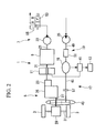
- FIG. 2 A second embodiment of the invention will now be described using FIG. 2 .
- the basic configuration is the same as in the first embodiment, and the configurations of the fork drive portion 7 and the traveling regeneration portion 17 are different. Accordingly, these differences in this embodiment will be described and the description of the other portions will not be repeated.
- FIG. 2 is a block diagram showing a drive portion of the forklift 1.
- the hydraulic pump 33 is directly connected to the engine output shaft 21 and configured to be operated constantly by the engine drive shaft 21.
- An operating oil feeding channel of the hydraulic pump 33 is provided with a switching valve 53.
- the switching valve 53 is configured to switch between a port A connected to an operating oil tank 55 and a port B connected to the hydraulic actuator.
- the traveling regeneration portion 17 is provided with a traveling regeneration clutch (disengaging clutch) 57 instead of the one-way clutch 47 for traveling which is provided in the first embodiment.
- the hydraulic pump 33 is constantly driven by the engine output shaft 21 and supplies the operating oil.
- the switch valve 53 is switched to the port A.
- the operating oil supplied from the hydraulic pump 33 is returned to the operating oil tank 55.
- the switching valve 53 is switched to the port B to supply the operating oil to the hydraulic actuator.
- the traveling regeneration clutch 57 is engaged, and the generator 15 is driven by the traveling drive shaft 27 via the speed-up gear 43 and the traveling regeneration shaft 45.
- the traveling regeneration clutch 57 is disengaged.
- no driving force is supplied to the generator 15 from the traveling regeneration portion 17 during the traveling so that there is corresponding reduction in loss of traveling driving force, but also makes it possible to prevent interference with the hydraulic motor 35 in a reliable manner.
- the traveling regeneration clutch 57 measures the rotational frequency of the speed-up gear 43 and the rotational frequency of the hydraulic motor 35 while the traveling regeneration portion 17 and the work regeneration portion 19 are operating. In a case where the rotational frequency of the speed-up gear 43 is found to be higher, the traveling regeneration clutch 57 is engaged and the generator 15 is driven by the traveling regeneration shaft 45.
- the embodiment is controlled in such a manner that the traveling regeneration clutch 57 is disengaged so that the generator 15 is not driven by the traveling regeneration shaft 45 and the generator 15 is driven by the work regeneration shaft 49 instead.
- the traveling regeneration clutch 57 is provided at the traveling regeneration portion 17 and the one-way clutch 51 for work is provided at the work regeneration portion 19.
- this embodiment may be configured conversely, the disengaging clutch provided at the work regeneration portion 19 and the one-way clutch provided at the traveling regeneration portion 17.
- the embodiment may be configured in such a manner that when the necessity arises, the regenerative energy of the traveling wheel drive portion 5 is introduced to the engine output shaft 21, and electric power is generated by the electric motor 11, which charges the battery 13 by way of the inverter 41.
- FIG. 3 A third embodiment of the invention will now be described using FIG. 3 .
- the basic configuration is the same as in the first embodiment, and the configuration of the traveling regeneration portion 17 is different. Accordingly, these differences in this embodiment will be described and the description of the other portions will not be repeated.
- FIG. 3 is a block diagram showing a drive portion of the forklift 1.
- the traveling regeneration portion 17 of this embodiment is provided with the traveling regeneration clutch 57 and a continuous variable transmission 59 instead of the one-way clutch 47 for traveling of the first embodiment.
- the ability to make the rotational frequency of the traveling regeneration shaft 45 the same as the rotational frequency of the work regeneration shaft 49 allows the generator 15 to be driven constantly by both the traveling regeneration shaft 45 and the work regeneration shaft 49. It is therefore possible to obtain regenerative energy from both and the fuel efficiency can be consequently enhanced.
- the traveling regeneration clutch 57 and the continuous variable transmission 59 are provided at the traveling regeneration portion 17 and the one-way clutch 51 for work is provided at the work regeneration portion 19.
- the embodiment may be configured conversely, the disengaging clutch and a continuous variable transmission being provided at the work regeneration portion 19 and the one-way clutch being provided at the traveling regeneration portion 17.
- the embodiment may be configured in such a manner that when the necessity arises, the regenerative energy of the traveling wheel drive portion 5 is introduced to the engine output shaft 21 and electric power is generated by the electric motor 11 which charges the battery 13 by way of the inverter 41.
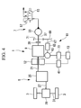
- FIG. 4 A fourth embodiment of the invention will now be described using FIG. 4 .
- the basic configuration is the same as in the first embodiment, and the configuration of the traveling wheel drive portion 5, the configuration of the fork drive portion 7, and the configuration of the regeneration portion are different. Accordingly, these differences in this embodiment will be described and the description of the other portions will not be repeated.
- FIG. 4 is a block diagram showing a drive portion of the forklift 1.
- the torque converter 23 is not used in the traveling wheel drive portion 5. Hence, because the torque multiplying function of the torque converter 23 is absent, it is preferable to use a motor/generator (main motor/generator) 12 type with a higher torque than the electric motor 11 in the first embodiment.
- the motor/generator 12 is directly used for regeneration of the energy of the traveling wheel drive portion 5 and the traveling regeneration portion 17 of the first embodiment is omitted.
- the fork drive portion 7 includes the hydraulic pump motor 33, the work drive shaft 37 to drive the hydraulic pump 33, the clutch 39, the switching valve 53, and a work auxiliary drive portion 61.
- the hydraulic pump 33 is configured so as to receive the operating oil from the port B of the switching valve 53 when the fork is lowered so as to rotate in a direction opposite to the direction when it supplies the operating oil.
- the work auxiliary drive portion 61 includes a work auxiliary motor/generator (auxiliary motor/generator) 63, a work auxiliary one-way clutch (one-way clutch) 65, a work auxiliary shaft (electric motor output shaft) 67, a work auxiliary gear 69, and a work drive shaft gear 71.
- auxiliary motor/generator auxiliary motor/generator
- one-way clutch one-way clutch
- the work drive shaft gear 71 is attached to the work drive shaft 37 between the hydraulic pump 33 and the clutch 39.
- the work auxiliary shaft 67 is the output shaft of the work auxiliary motor/generator 63, and the work auxiliary gear 69 which is meshed with the work drive shaft gear 71 is attached to the end portion of work auxiliary shaft 67.
- the work auxiliary one-way clutch 65 is furnished with a function of transmitting the drive force of the work auxiliary motor/generator 63 to the work auxiliary gear 69 to rotate the work auxiliary gear 69 in a direction in which the hydraulic pump 33 is driving, and on the other hand transmitting the drive force of the work auxiliary gear 69 to the work auxiliary motor/generator 63 in a case where the work auxiliary gear 69 rotates in a direction opposite to the direction specified above, that is, in a case where the hydraulic pump 33 rotates in the opposite direction.
- the work auxiliary motor/generator 63 is connected to the battery 13 via an inverter 73.
- the clutch 39 is disengaged to disconnect the engine output shaft 21 and the work drive shaft 37.
- the engine output shaft 21 is driven rotationally by these components.
- the rotational driving of the engine output shaft 21 is changed by the transmission 25 and transmitted to the traveling drive shaft 27.
- the rotational driving force transmitted to the traveling drive shaft 27 is transmitted to the traveling wheels 3 by way of the differential gear 29 and the front axle 31.
- the driving wheels are thus rotated and forklift 1 travels owing to this rotation.
- the drive force from the engine output shaft 21 is not transmitted to the fork drive portion 7 when the clutch 39 is disengaged. It is thus possible to prevent a loss of energy.
- the work auxiliary motor/generator 63 is driven, and this drives the work drive shaft 37 via the work auxiliary shaft 67, the work auxiliary gear 69, and the work drive shaft gear 71. Consequently, the hydraulic pump 33 is driven, and if the switching valve 53 is switched to the B port, the operating oil is supplied to the (not illustrated) hydraulic actuator and the lift up is performed.
- the clutch 39 is engaged. Because the work drive shaft 37 is connected to the engine output shaft 21 by this engagement, the hydraulic pump 33 is driven by the engine 9 and/or the motor/generator 12 as well as the work auxiliary motor/generator 63. The operating oil is thus supplied to the (not illustrated) hydraulic actuator for the lift up to be performed.
- the engine 9 and/or the motor/generator 12 as well as the work auxiliary motor/generator 63 are driven according to the motive power required for each work. It is therefore sufficient for the motor/generator 12 and the work auxiliary motor/generator 63 to have an output which corresponds to the output of the battery 13 and which together with the engine 9 generates the maximum required driving output.
- the driving force of the motor/generator 12 of this embodiment can be small in comparison with one that drives the traveling wheels 3 or the hydraulic pump 33 independently.
- the structure can be thus downsized.
- the motor/generator 12 is used when the driving output is low, whereas the driving is performed by the engine 9 when the driving force is increased and the driving is performed by the engine 9 and the motor/generator 12 when still more driving force is required.
- the engine 9 be run in a rotational frequency range where the fuel efficiency is high, but also the engine 9 itself can be downsized.
- the work auxiliary motor/generator 63 generates alternating-current electricity as it rotates.
- the alternating-current electricity thus generated is converted to direct-current electricity by the inverter 73 and charged into the battery 13.
- the work auxiliary motor/generator 63 is used for the conversion to electricity in the regeneration of the energy of the fork drive portion 7.
- the energy may be regenerated by changing the state of the operating oil.
- FIG. 5 shows the configuration in which a check valve 75, an accumulator 77, and an on-off valve 79 are provided at the operating oil feeding channel from the hydraulic pump 33, so that the operating oil returned to the hydraulic pump 33 by the lift-down operation is introduced into the accumulator 77 and so kept in pressurized form.
- FIG. 6 and FIG. 7 A fifth embodiment of the invention will now be described using FIG. 6 and FIG. 7 .
- FIG. 6 and FIG. 7 are block diagrams showing a drive portion of the forklift 1.
- the engine output shaft 21 and the work drive shaft 37 are spaced apart and made almost parallel to each other.
- the engine output shaft 21 is provided with an engine output shaft one-way clutch (first one-way clutch) 81 on the engine 9 side.
- An engine output shaft gear 83 is fixed to the engine output shaft 21 between the engine output shaft one-way clutch 81 and the torque converter 23.
- the fork drive portion 7 includes the hydraulic pump 33, the work drive shaft 37, and the switching valve 53.
- a work drive shaft gear 85 meshed with the engine output shaft gear 83 is fixedly attached to the work drive shaft 37.
- the work drive shaft 37 is engaged with a work assist motor/generator (first motor/generator) 87 on the opposite side with respect to the hydraulic pump 33.
- first motor/generator first motor/generator
- the work assist motor/generator 87 is connected to a battery 91 via an inverter 89.
- the driven side gear of the speed-up gear 43 is engaged with a traveling assist motor/generator (second motor/generator) 93.
- the traveling assist motor/generator 93 is gear-coupled to the traveling drive shaft 27 by the speed-up gear 43.
- the traveling assist motor/generator 93 is connected to the battery 91 via an inverter 95.
- the traveling assist motor/generator 93 is configured so as to drive the traveling drive shaft 27 via the speed-up gear 43 or to be rotated by the traveling drive shaft 27 via the speed-up gear and thus generate electric power.
- a hydraulic motor output shaft gear 99 is fixedly attached to the rotation shaft of the hydraulic motor 35 via a hydraulic motor one-way clutch (second one-way clutch) 97.
- the hydraulic motor output shaft gear 99 is meshed with the engine output shaft gear 83.
- the hydraulic motor one-way clutch 97 and the hydraulic motor output shaft gear 99 form the work regeneration portion 19.
- the forklift 1 travels to a cargo while the fork is lowered and stops after it inserts the fork beneath the cargo.
- the forklift 1 is moved so as to pull out the fork from beneath the cargo and headed for a next work.
- the traveling wheels 3 repeat the cycle of start, acceleration, traveling at a constant speed, deceleration, and stop, and the fork repeats a cycle of stop, lift up, and lift down.
- the cargo handling work by the forklift 1 is performed as these operations are combined.
- the traveling wheel drive portion 5 is driven by the traveling assist motor/generator 93 and the work assist motor/generator 87 whose energy efficiency remains the same when rotational frequency is low.
- the work assist motor/generator 87 When the alternating-current electricity is supplied to the work assist motor/generator 87 from the battery 91 via the inverter 89, the work assist motor/generator 87 is driven rotationally. This rotational driving then rotationally drives the engine output shaft 21 by way of the work drive shaft 37, the work drive shaft gear 85, and the engine output shaft gear 83.
- the rotational driving of the engine output shaft 21 is changed by the transmission 25 and transmitted to the traveling drive shaft 27.
- the hydraulic pump 33 is driven by the rotation of the work drive shaft 37.
- the switching valve 53 is switched to the port A, the operating oil is only returned to the operating oil tank 55 even when the hydraulic pump 33 is driven. Hence, there is no significant loss of power.
- the engine output shaft one-way clutch 81 is present between the work drive shaft 37 and the engine 9, even when the work assist motor/generator 87 (engine output shaft 21) rotates, this rotation will not rotationally drive the engine 9.
- the engine output shaft one-way clutch 81 is capable of preventing the engine 9 from becoming a resisting force against the driving by the work assist motor/generator 87.
- the hydraulic motor output shaft gear 99 is driven by the engine output shaft gear 83.
- the hydraulic motor one-way clutch 97 is present, the rotational driving force will not be transmitted to the hydraulic motor 35.
- the traveling assist motor/generator 93 When the alternating-current electricity is supplied to the traveling assist motor/generator 93 from the battery 91 via the inverter 95, the traveling assist motor/generator 93 is driven rotationally. This rotational driving then rotationally drives the traveling drive shaft 27 via the speed-up gear 43.
- the engine 9 is driven because the rotational frequency becomes higher and a large driving force is required.
- the rotational frequency is increased quickly by driving the engine 9.
- the rotational frequency of the engine 9 becomes higher than the rotational frequency of the engine output shaft 21 by the work assist motor/generator 87, the driving force of the engine 9 is added to the engine output shaft 21 through the engine output shaft one-way clutch 81.
- the switching valve 53 is switched to the port B, as is shown in Fig. 7 .
- the work assist motor/generator 87 is directly connected to the hydraulic pump 33 and the engine 9 is connected thereto via the engine rotation shaft 21, the engine output shaft gear 83, and the work drive shaft gear 85.
- the driving is performed by the engine 9, the traveling assist motor/generator 93, and/or the work assist motor/generator 87 according to the motive power required for the traveling and for the cargo handling work. It is therefore sufficient for the traveling assist motor/generator 93 and the work assist motor/generator 87 to have an output which corresponds to the output of the battery 91 and which together with the engine 9 generates the maximum required driving output.
- the driving power of the traveling assist motor/generator 93 and of the work assist motor/generator 87 can be small in this embodiment in comparison with those that drive the traveling wheels 3 or the hydraulic pump 33 independently.
- the structure can be thus downsized.
- the traveling assist motor/generator 93 and the work assist motor/generator 87 are used when driving output is low, whereas the driving is performed by the engine 9 when the driving force is increased and the driving is performed by the engine 9, the traveling assist motor/generator 93, and the work assist motor/generator 87 when still more driving force is required.
- the engine 9 be run in a rotational frequency range where the fuel efficiency is high, but also the engine 9 itself can be downsized.
- the forward-reverse clutch of the transmission 25 is shifted to the neutral position, so that the driving force from the traveling drive shaft 27 is not introduced to the transmission 25.
- the driving force of the traveling drive shaft 27 is transmitted to the traveling assist motor/generator 93 by way of the speed-up gear 43, rotationally driving the output shaft of the traveling assist motor/generator 93.
- the traveling assist motor/generator 93 When the output shaft is rotated, the traveling assist motor/generator 93 generates alternating-current electricity.
- the alternating-current electricity thus generated is converted to direct-current electricity by the inverter 95 and charged into the battery 91.
- the hydraulic motor 35 is driven rotationally by the operating oil returning from the hydraulic actuator.
- Rotation of the hydraulic motor 35 is transmitted to the work drive shaft 37 by way of the hydraulic motor output shaft gear 99, the engine output shaft gear 83, and the work drive shaft gear 85, and rotationally drives the output shaft of the work assist motor/generator 87.
- the work assist motor/generator 87 When the output shaft is rotated, the work assist motor/generator 87 generates alternating-current electricity.
- the alternating-current electricity thus generated is converted to the direct-current electricity by the inverter 89 and charged into the battery 91.
- the engine output shaft gear 83 is present in the transmission channel from the hydraulic motor 35, for example, when the rotational frequency of the hydraulic motor 35 is reduced below the rotational frequency of the engine 9, the engine 9 rotates the work assist motor/generator 87. Regeneration from the hydraulic motor 35 thus ends.
- the regenerative energy of the traveling wheel drive portion 5 is collected into the traveling assist motor/generator 93 whereas the regenerative energy of the fork drive portion 7 is collected separately, into the work assist motor/generator 87, it is possible to prevent interference of the portions with each other in a reliable manner.
- the traveling assist motor/generator 93 and the work assist motor/generator 87 are driven by the single battery 91 commonly. However, each may be provided with an exclusive-use battery.
- FIG. 8 A sixth embodiment of the invention will now be described using FIG. 8 .
- the basic configuration is the same as in the fifth embodiment and configurations of the fork drive portion 7 and the work regeneration portion 19 are different. Accordingly, these differences in this embodiment will be described and the description of the other portions will not be repeated.
- FIG. 8 is a block diagram showing a drive portion of the forklift 1.
- the traveling regeneration portion 17 includes a traveling battery 101 that drives the traveling assist motor/generator 93.
- the engine output shaft 21 penetrates through the engine 9 so that it extends from both sides.
- the fork drive portion 7 is of almost the same configuration as in the fourth embodiment.
- the work drive shaft 37 is disposed so as to form the extended portion of the engine output shaft 21, and these two shafts are connected by the clutch 39 in a disconnectable manner.
- the work drive shaft gear 71 is attached to the portion of the work drive shaft 37 toward the clutch 39.
- the work assist motor/generator 87 is driven by a work battery 103.
- the rotation shaft 105 of the work assist motor/generator 87 is configured so as to drive a rotation shaft gear 109 which is meshed with the work drive shaft gear 71, by way of a rotation shaft one-way clutch (second one-way clutch) 107.
- the traveling wheel drive portion 5 is driven by the traveling assist motor/generator 93 whose energy efficiency remains the same when the rotational frequency is low.
- the traveling assist motor/generator 93 When the alternating-current electricity is supplied to the traveling assist motor/generator 93 from the battery 101 via the inverter 95, the traveling assist motor/generator 93 is driven rotationally. This in turn rotationally drives the traveling drive shaft 27 via the speed-up gear 43.
- the clutch 39 is engaged to connect the engine output shaft 21 and the work drive shaft 37 and introduce the driving force of the work assist motor/generator 87 to the engine output shaft 21.
- the alternating-current electricity is supplied to the work assist motor/generator 87 from the battery 103 via the inverter 89, the work assist motor/generator 87 is rotated. This then rotationally drives the engine output shaft 21 by way of the output shaft gear 109, the work drive shaft gear 71, the work drive shaft 37, and the clutch 39.
- the rotational driving of the engine output shaft 21 is changed by the transmission 25 and transmitted to the traveling drive shaft 27.
- the hydraulic pump 33 is driven by the rotation of the work drive shaft 37.
- the switching valve 53 is switched to the port A, the operating oil is only returned to the operating oil tank 55 even when the hydraulic pump 33 is driven. Hence, there is no significant loss of power.
- the engine 9 does not have to be driven in a case where the rotational frequency is low, the operation efficiency of the engine 9 will not be deteriorated.
- the driving force of the engine output shaft 21 is increased by driving the engine 9 because the rotational frequency becomes higher and a large driving force is required.
- the switching valve 53 is switched to the port B.
- the operating oil is supplied to the (not illustrated) hydraulic actuator by passing through the port B of the switching valve 53 and, for example, the lift up is performed.
- the driving is performed by the engine 9, the traveling assist motor/generator 93, and/or the work assist motor/generator 87 according to the motive power required for the traveling and for the cargo handling. It is therefore sufficient for the traveling assist motor/generator 93 and the work assist motor/generator 87 to have an output which corresponds to the output of the battery 91 and which together with the engine 9 generates the maximum required driving output.
- the driving force of the traveling assist motor/generator 93 and of the work assist motor/generator 87 in this embodiment can be small in comparison with those that drive the traveling wheels 3 or the hydraulic pump 33 independently.
- the structure can be thus downsized.
- the traveling assist motor/generator 93 and the work assist motor/generator 87 are used when the driving force output is low, whereas the driving is performed by the engine 9 when the driving force is increased and the driving is performed by the engine 9, the traveling assist motor/generator 93, and the work assist motor/generator 87 when still more driving force is required.
- the engine 9 be run in a rotational frequency range where the fuel efficiency is high, but also the engine 9 itself can be downsized.
- the forward-reverse clutch of the transmission 25 is shifted to the neutral position, so that the driving force from the traveling drive shaft 27 is not introduced to the transmission 25.
- the driving force of the traveling drive shaft 27 is transmitted to the traveling assist motor/generator 93 by way of the speed-up gear 43 to rotationally drive the output shaft of the traveling assist motor/generator 93.
- the traveling assist motor/generator 93 When the output shaft is rotated, the traveling assist motor/generator 93 generates alternating-current electricity.
- the alternating-current electricity thus generated is converted to direct-current electricity by the inverter 95 and charged into the battery 101.
- the hydraulic pump 33 is driven rotationally by the operating oil returning from the hydraulic actuator by way of the switching valve 53.
- the clutch 39 is disengaged.
- Rotation of the hydraulic pump 33 is transmitted by way of the work drive shaft 37, the work drive shaft gear 71, and the output shaft gear 109, and rotationally drive the output shaft of the work assist motor/generator 87.
- the work assist motor/generator 87 When the output shaft is rotated, the work assist motor/generator 87 generates alternating-current electricity. The alternating-current electricity thus generated is converted to the direct-current electricity by the inverter 89 and charged into the battery 103.
- the work assist motor/generator 87 can be driven by the engine 9 if the clutch 39 is engaged, it is possible to charge the battery 91 without any loss by switching the switching valve 53 to the port A.
- the regenerative energy of the traveling wheel drive portion 5 is collected in the traveling assist motor/generator 93 and the regenerative energy of the fork drive portion 7 is separately collected, in the work assist motor/generator 87. It is thus possible to prevent the interference of the portions with each other in a reliable manner.
- the embodiment may be configured in such a manner that the traveling assist motor/generator 93 and the work assist motor/generator 87 are driven by a single common battery.
- FIG. 9 A seventh embodiment of the invention will now be described using FIG. 9 .
- This embodiment is of a configuration similar to that of the fifth embodiment, and the configuration of the vehicle drive portion 5 and the configuration of the traveling regeneration portion 17 are different. Accordingly, these differences in this embodiment will be described and the description of the other portions will not be repeated.
- FIG. 9 is a block diagram showing a drive portion of the forklift 1.
- a hydraulic transmission (fluid transmission) 111 is used in the vehicle drive portion 5.
- the hydraulic transmission 111 includes a swash-plate type hydraulic pump 113 driven by the engine output shaft 21, a hydraulic motor 115 driven by the hydraulic pump 113, and hydraulic tubes 117 and 119 connecting the hydraulic pump 113 and the hydraulic motor 115.
- the traveling drive shaft 27 is connected to the output portion of the hydraulic motor 115 so as to rotate together with rotation of the hydraulic motor 115.
- the hydraulic pump 113 is provided with a swash plate 121 and it is configured in such a manner that the hydraulic pump 113 behaves differently according to the inclination of the swash plate 121.
- the hydraulic pump 113 sends the oil toward the hydraulic tube 117 to generate a circulation flow for collecting the oil from the hydraulic tube 119.
- the inclination angle of the inclination B is increased with respect to the inclination A.
- the flow rate of the oil increases as the inclination becomes larger, which increases the rotation speed of the hydraulic motor 115.
- the hydraulic pump 113 sends the oil toward the hydraulic tube 119 to form a circulation flow for collecting the oil from the hydraulic tube 117.
- the traveling drive shaft 27 thus rotates in a direction opposite to the direction when the inclination is at B.
- the inclination angle of the inclination C is increased with respect to the inclination A.
- the flow rate of the oil increases as the inclination becomes larger, which increases the rotation speed of the hydraulic motor 115.
- the hydraulic transmission 111 is capable of shifting the rotation of the traveling drive shaft to stop (neutral), forward rotation, and reverse rotation according to the inclinations of the swash plate 121.
- transmission loss is less than where many transmission portions, such as the torque converter 23 and the transmission 25, are present, it is possible to enhance the driving force transmission efficiency.
- the hydraulic motor 115 When the hydraulic motor 115 is operated by the traveling drive shaft 27, the hydraulic motor 115 functions as the hydraulic pump and a circulation flow is formed. Accordingly, the hydraulic pump 113 functions as the hydraulic motor and is thereby rotated, which causes the engine output shaft 21 to rotate.
- the engine output shaft 21 is rotated in this manner. However, because the engine output shaft one-way clutch 81 is present, this rotation will not be transmitted to the engine 9.
- the assist motor/generator (auxiliary motor/generator) 123 is rotated via the work drive shaft gear 85.
- the traveling drive shaft is rotated by the regenerative energy of the traveling wheel drive portion 5
- the regenerative energy can be collected by the assist motor/generator 123 via the hydraulic transmission 111.
- the speed-up gear 43, the traveling assist motor/generator 93, and the inverter 95 for the traveling regeneration portion 17 provided in the fifth embodiment are therefore omitted in this embodiment.
- the hydraulic transmission 111 is capable of transmitting the energy in the reverse direction
- the configuration of the traveling regeneration portion can be made much more simple, which can in turn reduce the overall weight. The fuel efficiency can be therefore enhanced.
- the forklift 1 travels to a cargo while the fork is lowered and stops after it inserts the fork beneath the cargo.
- the forklift 1 is moved so as to pull out the fork from beneath the cargo and then heads for the next work.
- the traveling wheels 3 repeat a cycle of start, acceleration, traveling at a constant speed, deceleration, and stop, and the fork repeats a cycle of stop, lift up, and lift down.
- the cargo handling work performed by the forklift 1 is a combination of these operations. Hereinafter, an example of these operations will be described.
- the traveling wheel drive portion 5 is driven by the assist motor/generator 123 whose energy efficiency remains the same when rotational frequency is low.
- the assist motor/generator 123 When the alternating-current electricity is supplied to the assist motor/generator 123 from the battery 91 via the inverter 89, the assist motor/generator 123 is driven rotationally. This rotational driving then rotationally drives the engine output shaft 21 by way of the work drive shaft 37, the work drive shaft gear 85, and the engine output shaft gear 83.
- the rotational driving force of the engine output shaft 21 is changed or adjusted by the hydraulic transmission 111 and transmitted to the traveling drive shaft 27.
- the hydraulic pump 33 is driven by rotation of the work drive shaft 37.
- the switching valve 53 is switched to the port A, the operating oil is only returned to the operating oil tank 55 even when the hydraulic pump 33 is driven. Hence, there will be no significant loss of power.
- the engine output shaft one-way clutch 81 is present between the work drive shaft 37 and the engine 9, even when the assist motor/generator 123 (engine output shaft 21) rotates, the engine 9 will not be driven rotationally.
- the engine output shaft one-way clutch 81 is capable of preventing the engine 9 from resisting the driving of the assist motor/generator 123.
- the hydraulic motor output shaft gear 99 is driven by the engine output shaft gear 83.
- the hydraulic motor one-way clutch 97 is present, the rotational driving force will not be transmitted to the hydraulic motor 35.
- the engine 9 is driven because the rotational frequency becomes higher and a large driving force is required.
- the rotational frequency is increased quickly by driving the engine 9.
- the rotational frequency of the engine 9 becomes higher than the rotational frequency of the engine output shaft 21 driven by the assist motor/generator 123, the driving force of the engine 9 is added to the engine output shaft 21 through the engine output shaft one-way clutch 81.
- the switching valve 53 is switched to the port B.
- the assist motor/generator 123 is directly connected to the hydraulic pump 33 and the engine 9 is connected thereto via the engine rotation shaft 21, the engine output shaft gear 83, and the work drive shaft gear 85.
- the driving is performed by the engine 9 and/or the assist motor/generator 123 according to the motive power required for the traveling and for the cargo handling work.
- the assist motor/generator 123 it is therefore sufficient for the assist motor/generator 123 to have an output which corresponds to the output of the battery 91 and which together with the engine 9 generates the maximum required driving output.
- the driving force of the assist motor/generator 123 of this embodiment can be small in comparison with one that drives the traveling wheels 3 or the hydraulic pump 33 independently.
- the structure can be thus downsized.
- the assist motor/generator 123 is used when driving force output is low, whereas the driving is performed by the engine 9 when the driving force is increased and the driving is performed by the engine 9 and the assist motor/generator 123 when still more driving force is required.
- the engine 9 be run in a rotational frequency range where the fuel efficiency is high, but also the engine 9 itself can be downsized.
- the driving force of the traveling drive shaft 27 drives the hydraulic motor 115.
- the hydraulic motor 115 rotates, oil flows into the hydraulic tube 117 or the hydraulic tube 119 to rotate the hydraulic pump 113.
- the engine output shaft 21 is therefore rotated.
- the assist motor/generator 123 When the engine output shaft 21 rotates, because the assist motor/generator 123 is rotated via the engine output gear 83 and the work drive shaft gear 85, the assist motor/generator 123 generates alternating-current electricity. The alternating-current electricity thus generated is converted to direct-current electricity by the inverter 89 and charged into the battery 91.
- Rotation of the hydraulic motor 35 is transmitted to the work drive shaft 37 by way of the hydraulic motor output shaft gear 99, the engine output shaft gear 83, and the work drive shaft gear 85, and work drive shaft 37 rotationally drives the output shaft of the assist motor/generator 123.
- the assist motor/generator 123 When the output shaft is rotated, the assist motor/generator 123 generates alternating-current electricity. The alternating-current electricity thus generated is converted to the direct-current electricity by the inverter 89 and charged into the battery 91.
- FIG. 10 An eighth embodiment of the invention will now be described using FIG. 10 .
- This embodiment is of a configuration similar to that of the seventh embodiment, and the configuration of the fork drive portion 7 is different. Accordingly, these differences in this embodiment will be described and the description of the other portions will not be repeated.
- FIG. 10 is a block diagram showing a drive portion of the forklift 1.
- the hydraulic tube 117 includes a drive-use three-way valve (switching valve for work) 125.
- the drive-use three-way valve 125 communicates at one end with a hydraulic tube 127 that supplies the operating oil to the hydraulic actuator driving the fork, the actuator being for example a hydraulic cylinder.
- the drive-use three-way valve 125 selects whether the oil from the hydraulic pump 113 is introduced into the hydraulic motor 115 or into the hydraulic tube 127 that supplies the oil to the hydraulic actuator for driving the fork.
- the fork drive portion 7 is simplified markedly, the overall weight can be further lessened. The fuel efficiency can therefore be further enhanced.
- the traveling wheel drive portion 5 is driven by the assist motor/generator 123 whose energy efficiency remains the same when rotational frequency is low.
- the assist motor/generator 123 When the alternating-current electricity is supplied to the assist motor/generator 123 from the battery 91 via the inverter 89, the assist motor/generator 123 is rotated. This rotational driving then rotationally drives the engine output shaft 21 by way of the work drive shaft 37, the work drive shaft gear 85, and the engine output shaft gear 83.
- the rotational driving of the engine output shaft 21 is changed or adjusted by the hydraulic transmission 111 and transmitted to the traveling drive shaft 27.
- the drive-use three-way valve 125 is connected to the port that brings the hydraulic pump 113 and the hydraulic motor 115 into communication.
- the engine output shaft one-way clutch 81 is present between the work drive shaft 37 and the engine 9, even when the assist motor/generator 123 (engine output shaft 21) rotates, the engine 9 will not be rotated.
- the engine output shaft one-way clutch 81 is capable of preventing the engine 9 from resisting the driving of the assist motor/generator 123.
- the hydraulic motor output shaft gear 99 is driven by the engine output shaft gear 83.
- the hydraulic motor one-way clutch 97 is present, the rotational driving force will not be transmitted to the hydraulic motor 35.
- the engine 9 is driven because the rotational frequency becomes higher and a large driving force is required.
- the rotational frequency is increased quickly by driving the engine 9.
- the rotational frequency of the engine 9 becomes higher than the rotational frequency of the engine output shaft 21 driven by the assist motor/generator 123, the driving force of the engine 9 is added to the engine output shaft 21 through the engine output shaft one-way clutch 81.
- the drive-use three-way valve 125 is switched to introduce the oil into the hydraulic tube 127, and the swash plate 121 is moved to inclination B.
- the oil from the hydraulic pump 113 flows into the hydraulic tube 127 via the hydraulic tube 117 and the drive-use three-way valve 125.
- the fork is thus raised (lift-up).
- the engine output shaft 21 is driven by the assist motor/generator 123 and/or the engine 9.
- the driving is performed by the engine 9 and/or the assist motor/generator 123 according to the motive power required for the traveling and for the cargo handling work.
- the assist motor/generator 123 it is therefore sufficient for the assist motor/generator 123 to have an output which corresponds to the output of the battery 91 and which together with the engine 9 generates the maximum required driving output.
- a driving force of the assist motor/generator 123 of this embodiment can be small in comparison with one that drives the traveling wheels 3 or the fork independently.
- the structure can be thus downsized.
- the assist motor/generator 123 is used when driving force output is low, whereas the driving is performed by the engine 9 when the driving force is increased and the driving is performed by the engine 9 and the assist motor/generator 123 when still more driving force is required.
- the engine 9 be fun in a rotational frequency range where the fuel efficiency is high, but also the engine 9 itself can be downsized.
- the driving force of the traveling drive shaft 27 drives the hydraulic motor 115.
- the hydraulic motor 115 rotates, the oil flows into the hydraulic tube 117 or the hydraulic tube 119 to rotate the hydraulic pump 113.
- the engine output shaft 21 is therefore rotated.
- the assist motor/generator 123 When the engine output shaft 21 rotates, the assist motor/generator 123 is rotated via the engine output gear 83 and the work drive shaft gear 85. The assist motor/generator 123 therefore generates alternating-current electricity. The alternating-current electricity thus generated is converted to direct-current electricity by the inverter 89 and charged into the battery 91.
- the hydraulic motor 35 is driven rotationally by the operating oil returning from the hydraulic actuator.
- Rotation of the hydraulic motor 35 is transmitted to the work drive shaft 37 by way of the hydraulic motor output shaft gear 99, the engine output shaft gear 83, and the work drive shaft gear 85 and the work drive shaft 37 rotationally drives the output shaft of the assist motor/generator 123.
- the assist motor/generator 123 When the output shaft is rotated, the assist motor/generator 123 generates alternating-current electricity. The alternating-current electricity thus generated is converted to the direct-current electricity by the inverter 89 and charged into the battery 91.
- FIG. 11 A ninth embodiment of the invention will now be described using FIG. 11 .
- This embodiment is of a configuration similar to that of the eighth embodiment and the configuration of the work regeneration portion 19 is different. Accordingly, these differences in this embodiment will be described and the description of the other portions will not be repeated.
- the same components as in the eighth embodiment are labeled with the same numbers, and a detailed description of such components is omitted here.
- FIG. 11 is a block diagram showing a drive portion of the forklift 1.
- the work regeneration portion 19 in this embodiment will be described.
- the hydraulic tube 117 includes a regeneration-use three-way valve 129 on the hydraulic motor 115 side of the drive-use three-way valve 125.
- the regeneration-use three-way valve 129 communicates at one end with a hydraulic tube 131 for the operating oil returning from the hydraulic actuator driving the fork, the actuator being for example a hydraulic cylinder.
- the regeneration-use three-way valve 129 selects whether the hydraulic pump 113 communicates with the hydraulic motor 115, or with the hydraulic tube 131 by which oil returns from the actuator that drives the fork.
- the traveling drive shaft 27 is provided with a clutch 133 that disconnects and connects, and a traveling drive shaft gear 135 attached between the clutch 133 and the hydraulic motor 115.
- a motor/generator 137 for regeneration is provided in such a manner that a regeneration gear 139 attached to the output shaft of motor/generator 137 is meshed with the traveling drive shaft gear 135.
- the motor/generator 137 for regeneration is connected to the battery 91 via an inverter 141.
- the hydraulic motor 115 of this embodiment includes a swash plate 143 that switches between forward and reverse rotation.
- the traveling wheel drive portion 5 is driven by the assist motor/generator 123 whose energy efficiency remains the same when rotational frequency is low.
- the assist motor/generator 123 When the alternating-current electricity is supplied to the assist motor/generator 123 from the battery 91 via the inverter 89, the assist motor/generator 123 is rotated. This rotational driving then rotationally drives the engine output shaft 21 by way of the work drive shaft 37, the work drive shaft gear 85, and the engine output shaft gear 83.
- the rotational driving of the engine output shaft 21 is changed or adjusted by the hydraulic transmission 111 and transmitted to the traveling drive shaft 27 to which the clutch 133 is connected.
- the drive-use three-way valve 125 and the regeneration-use three-way valve 129 are switched to the respective ports that bring the hydraulic pump 113 and the hydraulic motor 115 into communication.
- the engine 9 does not have to be driven in a case where the rotational frequency is low, the operation efficiency of the engine 9 will not be deteriorated.
- the engine output shaft one-way clutch 81 is present between the hydraulic pump 113 and the engine 9, even when the assist motor/generator 123 (engine output shaft 21) rotates, the engine 9 will not be driven rotationally.
- the engine output shaft one-way clutch 81 is capable of preventing the engine 9 from resisting the driving of the assist motor/generator 123.
- the engine 9 is driven because the rotational frequency becomes higher and a large driving force is required.
- the rotational frequency is increased quickly by driving the engine 9.
- the rotational frequency of the engine 9 becomes higher than the rotational frequency of the engine output shaft 21 driven by the assist motor/generator 123, the driving force of the engine 9 is added to the engine output shaft 21 through the engine output shaft one-way clutch 81.
- the traveling drive shaft 27 may be driven rotationally via the regeneration gear 139 and the traveling drive shaft gear 135 by rotationally driving the motor/generator 137 for regeneration.
- the drive-use three-way valve 125 is switched to introduce the oil into the hydraulic tube 127, and the swash plate 121 is moved to the inclination B.
- the engine output shaft 21 is driven by the assist motor/generator 123 and/or the engine 9.
- the driving is performed by the engine 9, the assist motor/generator 123, and/or the motor/generator 137 for regeneration according to the motive power required for traveling and for the cargo handling work. It is therefore sufficient for the assist motor/generator 123 and the motor/generator 137 for regeneration to have an output which corresponds to the output of the battery 91 and which together with the engine 9 generates the maximum required driving output.
- driving forces of the assist motor/generator 123 and the motor/generator 137 for regeneration in this embodiment can be small in comparison with those that drive the traveling wheels 3 or the fork independently.
- the structure can be thus downsized.
- the assist motor/generator 123 is used when driving force output is low, whereas the driving is performed by the engine 9 when the driving force is increased, and the driving is performed by the engine 9 and the assist motor/generator 123 when still more driving force is required.
- the engine 9 be run in a rotational frequency range where the fuel efficiency is high, but also the engine 9 itself can be downsized.
- the driving force of the traveling drive shaft 27 rotates the motor/generator 137 for regeneration by way of the traveling drive shaft gear 135 and the regeneration gear 139.
- the motor/generator 137 for regeneration therefore generates alternating-current electricity.
- the alternating-current electricity thus generated is converted to the direct-current electricity by the inverter 141 and charged into the battery 91.
- regenerated energy may be collected by rotationally driving the assist motor/generator 123 by way of the hydraulic transmission 111 in the same manner as in the eighth embodiment.
- the swash plate 121 of the hydraulic pump 113 is positioned at neutral (inclination A), so that no pumping will be performed.
- the clutch 133 is disengaged to disconnect the hydraulic motor 115 and the traveling wheel drive portion 5.
- the swash plate 143 of the hydraulic motor 115 is inclined for reverse travel.
- the regeneration-use three-way valve 129 is switched so as to communicate with the hydraulic circuit 131.
- the oil flows into the hydraulic motor 115 from the hydraulic tube 131 via the regeneration-use three-way valve 129.
- the hydraulic motor 115 is driven rotationally by the flow of the oil, which causes the traveling drive shaft 27 connected to the hydraulic motor 115 side to rotate.
- the motor/generator 137 for regeneration When the traveling drive shaft 27 rotates, the motor/generator 137 for regeneration is rotated via the traveling drive shaft gear 135 and the regeneration gear 139. The motor/generator 137 for regeneration therefore generates alternating-current electricity.
- the alternating-current electricity thus generated is converted to direct-current electricity by the inverter 141 and charged into the battery 91.
- FIG. 12 A tenth embodiment of the invention will now be described using FIG. 12 .
- This embodiment is of a configuration similar to that of the seventh embodiment and the position where the hydraulic transmission 111 is provided is different. Accordingly, this difference in this embodiment will be described and the description of the other portions will not be repeated.
- FIG. 12 is a block diagram showing a drive portion of the forklift 1.
- the hydraulic pump 113 of the hydraulic transmission 111 is connected to the engine output shaft 21, and no component is interposed between the hydraulic pump 113 and the engine 9.
- traveling drive shaft 27 In the traveling drive shaft 27 is provided the traveling drive shaft gear 135.
- the work regeneration portion 19, the fork drive portion 7, and the assist motor/generator 123 that are engaged with the engine output shaft gear 83 in the seventh embodiment are engaged with the traveling drive shaft gear 135 in this embodiment.
- the hydraulic transmission 111 carries out the function of the engine output shaft one-way clutch 81 used in the seventh embodiment.
- the hydraulic transmission 111 is used as an alternative component carrying out the function of the engine output shaft one-way clutch 81 which has high sensitivity to vibration. This eliminates the need to use a one-way clutch having high sensitivity to vibration. The safety of the entire device can be thus enhanced.
- the traveling wheel drive portion 5 is driven by the assist motor/generator 123 whose energy efficiency remains the same when rotational frequency is low.
- the assist motor/generator 123 When the alternating-current electricity is supplied to the assist motor/generator 123 from the battery 91 via the inverter 89, the assist motor/generator 123 is driven rotationally. This rotational driving then rotationally drives the traveling drive shaft 27 by way of the work drive shaft 37, the work drive shaft gear 85, and the traveling drive shaft gear 135.
- the hydraulic motor output shaft gear 99 is driven by the traveling drive shaft gear 135.
- the hydraulic motor one-way clutch 97 is present, the rotational driving force will not transmitted to the hydraulic motor 35.
- the engine 9 is driven because the rotational frequency becomes higher and a large driving force is required.
- the rotational frequency is increased quickly by driving the engine 9.
- the driving force of the engine 9 is added to the traveling drive shaft 27 by adjusting the inclination of the swash plate 121 of the hydraulic transmission 111 or the like.
- the switching valve 53 is switched to the port B.
- the assist motor/generator 123 is directly connected to the hydraulic pump 33 and the engine 9 is connected thereto via the engine rotation shaft 21, the hydraulic transmission 111, the traveling drive shaft 27, the traveling drive shaft gear 135, and the work drive shaft gear 85.
- the traveling drive shaft 27 is driven by the assist motor/generator 123 and the engine 9.
- the driving is performed by the engine 9 and/or the assist motor/generator 123 according to the motive power required for the traveling and for the cargo handling work.
- the assist motor/generator 123 it is therefore sufficient for the assist motor/generator 123 to have an output which corresponds to the output of the battery 91 and which together with the engine 9 generates the maximum required driving output.
- the driving force of the assist motor/generator 123 of this embodiment can be small in comparison with one that drives the traveling wheels 3 or the fork independently.
- the structure can be thus downsized.
- the assist motor/generator 123 is used when driving force output is low, whereas the driving is performed by the engine 9 when the driving force is increased and the driving is performed by the engine 9 and the assist motor/generator 123 when still more driving force is required.
- the engine 9 be run in a rotational frequency range where the fuel efficiency is high, but also the engine 9 itself can be downsized.
- the assist motor/generator 123 Because the driving force of the traveling drive shaft 27 rotationally drives the assist motor/generator 123 via the traveling drive shaft gear 135 and the work drive shaft gear 85, the assist motor/generator 123 generates alternating-current electricity.
- the alternating-current electricity thus generated is converted to direct-current electricity by the inverter 89 and charged into the battery 91.
- the hydraulic motor 35 is driven rotationally by the operating oil returning from the hydraulic actuator.
- Rotation of the hydraulic motor 35 is transmitted to the work drive shaft 37 by way of the hydraulic motor output shaft gear 99, the traveling drive shaft gear 135, and the work drive shaft gear 85, and the work drive shaft 37 rotationally drives the output shaft of the work assist motor/generator 123.
- the assist motor/generator 123 When the output shaft is rotated, the assist motor/generator 123 generates alternating-current electricity. The alternating-current electricity thus generated is converted to the direct-current electricity by the inverter 89 and charged into the battery 91.
Landscapes
- Engineering & Computer Science (AREA)
- Transportation (AREA)
- Chemical & Material Sciences (AREA)
- Combustion & Propulsion (AREA)
- Mechanical Engineering (AREA)
- Structural Engineering (AREA)
- Civil Engineering (AREA)
- Geology (AREA)
- Life Sciences & Earth Sciences (AREA)
- Mining & Mineral Resources (AREA)
- General Engineering & Computer Science (AREA)
- Hybrid Electric Vehicles (AREA)
- Electric Propulsion And Braking For Vehicles (AREA)
- Forklifts And Lifting Vehicles (AREA)
- Operation Control Of Excavators (AREA)
- Arrangement And Driving Of Transmission Devices (AREA)
Applications Claiming Priority (3)
| Application Number | Priority Date | Filing Date | Title |
|---|---|---|---|
| JP2006150378 | 2006-05-30 | ||
| JP2006303783A JP4052483B2 (ja) | 2006-05-30 | 2006-11-09 | 作業車両 |
| EP07743498.3A EP2022748A4 (de) | 2006-05-30 | 2007-05-16 | Nutzfahrzeug |
Related Parent Applications (1)
| Application Number | Title | Priority Date | Filing Date |
|---|---|---|---|
| EP07743498.3A Division EP2022748A4 (de) | 2006-05-30 | 2007-05-16 | Nutzfahrzeug |
Publications (2)
| Publication Number | Publication Date |
|---|---|
| EP2687477A1 true EP2687477A1 (de) | 2014-01-22 |
| EP2687477B1 EP2687477B1 (de) | 2016-08-24 |
Family
ID=38778382
Family Applications (2)
| Application Number | Title | Priority Date | Filing Date |
|---|---|---|---|
| EP13189434.7A Active EP2687477B1 (de) | 2006-05-30 | 2007-05-16 | Nutzfahrzeug |
| EP07743498.3A Withdrawn EP2022748A4 (de) | 2006-05-30 | 2007-05-16 | Nutzfahrzeug |
Family Applications After (1)
| Application Number | Title | Priority Date | Filing Date |
|---|---|---|---|
| EP07743498.3A Withdrawn EP2022748A4 (de) | 2006-05-30 | 2007-05-16 | Nutzfahrzeug |
Country Status (5)
| Country | Link |
|---|---|
| US (1) | US8167078B2 (de) |
| EP (2) | EP2687477B1 (de) |
| JP (1) | JP4052483B2 (de) |
| KR (1) | KR20080098060A (de) |
| WO (1) | WO2007138862A1 (de) |
Families Citing this family (34)
| Publication number | Priority date | Publication date | Assignee | Title |
|---|---|---|---|---|
| JP4284335B2 (ja) * | 2006-06-01 | 2009-06-24 | 株式会社竹内製作所 | 作業用車両 |
| GB2447229B (en) * | 2007-03-07 | 2011-11-02 | Niftylift Ltd | Mobile work platform with multiple mode drive system |
| US8360180B2 (en) * | 2007-12-31 | 2013-01-29 | Caterpillar Inc. | System for controlling a hybrid energy system |
| JP5386479B2 (ja) * | 2008-03-27 | 2014-01-15 | ニチユ三菱フォークリフト株式会社 | ハイブリッド型産業車両 |
| JP5010555B2 (ja) * | 2008-08-25 | 2012-08-29 | 三菱重工業株式会社 | ハイブリッド型産業車両のインチングペダルシステム |
| JP2010052493A (ja) * | 2008-08-26 | 2010-03-11 | Toyota Industries Corp | ハイブリッド車両 |
| JP5304446B2 (ja) | 2008-08-28 | 2013-10-02 | 株式会社アドヴィックス | 調圧リザーバ |
| KR100911596B1 (ko) * | 2009-03-31 | 2009-08-07 | 하청수 | 이원 동력 전달 시스템의 작업차량 |
| JP5387343B2 (ja) * | 2009-11-09 | 2014-01-15 | コベルコクレーン株式会社 | 作業車両の走行駆動装置 |
| JP5528860B2 (ja) * | 2010-03-16 | 2014-06-25 | 株式会社神戸製鋼所 | 作業用車両 |
| JP2012011936A (ja) * | 2010-07-02 | 2012-01-19 | Kobelco Cranes Co Ltd | 作業車両の走行装置 |
| JP5363430B2 (ja) * | 2010-07-23 | 2013-12-11 | 日立建機株式会社 | ハイブリッド式建設機械 |
| JP5764310B2 (ja) * | 2010-10-27 | 2015-08-19 | ヤンマー株式会社 | 動力伝達装置 |
| JP5487129B2 (ja) * | 2011-01-24 | 2014-05-07 | 日立建機株式会社 | 建設機械 |
| JP5701116B2 (ja) * | 2011-03-17 | 2015-04-15 | 富士重工業株式会社 | ハイブリッド車両の動力伝達装置 |
| BRPI1102937A2 (pt) * | 2011-06-08 | 2013-07-16 | Cummins Brasil Ltda | sistema de transmissço hidrÁulico |
| RU2480352C1 (ru) * | 2011-09-20 | 2013-04-27 | Федеральное государственное образовательное учреждение высшего профессионального образования "Азово-Черноморская государственная агроинженерная академия" (ФГОУ ВПО АЧГАА) | Система привода мобильного энергетического средства сельхозназначения |
| KR101339247B1 (ko) * | 2011-11-30 | 2014-01-06 | 기아자동차 주식회사 | 하이브리드 자동차의 배터리 충전 방법 및 상기 방법을 사용하는 하이브리드 자동차 |
| ITMI20120093A1 (it) * | 2012-01-26 | 2013-07-27 | Cifa Spa | Autobetoniera con dispositivo per portare in rotazione il tamburo della betoniera |
| KR101285083B1 (ko) * | 2012-01-26 | 2013-07-17 | 주식회사 광림 | 특장차 |
| JP5970898B2 (ja) * | 2012-03-26 | 2016-08-17 | コベルコ建機株式会社 | 動力伝達装置及びこれを備えたハイブリッド建設機械 |
| JP2014133455A (ja) * | 2013-01-09 | 2014-07-24 | Hitachi Constr Mach Co Ltd | 建設機械の油圧ポンプ駆動装置 |
| DE102013209456A1 (de) * | 2013-05-22 | 2014-11-27 | Robert Bosch Gmbh | Hydraulikhybridantriebsstrang |
| FR3012085B1 (fr) * | 2013-10-18 | 2016-12-30 | Soc Albigeoise De Fabrication Et De Reparation Automobile - Safra | Dispositif de motorisation pour vehicule automobile |
| FR3015452B1 (fr) * | 2013-12-20 | 2017-02-24 | Manitou Bf | Chariot de manutention |
| JP5914959B2 (ja) * | 2014-05-09 | 2016-05-11 | 有限会社河島農具製作所 | 農用高所作業機 |
| DE102017114587A1 (de) * | 2017-06-29 | 2019-01-03 | Liebherr-Werk Bischofshofen Gmbh | Fahrantrieb für eine Arbeitsmaschine |
| GB201816590D0 (en) * | 2018-10-11 | 2018-11-28 | Agco Int Gmbh | Electric utility vehicle driveline recharging |
| US10432127B1 (en) * | 2018-11-15 | 2019-10-01 | Goodrich Corporation | Method of dissipating regenerative energy in cargo handling systems |
| CN109649149B (zh) * | 2019-01-16 | 2024-02-09 | 无锡商业职业技术学院 | 一种能量溢出工况下双电机同时回收的混合动力传动系统 |
| CN109649148B (zh) * | 2019-01-16 | 2024-02-09 | 无锡商业职业技术学院 | 一种能量溢出工况下单电机回收的混合动力传动系统 |
| SE543663C2 (en) * | 2019-02-12 | 2021-05-25 | Huddig Ab | Arrangement and method for hybrid power generation |
| JP6815442B2 (ja) | 2019-06-26 | 2021-01-20 | 日本国土開発株式会社 | スクレーパ車両及びその制御方法並びに牽引車両 |
| DE202020101432U1 (de) * | 2020-03-16 | 2021-06-17 | Liebherr-Mischtechnik Gmbh | Autobetonpumpe |
Citations (4)
| Publication number | Priority date | Publication date | Assignee | Title |
|---|---|---|---|---|
| JPH1037904A (ja) * | 1996-07-19 | 1998-02-13 | Daikin Ind Ltd | 油圧作業車 |
| JP2000313600A (ja) | 1999-04-28 | 2000-11-14 | Toyota Autom Loom Works Ltd | 荷役装置および荷役作業用産業車両 |
| JP2003250203A (ja) | 2002-02-22 | 2003-09-05 | Tcm Corp | 荷役機能を有する走行車両 |
| EP1604853A2 (de) * | 2004-06-12 | 2005-12-14 | Jungheinrich Aktiengesellschaft | Antriebssystem für eine mobile Arbeitsmaschine, insbesondere ein Flurförderzeug |
Family Cites Families (25)
| Publication number | Priority date | Publication date | Assignee | Title |
|---|---|---|---|---|
| US2118590A (en) * | 1934-06-23 | 1938-05-24 | Chilton Roland | Regenerative transmission system |
| US3401764A (en) * | 1965-12-20 | 1968-09-17 | Loren C. Schafer | Hydraulic control for fork lift trucks |
| US3780820A (en) * | 1971-04-23 | 1973-12-25 | Hyster Co | Hydrostatic auxiliary wheel motor assist drive system for vehicles |
| US3997017A (en) * | 1974-01-14 | 1976-12-14 | Caterpillar Tractor Co. | Auxiliary hydrostatic front wheel drive system |
| JPS6216722Y2 (de) * | 1975-09-01 | 1987-04-27 | ||
| JPS5233810A (en) | 1975-09-11 | 1977-03-15 | Etsuchi Eru Buratsukufuoodo Lt | Lubricant for powdered metal and method for production thereof |
| JPS59204402A (ja) | 1983-05-06 | 1984-11-19 | Nissan Motor Co Ltd | ハイブリッド自動車用走行制御装置 |
| JPS61128134U (de) * | 1985-01-30 | 1986-08-11 | ||
| JPH0680042A (ja) * | 1991-02-22 | 1994-03-22 | Hino Motors Ltd | フォークリフトの駆動装置 |
| JP3364359B2 (ja) * | 1995-05-30 | 2003-01-08 | 株式会社エクォス・リサーチ | ハイブリッド型車両 |
| JP2000226183A (ja) * | 1999-02-04 | 2000-08-15 | Komatsu Ltd | ハイブリッド式作業車両 |
| MXPA01010142A (es) * | 1999-04-09 | 2004-10-15 | Sms Demag Ag | Placas para hornos de enfriamiento. |
| JP3647319B2 (ja) | 1999-06-28 | 2005-05-11 | 株式会社神戸製鋼所 | 油圧駆動装置 |
| JP2002051407A (ja) * | 2000-08-03 | 2002-02-15 | Toyota Motor Corp | パワートレーンの制御装置 |
| JP4480908B2 (ja) * | 2001-02-19 | 2010-06-16 | 住友建機株式会社 | ハイブリッドショベル |
| JP4179465B2 (ja) * | 2002-07-31 | 2008-11-12 | 株式会社小松製作所 | 建設機械 |
| JP4386256B2 (ja) | 2003-10-28 | 2009-12-16 | 日立建機株式会社 | ハイブリッド式建設車両 |
| JP3900142B2 (ja) * | 2003-11-14 | 2007-04-04 | トヨタ自動車株式会社 | 車両駆動装置 |
| JP4399311B2 (ja) * | 2004-04-13 | 2010-01-13 | 株式会社豊田自動織機 | 荷役作業用産業車両の荷役装置 |
| US20100044129A1 (en) * | 2004-08-09 | 2010-02-25 | Hybrid Electric Conversion Co., Llc | Hybrid vehicle formed by converting a conventional ic engine powered vehicle and method of such conversion |
| JP2006117341A (ja) * | 2004-10-19 | 2006-05-11 | Aichi Corp | 架装作業車 |
| JP2006273514A (ja) * | 2005-03-29 | 2006-10-12 | Toyota Industries Corp | ハイブリッド型フォークリフト |
| JP2006273517A (ja) * | 2005-03-29 | 2006-10-12 | Toyota Industries Corp | ハイブリッド型フォークリフト |
| US7487852B2 (en) * | 2006-03-06 | 2009-02-10 | Ford Global Technologies, Llc | System and method for controlling vehicle operation |
| US7669414B2 (en) * | 2006-03-28 | 2010-03-02 | Parker-Hannifin Corporation | Hydraulic energy recovery system with dual-powered auxiliary hydraulics |
-
2006
- 2006-11-09 JP JP2006303783A patent/JP4052483B2/ja active Active
-
2007
- 2007-05-16 KR KR1020087022320A patent/KR20080098060A/ko not_active Application Discontinuation
- 2007-05-16 EP EP13189434.7A patent/EP2687477B1/de active Active
- 2007-05-16 US US12/224,501 patent/US8167078B2/en active Active
- 2007-05-16 WO PCT/JP2007/060063 patent/WO2007138862A1/ja active Application Filing
- 2007-05-16 EP EP07743498.3A patent/EP2022748A4/de not_active Withdrawn
Patent Citations (4)
| Publication number | Priority date | Publication date | Assignee | Title |
|---|---|---|---|---|
| JPH1037904A (ja) * | 1996-07-19 | 1998-02-13 | Daikin Ind Ltd | 油圧作業車 |
| JP2000313600A (ja) | 1999-04-28 | 2000-11-14 | Toyota Autom Loom Works Ltd | 荷役装置および荷役作業用産業車両 |
| JP2003250203A (ja) | 2002-02-22 | 2003-09-05 | Tcm Corp | 荷役機能を有する走行車両 |
| EP1604853A2 (de) * | 2004-06-12 | 2005-12-14 | Jungheinrich Aktiengesellschaft | Antriebssystem für eine mobile Arbeitsmaschine, insbesondere ein Flurförderzeug |
Also Published As
| Publication number | Publication date |
|---|---|
| WO2007138862A1 (ja) | 2007-12-06 |
| US20090025990A1 (en) | 2009-01-29 |
| US8167078B2 (en) | 2012-05-01 |
| KR20080098060A (ko) | 2008-11-06 |
| EP2022748A1 (de) | 2009-02-11 |
| JP2008007089A (ja) | 2008-01-17 |
| EP2687477B1 (de) | 2016-08-24 |
| JP4052483B2 (ja) | 2008-02-27 |
| EP2022748A4 (de) | 2013-04-24 |
Similar Documents
| Publication | Publication Date | Title |
|---|---|---|
| US8167078B2 (en) | Work vehicle | |
| EP2117868B1 (de) | Hybridantriebsstrang | |
| EP2094516B1 (de) | Hybridantriebsstrang | |
| JP5324872B2 (ja) | 油圧ドライブシステム、それを備えたクレーン、それを備えた移動式車両、その動作方法及びそれにより被駆動装置を駆動する方法 | |
| US8347998B2 (en) | Working machine with one or more electric machines for driving, braking, and/or generating power and a method for operating such a working machine | |
| EP2086781B1 (de) | Hybridantriebsstrang | |
| US7950481B2 (en) | Electric powertrain for machine | |
| JP5180518B2 (ja) | ハイブリッド型駆動装置を備えた建設機械 | |
| EP2258576B1 (de) | Getriebe für ein Nutzfahrzeug | |
| EP3594413B1 (de) | Leistungsarchitektur für ein fahrzeug wie ein geländegängiges fahrzeug | |
| US20150337877A1 (en) | Work vehicle and control method for same | |
| JP2000289983A (ja) | クレーン | |
| US8893489B2 (en) | Accessory drive for hybrid vehicles | |
| JP2006336845A (ja) | 作業機械 | |
| JP3852414B2 (ja) | ハイブリッド車 | |
| JP2007091054A (ja) | 作業車両 | |
| JP6681558B2 (ja) | 減速逆転機及びこれを備えた船舶 | |
| RU2388643C2 (ru) | Рабочая машина и способ ее эксплуатации | |
| JP7382843B2 (ja) | 発進時エンジン出力低減装置 | |
| JP2006335222A (ja) | ハイブリッド式駆動装置 | |
| JP2013093955A (ja) | モータ駆動車両 |
Legal Events
| Date | Code | Title | Description |
|---|---|---|---|
| PUAI | Public reference made under article 153(3) epc to a published international application that has entered the european phase |
Free format text: ORIGINAL CODE: 0009012 |
|
| 17P | Request for examination filed |
Effective date: 20131018 |
|
| AC | Divisional application: reference to earlier application |
Ref document number: 2022748 Country of ref document: EP Kind code of ref document: P |
|
| AK | Designated contracting states |
Kind code of ref document: A1 Designated state(s): AT BE BG CH CY CZ DE DK EE ES FI FR GB GR HU IE IS IT LI LT LU LV MC MT NL PL PT RO SE SI SK TR |
|
| RIN1 | Information on inventor provided before grant (corrected) |
Inventor name: KAWAGUCHI, MASATAKA Inventor name: KANAZAWA, HIROYUKI Inventor name: OGAWA, KIYOMITSU Inventor name: FUKE, YASUTAKA Inventor name: YAMADA, KOICHI Inventor name: FUTAHASHI, KENSUKE Inventor name: SUGIURA, HIROYUKI Inventor name: HASHIMOTO, HIDEKI |
|
| RIC1 | Information provided on ipc code assigned before grant |
Ipc: B60K 6/387 20071001ALI20160212BHEP Ipc: B66F 9/075 20060101ALI20160212BHEP Ipc: B60K 6/12 20060101ALI20160212BHEP Ipc: E02F 9/20 20060101ALI20160212BHEP Ipc: B66F 9/22 20060101AFI20160212BHEP Ipc: B60K 6/48 20071001ALI20160212BHEP Ipc: B66F 9/24 20060101ALI20160212BHEP Ipc: B60K 6/36 20071001ALI20160212BHEP Ipc: B60K 6/40 20071001ALI20160212BHEP Ipc: B60K 17/04 20060101ALI20160212BHEP Ipc: B60K 6/383 20071001ALI20160212BHEP Ipc: B60K 6/485 20071001ALI20160212BHEP Ipc: B60K 6/26 20071001ALI20160212BHEP |
|
| GRAP | Despatch of communication of intention to grant a patent |
Free format text: ORIGINAL CODE: EPIDOSNIGR1 |
|
| INTG | Intention to grant announced |
Effective date: 20160331 |
|
| GRAS | Grant fee paid |
Free format text: ORIGINAL CODE: EPIDOSNIGR3 |
|
| GRAA | (expected) grant |
Free format text: ORIGINAL CODE: 0009210 |
|
| AC | Divisional application: reference to earlier application |
Ref document number: 2022748 Country of ref document: EP Kind code of ref document: P |
|
| AK | Designated contracting states |
Kind code of ref document: B1 Designated state(s): AT BE BG CH CY CZ DE DK EE ES FI FR GB GR HU IE IS IT LI LT LU LV MC MT NL PL PT RO SE SI SK TR |
|
| REG | Reference to a national code |
Ref country code: GB Ref legal event code: FG4D |
|
| REG | Reference to a national code |
Ref country code: CH Ref legal event code: EP |
|
| REG | Reference to a national code |
Ref country code: AT Ref legal event code: REF Ref document number: 822881 Country of ref document: AT Kind code of ref document: T Effective date: 20160915 |
|
| REG | Reference to a national code |
Ref country code: IE Ref legal event code: FG4D |
|
| REG | Reference to a national code |
Ref country code: DE Ref legal event code: R096 Ref document number: 602007047682 Country of ref document: DE |
|
| REG | Reference to a national code |
Ref country code: LT Ref legal event code: MG4D |
|
| REG | Reference to a national code |
Ref country code: NL Ref legal event code: MP Effective date: 20160824 |
|
| REG | Reference to a national code |
Ref country code: AT Ref legal event code: MK05 Ref document number: 822881 Country of ref document: AT Kind code of ref document: T Effective date: 20160824 |
|
| PG25 | Lapsed in a contracting state [announced via postgrant information from national office to epo] |
Ref country code: LT Free format text: LAPSE BECAUSE OF FAILURE TO SUBMIT A TRANSLATION OF THE DESCRIPTION OR TO PAY THE FEE WITHIN THE PRESCRIBED TIME-LIMIT Effective date: 20160824 Ref country code: NL Free format text: LAPSE BECAUSE OF FAILURE TO SUBMIT A TRANSLATION OF THE DESCRIPTION OR TO PAY THE FEE WITHIN THE PRESCRIBED TIME-LIMIT Effective date: 20160824 Ref country code: IT Free format text: LAPSE BECAUSE OF FAILURE TO SUBMIT A TRANSLATION OF THE DESCRIPTION OR TO PAY THE FEE WITHIN THE PRESCRIBED TIME-LIMIT Effective date: 20160824 Ref country code: FI Free format text: LAPSE BECAUSE OF FAILURE TO SUBMIT A TRANSLATION OF THE DESCRIPTION OR TO PAY THE FEE WITHIN THE PRESCRIBED TIME-LIMIT Effective date: 20160824 |
|
| PG25 | Lapsed in a contracting state [announced via postgrant information from national office to epo] |
Ref country code: PT Free format text: LAPSE BECAUSE OF FAILURE TO SUBMIT A TRANSLATION OF THE DESCRIPTION OR TO PAY THE FEE WITHIN THE PRESCRIBED TIME-LIMIT Effective date: 20161226 Ref country code: GR Free format text: LAPSE BECAUSE OF FAILURE TO SUBMIT A TRANSLATION OF THE DESCRIPTION OR TO PAY THE FEE WITHIN THE PRESCRIBED TIME-LIMIT Effective date: 20161125 Ref country code: AT Free format text: LAPSE BECAUSE OF FAILURE TO SUBMIT A TRANSLATION OF THE DESCRIPTION OR TO PAY THE FEE WITHIN THE PRESCRIBED TIME-LIMIT Effective date: 20160824 Ref country code: ES Free format text: LAPSE BECAUSE OF FAILURE TO SUBMIT A TRANSLATION OF THE DESCRIPTION OR TO PAY THE FEE WITHIN THE PRESCRIBED TIME-LIMIT Effective date: 20160824 Ref country code: SE Free format text: LAPSE BECAUSE OF FAILURE TO SUBMIT A TRANSLATION OF THE DESCRIPTION OR TO PAY THE FEE WITHIN THE PRESCRIBED TIME-LIMIT Effective date: 20160824 Ref country code: LV Free format text: LAPSE BECAUSE OF FAILURE TO SUBMIT A TRANSLATION OF THE DESCRIPTION OR TO PAY THE FEE WITHIN THE PRESCRIBED TIME-LIMIT Effective date: 20160824 |
|
| PG25 | Lapsed in a contracting state [announced via postgrant information from national office to epo] |
Ref country code: RO Free format text: LAPSE BECAUSE OF FAILURE TO SUBMIT A TRANSLATION OF THE DESCRIPTION OR TO PAY THE FEE WITHIN THE PRESCRIBED TIME-LIMIT Effective date: 20160824 Ref country code: EE Free format text: LAPSE BECAUSE OF FAILURE TO SUBMIT A TRANSLATION OF THE DESCRIPTION OR TO PAY THE FEE WITHIN THE PRESCRIBED TIME-LIMIT Effective date: 20160824 |
|
| REG | Reference to a national code |
Ref country code: DE Ref legal event code: R097 Ref document number: 602007047682 Country of ref document: DE |
|
| PG25 | Lapsed in a contracting state [announced via postgrant information from national office to epo] |
Ref country code: BE Free format text: LAPSE BECAUSE OF FAILURE TO SUBMIT A TRANSLATION OF THE DESCRIPTION OR TO PAY THE FEE WITHIN THE PRESCRIBED TIME-LIMIT Effective date: 20160824 Ref country code: CZ Free format text: LAPSE BECAUSE OF FAILURE TO SUBMIT A TRANSLATION OF THE DESCRIPTION OR TO PAY THE FEE WITHIN THE PRESCRIBED TIME-LIMIT Effective date: 20160824 Ref country code: DK Free format text: LAPSE BECAUSE OF FAILURE TO SUBMIT A TRANSLATION OF THE DESCRIPTION OR TO PAY THE FEE WITHIN THE PRESCRIBED TIME-LIMIT Effective date: 20160824 Ref country code: BG Free format text: LAPSE BECAUSE OF FAILURE TO SUBMIT A TRANSLATION OF THE DESCRIPTION OR TO PAY THE FEE WITHIN THE PRESCRIBED TIME-LIMIT Effective date: 20161124 Ref country code: SK Free format text: LAPSE BECAUSE OF FAILURE TO SUBMIT A TRANSLATION OF THE DESCRIPTION OR TO PAY THE FEE WITHIN THE PRESCRIBED TIME-LIMIT Effective date: 20160824 Ref country code: PL Free format text: LAPSE BECAUSE OF FAILURE TO SUBMIT A TRANSLATION OF THE DESCRIPTION OR TO PAY THE FEE WITHIN THE PRESCRIBED TIME-LIMIT Effective date: 20160824 |
|
| PLBE | No opposition filed within time limit |
Free format text: ORIGINAL CODE: 0009261 |
|
| STAA | Information on the status of an ep patent application or granted ep patent |
Free format text: STATUS: NO OPPOSITION FILED WITHIN TIME LIMIT |
|
| 26N | No opposition filed |
Effective date: 20170526 |
|
| PG25 | Lapsed in a contracting state [announced via postgrant information from national office to epo] |
Ref country code: LU Free format text: LAPSE BECAUSE OF NON-PAYMENT OF DUE FEES Effective date: 20170531 Ref country code: SI Free format text: LAPSE BECAUSE OF FAILURE TO SUBMIT A TRANSLATION OF THE DESCRIPTION OR TO PAY THE FEE WITHIN THE PRESCRIBED TIME-LIMIT Effective date: 20160824 |
|
| REG | Reference to a national code |
Ref country code: CH Ref legal event code: PL |
|
| GBPC | Gb: european patent ceased through non-payment of renewal fee |
Effective date: 20170516 |
|
| PG25 | Lapsed in a contracting state [announced via postgrant information from national office to epo] |
Ref country code: MC Free format text: LAPSE BECAUSE OF FAILURE TO SUBMIT A TRANSLATION OF THE DESCRIPTION OR TO PAY THE FEE WITHIN THE PRESCRIBED TIME-LIMIT Effective date: 20160824 |
|
| REG | Reference to a national code |
Ref country code: IE Ref legal event code: MM4A |
|
| PG25 | Lapsed in a contracting state [announced via postgrant information from national office to epo] |
Ref country code: LI Free format text: LAPSE BECAUSE OF NON-PAYMENT OF DUE FEES Effective date: 20170531 Ref country code: CH Free format text: LAPSE BECAUSE OF NON-PAYMENT OF DUE FEES Effective date: 20170531 |
|
| REG | Reference to a national code |
Ref country code: FR Ref legal event code: ST Effective date: 20180131 |
|
| PG25 | Lapsed in a contracting state [announced via postgrant information from national office to epo] |
Ref country code: LU Free format text: LAPSE BECAUSE OF NON-PAYMENT OF DUE FEES Effective date: 20170516 |
|
| PG25 | Lapsed in a contracting state [announced via postgrant information from national office to epo] |
Ref country code: IE Free format text: LAPSE BECAUSE OF NON-PAYMENT OF DUE FEES Effective date: 20170516 Ref country code: GB Free format text: LAPSE BECAUSE OF NON-PAYMENT OF DUE FEES Effective date: 20170516 |
|
| PG25 | Lapsed in a contracting state [announced via postgrant information from national office to epo] |
Ref country code: FR Free format text: LAPSE BECAUSE OF NON-PAYMENT OF DUE FEES Effective date: 20170531 |
|
| PG25 | Lapsed in a contracting state [announced via postgrant information from national office to epo] |
Ref country code: MT Free format text: LAPSE BECAUSE OF NON-PAYMENT OF DUE FEES Effective date: 20170516 |
|
| RIC2 | Information provided on ipc code assigned after grant |
Ipc: B60K 6/12 20060101ALI20160212BHEP Ipc: B60K 6/26 20071001ALI20160212BHEP Ipc: B60K 6/383 20071001ALI20160212BHEP Ipc: B60K 6/387 20071001ALI20160212BHEP Ipc: B60K 6/36 20071001ALI20160212BHEP Ipc: B60K 17/04 20060101ALI20160212BHEP Ipc: B60K 6/40 20071001ALI20160212BHEP Ipc: B66F 9/075 20060101ALI20160212BHEP Ipc: B60K 6/48 20071001ALI20160212BHEP Ipc: B66F 9/22 20060101AFI20160212BHEP Ipc: B60K 6/485 20071001ALI20160212BHEP Ipc: B66F 9/24 20060101ALI20160212BHEP Ipc: E02F 9/20 20060101ALI20160212BHEP |
|
| PG25 | Lapsed in a contracting state [announced via postgrant information from national office to epo] |
Ref country code: HU Free format text: LAPSE BECAUSE OF FAILURE TO SUBMIT A TRANSLATION OF THE DESCRIPTION OR TO PAY THE FEE WITHIN THE PRESCRIBED TIME-LIMIT; INVALID AB INITIO Effective date: 20070516 |
|
| PG25 | Lapsed in a contracting state [announced via postgrant information from national office to epo] |
Ref country code: CY Free format text: LAPSE BECAUSE OF NON-PAYMENT OF DUE FEES Effective date: 20160824 |
|
| PG25 | Lapsed in a contracting state [announced via postgrant information from national office to epo] |
Ref country code: TR Free format text: LAPSE BECAUSE OF FAILURE TO SUBMIT A TRANSLATION OF THE DESCRIPTION OR TO PAY THE FEE WITHIN THE PRESCRIBED TIME-LIMIT Effective date: 20160824 |
|
| PG25 | Lapsed in a contracting state [announced via postgrant information from national office to epo] |
Ref country code: IS Free format text: LAPSE BECAUSE OF FAILURE TO SUBMIT A TRANSLATION OF THE DESCRIPTION OR TO PAY THE FEE WITHIN THE PRESCRIBED TIME-LIMIT Effective date: 20161224 |
|
| P01 | Opt-out of the competence of the unified patent court (upc) registered |
Effective date: 20230509 |
|
| PGFP | Annual fee paid to national office [announced via postgrant information from national office to epo] |
Ref country code: DE Payment date: 20230519 Year of fee payment: 17 |