EP2094516B1 - Hybridantriebsstrang - Google Patents
Hybridantriebsstrang Download PDFInfo
- Publication number
- EP2094516B1 EP2094516B1 EP07846124.1A EP07846124A EP2094516B1 EP 2094516 B1 EP2094516 B1 EP 2094516B1 EP 07846124 A EP07846124 A EP 07846124A EP 2094516 B1 EP2094516 B1 EP 2094516B1
- Authority
- EP
- European Patent Office
- Prior art keywords
- motor
- clutch
- engine
- battery
- power output
- Prior art date
- Legal status (The legal status is an assumption and is not a legal conclusion. Google has not performed a legal analysis and makes no representation as to the accuracy of the status listed.)
- Active
Links
- 230000009467 reduction Effects 0.000 claims description 17
- 230000005540 biological transmission Effects 0.000 description 9
- 230000005611 electricity Effects 0.000 description 7
- 238000002485 combustion reaction Methods 0.000 description 5
- 239000000446 fuel Substances 0.000 description 5
- 239000002699 waste material Substances 0.000 description 3
- XEEYBQQBJWHFJM-UHFFFAOYSA-N Iron Chemical compound [Fe] XEEYBQQBJWHFJM-UHFFFAOYSA-N 0.000 description 2
- 238000006243 chemical reaction Methods 0.000 description 2
- 239000003344 environmental pollutant Substances 0.000 description 2
- 231100000719 pollutant Toxicity 0.000 description 2
- WHXSMMKQMYFTQS-UHFFFAOYSA-N Lithium Chemical compound [Li] WHXSMMKQMYFTQS-UHFFFAOYSA-N 0.000 description 1
- 230000015556 catabolic process Effects 0.000 description 1
- 230000008859 change Effects 0.000 description 1
- 238000004146 energy storage Methods 0.000 description 1
- 229910052739 hydrogen Inorganic materials 0.000 description 1
- 239000001257 hydrogen Substances 0.000 description 1
- 229910052742 iron Inorganic materials 0.000 description 1
- 229910052744 lithium Inorganic materials 0.000 description 1
- 238000012986 modification Methods 0.000 description 1
- 230000004048 modification Effects 0.000 description 1
- 230000001360 synchronised effect Effects 0.000 description 1
Images


Classifications
-
- B—PERFORMING OPERATIONS; TRANSPORTING
- B60—VEHICLES IN GENERAL
- B60K—ARRANGEMENT OR MOUNTING OF PROPULSION UNITS OR OF TRANSMISSIONS IN VEHICLES; ARRANGEMENT OR MOUNTING OF PLURAL DIVERSE PRIME-MOVERS IN VEHICLES; AUXILIARY DRIVES FOR VEHICLES; INSTRUMENTATION OR DASHBOARDS FOR VEHICLES; ARRANGEMENTS IN CONNECTION WITH COOLING, AIR INTAKE, GAS EXHAUST OR FUEL SUPPLY OF PROPULSION UNITS IN VEHICLES
- B60K6/00—Arrangement or mounting of plural diverse prime-movers for mutual or common propulsion, e.g. hybrid propulsion systems comprising electric motors and internal combustion engines ; Control systems therefor, i.e. systems controlling two or more prime movers, or controlling one of these prime movers and any of the transmission, drive or drive units Informative references: mechanical gearings with secondary electric drive F16H3/72; arrangements for handling mechanical energy structurally associated with the dynamo-electric machine H02K7/00; machines comprising structurally interrelated motor and generator parts H02K51/00; dynamo-electric machines not otherwise provided for in H02K see H02K99/00
- B60K6/20—Arrangement or mounting of plural diverse prime-movers for mutual or common propulsion, e.g. hybrid propulsion systems comprising electric motors and internal combustion engines ; Control systems therefor, i.e. systems controlling two or more prime movers, or controlling one of these prime movers and any of the transmission, drive or drive units Informative references: mechanical gearings with secondary electric drive F16H3/72; arrangements for handling mechanical energy structurally associated with the dynamo-electric machine H02K7/00; machines comprising structurally interrelated motor and generator parts H02K51/00; dynamo-electric machines not otherwise provided for in H02K see H02K99/00 the prime-movers consisting of electric motors and internal combustion engines, e.g. HEVs
- B60K6/22—Arrangement or mounting of plural diverse prime-movers for mutual or common propulsion, e.g. hybrid propulsion systems comprising electric motors and internal combustion engines ; Control systems therefor, i.e. systems controlling two or more prime movers, or controlling one of these prime movers and any of the transmission, drive or drive units Informative references: mechanical gearings with secondary electric drive F16H3/72; arrangements for handling mechanical energy structurally associated with the dynamo-electric machine H02K7/00; machines comprising structurally interrelated motor and generator parts H02K51/00; dynamo-electric machines not otherwise provided for in H02K see H02K99/00 the prime-movers consisting of electric motors and internal combustion engines, e.g. HEVs characterised by apparatus, components or means specially adapted for HEVs
- B60K6/38—Arrangement or mounting of plural diverse prime-movers for mutual or common propulsion, e.g. hybrid propulsion systems comprising electric motors and internal combustion engines ; Control systems therefor, i.e. systems controlling two or more prime movers, or controlling one of these prime movers and any of the transmission, drive or drive units Informative references: mechanical gearings with secondary electric drive F16H3/72; arrangements for handling mechanical energy structurally associated with the dynamo-electric machine H02K7/00; machines comprising structurally interrelated motor and generator parts H02K51/00; dynamo-electric machines not otherwise provided for in H02K see H02K99/00 the prime-movers consisting of electric motors and internal combustion engines, e.g. HEVs characterised by apparatus, components or means specially adapted for HEVs characterised by the driveline clutches
- B60K6/387—Actuated clutches, i.e. clutches engaged or disengaged by electric, hydraulic or mechanical actuating means
-
- B—PERFORMING OPERATIONS; TRANSPORTING
- B60—VEHICLES IN GENERAL
- B60K—ARRANGEMENT OR MOUNTING OF PROPULSION UNITS OR OF TRANSMISSIONS IN VEHICLES; ARRANGEMENT OR MOUNTING OF PLURAL DIVERSE PRIME-MOVERS IN VEHICLES; AUXILIARY DRIVES FOR VEHICLES; INSTRUMENTATION OR DASHBOARDS FOR VEHICLES; ARRANGEMENTS IN CONNECTION WITH COOLING, AIR INTAKE, GAS EXHAUST OR FUEL SUPPLY OF PROPULSION UNITS IN VEHICLES
- B60K6/00—Arrangement or mounting of plural diverse prime-movers for mutual or common propulsion, e.g. hybrid propulsion systems comprising electric motors and internal combustion engines ; Control systems therefor, i.e. systems controlling two or more prime movers, or controlling one of these prime movers and any of the transmission, drive or drive units Informative references: mechanical gearings with secondary electric drive F16H3/72; arrangements for handling mechanical energy structurally associated with the dynamo-electric machine H02K7/00; machines comprising structurally interrelated motor and generator parts H02K51/00; dynamo-electric machines not otherwise provided for in H02K see H02K99/00
- B60K6/20—Arrangement or mounting of plural diverse prime-movers for mutual or common propulsion, e.g. hybrid propulsion systems comprising electric motors and internal combustion engines ; Control systems therefor, i.e. systems controlling two or more prime movers, or controlling one of these prime movers and any of the transmission, drive or drive units Informative references: mechanical gearings with secondary electric drive F16H3/72; arrangements for handling mechanical energy structurally associated with the dynamo-electric machine H02K7/00; machines comprising structurally interrelated motor and generator parts H02K51/00; dynamo-electric machines not otherwise provided for in H02K see H02K99/00 the prime-movers consisting of electric motors and internal combustion engines, e.g. HEVs
- B60K6/22—Arrangement or mounting of plural diverse prime-movers for mutual or common propulsion, e.g. hybrid propulsion systems comprising electric motors and internal combustion engines ; Control systems therefor, i.e. systems controlling two or more prime movers, or controlling one of these prime movers and any of the transmission, drive or drive units Informative references: mechanical gearings with secondary electric drive F16H3/72; arrangements for handling mechanical energy structurally associated with the dynamo-electric machine H02K7/00; machines comprising structurally interrelated motor and generator parts H02K51/00; dynamo-electric machines not otherwise provided for in H02K see H02K99/00 the prime-movers consisting of electric motors and internal combustion engines, e.g. HEVs characterised by apparatus, components or means specially adapted for HEVs
- B60K6/40—Arrangement or mounting of plural diverse prime-movers for mutual or common propulsion, e.g. hybrid propulsion systems comprising electric motors and internal combustion engines ; Control systems therefor, i.e. systems controlling two or more prime movers, or controlling one of these prime movers and any of the transmission, drive or drive units Informative references: mechanical gearings with secondary electric drive F16H3/72; arrangements for handling mechanical energy structurally associated with the dynamo-electric machine H02K7/00; machines comprising structurally interrelated motor and generator parts H02K51/00; dynamo-electric machines not otherwise provided for in H02K see H02K99/00 the prime-movers consisting of electric motors and internal combustion engines, e.g. HEVs characterised by apparatus, components or means specially adapted for HEVs characterised by the assembly or relative disposition of components
-
- B—PERFORMING OPERATIONS; TRANSPORTING
- B60—VEHICLES IN GENERAL
- B60K—ARRANGEMENT OR MOUNTING OF PROPULSION UNITS OR OF TRANSMISSIONS IN VEHICLES; ARRANGEMENT OR MOUNTING OF PLURAL DIVERSE PRIME-MOVERS IN VEHICLES; AUXILIARY DRIVES FOR VEHICLES; INSTRUMENTATION OR DASHBOARDS FOR VEHICLES; ARRANGEMENTS IN CONNECTION WITH COOLING, AIR INTAKE, GAS EXHAUST OR FUEL SUPPLY OF PROPULSION UNITS IN VEHICLES
- B60K6/00—Arrangement or mounting of plural diverse prime-movers for mutual or common propulsion, e.g. hybrid propulsion systems comprising electric motors and internal combustion engines ; Control systems therefor, i.e. systems controlling two or more prime movers, or controlling one of these prime movers and any of the transmission, drive or drive units Informative references: mechanical gearings with secondary electric drive F16H3/72; arrangements for handling mechanical energy structurally associated with the dynamo-electric machine H02K7/00; machines comprising structurally interrelated motor and generator parts H02K51/00; dynamo-electric machines not otherwise provided for in H02K see H02K99/00
- B60K6/20—Arrangement or mounting of plural diverse prime-movers for mutual or common propulsion, e.g. hybrid propulsion systems comprising electric motors and internal combustion engines ; Control systems therefor, i.e. systems controlling two or more prime movers, or controlling one of these prime movers and any of the transmission, drive or drive units Informative references: mechanical gearings with secondary electric drive F16H3/72; arrangements for handling mechanical energy structurally associated with the dynamo-electric machine H02K7/00; machines comprising structurally interrelated motor and generator parts H02K51/00; dynamo-electric machines not otherwise provided for in H02K see H02K99/00 the prime-movers consisting of electric motors and internal combustion engines, e.g. HEVs
- B60K6/42—Arrangement or mounting of plural diverse prime-movers for mutual or common propulsion, e.g. hybrid propulsion systems comprising electric motors and internal combustion engines ; Control systems therefor, i.e. systems controlling two or more prime movers, or controlling one of these prime movers and any of the transmission, drive or drive units Informative references: mechanical gearings with secondary electric drive F16H3/72; arrangements for handling mechanical energy structurally associated with the dynamo-electric machine H02K7/00; machines comprising structurally interrelated motor and generator parts H02K51/00; dynamo-electric machines not otherwise provided for in H02K see H02K99/00 the prime-movers consisting of electric motors and internal combustion engines, e.g. HEVs characterised by the architecture of the hybrid electric vehicle
- B60K6/44—Series-parallel type
- B60K6/442—Series-parallel switching type
-
- B—PERFORMING OPERATIONS; TRANSPORTING
- B60—VEHICLES IN GENERAL
- B60L—PROPULSION OF ELECTRICALLY-PROPELLED VEHICLES; SUPPLYING ELECTRIC POWER FOR AUXILIARY EQUIPMENT OF ELECTRICALLY-PROPELLED VEHICLES; ELECTRODYNAMIC BRAKE SYSTEMS FOR VEHICLES IN GENERAL; MAGNETIC SUSPENSION OR LEVITATION FOR VEHICLES; MONITORING OPERATING VARIABLES OF ELECTRICALLY-PROPELLED VEHICLES; ELECTRIC SAFETY DEVICES FOR ELECTRICALLY-PROPELLED VEHICLES
- B60L15/00—Methods, circuits, or devices for controlling the traction-motor speed of electrically-propelled vehicles
- B60L15/20—Methods, circuits, or devices for controlling the traction-motor speed of electrically-propelled vehicles for control of the vehicle or its driving motor to achieve a desired performance, e.g. speed, torque, programmed variation of speed
- B60L15/2045—Methods, circuits, or devices for controlling the traction-motor speed of electrically-propelled vehicles for control of the vehicle or its driving motor to achieve a desired performance, e.g. speed, torque, programmed variation of speed for optimising the use of energy
-
- B—PERFORMING OPERATIONS; TRANSPORTING
- B60—VEHICLES IN GENERAL
- B60L—PROPULSION OF ELECTRICALLY-PROPELLED VEHICLES; SUPPLYING ELECTRIC POWER FOR AUXILIARY EQUIPMENT OF ELECTRICALLY-PROPELLED VEHICLES; ELECTRODYNAMIC BRAKE SYSTEMS FOR VEHICLES IN GENERAL; MAGNETIC SUSPENSION OR LEVITATION FOR VEHICLES; MONITORING OPERATING VARIABLES OF ELECTRICALLY-PROPELLED VEHICLES; ELECTRIC SAFETY DEVICES FOR ELECTRICALLY-PROPELLED VEHICLES
- B60L3/00—Electric devices on electrically-propelled vehicles for safety purposes; Monitoring operating variables, e.g. speed, deceleration or energy consumption
- B60L3/0023—Detecting, eliminating, remedying or compensating for drive train abnormalities, e.g. failures within the drive train
- B60L3/0061—Detecting, eliminating, remedying or compensating for drive train abnormalities, e.g. failures within the drive train relating to electrical machines
-
- B—PERFORMING OPERATIONS; TRANSPORTING
- B60—VEHICLES IN GENERAL
- B60L—PROPULSION OF ELECTRICALLY-PROPELLED VEHICLES; SUPPLYING ELECTRIC POWER FOR AUXILIARY EQUIPMENT OF ELECTRICALLY-PROPELLED VEHICLES; ELECTRODYNAMIC BRAKE SYSTEMS FOR VEHICLES IN GENERAL; MAGNETIC SUSPENSION OR LEVITATION FOR VEHICLES; MONITORING OPERATING VARIABLES OF ELECTRICALLY-PROPELLED VEHICLES; ELECTRIC SAFETY DEVICES FOR ELECTRICALLY-PROPELLED VEHICLES
- B60L50/00—Electric propulsion with power supplied within the vehicle
- B60L50/50—Electric propulsion with power supplied within the vehicle using propulsion power supplied by batteries or fuel cells
- B60L50/60—Electric propulsion with power supplied within the vehicle using propulsion power supplied by batteries or fuel cells using power supplied by batteries
- B60L50/61—Electric propulsion with power supplied within the vehicle using propulsion power supplied by batteries or fuel cells using power supplied by batteries by batteries charged by engine-driven generators, e.g. series hybrid electric vehicles
-
- B—PERFORMING OPERATIONS; TRANSPORTING
- B60—VEHICLES IN GENERAL
- B60L—PROPULSION OF ELECTRICALLY-PROPELLED VEHICLES; SUPPLYING ELECTRIC POWER FOR AUXILIARY EQUIPMENT OF ELECTRICALLY-PROPELLED VEHICLES; ELECTRODYNAMIC BRAKE SYSTEMS FOR VEHICLES IN GENERAL; MAGNETIC SUSPENSION OR LEVITATION FOR VEHICLES; MONITORING OPERATING VARIABLES OF ELECTRICALLY-PROPELLED VEHICLES; ELECTRIC SAFETY DEVICES FOR ELECTRICALLY-PROPELLED VEHICLES
- B60L58/00—Methods or circuit arrangements for monitoring or controlling batteries or fuel cells, specially adapted for electric vehicles
- B60L58/10—Methods or circuit arrangements for monitoring or controlling batteries or fuel cells, specially adapted for electric vehicles for monitoring or controlling batteries
- B60L58/18—Methods or circuit arrangements for monitoring or controlling batteries or fuel cells, specially adapted for electric vehicles for monitoring or controlling batteries of two or more battery modules
- B60L58/20—Methods or circuit arrangements for monitoring or controlling batteries or fuel cells, specially adapted for electric vehicles for monitoring or controlling batteries of two or more battery modules having different nominal voltages
-
- B—PERFORMING OPERATIONS; TRANSPORTING
- B60—VEHICLES IN GENERAL
- B60K—ARRANGEMENT OR MOUNTING OF PROPULSION UNITS OR OF TRANSMISSIONS IN VEHICLES; ARRANGEMENT OR MOUNTING OF PLURAL DIVERSE PRIME-MOVERS IN VEHICLES; AUXILIARY DRIVES FOR VEHICLES; INSTRUMENTATION OR DASHBOARDS FOR VEHICLES; ARRANGEMENTS IN CONNECTION WITH COOLING, AIR INTAKE, GAS EXHAUST OR FUEL SUPPLY OF PROPULSION UNITS IN VEHICLES
- B60K1/00—Arrangement or mounting of electrical propulsion units
- B60K1/02—Arrangement or mounting of electrical propulsion units comprising more than one electric motor
-
- B—PERFORMING OPERATIONS; TRANSPORTING
- B60—VEHICLES IN GENERAL
- B60L—PROPULSION OF ELECTRICALLY-PROPELLED VEHICLES; SUPPLYING ELECTRIC POWER FOR AUXILIARY EQUIPMENT OF ELECTRICALLY-PROPELLED VEHICLES; ELECTRODYNAMIC BRAKE SYSTEMS FOR VEHICLES IN GENERAL; MAGNETIC SUSPENSION OR LEVITATION FOR VEHICLES; MONITORING OPERATING VARIABLES OF ELECTRICALLY-PROPELLED VEHICLES; ELECTRIC SAFETY DEVICES FOR ELECTRICALLY-PROPELLED VEHICLES
- B60L2210/00—Converter types
- B60L2210/40—DC to AC converters
-
- B—PERFORMING OPERATIONS; TRANSPORTING
- B60—VEHICLES IN GENERAL
- B60L—PROPULSION OF ELECTRICALLY-PROPELLED VEHICLES; SUPPLYING ELECTRIC POWER FOR AUXILIARY EQUIPMENT OF ELECTRICALLY-PROPELLED VEHICLES; ELECTRODYNAMIC BRAKE SYSTEMS FOR VEHICLES IN GENERAL; MAGNETIC SUSPENSION OR LEVITATION FOR VEHICLES; MONITORING OPERATING VARIABLES OF ELECTRICALLY-PROPELLED VEHICLES; ELECTRIC SAFETY DEVICES FOR ELECTRICALLY-PROPELLED VEHICLES
- B60L2220/00—Electrical machine types; Structures or applications thereof
- B60L2220/10—Electrical machine types
- B60L2220/14—Synchronous machines
-
- B—PERFORMING OPERATIONS; TRANSPORTING
- B60—VEHICLES IN GENERAL
- B60L—PROPULSION OF ELECTRICALLY-PROPELLED VEHICLES; SUPPLYING ELECTRIC POWER FOR AUXILIARY EQUIPMENT OF ELECTRICALLY-PROPELLED VEHICLES; ELECTRODYNAMIC BRAKE SYSTEMS FOR VEHICLES IN GENERAL; MAGNETIC SUSPENSION OR LEVITATION FOR VEHICLES; MONITORING OPERATING VARIABLES OF ELECTRICALLY-PROPELLED VEHICLES; ELECTRIC SAFETY DEVICES FOR ELECTRICALLY-PROPELLED VEHICLES
- B60L2220/00—Electrical machine types; Structures or applications thereof
- B60L2220/40—Electrical machine applications
- B60L2220/46—Wheel motors, i.e. motor connected to only one wheel
-
- B—PERFORMING OPERATIONS; TRANSPORTING
- B60—VEHICLES IN GENERAL
- B60L—PROPULSION OF ELECTRICALLY-PROPELLED VEHICLES; SUPPLYING ELECTRIC POWER FOR AUXILIARY EQUIPMENT OF ELECTRICALLY-PROPELLED VEHICLES; ELECTRODYNAMIC BRAKE SYSTEMS FOR VEHICLES IN GENERAL; MAGNETIC SUSPENSION OR LEVITATION FOR VEHICLES; MONITORING OPERATING VARIABLES OF ELECTRICALLY-PROPELLED VEHICLES; ELECTRIC SAFETY DEVICES FOR ELECTRICALLY-PROPELLED VEHICLES
- B60L2240/00—Control parameters of input or output; Target parameters
- B60L2240/10—Vehicle control parameters
- B60L2240/12—Speed
-
- B—PERFORMING OPERATIONS; TRANSPORTING
- B60—VEHICLES IN GENERAL
- B60L—PROPULSION OF ELECTRICALLY-PROPELLED VEHICLES; SUPPLYING ELECTRIC POWER FOR AUXILIARY EQUIPMENT OF ELECTRICALLY-PROPELLED VEHICLES; ELECTRODYNAMIC BRAKE SYSTEMS FOR VEHICLES IN GENERAL; MAGNETIC SUSPENSION OR LEVITATION FOR VEHICLES; MONITORING OPERATING VARIABLES OF ELECTRICALLY-PROPELLED VEHICLES; ELECTRIC SAFETY DEVICES FOR ELECTRICALLY-PROPELLED VEHICLES
- B60L2240/00—Control parameters of input or output; Target parameters
- B60L2240/40—Drive Train control parameters
- B60L2240/42—Drive Train control parameters related to electric machines
- B60L2240/421—Speed
-
- B—PERFORMING OPERATIONS; TRANSPORTING
- B60—VEHICLES IN GENERAL
- B60L—PROPULSION OF ELECTRICALLY-PROPELLED VEHICLES; SUPPLYING ELECTRIC POWER FOR AUXILIARY EQUIPMENT OF ELECTRICALLY-PROPELLED VEHICLES; ELECTRODYNAMIC BRAKE SYSTEMS FOR VEHICLES IN GENERAL; MAGNETIC SUSPENSION OR LEVITATION FOR VEHICLES; MONITORING OPERATING VARIABLES OF ELECTRICALLY-PROPELLED VEHICLES; ELECTRIC SAFETY DEVICES FOR ELECTRICALLY-PROPELLED VEHICLES
- B60L2240/00—Control parameters of input or output; Target parameters
- B60L2240/40—Drive Train control parameters
- B60L2240/42—Drive Train control parameters related to electric machines
- B60L2240/423—Torque
-
- B—PERFORMING OPERATIONS; TRANSPORTING
- B60—VEHICLES IN GENERAL
- B60L—PROPULSION OF ELECTRICALLY-PROPELLED VEHICLES; SUPPLYING ELECTRIC POWER FOR AUXILIARY EQUIPMENT OF ELECTRICALLY-PROPELLED VEHICLES; ELECTRODYNAMIC BRAKE SYSTEMS FOR VEHICLES IN GENERAL; MAGNETIC SUSPENSION OR LEVITATION FOR VEHICLES; MONITORING OPERATING VARIABLES OF ELECTRICALLY-PROPELLED VEHICLES; ELECTRIC SAFETY DEVICES FOR ELECTRICALLY-PROPELLED VEHICLES
- B60L2240/00—Control parameters of input or output; Target parameters
- B60L2240/40—Drive Train control parameters
- B60L2240/44—Drive Train control parameters related to combustion engines
- B60L2240/441—Speed
-
- B—PERFORMING OPERATIONS; TRANSPORTING
- B60—VEHICLES IN GENERAL
- B60L—PROPULSION OF ELECTRICALLY-PROPELLED VEHICLES; SUPPLYING ELECTRIC POWER FOR AUXILIARY EQUIPMENT OF ELECTRICALLY-PROPELLED VEHICLES; ELECTRODYNAMIC BRAKE SYSTEMS FOR VEHICLES IN GENERAL; MAGNETIC SUSPENSION OR LEVITATION FOR VEHICLES; MONITORING OPERATING VARIABLES OF ELECTRICALLY-PROPELLED VEHICLES; ELECTRIC SAFETY DEVICES FOR ELECTRICALLY-PROPELLED VEHICLES
- B60L2240/00—Control parameters of input or output; Target parameters
- B60L2240/40—Drive Train control parameters
- B60L2240/44—Drive Train control parameters related to combustion engines
- B60L2240/443—Torque
-
- Y—GENERAL TAGGING OF NEW TECHNOLOGICAL DEVELOPMENTS; GENERAL TAGGING OF CROSS-SECTIONAL TECHNOLOGIES SPANNING OVER SEVERAL SECTIONS OF THE IPC; TECHNICAL SUBJECTS COVERED BY FORMER USPC CROSS-REFERENCE ART COLLECTIONS [XRACs] AND DIGESTS
- Y02—TECHNOLOGIES OR APPLICATIONS FOR MITIGATION OR ADAPTATION AGAINST CLIMATE CHANGE
- Y02T—CLIMATE CHANGE MITIGATION TECHNOLOGIES RELATED TO TRANSPORTATION
- Y02T10/00—Road transport of goods or passengers
- Y02T10/60—Other road transportation technologies with climate change mitigation effect
- Y02T10/62—Hybrid vehicles
-
- Y—GENERAL TAGGING OF NEW TECHNOLOGICAL DEVELOPMENTS; GENERAL TAGGING OF CROSS-SECTIONAL TECHNOLOGIES SPANNING OVER SEVERAL SECTIONS OF THE IPC; TECHNICAL SUBJECTS COVERED BY FORMER USPC CROSS-REFERENCE ART COLLECTIONS [XRACs] AND DIGESTS
- Y02—TECHNOLOGIES OR APPLICATIONS FOR MITIGATION OR ADAPTATION AGAINST CLIMATE CHANGE
- Y02T—CLIMATE CHANGE MITIGATION TECHNOLOGIES RELATED TO TRANSPORTATION
- Y02T10/00—Road transport of goods or passengers
- Y02T10/60—Other road transportation technologies with climate change mitigation effect
- Y02T10/64—Electric machine technologies in electromobility
-
- Y—GENERAL TAGGING OF NEW TECHNOLOGICAL DEVELOPMENTS; GENERAL TAGGING OF CROSS-SECTIONAL TECHNOLOGIES SPANNING OVER SEVERAL SECTIONS OF THE IPC; TECHNICAL SUBJECTS COVERED BY FORMER USPC CROSS-REFERENCE ART COLLECTIONS [XRACs] AND DIGESTS
- Y02—TECHNOLOGIES OR APPLICATIONS FOR MITIGATION OR ADAPTATION AGAINST CLIMATE CHANGE
- Y02T—CLIMATE CHANGE MITIGATION TECHNOLOGIES RELATED TO TRANSPORTATION
- Y02T10/00—Road transport of goods or passengers
- Y02T10/60—Other road transportation technologies with climate change mitigation effect
- Y02T10/70—Energy storage systems for electromobility, e.g. batteries
-
- Y—GENERAL TAGGING OF NEW TECHNOLOGICAL DEVELOPMENTS; GENERAL TAGGING OF CROSS-SECTIONAL TECHNOLOGIES SPANNING OVER SEVERAL SECTIONS OF THE IPC; TECHNICAL SUBJECTS COVERED BY FORMER USPC CROSS-REFERENCE ART COLLECTIONS [XRACs] AND DIGESTS
- Y02—TECHNOLOGIES OR APPLICATIONS FOR MITIGATION OR ADAPTATION AGAINST CLIMATE CHANGE
- Y02T—CLIMATE CHANGE MITIGATION TECHNOLOGIES RELATED TO TRANSPORTATION
- Y02T10/00—Road transport of goods or passengers
- Y02T10/60—Other road transportation technologies with climate change mitigation effect
- Y02T10/7072—Electromobility specific charging systems or methods for batteries, ultracapacitors, supercapacitors or double-layer capacitors
-
- Y—GENERAL TAGGING OF NEW TECHNOLOGICAL DEVELOPMENTS; GENERAL TAGGING OF CROSS-SECTIONAL TECHNOLOGIES SPANNING OVER SEVERAL SECTIONS OF THE IPC; TECHNICAL SUBJECTS COVERED BY FORMER USPC CROSS-REFERENCE ART COLLECTIONS [XRACs] AND DIGESTS
- Y02—TECHNOLOGIES OR APPLICATIONS FOR MITIGATION OR ADAPTATION AGAINST CLIMATE CHANGE
- Y02T—CLIMATE CHANGE MITIGATION TECHNOLOGIES RELATED TO TRANSPORTATION
- Y02T10/00—Road transport of goods or passengers
- Y02T10/60—Other road transportation technologies with climate change mitigation effect
- Y02T10/72—Electric energy management in electromobility
Definitions
- the present invention relates to a hybrid power output system according to the preamble of claim 1.
- the hybrid vehicle generally has two different power sources simultaneously. According to the various connection types, it may be mainly divided into three structures of series hybrid, parallel hybrid and series-parallel hybrid.
- the series hybrid is characterized in electrically coupled, wherein the engine directly drives an electric generator for charging the battery, and then an electric motor is operated by electrical energy from the battery to drive the wheels.
- the parallel hybrid is characterized in mechanically coupled, wherein the engine is connected with the driving shaft, and the motor can be selectively operated as an electric motor or a electric generator for balancing the loads of the engine.
- one of the series-parallel hybrid may use a planetary gear unit to realize the distribution of power among the driving units.
- the engine may be connected to the carrier of the planetary gear unit, a part of the power of the engine is transferred into the electrical energy by means of the first motor for furnishing the electrical energy to the second motor or for charging the battery, and the other part of the power of the engine is directly transmitted to the ring gear of the planetary gear unit; meanwhile, the second motor is connected with the ring gear for the supply of some supplementary power or torque.
- a part of the power output from the engine is always used to power the first motor to generate the electrical energy for charging the battery or for driving the second motor.
- a series-parallel hybrid may use the clutch to realize the power distribution among the driving units.
- the Chinese patent CN 1200824 C discloses a hybrid power drive system for propelling the vehicle, which comprises two clutches, two motors and a battery, wherein the first clutch and the second clutch are respectively disposed between the first motor, the second motor and the internal combustion engine, the second motor is permanently connected to a variable-ratio transmission, and the first motor and the second motor are connected electrically with the battery.
- the second motor is permanently connected to the variable-ratio transmission, that is, the second motor is permanently connected with the wheels via the transmission, it has the disadvantage in that: when the second motor fails to work due to some reasons (e.g.
- the electrical power is low, the second motor is breakdown or is controlled to stop) while the engine is started to drive the wheels, the engine will also drive the rotor of the second motor to rotate because the second motor cannot be disconnected with the wheel driving shaft.
- the second motor becomes to be a load to the driving system and, as a result, the energy is wasted and the driving efficiency is lowered.
- the first motor of the drive system has three functions as below: (1) starting motor for the internal combustion engine; (2) generator for outputting electrical energy; and (3) drive device for driving the transmission hydraulic pump and other auxiliaries such as an air conditioner compressor, a power steering pump.
- the first motor is equal to a starting motor (with lower power or capacity) for the internal combustion engine in a conventional vehicle, except that it is electrically connected with the battery, and under control, it has some other functions besides to start the internal combustion engine, for example, to drive some auxiliaries, but it cannot be operated to drive the wheels alone or together with the second motor. Therefore, the drive system has limited driving modes and functions, and the power efficiency cannot be optimized.
- the second motor can be operated to drive the wheels in a purely electrical manner, it can not work always in a high efficiency when it is used to drive the wheels in various conditions. If it intends to improve the efficiency, the demand for the design of the motor is high and difficult to meet.
- FR 2 809 352 describes a system according to the preamble of claim 1.
- US 6,478,705 discloses a hybrid electric powertrain including an electrically variable transmission having two differential gearsets coupled to an engine and first and second electrical machines. A clutch is arranged between the engine and the first electrical machine.
- an object of the present invention is to provide a hybrid power output system, which can effectively reduce the power waste, enhance the power performance, realize multiple driving modes, increase the efficiency and reduce the fuel consumption.
- the third clutch is disengaged, that is, the second motor is disconnected with the wheel driving shaft. Therefore, all the power output from the engine can be transmitted to the wheels, it is avoided that a part of the power is wasted on the idle of the second motor, thus the power efficiency is increased.
- the engine, the first clutch, the first motor, the second clutch, the third clutch and the second motor may be connected or arranged in sequence and coaxially.
- the output shaft of the engine is arranged coaxially with the rotary shafts of the first motor and the second motor, and they are mechanically connected via the first clutch, the second clutch and the third clutch.
- the driving units of the power output system may be compactly arranged on the vehicle, and be easier to be integrated or installed. Furthermore, since all the driving units are coaxial, no special means is required for transmissions of mechanical energy (such as gear systems among the different rotating shafts), and the loss of energy during transmission is minimized, and therefore the efficiency of the power output system is increased.
- first motor and the second motor both can be used to propel the vehicle together.
- first motor and the second motor can be operated at the highest efficiency, such that the hybrid output system can realize multiple driving modes, so as to optimize the power transmission efficiency and reduce the fuel consumption.
- the first motor operates more efficiently than that of the second motor at a high rotary speed; while the second motor operates more efficiently than that of the first motor at a low rotary speed.
- the first motor and the second motor can meet the requirements of the wheels for torque and rotary speed by cooperating at the optimum efficiency.
- the design difficulties the difficulties for designing a motor which has a high efficiency at full speeds including the low-speed, mid-speed and high- speed) for both motors can be reduced.
- the higher efficient second motor When the vehicle is started from the rest or is travelling at a low speed, the higher efficient second motor may be operated to drive the wheels alone; when the speed is up to a specified value at which the first motor can work at a higher efficiency, the first motor may be operated to drive the wheels alone; and when the speed is moderate, the first and the second motors may be cooperated at a higher efficiency for driving the wheels together.
- the power output system will also have an excellent power output capacity to meet the requirements for propelling the vehicle, even though the internal combustion engine is not started. Thus, the fuel consumption and pollutant emission is minimized.
- the power of the second motor is greater than that of the first motor.
- the power of the second motor is designed to be greater than that of the first motor.
- the second motor can be connected to the wheel driving shaft via a constant-mesh fixed ratio reduction unit.
- the fixed ratio reduction unit may be a constant-mesh gear-drive reduction unit, a constant-mesh chain-drive reduction unit or a constant-mesh friction-drive reduction unit.
- the power to the wheel driving shaft will not be interrupted due to change of shifts, and therefore the comfort of the vehicle can be improved.
- the power output system is easier to be operated and controlled.
- the space arrangement of the power output system can be optimized, and the cost also can be reduced.
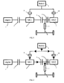
- FIG. 1 it is a schematic view illustrating the hybrid power output system according to the present invention.
- the system is used to output the power to the wheel driving shaft and the wheels so as to propel the vehicle.
- This hybrid power output system comprises an engine 1, a first motor 2, a second motor 3, a battery 6, a first clutch 4, a second clutch 5 and a third clutch 11, wherein the first motor 2 and the second motor 3 are connected electrically with the battery 6; the engine 1 is connected to the first motor 2 via the first clutch 4; the first motor 2 is connected to a wheel driving shaft 8 via the second clutch 5; the second motor 3 is connected to the wheel driving shaft 8 via the third clutch 11; and the second clutch 5 and the third clutch 11 are arranged between the first motor 2 and the second motor 3.
- the engine 1, the first clutch 4, the first motor 2, the second clutch 5, the third clutch 11 and the second motor 3 may be connected in sequence and coaxially, that is, the rotating shafts of the first motor 2 and the second motor 3 are arranged coaxially with the output shaft of the engine 1.
- the output shaft of the engine 1 is connected with the rotating shaft of the first motor 2 via the first clutch 4, the rotating shaft of the first motor 2 is connected with the rotating shaft of the second motor 3 via the second clutch 5 and the third clutch 11, and the wheel driving shaft 8 may be arranged between the second clutch 5 and the third clutch 11.
- the first motor 2 and the second motor 3 may be AC motors such as the permanent magnet synchronous motor. These two motors each can be functional as a generator for generating electricity or an electric motor for driving.
- the battery 6 is a controllable energy storage unit, which may be, but not limited to, a lithium battery, an iron battery, a nickel-hydrogen battery, a nickel-chrome battery and so on.
- the first motor 2 and the second motor 3 may be respectively connected electrically with the battery 6 through a first power converter 9 and a second power converter 10.
- the first power converter 9 and the second power converter 10 may have the bi-directional power conversion, thus, through the conversion of power switching unit, the motors may convert the electrical energy stored in the battery 6 into the power output, and may also convert the power into the electrical energy for storing in the battery 6.
- the first motor 2 is connected with the engine 1, the wheel driving shaft 8 and the battery, such that the energy can be converted or transferred among the output shaft of the engine 1, the battery 6 and the wheel driving shaft 8.
- the first motor 2 is coupled with the output shaft of the engine 1 via the engaged first clutch 4, and receives electrical energy from the battery 6 to produce adequate torque for starting the engine 1.
- the first motor 2 may also generate electrical energy to charge the battery 6 under the driving of the engine 1.
- the second motor 3 operates more efficiently than that of the first motor 2 at a low rotary speed, with the power higher than that of the first motor 2, and is mainly operated for driving the wheels alone in a purely electrical manner when the vehicle is started from the rest or is traveling at a low speed.
- the first motor 2 can be operated to drive the wheels together with the second motor 3 in the purely electrical manner.
- the first motor 2 operates more efficiently than that of the second motor 3 at a high rotary speed, such that it can be used to start the engine 1 alone, and also can be used to drive the wheels alone in the purely electrical manner.
- the higher efficiency range of the engine 1 is usually at the relatively high rotary speed.
- the motor is used for electrically propelling the vehicle, while the engine is not required for propelling. Therefore, the engine can be avoided to operate in a low efficiency range, which may cause high consumption of fuel and high emission of pollutants.
- the second clutch 5 shall be switched to be engaged.
- the first motor 2 and the second motor 3 can be operated to be at a substantially same speed, and then the second clutch 5 is operated to engage.
- the first motor 2 and the second motor 3 are able to provide adequate torque to meet the requirement for heavy load of the vehicle, and the engine is not required for such a heavy load, and therefore the engine is avoided to work in a low efficiency range.
- the engine 1 can work using the fuel such as gasoline and diesel, and output the power through the wheel driving shaft 8.
- the second motor 3 is preferably connected to the wheel driving shaft 8 via a fixed ratio reduction unit 7.
- the fixed ratio reduction unit 7 is located between the second clutch 5 and the third clutch 11, so as to meet the requirement for arrangement of the vehicle.
- the fixed ratio reduction unit may be but not limited to a constant-mesh gear-drive reduction unit, a constant-mesh chain-drive reduction unit or a constant-mesh friction-drive reduction unit, so long as the speed can be reduced and the reduction ratio is constant.
- the present invention may be operated in the modes of purely electrical energy operation, purely engine operation, series-hybrid operation, parallel-hybrid operation and series-parallel operation.
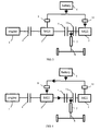
- Fig. 2 , Fig. 3 and Fig. 4 are the views illustrating that the driving shaft 8 is only driven based on the power output of the motor(s), which is the so-called purely electrical energy operation mode of the hybrid power system, that is, the engine 1 is stopped, only the motor is used for propelling the vehicle.
- the motor(s) which is the so-called purely electrical energy operation mode of the hybrid power system, that is, the engine 1 is stopped, only the motor is used for propelling the vehicle.
- Fig. 2 it shows the operation mode in which both the first motor 2 and the second motor 3 are operated for propelling the driving shaft 8, at this time the second clutch 5 and the third clutch 11 is engaged.
- the rotating shafts of both motors may simultaneously transfer the torque to the driving shaft 8; the first motor 2 and the second motor 3 work under the electrical energy operation mode, the battery 6 provides the electrical energy to both motors.
- the battery 6 provides the electrical energy to the first motor 2 and the second motor 3, and then the latter may output the torque to the driving shaft 8.
- Fig. 3 it shows the operation mode in which only the second motor 3 is operated to propelling the vehicle, at this time, the second clutch 5 is disengaged, the third clutch 11 is engaged, the first motor 2 is stopped, the second motor 3 is operated under the electrical energy operation mode, the battery 6 provides the electrical energy for the second motor 3. As indicated by the arrow in Fig. 3 , the battery 6 provides the electrical energy to the second motor 3, and the second motor 3 output the torque to the driving shaft 8.
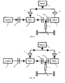
- Fig. 4 shows the operation mode in which only the first motor 2 is operated to propelling the vehicle, at this time, the second clutch 5 is engaged, the third clutch 11 is disengaged, the second motor 3 is stopped, the first motor 2 is operated under the electrical energy operation mode, the battery 6 provides the electrical energy for the first motor 2. As indicated by the arrow in Fig. 4 , the battery 6 provides the electrical energy to the first motor 2, and the first motor 2 output the torque to the driving shaft 8. Because the second motor 3 is disconnected from the wheel driving shaft 8, the second motor 3 will not be idle and, as a result, it will be avoided to waste energy.
- Fig. 5 and Fig. 6 show operation mode in which the engine 1 is operated, but the driving shaft 8 is only driven by the second motor 3, which is usually called as the series-hybrid operation mode.
- the second clutch 5 is disengaged, the third clutch 11 is engaged, thus the mechanical connection between the first motor 2 (and the engine 1) and the driving shaft 8 is disconnected; the first clutch 4 is engaged, connecting the output shaft of the engine 1 with the rotating shaft of the first motor 2; the power from the engine 1 is transferred to the first motor 2, the first motor 2 is operated in the generating mode, the second motor 3 is operated in the electrical energy operation mode.
- the battery 6 when the battery 6 is required to be charged, partial electrical energy from the first motor 2 is used to charge the battery 6, while the remain is transferred to the second motor 3, the second motor 3 provides the torque to the driving shaft 8.
- the electrical energy from the first motor 2 is transferred to the second motor 3, the battery 6 also gives the electrical energy to the second motor 3, and the second motor 3 transfers the torque to the driving shaft 8.
- Fig. 7, Fig. 8 and Fig. 9 show the operation mode in which the engine 1 is used to propel the driving shaft 8, and at the same time, the electrical energy from the battery 6 is also consumed to produce the drive force to the driving shaft 8, which is usually called as the parallel-hybrid operation mode.
- both the first clutch 4 and the second clutch 5 are engaged, the third clutch 11 is engaged or disengaged, thus enable the output shaft of the engine 1 mechanically connected with the rotating shaft of the first motor 2, enable the first motor 2 (or the second motor 3) mechanically connected with the driving shaft 8.
- the power can be flowed in different manners.
- Fig. 7 shows the first power flow manner, wherein the first clutch 4, the second clutch 5 and the third clutch 11 are all engaged, and the first motor 2 and the second motor 3 both are working under the battery energy; the battery 6 provides the required electrical energy for the two motors.
- the engine 1 functions and transfers the torque to the driving shaft 8 through the rotating shaft of the first motor 2.
- the first motor 2 and the second motor 3 may convert the electrical energy from the battery 6, and output the torque to the driving shaft 8.
- Fig. 8 shows the second power flow manner, wherein the first clutch 4, the second clutch 5 and the third clutch 11 are all engaged.
- the first motor 2 is idle, the second motor 3 operates under the battery energy; the battery 6 may provide the electrical energy as required.
- the engine 1 functions to transmit the torque to the driving shaft 8 through the rotating shaft of the first motor 2.
- the second motor 3 may receive the electrical energy from the battery 6 to provide torque to the driving shaft 8.
- Fig. 9 shows the third power flow manner, wherein the third clutch 11 is disengaged, while the first clutch 4 and the second clutch 5 are engaged.
- the second motor 3 is disconnected from the wheel driving shaft 8, and the first motor 2 operates under the battery energy; the battery 6 may provide the electrical energy as required.
- the engine 1 functions to transmit the torque to the driving shaft 8 through the rotating shaft of the first motor 2.
- the first motor 2 may receive the electrical energy from the battery 6 to provide torque to the driving shaft 8.
- Fig. 10 and Fig. 11 show the operation mode in which the engine 1 output the power, the first motor 2 is generating the electricity, and the second motor 3 operates under the electrically driving mode, which is usually called as the series-parallel operation mode.
- partial power of the engine 1 is directly transferred to the driving shaft, the remain is used for driving the first motor 2 to work under the electricity-generating mode, and the second motor 3 is operating in the electrical energy mode.
- partial electrical energy generated by the first motor 2 is directly transferred to the second motor 3, enable the second motor 3 electrically drive the wheels, and the remain is charging the battery 6.
- the electrical energy generated by the first motor 2 is directly sent to the second motor 3, and the battery 6 also provides the electrical energy to the second motor 3, such that the second motor 3 electrically drive the wheels.
- Fig. 12 and Fig. 13 show the operation mode in which the driving shaft 8 is only propelled by the engine 1, which is usually called as the purely engine operation mode, and at this time, both the first clutch 4 and the second clutch 5 are engaged, and the third clutch 11 is disengaged. Because the second motor 3 is disconnected from the wheel driving shaft 8, the second motor 3 will not be idle and, as a result, it will be avoided to waste energy.
- Fig. 12 shows the operation mode in which the first motor 2 is idle and the second motor 3 is stopped, and the rotating shaft of the first motor 2 is used to transfer the torque from the engine 1 to the driving shaft 8.
- the engine 1 functions and transfers the torque to the driving shaft 8 through the rotating shaft of the first motor 2.
- Fig. 13 shows the operation mode in which the first motor 2 transfers partial power from engine 1 into electrical energy for charging the battery 6, and at the same time its rotating shaft transfers the remaining power from the engine 1 to the driving shaft 8.
- the engine 1 starts, and a part of the power thereof is transferred to the driving shaft 8 through the rotating shaft of the first motor 2, and the other part of the power is converted into electrical energy by the first motor 2 and stored in the battery 6.
- Fig. 14 and Fig. 15 are views illustrating the energy recover operation mode of the present invention.
- the present invention can be used to recover energy.
- the motor works in electricity generating mode, and transfers the power feedback from the driving shaft 8 into the electrical energy for charging the battery 6.
- the energy may be recovered in different manners.
- Fig. 14 shows the energy recover mode in which both the second clutch 5 and the third clutch 11 are engaged.
- the rotating shafts of both the first motor 2 and the second motor 3 are connected with the driving shaft 8, and the first motor 2 and the second motor 3 are working under the electricity generating mode, for storing the recovered electricity to the battery 6.
- the driving shaft 8 feedbacks the mechanical energy from the wheels to the first motor 2 and the second motor 3, and the latter is operated to convert the mechanical energy into electrical energy for charging the battery 6 to realize the energy recover purpose.
- Fig. 15 shows the energy recover mode in which the second clutch 5 is disengaged and the third clutch 11 is engaged.
- the rotating shaft of the second motor 3 is connected with the driving shaft 8, the second motor 3 is working under the electricity generating mode, for storing the recovered electrical energy to the battery 6.
- the driving shaft feedbacks the mechanical energy from the wheels to the second motor 3, and the second motor 3 converts the mechanical energy into the electrical energy for charging the battery 6 to realize the energy recover purpose.
- Fig. 16 is a view illustrating the operation mode in which the battery is charging while the vehicle is parking.
- the second clutch 5 is disengaged and the second motor 3 is stopped, the engine 1 drives the first motor 2 to work under the electricity generation mode, and stores the electrical energy into the battery 6.
- the engine 1 starts to drive the first motor 2, and the first motor 2 is driven to convert the power from the engine 1 into the electrical energy for charging the battery 6.
Claims (7)
- Hybridleistungsausgabesystem zum Ausgeben von Leistung zu einer Radantriebswelle zum Vorwärtstreiben eines Fahrzeugs, wobei das System einen Maschine (1), einen ersten Motor (2), einen zweiten Motor (3), eine Batterie (6), eine zweite Kupplung (5) und eine dritte Kupplung (11) aufweist, wobei:der erste Motor (2) und der zweite Motor (3) elektrisch mit der Batterie (6) verbunden sind;der erste Motor (2) mit einer Radantriebswelle mittels der zweiten Kupplung (5) verbunden ist;der zweite Motor mit der Radantriebswelle mittels der dritten Kupplung verbunden ist;die zweite Kupplung und die dritte Kupplung zwischen dem ersten Motor und dem zweiten Motor angeordnet sind;dadurch gekennzeichnet, dass es ferner aufweist:eine erste Kupplung (4),wobei die Maschine mit dem ersten Motor mittels der ersten Kupplung verbunden ist,der erste Motor (2) derart gestaltet ist, dass er effizienter als der zweite Motor (3) bei einer hohen Rotationsgeschwindigkeit betrieben wird, während der zweite Motor (3) so gestaltet ist, dass er effizienter als der erste Motor (2) bei einer niedrigen Rotationsgeschwindigkeit betrieben wird,wobei das Hybridleistungsausgabesystem in einem rein elektrischen Betrieb betreibbar ist, wobei, wenn ein Fahrzeug aus dem Ruhezustand gestartet wird oder sich bei einer niedrigen Geschwindigkeit fortbewegt, der zweite Motor (3) so betrieben wird, dass er allein die Räder antreibt, wenn die Geschwindigkeit bis zu einem bestimmten Wert ist, bei dem der erste Motor (2) mit einer höheren Effizienz arbeiten kann, der erste Motor (2) so betrieben wird, dass er allein die Räder antreibt, und wenn die Geschwindigkeit moderat ist, der erste und der zweite Motor zum Antreiben der Räder zusammenarbeiten.
- Hybridleistungsausgabesystem nach Anspruch 1, bei dem die Maschine, die erste Kupplung, der erste Motor, die zweite Kupplung, die dritte Kupplung und der zweite Motor in Reihe und koaxial verbunden sind.
- Hybridleistungsausgabesystem nach Anspruch 1 oder 2, bei dem der erste Motor als Mittelgeschwindigkeits- oder Hochgeschwindigkeitsmotor ausgestaltet ist, der zweite Motor als Mittelgeschwindigkeits- oder Hochgeschwindigkeitsmotor ausgestaltet ist.
- Hybridleistungsausgabesystem nach Anspruch 1 oder 2, bei dem die Leistung des zweiten Motors größer als die des ersten Motors ist.
- Hybridleistungsausgabesystem nach Anspruch 1, bei dem der erste Motor und der zweite Motor jeweils elektrisch mit der Batterie mittels eines Leistungswandlers verbunden sind.
- Hybridleistungsausgabesystem nach Anspruch 1, bei dem der zweite Motor mit der Radantriebswelle mittels der dritten Kupplung und einer Reduktionseinheit bei konstantem Zahneingriff (7) und festem Verhältnis in Reihe verbunden ist.
- Hybridleistungsausgabesystem nach Anspruch 6, bei dem die Reduktionseinheit bei festem Verhältnis eine Getriebeantriebsreduktionseinheit bei konstantem Zahneingriff, eine Kettenantriebsreduktionseinheit bei konstantem Zahneingriff oder eine Reibungsantriebsreduktionseinheit bei konstantem Zahneingriff ist.
Applications Claiming Priority (2)
| Application Number | Priority Date | Filing Date | Title |
|---|---|---|---|
| CNA2006101577276A CN101209667A (zh) | 2006-12-25 | 2006-12-25 | 混合动力输出装置 |
| PCT/CN2007/071298 WO2008077346A1 (en) | 2006-12-25 | 2007-12-21 | Hybrid power output system |
Publications (3)
| Publication Number | Publication Date |
|---|---|
| EP2094516A1 EP2094516A1 (de) | 2009-09-02 |
| EP2094516A4 EP2094516A4 (de) | 2010-09-08 |
| EP2094516B1 true EP2094516B1 (de) | 2013-05-01 |
Family
ID=39562106
Family Applications (1)
| Application Number | Title | Priority Date | Filing Date |
|---|---|---|---|
| EP07846124.1A Active EP2094516B1 (de) | 2006-12-25 | 2007-12-21 | Hybridantriebsstrang |
Country Status (4)
| Country | Link |
|---|---|
| US (1) | US8307924B2 (de) |
| EP (1) | EP2094516B1 (de) |
| CN (1) | CN101209667A (de) |
| WO (1) | WO2008077346A1 (de) |
Cited By (1)
| Publication number | Priority date | Publication date | Assignee | Title |
|---|---|---|---|---|
| CN105082966A (zh) * | 2015-09-09 | 2015-11-25 | 华英汽车集团有限公司 | 一种双电机动力系统、换挡方法及电动汽车 |
Families Citing this family (58)
| Publication number | Priority date | Publication date | Assignee | Title |
|---|---|---|---|---|
| TWI330218B (en) * | 2004-10-29 | 2010-09-11 | Tai Her Yang | Split serial-parallel hybrid dual-power drive system |
| EP2086781B1 (de) * | 2006-12-08 | 2013-05-01 | Byd Company Limited | Hybridantriebsstrang |
| US8337359B2 (en) | 2008-08-27 | 2012-12-25 | EcoMotors International | Hybrid engine system |
| US8290653B2 (en) * | 2008-08-27 | 2012-10-16 | Ecomotors International, Inc. | Powertrain with multiple, selectable power sources |
| CN101659204B (zh) * | 2008-08-29 | 2015-07-22 | 比亚迪股份有限公司 | 一种混合动力驱动系统及其驱动方法 |
| CN102216131B (zh) * | 2008-10-15 | 2013-10-16 | 格特拉克·福特传动系统有限公司 | 设有驱动系的车辆 |
| CN101585314B (zh) * | 2009-06-08 | 2012-12-05 | 浙江吉利汽车研究院有限公司 | 混合动力驱动系统 |
| CN101920653B (zh) * | 2009-06-17 | 2015-02-18 | 上海捷能汽车技术有限公司 | 一种混合动力驱动系统的动力传输单元及传输控制方法 |
| US8955625B2 (en) * | 2009-09-11 | 2015-02-17 | ALTe Technologies, Inc. | Stackable motor |
| CN102085795B (zh) * | 2009-12-04 | 2015-04-15 | 上海汽车集团股份有限公司 | 一种车用离合器动力藕合同步器换档混合动力驱动系统 |
| CN101875297B (zh) * | 2009-12-10 | 2013-07-10 | 安徽巨一自动化装备有限公司 | 一种双电机混合动力驱动及变速装置 |
| DE102010012667B4 (de) * | 2010-03-24 | 2012-06-21 | Voith Patent Gmbh | Antriebsvorrichtung |
| CN102310756B (zh) * | 2010-06-29 | 2013-11-20 | 北汽福田汽车股份有限公司 | 混合动力汽车用动力总成和混合动力汽车 |
| CN102310755B (zh) * | 2010-06-29 | 2014-05-28 | 北汽福田汽车股份有限公司 | 动力耦合装置及其控制装置、混合动力系统 |
| EP2636567B1 (de) * | 2010-11-04 | 2016-01-06 | Toyota Jidosha Kabushiki Kaisha | Steuerungsvorrichtung für ein hybridfahrzeug |
| US8678116B2 (en) * | 2010-12-31 | 2014-03-25 | Cummins Inc. | Accessory drive configuration |
| DE102011106399A1 (de) * | 2011-07-02 | 2013-01-03 | Magna E-Car Systems Gmbh & Co Og | Antriebsstrang |
| DE112011105983T5 (de) * | 2011-12-19 | 2014-11-27 | Toyota Jidosha Kabushiki Kaisha | Antriebssteuerungsvorrichtung für ein Hybridfahrzeug |
| US9580062B2 (en) * | 2012-01-10 | 2017-02-28 | Ford Global Technologies, Llc | Method for increasing fuel economy of plug-in hybrid electric vehicles |
| CN102555769B (zh) * | 2012-03-12 | 2014-12-10 | 重庆大学 | 一种混联式双电机多工作模式混合动力驱动总成 |
| CN104203694B (zh) | 2012-03-26 | 2015-12-02 | 丰田自动车株式会社 | 车辆的控制装置 |
| DE102013013623B4 (de) | 2012-08-29 | 2022-06-30 | Kanzaki Kokyukoki Mfg. Co., Ltd. | Motorsteuersystem für ein mit elektrischem Motor angetriebenes Fahrzeug |
| CN204136757U (zh) * | 2013-02-08 | 2015-02-04 | 高效动力传动系统公司 | 用于双电机双离合混合动力车的动力系统配置及双电机双离合混合动力车 |
| US10384527B2 (en) * | 2013-02-08 | 2019-08-20 | Cummins Electrified Power Na Inc. | Four wheel drive powertrain configurations for two-motor, two-clutch hybrid electric vehicles |
| US9045136B2 (en) | 2013-02-08 | 2015-06-02 | Efficient Drivetrains, Inc. | Systems and methods for implementing dynamic operating modes and control policies for hybrid electric vehicles |
| US9421856B2 (en) | 2013-02-08 | 2016-08-23 | Efficient Drivetrains Inc. | Powertrain configurations for two-motor, two-clutch hybrid electric vehicles |
| US10836375B2 (en) | 2013-02-08 | 2020-11-17 | Cummins Electrified Power Na Inc. | Powertrain configurations for single-motor, two-clutch hybrid electric vehicles |
| CN103241117A (zh) * | 2013-05-16 | 2013-08-14 | 哈尔滨耦合动力工程技术中心有限公司 | 磁力耦合的串联结构汽车混合动力系统及工作方法 |
| CN103287562B (zh) * | 2013-06-07 | 2016-02-24 | 哈尔滨耦合动力工程技术中心有限公司 | 柴油机发电机电动机集成的船舶混合动力系统及混合方法 |
| CN104249733A (zh) * | 2013-06-28 | 2014-12-31 | 上海汽车集团股份有限公司 | 一种车辆能量回收控制方法 |
| CN103407364B (zh) * | 2013-07-27 | 2016-08-10 | 哈尔滨耦合动力工程技术中心有限公司 | 发动机发电机齿轮箱驱动的汽车混合动力系统及混合方法 |
| WO2015017810A1 (en) * | 2013-08-01 | 2015-02-05 | Chevron U.S.A. Inc. | Electric submersible pump having a plurality of motors operatively coupled thereto and methods of using |
| CN103358878B (zh) * | 2013-08-08 | 2016-06-08 | 哈尔滨耦合动力工程技术中心有限公司 | 能量回收式的磁力耦合汽车混合动力充电系统及充电方法 |
| CN103386880B (zh) * | 2013-08-14 | 2017-03-01 | 哈尔滨耦合动力工程技术中心有限公司 | 绿色环保的磁力耦合汽车混合动力系统及混合方法 |
| US9193273B1 (en) | 2014-06-15 | 2015-11-24 | Efficient Drivetrains, Inc. | Vehicle with AC-to-DC inverter system for vehicle-to-grid power integration |
| GB2531767A (en) * | 2014-10-29 | 2016-05-04 | Bamford Excavators Ltd | Working Machine |
| GB2532731A (en) * | 2014-11-25 | 2016-06-01 | Eric Hawksley Graeme | Hybrid power system |
| CN105774795B (zh) * | 2014-12-19 | 2018-11-09 | 北京宝沃汽车有限公司 | 并联式混合动力系统车辆的扭矩分配方法及系统 |
| DE102015000466B4 (de) * | 2015-01-15 | 2016-11-17 | Audi Ag | Antriebsvorrichtung für ein Kraftfahrzeug und Kraftfahrzeug |
| EP3386788A1 (de) * | 2015-12-07 | 2018-10-17 | Dana Heavy Vehicle Systems Group, LLC | Verteilte antriebsarchitekturen für nutzfahrzeuge mit hybrid-elektroantrieb |
| EP3386789A1 (de) | 2015-12-07 | 2018-10-17 | Dana Heavy Vehicle Systems Group, LLC | Architekturen für verteilten antriebsstrang für nutzfahrzeuge mit hybridem elektrischem antriebsstrang und achsen mit zweibereichsentkopplung |
| CN105774537A (zh) * | 2016-03-24 | 2016-07-20 | 重庆大学 | 采用双离合两挡自动变速器的增程式电动汽车动力系统 |
| EP3436299B1 (de) | 2016-03-28 | 2020-02-12 | Dana Heavy Vehicle Systems Group, LLC | Elektrische antriebsstrangachsen mit mehrganggetrieben |
| WO2017172614A1 (en) | 2016-03-28 | 2017-10-05 | Dana Heavy Vehicle Systems Group, Llc | Single electric motor drive axle with multiple rations |
| CN108001205B (zh) * | 2016-10-31 | 2020-07-10 | 比亚迪股份有限公司 | 动力传动系统以及具有其的车辆 |
| US10857881B2 (en) | 2016-11-15 | 2020-12-08 | Dana Heavy Vehicle Systems Group, Llc | Electric drivetrain for a tandem drive axle |
| JP6353576B1 (ja) * | 2017-03-22 | 2018-07-04 | 株式会社ユニバンス | 動力伝達装置 |
| KR102335351B1 (ko) * | 2017-07-10 | 2021-12-03 | 현대자동차 주식회사 | 두 개의 모터를 갖는 동력 시스템 |
| CN109515146A (zh) * | 2017-09-18 | 2019-03-26 | 郑州宇通客车股份有限公司 | 一种纯电动客车及其动力系统 |
| DE102017130494A1 (de) | 2017-12-19 | 2019-06-19 | Schaeffler Technologies AG & Co. KG | Hybrid-Antriebsstrang |
| CN108482099A (zh) * | 2018-04-03 | 2018-09-04 | 朱珍 | 一种车用智能车用复合循环式动力系统 |
| CN110341454A (zh) * | 2019-07-11 | 2019-10-18 | 山西成功汽车制造有限公司 | 一种双发动机混合动力重型车驱动系统及其使用方法 |
| CN110450616A (zh) * | 2019-08-14 | 2019-11-15 | 四川阿尔特新能源汽车有限公司 | 驱动系统、驱动控制方法、装置及混合动力车辆 |
| CN110450618A (zh) * | 2019-08-14 | 2019-11-15 | 四川阿尔特新能源汽车有限公司 | 混合动力驱动系统、驱动控制方法、装置及混合动力车辆 |
| US11407307B2 (en) | 2020-03-23 | 2022-08-09 | Arvinmeritor Technology, Llc | Drive axle system having multiple electric motors |
| DE102020209516A1 (de) * | 2020-07-29 | 2022-02-03 | Zf Friedrichshafen Ag | Antriebsstrang für ein Hybridfahrzeug |
| CN112659879B (zh) * | 2020-12-28 | 2022-05-13 | 中国第一汽车股份有限公司 | 一种纵置车辆动力总成及车辆动力控制方法 |
| WO2022204737A1 (en) * | 2021-04-01 | 2022-10-06 | Jacobs Engineering Group Cc | Super range extension control system for electric vehicles (evs) |
Citations (1)
| Publication number | Priority date | Publication date | Assignee | Title |
|---|---|---|---|---|
| US5845731A (en) * | 1996-07-02 | 1998-12-08 | Chrysler Corporation | Hybrid motor vehicle |
Family Cites Families (52)
| Publication number | Priority date | Publication date | Assignee | Title |
|---|---|---|---|---|
| JPH11280512A (ja) * | 1998-03-30 | 1999-10-12 | Nissan Motor Co Ltd | ハイブリッド車両 |
| JP3536658B2 (ja) * | 1998-03-31 | 2004-06-14 | 日産自動車株式会社 | ハイブリッド車両の駆動制御装置 |
| US6276472B1 (en) * | 1998-04-01 | 2001-08-21 | Denso Corporation | Control system for hybrid vehicle |
| US5931757A (en) * | 1998-06-24 | 1999-08-03 | General Motors Corporation | Two-mode, compound-split electro-mechanical vehicular transmission |
| JP3449226B2 (ja) * | 1998-07-03 | 2003-09-22 | 日産自動車株式会社 | ハイブリッド車両のバッテリー制御装置 |
| JP3409701B2 (ja) * | 1998-07-03 | 2003-05-26 | 日産自動車株式会社 | ハイブリッド車両の制御装置 |
| US6554088B2 (en) * | 1998-09-14 | 2003-04-29 | Paice Corporation | Hybrid vehicles |
| JP3514142B2 (ja) * | 1998-11-04 | 2004-03-31 | 日産自動車株式会社 | 車両制御装置 |
| US6203468B1 (en) * | 1998-11-18 | 2001-03-20 | Fuji Jukogyo Kabushiki Kaisha | Control device for hybrid vehicle and method thereof |
| DE19917665A1 (de) | 1999-04-19 | 2000-10-26 | Zahnradfabrik Friedrichshafen | Hybridantrieb für ein Kraftfahrzeug |
| DE10036504B4 (de) * | 1999-08-02 | 2011-05-19 | Schaeffler Technologies Gmbh & Co. Kg | Antriebsstrang |
| FR2809352B1 (fr) * | 2000-05-25 | 2002-08-16 | Renault | Groupe motopropulseur d'un vehicule hybride et son procede de commande |
| JP3569210B2 (ja) * | 2000-08-11 | 2004-09-22 | 本田技研工業株式会社 | ハイブリッド車両の動力伝達装置及びその制御方法 |
| US6450275B1 (en) * | 2000-11-02 | 2002-09-17 | Ford Motor Company | Power electronics cooling for a hybrid electric vehicle |
| JP2002199506A (ja) * | 2000-12-22 | 2002-07-12 | Mazda Motor Corp | ハイブリッド駆動装置 |
| US6478705B1 (en) | 2001-07-19 | 2002-11-12 | General Motors Corporation | Hybrid electric powertrain including a two-mode electrically variable transmission |
| JP3707411B2 (ja) * | 2001-09-28 | 2005-10-19 | トヨタ自動車株式会社 | 動力出力装置およびこれを備える自動車 |
| CN1301200C (zh) * | 2002-09-13 | 2007-02-21 | 本田技研工业株式会社 | 混合车辆 |
| US6962545B2 (en) * | 2002-09-23 | 2005-11-08 | Bae Systems Onctrols | Multi-range parallel-hybrid continuously variable transmission |
| US6600980B1 (en) * | 2002-09-26 | 2003-07-29 | Ford Global Technologies, Llc | Torque reversal reduction strategy for a hybrid vehicle |
| CN1291855C (zh) * | 2002-12-08 | 2006-12-27 | 中国第一汽车集团公司 | 双电机混合动力汽车动力系统 |
| EP1524145A3 (de) * | 2003-10-15 | 2006-01-04 | Nissan Motor Company, Limited | Antriebsstrang für Hybridfahrzeug |
| JP4069901B2 (ja) * | 2004-05-20 | 2008-04-02 | トヨタ自動車株式会社 | ハイブリッド車のドライブトレーン |
| CN100354154C (zh) | 2004-08-16 | 2007-12-12 | 上海比亚迪有限公司 | 混合动力汽车动力系统 |
| AT8336U1 (de) * | 2004-09-27 | 2006-06-15 | Magna Steyr Fahrzeugtechnik Ag | Antriebseinheit für kraftfahrzeug mit hybridantrieb in längsanordnung |
| JP4341611B2 (ja) * | 2005-11-09 | 2009-10-07 | 日産自動車株式会社 | ハイブリッド車両のエンジン再始動制御装置 |
| JP4301212B2 (ja) * | 2005-06-03 | 2009-07-22 | 日産自動車株式会社 | 車両の制御装置 |
| US7625307B2 (en) * | 2005-10-21 | 2009-12-01 | Gm Global Technology Operations, Inc. | Mechatronic hybrid transmissions having two planetary gear sets and three motor/generators |
| US7371201B2 (en) * | 2005-10-21 | 2008-05-13 | Gm Global Technology Operations, Inc. | Hybrid transmissions having three motor/generators and three interconnected planetary gear members |
| US7371202B2 (en) * | 2005-10-21 | 2008-05-13 | Gm Global Technology Operations, Inc. | Mechatronic hybrid transmissions having three planetary gear sets and three motor/generators |
| US7344464B2 (en) * | 2005-10-21 | 2008-03-18 | Gm Global Technology Operations, Inc. | Hybrid architecture incorporating three motor generators and a stationary planetary gear member |
| US7422534B2 (en) * | 2005-10-21 | 2008-09-09 | Gm Global Technology Operations, Inc. | Hybrid transmissions having three motor/generators and three interconnected planetary gear sets |
| US7468014B2 (en) * | 2005-10-21 | 2008-12-23 | Gm Global Technology Operations, Inc. | Hybrid architecture incorporating three motor generators and planetary gear arrangment having a stationary member |
| US7507173B2 (en) * | 2005-10-21 | 2009-03-24 | Gm Global Technology Operations, Inc. | Hybrid architecture incorporating three motor generators and planetary gear sets with two fixed interconnections |
| US7341535B2 (en) * | 2005-10-21 | 2008-03-11 | Gm Global Technology Operations, Inc. | Hybrid transmissions having three motor/generators and a stationary planetary gear member |
| JP4077003B2 (ja) * | 2005-10-26 | 2008-04-16 | トヨタ自動車株式会社 | 電動車両駆動制御装置及びその制御方法 |
| JP4215070B2 (ja) * | 2006-04-26 | 2009-01-28 | トヨタ自動車株式会社 | 車両用駆動装置の制御装置 |
| US7908063B2 (en) * | 2006-05-03 | 2011-03-15 | GM Global Technology Operations LLC | Synchronous shift execution for hybrid transmission |
| US7591747B2 (en) * | 2006-05-25 | 2009-09-22 | Gm Global Technology Operations, Inc. | Electrically variable transmission having three planetary gear sets, two fixed interconnections and clutched input |
| US7374506B2 (en) * | 2006-05-25 | 2008-05-20 | Gm Global Technology Operations, Inc. | Electrically variable transmission having three planetary gear sets, a stationary member, three fixed interconnections and clutched input |
| JP4492585B2 (ja) * | 2006-05-29 | 2010-06-30 | 日産自動車株式会社 | ハイブリッド車両の制御装置及びハイブリッド車両の制御方法。 |
| US7507174B2 (en) * | 2006-07-14 | 2009-03-24 | Gm Global Technology Operations, Inc. | Electrically variable transmission having three planetary gear sets |
| US7494436B2 (en) * | 2006-07-24 | 2009-02-24 | Gm Global Technology Operations, Inc. | Hybrid architecture incorporating three interconnected gear sets and brakes |
| US7479080B2 (en) * | 2006-07-24 | 2009-01-20 | Gm Global Technology Operations, Inc. | Hybrid architecture incorporating three motor generators and brakes |
| US7748482B2 (en) * | 2006-10-25 | 2010-07-06 | Gm Global Technology Operations, Inc. | Accessory drive system for a hybrid vehicle |
| US7479082B2 (en) * | 2006-11-17 | 2009-01-20 | Gm Global Technology Operations, Inc. | Hybrid powertrain having three interconnecting members and brakes |
| US7481731B2 (en) * | 2006-11-17 | 2009-01-27 | Gm Global Technology Operations, Inc. | Hybrid powertrain having three planetary gearsets and brakes |
| US7597648B2 (en) * | 2006-11-28 | 2009-10-06 | Gm Global Technology Operations, Inc. | Input brake providing electric only fixed gear |
| EP2086781B1 (de) * | 2006-12-08 | 2013-05-01 | Byd Company Limited | Hybridantriebsstrang |
| CN101209666A (zh) * | 2006-12-25 | 2008-07-02 | 比亚迪股份有限公司 | 混合动力输出装置 |
| US7704176B2 (en) * | 2007-01-31 | 2010-04-27 | Gm Global Technology Operations, Inc. | Electrically variable transmission device using multiple pairings of electrical machines |
| US7980980B2 (en) * | 2007-11-14 | 2011-07-19 | GM Global Technology Operations LLC | Hybrid powertrain |
-
2006
- 2006-12-25 CN CNA2006101577276A patent/CN101209667A/zh active Pending
-
2007
- 2007-12-21 WO PCT/CN2007/071298 patent/WO2008077346A1/en active Application Filing
- 2007-12-21 EP EP07846124.1A patent/EP2094516B1/de active Active
- 2007-12-21 US US12/521,055 patent/US8307924B2/en active Active
Patent Citations (1)
| Publication number | Priority date | Publication date | Assignee | Title |
|---|---|---|---|---|
| US5845731A (en) * | 1996-07-02 | 1998-12-08 | Chrysler Corporation | Hybrid motor vehicle |
Cited By (1)
| Publication number | Priority date | Publication date | Assignee | Title |
|---|---|---|---|---|
| CN105082966A (zh) * | 2015-09-09 | 2015-11-25 | 华英汽车集团有限公司 | 一种双电机动力系统、换挡方法及电动汽车 |
Also Published As
| Publication number | Publication date |
|---|---|
| EP2094516A4 (de) | 2010-09-08 |
| US20110120788A1 (en) | 2011-05-26 |
| US8307924B2 (en) | 2012-11-13 |
| EP2094516A1 (de) | 2009-09-02 |
| CN101209667A (zh) | 2008-07-02 |
| WO2008077346A1 (en) | 2008-07-03 |
Similar Documents
| Publication | Publication Date | Title |
|---|---|---|
| EP2094516B1 (de) | Hybridantriebsstrang | |
| EP2117868B1 (de) | Hybridantriebsstrang | |
| EP2086781B1 (de) | Hybridantriebsstrang | |
| US8262524B2 (en) | Hybrid powertrain | |
| US8818588B2 (en) | Parallel hybrid drive system utilizing power take off connection as transfer for a secondary energy source | |
| CN101450609B (zh) | 混合动力驱动系统及其驱动方法 | |
| CN101342859B (zh) | 混合动力驱动系统 | |
| US10017040B2 (en) | Drive unit for a hybrid vehicle | |
| CN102310756B (zh) | 混合动力汽车用动力总成和混合动力汽车 | |
| CN102085795A (zh) | 一种车用离合器动力藕合同步器换档混合动力驱动系统 | |
| US20190291566A1 (en) | Power transmission structure of hybrid vehicle with one motor generator and three clutches | |
| CN111114284B (zh) | 功率分流混合动力耦合系统及车辆 | |
| CN103009994A (zh) | 一种混合动力汽车动力耦合装置及变速系统 | |
| CN101585314B (zh) | 混合动力驱动系统 | |
| CN103072459A (zh) | 变速器、混合动力系统和混合动力汽车 | |
| CN102745060A (zh) | 混合动力驱动系统 | |
| CN114953961A (zh) | 混合动力耦合机构及车辆 | |
| CN217778348U (zh) | 混合动力变速器驱动系统 | |
| KR102578581B1 (ko) | 다기능 스타터-제네레이터를 이용한 플러그인 하이브리드자동차의 파워트레인 및 그 제어방법 | |
| CN209813714U (zh) | 一种单电机插电式混联混合动力系统 | |
| KR100837918B1 (ko) | 하이브리드용 무단 변속기 | |
| CN113085535A (zh) | 一种dmt双电机混动变速器 |
Legal Events
| Date | Code | Title | Description |
|---|---|---|---|
| PUAI | Public reference made under article 153(3) epc to a published international application that has entered the european phase |
Free format text: ORIGINAL CODE: 0009012 |
|
| 17P | Request for examination filed |
Effective date: 20090609 |
|
| AK | Designated contracting states |
Kind code of ref document: A1 Designated state(s): AT BE BG CH CY CZ DE DK EE ES FI FR GB GR HU IE IS IT LI LT LU LV MC MT NL PL PT RO SE SI SK TR |
|
| DAX | Request for extension of the european patent (deleted) | ||
| A4 | Supplementary search report drawn up and despatched |
Effective date: 20100809 |
|
| 17Q | First examination report despatched |
Effective date: 20100820 |
|
| REG | Reference to a national code |
Ref country code: DE Ref legal event code: R079 Ref document number: 602007030237 Country of ref document: DE Free format text: PREVIOUS MAIN CLASS: B60K0006387000 Ipc: B60K0006442000 |
|
| GRAP | Despatch of communication of intention to grant a patent |
Free format text: ORIGINAL CODE: EPIDOSNIGR1 |
|
| RIC1 | Information provided on ipc code assigned before grant |
Ipc: B60K 6/387 20071001ALI20121023BHEP Ipc: B60K 6/40 20071001ALI20121023BHEP Ipc: B60K 6/442 20071001AFI20121023BHEP |
|
| GRAS | Grant fee paid |
Free format text: ORIGINAL CODE: EPIDOSNIGR3 |
|
| GRAA | (expected) grant |
Free format text: ORIGINAL CODE: 0009210 |
|
| AK | Designated contracting states |
Kind code of ref document: B1 Designated state(s): AT BE BG CH CY CZ DE DK EE ES FI FR GB GR HU IE IS IT LI LT LU LV MC MT NL PL PT RO SE SI SK TR |
|
| REG | Reference to a national code |
Ref country code: GB Ref legal event code: FG4D |
|
| REG | Reference to a national code |
Ref country code: CH Ref legal event code: EP Ref country code: AT Ref legal event code: REF Ref document number: 609683 Country of ref document: AT Kind code of ref document: T Effective date: 20130515 |
|
| REG | Reference to a national code |
Ref country code: IE Ref legal event code: FG4D |
|
| REG | Reference to a national code |
Ref country code: DE Ref legal event code: R096 Ref document number: 602007030237 Country of ref document: DE Effective date: 20130627 |
|
| REG | Reference to a national code |
Ref country code: AT Ref legal event code: MK05 Ref document number: 609683 Country of ref document: AT Kind code of ref document: T Effective date: 20130501 |
|
| REG | Reference to a national code |
Ref country code: NL Ref legal event code: VDEP Effective date: 20130501 |
|
| REG | Reference to a national code |
Ref country code: LT Ref legal event code: MG4D |
|
| PG25 | Lapsed in a contracting state [announced via postgrant information from national office to epo] |
Ref country code: SI Free format text: LAPSE BECAUSE OF FAILURE TO SUBMIT A TRANSLATION OF THE DESCRIPTION OR TO PAY THE FEE WITHIN THE PRESCRIBED TIME-LIMIT Effective date: 20130501 Ref country code: PT Free format text: LAPSE BECAUSE OF FAILURE TO SUBMIT A TRANSLATION OF THE DESCRIPTION OR TO PAY THE FEE WITHIN THE PRESCRIBED TIME-LIMIT Effective date: 20130902 Ref country code: LT Free format text: LAPSE BECAUSE OF FAILURE TO SUBMIT A TRANSLATION OF THE DESCRIPTION OR TO PAY THE FEE WITHIN THE PRESCRIBED TIME-LIMIT Effective date: 20130501 Ref country code: FI Free format text: LAPSE BECAUSE OF FAILURE TO SUBMIT A TRANSLATION OF THE DESCRIPTION OR TO PAY THE FEE WITHIN THE PRESCRIBED TIME-LIMIT Effective date: 20130501 Ref country code: AT Free format text: LAPSE BECAUSE OF FAILURE TO SUBMIT A TRANSLATION OF THE DESCRIPTION OR TO PAY THE FEE WITHIN THE PRESCRIBED TIME-LIMIT Effective date: 20130501 Ref country code: IS Free format text: LAPSE BECAUSE OF FAILURE TO SUBMIT A TRANSLATION OF THE DESCRIPTION OR TO PAY THE FEE WITHIN THE PRESCRIBED TIME-LIMIT Effective date: 20130901 Ref country code: GR Free format text: LAPSE BECAUSE OF FAILURE TO SUBMIT A TRANSLATION OF THE DESCRIPTION OR TO PAY THE FEE WITHIN THE PRESCRIBED TIME-LIMIT Effective date: 20130802 Ref country code: SE Free format text: LAPSE BECAUSE OF FAILURE TO SUBMIT A TRANSLATION OF THE DESCRIPTION OR TO PAY THE FEE WITHIN THE PRESCRIBED TIME-LIMIT Effective date: 20130501 Ref country code: ES Free format text: LAPSE BECAUSE OF FAILURE TO SUBMIT A TRANSLATION OF THE DESCRIPTION OR TO PAY THE FEE WITHIN THE PRESCRIBED TIME-LIMIT Effective date: 20130812 |
|
| PG25 | Lapsed in a contracting state [announced via postgrant information from national office to epo] |
Ref country code: PL Free format text: LAPSE BECAUSE OF FAILURE TO SUBMIT A TRANSLATION OF THE DESCRIPTION OR TO PAY THE FEE WITHIN THE PRESCRIBED TIME-LIMIT Effective date: 20130501 Ref country code: BG Free format text: LAPSE BECAUSE OF FAILURE TO SUBMIT A TRANSLATION OF THE DESCRIPTION OR TO PAY THE FEE WITHIN THE PRESCRIBED TIME-LIMIT Effective date: 20130801 Ref country code: CY Free format text: LAPSE BECAUSE OF FAILURE TO SUBMIT A TRANSLATION OF THE DESCRIPTION OR TO PAY THE FEE WITHIN THE PRESCRIBED TIME-LIMIT Effective date: 20130501 |
|
| PG25 | Lapsed in a contracting state [announced via postgrant information from national office to epo] |
Ref country code: LV Free format text: LAPSE BECAUSE OF FAILURE TO SUBMIT A TRANSLATION OF THE DESCRIPTION OR TO PAY THE FEE WITHIN THE PRESCRIBED TIME-LIMIT Effective date: 20130501 |
|
| PG25 | Lapsed in a contracting state [announced via postgrant information from national office to epo] |
Ref country code: CZ Free format text: LAPSE BECAUSE OF FAILURE TO SUBMIT A TRANSLATION OF THE DESCRIPTION OR TO PAY THE FEE WITHIN THE PRESCRIBED TIME-LIMIT Effective date: 20130501 Ref country code: DK Free format text: LAPSE BECAUSE OF FAILURE TO SUBMIT A TRANSLATION OF THE DESCRIPTION OR TO PAY THE FEE WITHIN THE PRESCRIBED TIME-LIMIT Effective date: 20130501 Ref country code: EE Free format text: LAPSE BECAUSE OF FAILURE TO SUBMIT A TRANSLATION OF THE DESCRIPTION OR TO PAY THE FEE WITHIN THE PRESCRIBED TIME-LIMIT Effective date: 20130501 Ref country code: SK Free format text: LAPSE BECAUSE OF FAILURE TO SUBMIT A TRANSLATION OF THE DESCRIPTION OR TO PAY THE FEE WITHIN THE PRESCRIBED TIME-LIMIT Effective date: 20130501 Ref country code: BE Free format text: LAPSE BECAUSE OF FAILURE TO SUBMIT A TRANSLATION OF THE DESCRIPTION OR TO PAY THE FEE WITHIN THE PRESCRIBED TIME-LIMIT Effective date: 20130501 |
|
| PG25 | Lapsed in a contracting state [announced via postgrant information from national office to epo] |
Ref country code: RO Free format text: LAPSE BECAUSE OF FAILURE TO SUBMIT A TRANSLATION OF THE DESCRIPTION OR TO PAY THE FEE WITHIN THE PRESCRIBED TIME-LIMIT Effective date: 20130501 Ref country code: NL Free format text: LAPSE BECAUSE OF FAILURE TO SUBMIT A TRANSLATION OF THE DESCRIPTION OR TO PAY THE FEE WITHIN THE PRESCRIBED TIME-LIMIT Effective date: 20130501 Ref country code: IT Free format text: LAPSE BECAUSE OF FAILURE TO SUBMIT A TRANSLATION OF THE DESCRIPTION OR TO PAY THE FEE WITHIN THE PRESCRIBED TIME-LIMIT Effective date: 20130501 |
|
| PLBE | No opposition filed within time limit |
Free format text: ORIGINAL CODE: 0009261 |
|
| STAA | Information on the status of an ep patent application or granted ep patent |
Free format text: STATUS: NO OPPOSITION FILED WITHIN TIME LIMIT |
|
| 26N | No opposition filed |
Effective date: 20140204 |
|
| REG | Reference to a national code |
Ref country code: DE Ref legal event code: R097 Ref document number: 602007030237 Country of ref document: DE Effective date: 20140204 |
|
| REG | Reference to a national code |
Ref country code: CH Ref legal event code: PL |
|
| PG25 | Lapsed in a contracting state [announced via postgrant information from national office to epo] |
Ref country code: LU Free format text: LAPSE BECAUSE OF FAILURE TO SUBMIT A TRANSLATION OF THE DESCRIPTION OR TO PAY THE FEE WITHIN THE PRESCRIBED TIME-LIMIT Effective date: 20131221 Ref country code: MC Free format text: LAPSE BECAUSE OF FAILURE TO SUBMIT A TRANSLATION OF THE DESCRIPTION OR TO PAY THE FEE WITHIN THE PRESCRIBED TIME-LIMIT Effective date: 20130501 |
|
| REG | Reference to a national code |
Ref country code: IE Ref legal event code: MM4A |
|
| PG25 | Lapsed in a contracting state [announced via postgrant information from national office to epo] |
Ref country code: LI Free format text: LAPSE BECAUSE OF NON-PAYMENT OF DUE FEES Effective date: 20131231 Ref country code: CH Free format text: LAPSE BECAUSE OF NON-PAYMENT OF DUE FEES Effective date: 20131231 Ref country code: IE Free format text: LAPSE BECAUSE OF NON-PAYMENT OF DUE FEES Effective date: 20131221 |
|
| PG25 | Lapsed in a contracting state [announced via postgrant information from national office to epo] |
Ref country code: TR Free format text: LAPSE BECAUSE OF FAILURE TO SUBMIT A TRANSLATION OF THE DESCRIPTION OR TO PAY THE FEE WITHIN THE PRESCRIBED TIME-LIMIT Effective date: 20130501 |
|
| PG25 | Lapsed in a contracting state [announced via postgrant information from national office to epo] |
Ref country code: HU Free format text: LAPSE BECAUSE OF FAILURE TO SUBMIT A TRANSLATION OF THE DESCRIPTION OR TO PAY THE FEE WITHIN THE PRESCRIBED TIME-LIMIT; INVALID AB INITIO Effective date: 20071221 |
|
| PG25 | Lapsed in a contracting state [announced via postgrant information from national office to epo] |
Ref country code: MT Free format text: LAPSE BECAUSE OF FAILURE TO SUBMIT A TRANSLATION OF THE DESCRIPTION OR TO PAY THE FEE WITHIN THE PRESCRIBED TIME-LIMIT Effective date: 20130501 |
|
| REG | Reference to a national code |
Ref country code: FR Ref legal event code: PLFP Year of fee payment: 9 |
|
| REG | Reference to a national code |
Ref country code: FR Ref legal event code: PLFP Year of fee payment: 10 |
|
| REG | Reference to a national code |
Ref country code: FR Ref legal event code: PLFP Year of fee payment: 11 |
|
| REG | Reference to a national code |
Ref country code: DE Ref legal event code: R082 Ref document number: 602007030237 Country of ref document: DE Representative=s name: DEHNSGERMANY PARTNERSCHAFT VON PATENTANWAELTEN, DE Ref country code: DE Ref legal event code: R082 Ref document number: 602007030237 Country of ref document: DE |
|
| P01 | Opt-out of the competence of the unified patent court (upc) registered |
Effective date: 20230527 |
|
| REG | Reference to a national code |
Ref country code: DE Ref legal event code: R082 Ref document number: 602007030237 Country of ref document: DE Representative=s name: DEHNSGERMANY PARTNERSCHAFT VON PATENTANWAELTEN, DE |
|
| PGFP | Annual fee paid to national office [announced via postgrant information from national office to epo] |
Ref country code: GB Payment date: 20231220 Year of fee payment: 17 |
|
| PGFP | Annual fee paid to national office [announced via postgrant information from national office to epo] |
Ref country code: FR Payment date: 20231221 Year of fee payment: 17 Ref country code: DE Payment date: 20231214 Year of fee payment: 17 |