EP2683784B1 - Microstructured tape - Google Patents
Microstructured tape Download PDFInfo
- Publication number
- EP2683784B1 EP2683784B1 EP12755509.2A EP12755509A EP2683784B1 EP 2683784 B1 EP2683784 B1 EP 2683784B1 EP 12755509 A EP12755509 A EP 12755509A EP 2683784 B1 EP2683784 B1 EP 2683784B1
- Authority
- EP
- European Patent Office
- Prior art keywords
- backing
- tape
- microstructured
- partitions
- hand
- Prior art date
- Legal status (The legal status is an assumption and is not a legal conclusion. Google has not performed a legal analysis and makes no representation as to the accuracy of the status listed.)
- Not-in-force
Links
Images


Classifications
-
- C—CHEMISTRY; METALLURGY
- C09—DYES; PAINTS; POLISHES; NATURAL RESINS; ADHESIVES; COMPOSITIONS NOT OTHERWISE PROVIDED FOR; APPLICATIONS OF MATERIALS NOT OTHERWISE PROVIDED FOR
- C09J—ADHESIVES; NON-MECHANICAL ASPECTS OF ADHESIVE PROCESSES IN GENERAL; ADHESIVE PROCESSES NOT PROVIDED FOR ELSEWHERE; USE OF MATERIALS AS ADHESIVES
- C09J7/00—Adhesives in the form of films or foils
- C09J7/20—Adhesives in the form of films or foils characterised by their carriers
- C09J7/22—Plastics; Metallised plastics
- C09J7/24—Plastics; Metallised plastics based on macromolecular compounds obtained by reactions involving only carbon-to-carbon unsaturated bonds
- C09J7/241—Polyolefin, e.g.rubber
- C09J7/243—Ethylene or propylene polymers
-
- C—CHEMISTRY; METALLURGY
- C09—DYES; PAINTS; POLISHES; NATURAL RESINS; ADHESIVES; COMPOSITIONS NOT OTHERWISE PROVIDED FOR; APPLICATIONS OF MATERIALS NOT OTHERWISE PROVIDED FOR
- C09J—ADHESIVES; NON-MECHANICAL ASPECTS OF ADHESIVE PROCESSES IN GENERAL; ADHESIVE PROCESSES NOT PROVIDED FOR ELSEWHERE; USE OF MATERIALS AS ADHESIVES
- C09J7/00—Adhesives in the form of films or foils
- C09J7/20—Adhesives in the form of films or foils characterised by their carriers
- C09J7/22—Plastics; Metallised plastics
-
- B—PERFORMING OPERATIONS; TRANSPORTING
- B05—SPRAYING OR ATOMISING IN GENERAL; APPLYING FLUENT MATERIALS TO SURFACES, IN GENERAL
- B05B—SPRAYING APPARATUS; ATOMISING APPARATUS; NOZZLES
- B05B12/00—Arrangements for controlling delivery; Arrangements for controlling the spray area
- B05B12/16—Arrangements for controlling delivery; Arrangements for controlling the spray area for controlling the spray area
- B05B12/20—Masking elements, i.e. elements defining uncoated areas on an object to be coated
- B05B12/24—Masking elements, i.e. elements defining uncoated areas on an object to be coated made at least partly of flexible material, e.g. sheets of paper or fabric
-
- B—PERFORMING OPERATIONS; TRANSPORTING
- B29—WORKING OF PLASTICS; WORKING OF SUBSTANCES IN A PLASTIC STATE IN GENERAL
- B29C—SHAPING OR JOINING OF PLASTICS; SHAPING OF MATERIAL IN A PLASTIC STATE, NOT OTHERWISE PROVIDED FOR; AFTER-TREATMENT OF THE SHAPED PRODUCTS, e.g. REPAIRING
- B29C48/00—Extrusion moulding, i.e. expressing the moulding material through a die or nozzle which imparts the desired form; Apparatus therefor
- B29C48/03—Extrusion moulding, i.e. expressing the moulding material through a die or nozzle which imparts the desired form; Apparatus therefor characterised by the shape of the extruded material at extrusion
- B29C48/07—Flat, e.g. panels
- B29C48/08—Flat, e.g. panels flexible, e.g. films
-
- B—PERFORMING OPERATIONS; TRANSPORTING
- B29—WORKING OF PLASTICS; WORKING OF SUBSTANCES IN A PLASTIC STATE IN GENERAL
- B29C—SHAPING OR JOINING OF PLASTICS; SHAPING OF MATERIAL IN A PLASTIC STATE, NOT OTHERWISE PROVIDED FOR; AFTER-TREATMENT OF THE SHAPED PRODUCTS, e.g. REPAIRING
- B29C48/00—Extrusion moulding, i.e. expressing the moulding material through a die or nozzle which imparts the desired form; Apparatus therefor
- B29C48/03—Extrusion moulding, i.e. expressing the moulding material through a die or nozzle which imparts the desired form; Apparatus therefor characterised by the shape of the extruded material at extrusion
- B29C48/12—Articles with an irregular circumference when viewed in cross-section, e.g. window profiles
-
- B—PERFORMING OPERATIONS; TRANSPORTING
- B29—WORKING OF PLASTICS; WORKING OF SUBSTANCES IN A PLASTIC STATE IN GENERAL
- B29C—SHAPING OR JOINING OF PLASTICS; SHAPING OF MATERIAL IN A PLASTIC STATE, NOT OTHERWISE PROVIDED FOR; AFTER-TREATMENT OF THE SHAPED PRODUCTS, e.g. REPAIRING
- B29C48/00—Extrusion moulding, i.e. expressing the moulding material through a die or nozzle which imparts the desired form; Apparatus therefor
- B29C48/03—Extrusion moulding, i.e. expressing the moulding material through a die or nozzle which imparts the desired form; Apparatus therefor characterised by the shape of the extruded material at extrusion
- B29C48/13—Articles with a cross-section varying in the longitudinal direction, e.g. corrugated pipes
-
- B—PERFORMING OPERATIONS; TRANSPORTING
- B29—WORKING OF PLASTICS; WORKING OF SUBSTANCES IN A PLASTIC STATE IN GENERAL
- B29C—SHAPING OR JOINING OF PLASTICS; SHAPING OF MATERIAL IN A PLASTIC STATE, NOT OTHERWISE PROVIDED FOR; AFTER-TREATMENT OF THE SHAPED PRODUCTS, e.g. REPAIRING
- B29C48/00—Extrusion moulding, i.e. expressing the moulding material through a die or nozzle which imparts the desired form; Apparatus therefor
- B29C48/25—Component parts, details or accessories; Auxiliary operations
- B29C48/88—Thermal treatment of the stream of extruded material, e.g. cooling
- B29C48/91—Heating, e.g. for cross linking
-
- B—PERFORMING OPERATIONS; TRANSPORTING
- B29—WORKING OF PLASTICS; WORKING OF SUBSTANCES IN A PLASTIC STATE IN GENERAL
- B29C—SHAPING OR JOINING OF PLASTICS; SHAPING OF MATERIAL IN A PLASTIC STATE, NOT OTHERWISE PROVIDED FOR; AFTER-TREATMENT OF THE SHAPED PRODUCTS, e.g. REPAIRING
- B29C48/00—Extrusion moulding, i.e. expressing the moulding material through a die or nozzle which imparts the desired form; Apparatus therefor
- B29C48/25—Component parts, details or accessories; Auxiliary operations
- B29C48/88—Thermal treatment of the stream of extruded material, e.g. cooling
- B29C48/911—Cooling
- B29C48/9135—Cooling of flat articles, e.g. using specially adapted supporting means
- B29C48/914—Cooling drums
-
- B—PERFORMING OPERATIONS; TRANSPORTING
- B29—WORKING OF PLASTICS; WORKING OF SUBSTANCES IN A PLASTIC STATE IN GENERAL
- B29C—SHAPING OR JOINING OF PLASTICS; SHAPING OF MATERIAL IN A PLASTIC STATE, NOT OTHERWISE PROVIDED FOR; AFTER-TREATMENT OF THE SHAPED PRODUCTS, e.g. REPAIRING
- B29C48/00—Extrusion moulding, i.e. expressing the moulding material through a die or nozzle which imparts the desired form; Apparatus therefor
- B29C48/25—Component parts, details or accessories; Auxiliary operations
- B29C48/88—Thermal treatment of the stream of extruded material, e.g. cooling
- B29C48/911—Cooling
- B29C48/9135—Cooling of flat articles, e.g. using specially adapted supporting means
- B29C48/915—Cooling of flat articles, e.g. using specially adapted supporting means with means for improving the adhesion to the supporting means
- B29C48/9155—Pressure rollers
-
- B—PERFORMING OPERATIONS; TRANSPORTING
- B32—LAYERED PRODUCTS
- B32B—LAYERED PRODUCTS, i.e. PRODUCTS BUILT-UP OF STRATA OF FLAT OR NON-FLAT, e.g. CELLULAR OR HONEYCOMB, FORM
- B32B3/00—Layered products comprising a layer with external or internal discontinuities or unevennesses, or a layer of non-planar shape; Layered products comprising a layer having particular features of form
- B32B3/26—Layered products comprising a layer with external or internal discontinuities or unevennesses, or a layer of non-planar shape; Layered products comprising a layer having particular features of form characterised by a particular shape of the outline of the cross-section of a continuous layer; characterised by a layer with cavities or internal voids ; characterised by an apertured layer
- B32B3/30—Layered products comprising a layer with external or internal discontinuities or unevennesses, or a layer of non-planar shape; Layered products comprising a layer having particular features of form characterised by a particular shape of the outline of the cross-section of a continuous layer; characterised by a layer with cavities or internal voids ; characterised by an apertured layer characterised by a layer formed with recesses or projections, e.g. hollows, grooves, protuberances, ribs
-
- B—PERFORMING OPERATIONS; TRANSPORTING
- B32—LAYERED PRODUCTS
- B32B—LAYERED PRODUCTS, i.e. PRODUCTS BUILT-UP OF STRATA OF FLAT OR NON-FLAT, e.g. CELLULAR OR HONEYCOMB, FORM
- B32B38/00—Ancillary operations in connection with laminating processes
- B32B38/06—Embossing
-
- B—PERFORMING OPERATIONS; TRANSPORTING
- B32—LAYERED PRODUCTS
- B32B—LAYERED PRODUCTS, i.e. PRODUCTS BUILT-UP OF STRATA OF FLAT OR NON-FLAT, e.g. CELLULAR OR HONEYCOMB, FORM
- B32B5/00—Layered products characterised by the non- homogeneity or physical structure, i.e. comprising a fibrous, filamentary, particulate or foam layer; Layered products characterised by having a layer differing constitutionally or physically in different parts
- B32B5/02—Layered products characterised by the non- homogeneity or physical structure, i.e. comprising a fibrous, filamentary, particulate or foam layer; Layered products characterised by having a layer differing constitutionally or physically in different parts characterised by structural features of a fibrous or filamentary layer
- B32B5/08—Layered products characterised by the non- homogeneity or physical structure, i.e. comprising a fibrous, filamentary, particulate or foam layer; Layered products characterised by having a layer differing constitutionally or physically in different parts characterised by structural features of a fibrous or filamentary layer the fibres or filaments of a layer being of different substances, e.g. conjugate fibres, mixture of different fibres
-
- B—PERFORMING OPERATIONS; TRANSPORTING
- B32—LAYERED PRODUCTS
- B32B—LAYERED PRODUCTS, i.e. PRODUCTS BUILT-UP OF STRATA OF FLAT OR NON-FLAT, e.g. CELLULAR OR HONEYCOMB, FORM
- B32B7/00—Layered products characterised by the relation between layers; Layered products characterised by the relative orientation of features between layers, or by the relative values of a measurable parameter between layers, i.e. products comprising layers having different physical, chemical or physicochemical properties; Layered products characterised by the interconnection of layers
- B32B7/04—Interconnection of layers
- B32B7/12—Interconnection of layers using interposed adhesives or interposed materials with bonding properties
-
- C—CHEMISTRY; METALLURGY
- C09—DYES; PAINTS; POLISHES; NATURAL RESINS; ADHESIVES; COMPOSITIONS NOT OTHERWISE PROVIDED FOR; APPLICATIONS OF MATERIALS NOT OTHERWISE PROVIDED FOR
- C09J—ADHESIVES; NON-MECHANICAL ASPECTS OF ADHESIVE PROCESSES IN GENERAL; ADHESIVE PROCESSES NOT PROVIDED FOR ELSEWHERE; USE OF MATERIALS AS ADHESIVES
- C09J7/00—Adhesives in the form of films or foils
- C09J7/20—Adhesives in the form of films or foils characterised by their carriers
- C09J7/203—Adhesives in the form of films or foils characterised by their carriers characterised by the structure of the release feature on the carrier layer
-
- B—PERFORMING OPERATIONS; TRANSPORTING
- B29—WORKING OF PLASTICS; WORKING OF SUBSTANCES IN A PLASTIC STATE IN GENERAL
- B29C—SHAPING OR JOINING OF PLASTICS; SHAPING OF MATERIAL IN A PLASTIC STATE, NOT OTHERWISE PROVIDED FOR; AFTER-TREATMENT OF THE SHAPED PRODUCTS, e.g. REPAIRING
- B29C48/00—Extrusion moulding, i.e. expressing the moulding material through a die or nozzle which imparts the desired form; Apparatus therefor
- B29C48/001—Combinations of extrusion moulding with other shaping operations
- B29C48/0011—Combinations of extrusion moulding with other shaping operations combined with compression moulding
-
- B—PERFORMING OPERATIONS; TRANSPORTING
- B29—WORKING OF PLASTICS; WORKING OF SUBSTANCES IN A PLASTIC STATE IN GENERAL
- B29C—SHAPING OR JOINING OF PLASTICS; SHAPING OF MATERIAL IN A PLASTIC STATE, NOT OTHERWISE PROVIDED FOR; AFTER-TREATMENT OF THE SHAPED PRODUCTS, e.g. REPAIRING
- B29C48/00—Extrusion moulding, i.e. expressing the moulding material through a die or nozzle which imparts the desired form; Apparatus therefor
- B29C48/001—Combinations of extrusion moulding with other shaping operations
- B29C48/0021—Combinations of extrusion moulding with other shaping operations combined with joining, lining or laminating
-
- B—PERFORMING OPERATIONS; TRANSPORTING
- B29—WORKING OF PLASTICS; WORKING OF SUBSTANCES IN A PLASTIC STATE IN GENERAL
- B29C—SHAPING OR JOINING OF PLASTICS; SHAPING OF MATERIAL IN A PLASTIC STATE, NOT OTHERWISE PROVIDED FOR; AFTER-TREATMENT OF THE SHAPED PRODUCTS, e.g. REPAIRING
- B29C48/00—Extrusion moulding, i.e. expressing the moulding material through a die or nozzle which imparts the desired form; Apparatus therefor
- B29C48/15—Extrusion moulding, i.e. expressing the moulding material through a die or nozzle which imparts the desired form; Apparatus therefor incorporating preformed parts or layers, e.g. extrusion moulding around inserts
- B29C48/154—Coating solid articles, i.e. non-hollow articles
- B29C48/155—Partial coating thereof
-
- B—PERFORMING OPERATIONS; TRANSPORTING
- B32—LAYERED PRODUCTS
- B32B—LAYERED PRODUCTS, i.e. PRODUCTS BUILT-UP OF STRATA OF FLAT OR NON-FLAT, e.g. CELLULAR OR HONEYCOMB, FORM
- B32B2309/00—Parameters for the laminating or treatment process; Apparatus details
- B32B2309/08—Dimensions, e.g. volume
-
- B—PERFORMING OPERATIONS; TRANSPORTING
- B32—LAYERED PRODUCTS
- B32B—LAYERED PRODUCTS, i.e. PRODUCTS BUILT-UP OF STRATA OF FLAT OR NON-FLAT, e.g. CELLULAR OR HONEYCOMB, FORM
- B32B2309/00—Parameters for the laminating or treatment process; Apparatus details
- B32B2309/14—Velocity, e.g. feed speeds
-
- B—PERFORMING OPERATIONS; TRANSPORTING
- B32—LAYERED PRODUCTS
- B32B—LAYERED PRODUCTS, i.e. PRODUCTS BUILT-UP OF STRATA OF FLAT OR NON-FLAT, e.g. CELLULAR OR HONEYCOMB, FORM
- B32B2405/00—Adhesive articles, e.g. adhesive tapes
-
- B—PERFORMING OPERATIONS; TRANSPORTING
- B32—LAYERED PRODUCTS
- B32B—LAYERED PRODUCTS, i.e. PRODUCTS BUILT-UP OF STRATA OF FLAT OR NON-FLAT, e.g. CELLULAR OR HONEYCOMB, FORM
- B32B37/00—Methods or apparatus for laminating, e.g. by curing or by ultrasonic bonding
- B32B37/14—Methods or apparatus for laminating, e.g. by curing or by ultrasonic bonding characterised by the properties of the layers
- B32B37/16—Methods or apparatus for laminating, e.g. by curing or by ultrasonic bonding characterised by the properties of the layers with all layers existing as coherent layers before laminating
- B32B37/20—Methods or apparatus for laminating, e.g. by curing or by ultrasonic bonding characterised by the properties of the layers with all layers existing as coherent layers before laminating involving the assembly of continuous webs only
- B32B37/203—One or more of the layers being plastic
-
- C—CHEMISTRY; METALLURGY
- C09—DYES; PAINTS; POLISHES; NATURAL RESINS; ADHESIVES; COMPOSITIONS NOT OTHERWISE PROVIDED FOR; APPLICATIONS OF MATERIALS NOT OTHERWISE PROVIDED FOR
- C09J—ADHESIVES; NON-MECHANICAL ASPECTS OF ADHESIVE PROCESSES IN GENERAL; ADHESIVE PROCESSES NOT PROVIDED FOR ELSEWHERE; USE OF MATERIALS AS ADHESIVES
- C09J2203/00—Applications of adhesives in processes or use of adhesives in the form of films or foils
- C09J2203/31—Applications of adhesives in processes or use of adhesives in the form of films or foils as a masking tape for painting
-
- C—CHEMISTRY; METALLURGY
- C09—DYES; PAINTS; POLISHES; NATURAL RESINS; ADHESIVES; COMPOSITIONS NOT OTHERWISE PROVIDED FOR; APPLICATIONS OF MATERIALS NOT OTHERWISE PROVIDED FOR
- C09J—ADHESIVES; NON-MECHANICAL ASPECTS OF ADHESIVE PROCESSES IN GENERAL; ADHESIVE PROCESSES NOT PROVIDED FOR ELSEWHERE; USE OF MATERIALS AS ADHESIVES
- C09J2301/00—Additional features of adhesives in the form of films or foils
- C09J2301/10—Additional features of adhesives in the form of films or foils characterized by the structural features of the adhesive tape or sheet
- C09J2301/16—Additional features of adhesives in the form of films or foils characterized by the structural features of the adhesive tape or sheet by the structure of the carrier layer
-
- C—CHEMISTRY; METALLURGY
- C09—DYES; PAINTS; POLISHES; NATURAL RESINS; ADHESIVES; COMPOSITIONS NOT OTHERWISE PROVIDED FOR; APPLICATIONS OF MATERIALS NOT OTHERWISE PROVIDED FOR
- C09J—ADHESIVES; NON-MECHANICAL ASPECTS OF ADHESIVE PROCESSES IN GENERAL; ADHESIVE PROCESSES NOT PROVIDED FOR ELSEWHERE; USE OF MATERIALS AS ADHESIVES
- C09J2301/00—Additional features of adhesives in the form of films or foils
- C09J2301/20—Additional features of adhesives in the form of films or foils characterized by the structural features of the adhesive itself
- C09J2301/204—Additional features of adhesives in the form of films or foils characterized by the structural features of the adhesive itself the adhesive coating being discontinuous
-
- C—CHEMISTRY; METALLURGY
- C09—DYES; PAINTS; POLISHES; NATURAL RESINS; ADHESIVES; COMPOSITIONS NOT OTHERWISE PROVIDED FOR; APPLICATIONS OF MATERIALS NOT OTHERWISE PROVIDED FOR
- C09J—ADHESIVES; NON-MECHANICAL ASPECTS OF ADHESIVE PROCESSES IN GENERAL; ADHESIVE PROCESSES NOT PROVIDED FOR ELSEWHERE; USE OF MATERIALS AS ADHESIVES
- C09J2301/00—Additional features of adhesives in the form of films or foils
- C09J2301/30—Additional features of adhesives in the form of films or foils characterized by the chemical, physicochemical or physical properties of the adhesive or the carrier
- C09J2301/302—Additional features of adhesives in the form of films or foils characterized by the chemical, physicochemical or physical properties of the adhesive or the carrier the adhesive being pressure-sensitive, i.e. tacky at temperatures inferior to 30°C
-
- Y—GENERAL TAGGING OF NEW TECHNOLOGICAL DEVELOPMENTS; GENERAL TAGGING OF CROSS-SECTIONAL TECHNOLOGIES SPANNING OVER SEVERAL SECTIONS OF THE IPC; TECHNICAL SUBJECTS COVERED BY FORMER USPC CROSS-REFERENCE ART COLLECTIONS [XRACs] AND DIGESTS
- Y10—TECHNICAL SUBJECTS COVERED BY FORMER USPC
- Y10T—TECHNICAL SUBJECTS COVERED BY FORMER US CLASSIFICATION
- Y10T428/00—Stock material or miscellaneous articles
- Y10T428/14—Layer or component removable to expose adhesive
- Y10T428/1486—Ornamental, decorative, pattern, or indicia
-
- Y—GENERAL TAGGING OF NEW TECHNOLOGICAL DEVELOPMENTS; GENERAL TAGGING OF CROSS-SECTIONAL TECHNOLOGIES SPANNING OVER SEVERAL SECTIONS OF THE IPC; TECHNICAL SUBJECTS COVERED BY FORMER USPC CROSS-REFERENCE ART COLLECTIONS [XRACs] AND DIGESTS
- Y10—TECHNICAL SUBJECTS COVERED BY FORMER USPC
- Y10T—TECHNICAL SUBJECTS COVERED BY FORMER US CLASSIFICATION
- Y10T428/00—Stock material or miscellaneous articles
- Y10T428/15—Sheet, web, or layer weakened to permit separation through thickness
-
- Y—GENERAL TAGGING OF NEW TECHNOLOGICAL DEVELOPMENTS; GENERAL TAGGING OF CROSS-SECTIONAL TECHNOLOGIES SPANNING OVER SEVERAL SECTIONS OF THE IPC; TECHNICAL SUBJECTS COVERED BY FORMER USPC CROSS-REFERENCE ART COLLECTIONS [XRACs] AND DIGESTS
- Y10—TECHNICAL SUBJECTS COVERED BY FORMER USPC
- Y10T—TECHNICAL SUBJECTS COVERED BY FORMER US CLASSIFICATION
- Y10T428/00—Stock material or miscellaneous articles
- Y10T428/24—Structurally defined web or sheet [e.g., overall dimension, etc.]
- Y10T428/24479—Structurally defined web or sheet [e.g., overall dimension, etc.] including variation in thickness
- Y10T428/2457—Parallel ribs and/or grooves
-
- Y—GENERAL TAGGING OF NEW TECHNOLOGICAL DEVELOPMENTS; GENERAL TAGGING OF CROSS-SECTIONAL TECHNOLOGIES SPANNING OVER SEVERAL SECTIONS OF THE IPC; TECHNICAL SUBJECTS COVERED BY FORMER USPC CROSS-REFERENCE ART COLLECTIONS [XRACs] AND DIGESTS
- Y10—TECHNICAL SUBJECTS COVERED BY FORMER USPC
- Y10T—TECHNICAL SUBJECTS COVERED BY FORMER US CLASSIFICATION
- Y10T428/00—Stock material or miscellaneous articles
- Y10T428/28—Web or sheet containing structurally defined element or component and having an adhesive outermost layer
- Y10T428/2848—Three or more layers
Definitions
- Masking tapes have been used for some time in the painting of surfaces. Masking tapes are often comprised of creped paper with a pressure-sensitive adhesive on one surface.
- US2004001931 discloses an article comprising a backing with a first major surface comprising a microstructured surface comprising microstructure elements.
- the article may have a low-flow adhesive layer opposite the microstructured surface.
- US6432527 discloses an oriented embossed film that is easily and readily hand-tearable and that provides a substantially straight edge when torn.
- a plastic tape comprising a backing with a first major side comprising a microstructured paint-retention pattern and a second major side that may comprise a microstructured hand-tear pattern and with a pressure-sensitive adhesive layer disposed on second major side of the backing; wherein the backing, the microstructured paint-retention pattern, and the microstructured hand-tear pattern (if present) all constitute a monolithic plastic unit.
- a hand-tearable plastic tape comprising; a backing comprising a longitudinal axis and a transverse width and axis, and comprising a first major side and an oppositely-facing second major side, wherein the first major side of the backing comprises a microstructured paint-retention pattern comprising microreceptacles that are at least partially defined by a multiplicity of first microstructured partitions and a multiplicity of second microstructured partitions at least some of which intersect with first microstructured partitions to define microreceptacles thereby, and wherein at least some of the first microstructured partitions comprise first elongate ribs with a long axis that is at least generally longitudinally aligned with the longitudinal axis of the backing; wherein the second major side of the backing comprises a microstructured hand-tear pattern comprising a multiplicity of lines of weakness at least some of which comprise a long axis that is oriented at least generally transversely to the longitudinal axis of the backing;
- a method of painting a first surface portion while masking a second surface portion so that it is not painted comprising: adhesively attaching a length of hand-tearable plastic tape to the second surface portion, the hand-tearable plastic tape comprising a backing comprising a longitudinal axis and a transverse width and axis, and comprising a first major side and an oppositely-facing second major side, wherein the first major side of the backing comprises a microstructured paint-retention pattern comprising microreceptacles that are at least partially defined by a multiplicity of first microstructured partitions and a multiplicity of second microstructured partitions at least some of which intersect with first microstructured partitions to define microreceptacles thereby, and wherein at least some of the first microstructured partitions comprise first elongate ribs with a long axis that is at least generally longitudinally aligned with the longitudinal axis of the backing, wherein the second major side of the backing comprises a microstructure
- a method of making a hand-tearable plastic tape as defined above comprising a backing with a first major side with a microstructured paint-retention pattern, and a second, oppositely-facing major side with a microstructured hand-tear pattern, the method comprising: contacting a first major surface of a molten polymeric extrudate with a first tooling surface that comprises a negative of the microstructured paint-retention pattern, and contacting a second major surface of the molten polymeric extrudate with a second tooling surface that comprises a negative of the microstructured hand-tear pattern, so that the first major surface of the extrudate is molded against the first tool and the second major surface of the extrudate is molded against the second tool, so as to form a backing with a microstructured paint-retention pattern on the first major side of the backing and a microstructured hand-tear pattern on the second major side of the backing; and, disposing a pressure-sensitive adhesive on the second major side
- top, bottom, upper, lower, under”, “over”, “front”, “back”, “up” and “down”, and “first” and “second” may be used in this disclosure, it should be understood that those terms are used in their relative sense only unless otherwise noted.
- outward and inward refer to directions generally away from the interior of backing 2 of tape 1, and toward the interior of backing 2 of tape 1, respectively.
- Fig. 1 Shown in Fig. 1 is a perspective view, from the first major side, of a portion of an exemplary microstructured tape 1 comprising a backing 2.
- Fig. 2 Shown in Fig. 2 is a perspective view of microstructured tape 1 in the form of a roll 20.
- Figs. 3 and 4 contain plan views of the first and second major sides of backing 2, respectively.
- the term "T” designates the transverse axis
- the term “L” designates the longitudinal axis, of tape 1 and backing 2 thereof.
- Tape 1 and backing 2 thereof comprise a longitudinal axis and length, a transverse axis and width and minor transverse edges 11 and 12 (i.e., e.g., as seen in Fig.
- backing 2 comprises first major side 100 that comprises a microstructured paint-retention pattern 103.
- backing 2 comprises second major side 200 that may comprise a microstructured hand-tear pattern 203.
- pressure-sensitive adhesive 300 is disposed on second major side 200 of backing 2, e.g. with second major adhesive surface 302 of pressure-sensitive adhesive 300 in contact with, and adhesively adhered to, second major surface 215 of backing 2.
- microstructured tape 1 may be conveniently provided in an elongate length in the form of a roll, e.g.
- First major adhesive surface 301 of pressure-sensitive adhesive may then be used to adhere the length of tape 1 to a surface portion that is desired to be masked. An adjacent surface portion may then be painted without paint penetrating onto the masked surface portion.
- microstructured hand-tear pattern 203 is meant a multiplicity of lines of weakness 210 (as shown in exemplary manner in Figs. 1 and 4 ) that are present on second major side 200 of backing 2 and that comprise a long axis that is oriented at least generally transversely to backing 2 and that extend generally across the width of backing 2, and that are spaced along the longitudinal axis of backing 2.
- Lines of weakness 210 may enhance the ability of backing 2 of tape 1 to be hand-torn at least generally transversely across its width so as to remove a length of backing 2 and tape 1 from a larger length (e.g., from a roll).
- lines of weakness 210 must necessarily be oriented in strict alignment with the transverse axis of backing 2 (e.g., in the specific manner shown in Figs. 1-3 ), but rather encompasses any design in which lines of weakness 210 are at any orientation within plus or minus about 45 degrees of the transverse axis of backing 2.
- lines of weakness 210 i.e., a long axis thereof
- lines of weakness 210 may be oriented within plus or minus about 30 degrees, plus or minus about 20 degrees, or plus or minus about 10 degrees, of the transverse axis of backing 2.
- lines of weakness 210 may be oriented in strict alignment with the transverse axis of backing 2, meaning that they are oriented within plus or minus about 5 degrees of the transverse axis of backing 2.
- Each individual line of weakness 210 may be a continuous line of weakness that is provided by a recess, or may be a discontinuous line of weakness that is provided collectively by a multiplicity of recesses.
- a recess is meant a feature at least some of whose surface(s) are recessed below (i.e., inward toward the interior of backing 2) major surface 215 (which may be, but is not necessarily, a generally flat plano surface) of second major side 200 of backing 2, so as to comprise an open-ended, outward-facing cavity (e.g., a depression, divot, notch, trench, groove, furrow, hole, etc.).
- Recesses as defined herein do not encompass interior cavities, voids, pores or the like as might be present in some materials (e.g., microporous materials, foams and the like), nor do they encompass such pores as might be present on the surface of open-celled foams and the like.
- microstructured hand-tear pattern is further meant that the recesses that provide lines of weakness 210 comprise predetermined, molded structures (e.g., as obtained by molding a polymeric thermoplastic resin against a tooling surface that comprises the negative of the recesses desired to be provided on second major side 200 of backing 2) with dimensions ranging from about 5 to about 200 microns in at least two orthogonal directions. One of these orthogonal directions is normal to the plane of backing 2 thus this dimension comprises the recess depth.
- the recess depth is the distance that the deepest (inwardmost) point 214 of groove 211 is spaced inward from second major surface 215 of backing 2, along an axis normal to the major plane of backing 2.
- the lateral width of groove 211 (lateral meaning in a direction across the width of the groove, which direction may often be generally aligned with the longitudinal axis of backing 2) may comprise the second, orthogonal direction.
- groove 211 is by definition a microstructured feature irrespective of the fact that it may have an extremely long length.
- the recesses that provide lines of weakness 210 are present in regular, predictable, repeating patterns.
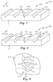
- second major side 200 may comprise a hand-tear pattern 203 that, for example, comprises lines of weakness 210 in the form of grooves (valleys) 217 interspersed between ridges 216, e.g. as shown in the exemplary embodiments of Figs. 5 and 6 .
- valleys 217 comprise recesses, and for purposes of determining whether a given valley is microstructured, its depth can be considered to be the distance (measured normal to the plane of backing 2) from the outwardmost tip of ridge 216 to the inwardmost (deepest) point 214 of valley 217, and its width can be considered to be the distance (measured parallel to the plane of backing 2) from a tip of a ridge 216 to the tip of an adjacent ridge 216.
- ridges 216 and valleys 217 do not necessarily have to have sharp peaks and floors, respectively.
- either or both can be rounded, as in the exemplary embodiment of Fig. 6 , or can have flat valley floors and/or ridge tops, etc.
- any microstructured pattern with an undulating (e.g. fluted, corrugated, etc.) surface that provides at least generally transversely-oriented lines of weakness 210 can be utilized.
- a recess that provides a continuous line of weakness 210 may comprise a continuous elongate groove 211 that extends continuously from one minor edge 11 of backing 2 to other minor edge 12 of backing 2.
- the depth of groove 211 may be at least about 10 microns, at least about 15 microns, or at least about 20 microns.
- the depth of groove 211 may be at most about 60 microns, at most about 50 microns, or at most about 40 microns.
- the width of groove 211 may be at least about 20 microns, at least about 40 microns, or at least about 60 microns.
- the width of groove 211 may be at most about 140 microns, at most about 120 microns, or at most about 100 microns.
- the width of groove 211 may be constant along the length of groove 211, or it may vary along the length.
- the center-to-center spacing between grooves 211 (in the longitudinal direction down backing 2) may be at least about 0.40 mm, at least about 0.60 mm, or at least about 0.80 mm.
- the spacing of grooves 211 may be at most about 1.4 mm, at most about 1.2 mm, or at most about 1.0 mm
- the spacing between grooves 211 may be constant down the length of backing 2, or may vary.
- Grooves 211 may be interspersed (in the longitudinal direction down backing 2) by generally flat portions of surface 215 (as in Figs. 1 and 3 ) or by outwardly-protruding ridges 216, or both, and/or by any other features.
- Grooves 211 may comprise optional features if desired, such as bridging structures 212 as shown in Figs. 8 and 9 .
- bridging structures 212 As shown in Figs. 8 and 9 .
- Such bridging structures which are integrally molded with hand-tear pattern 203 and backing 2, may be spaced periodically down the length of groove 211, and may extend across at least a portion of the lateral width of groove 211 (e.g., in a direction generally aligned with the longitudinal axis of backing 2).
- Such bridging structures may e.g.
- bridging structure 212 may be designed as illustrated in Fig. 8 and shown in magnified view in Fig. 9 .
- bridging structure 212 may comprise two major sloping surfaces 213 that meet at a topmost ridge that is oriented substantially laterally across the width of groove 211.
- bridging structure 212 may have any suitable design (e.g., with a generally flat outward-facing (top) surface, with a rounded top surface, etc).
- lines of weakness 210 may be discontinuous, that is, provided not by a single recess but rather by a multiplicity of (e.g., two or more) recesses, spaced along a long axis (which may be, but does not necessarily have to be, a generally linear or strictly linear path) of discontinuous line of weakness 210 is that oriented at least generally transversely to backing 2, and acting in combination.
- discontinuous grooves 221 may be provided that are interrupted by gaps (e.g., bearing plano surface 215) and that thus do not extend continuously across the entire width of backing 2.
- a discontinuous line of weakness 210 is provided collectively by a multiplicity of elongate oval recesses 222 that are aligned generally linearly across the transverse width of backing 2, each oval recess comprising a long axis that is generally oriented across the transverse width of backing 2.
- recesses 223 comprise diamond-shaped recesses aligned generally linearly across the transverse width of backing 2, each diamond-shaped recess comprising a long axis that is generally oriented across the transverse width of backing 2. It should be noted that such approaches do not necessarily require that individual recesses comprise a long axis that is generally oriented across the transverse width of backing 2, however.
- lines of weakness 210 are collectively provided by rows of generally circular recesses 224. (In Fig. 13 and in Figs. 7-12 , the deepest-inward point of a recess is designated by the reference number 214).
- the depth of a recess may be at least about 10 microns, at least about 15 microns, or at least about 20 microns. In further embodiments, the recess depth may be at most about 60 microns, at most about 50 microns, or at most about 40 microns. If a recess has a long axis, the width of the recess may be constant along the length of the recess (as in Fig. 10 ), or it may vary along the length (as in Figs. 11 and 12 ).
- the width of a recess (which may be measured at any suitable location of the recess, and may be the diameter in the case of a generally circular recess) may be at least about 20 microns, at least about 40 microns, or at least about 60 microns. In further embodiments, the width of a recess may be at most about 140 microns, at most about 120 microns, or at most about 100 microns. In various embodiments, the edge-to-edge spacing between nearest edges of adjacent recesses of a discontinuous line of weakness (e.g., as measured generally along the transverse axis of backing 2) may be at least about 10 microns, at least about 20 microns, or at least about 30 microns. In further embodiments, the edge-to-edge spacing between recesses may be at most about 200 microns, at most about 100 microns, or at most about 60 microns.
- the depth of an individual recess may vary; and/or different recesses may comprise different depths (whether variable or constant).
- Recesses may be of different widths or of the same width.
- a recess width may vary along its inward-outward depth relative to the plane of backing 2 (e.g., when viewed in cross section), e.g. so that it is tapered as in grooves 211 of Fig. 1 , and/or a recess can be any suitable shape when viewed in cross section.
- a recess may comprise a constant width along its depth, may comprise a flat bottom, an arcuate bottom, etc., and/or flat walls, sloped walls, arcuate walls etc.
- the recess may or may not be symmetric when viewed in cross section. All that is required is that the recesses be designed and arranged with appropriate geometry (e.g., depths, widths, spacings, etc.) so as to, individually or collectively, provide a line of weakness 210 that imparts the herein-described ability to hand-tear backing 2 at least generally transversely across its width.
- lines of weakness are continuous or discontinuous (with mixtures of both being encompassed within the disclosures herein), the spacing between individual lines of weakness 210 may be constant down the length of backing 2, or may vary. All of the lines of weakness do not have to be oriented at the same angle (e.g.,. relative to the transverse axis of backing 2). Furthermore, it should be noted that the concept of a multiplicity of lines of weakness as disclosed herein does not imply that the recess or recesses that individually or collectively provide a particular line of weakness 210 must necessarily be aligned strictly in a straight line.
- a continuous line of weakness 210 may be provided by a continuous groove that is somewhat arcuate, wavy, sinusoidal, sawtooth, or the like, as long as its overall path is at least generally transversely across backing 2 in the manner disclosed above.
- a multiplicity of recesses arranged along a somewhat arcuate, wavy, sinusoidal, sawtoothed etc. path may likewise provide a discontinuous line of weakness 210.
- a generally linear, or strictly linear, path may be desired.
- Lines of weakness 210 as described herein thus may enhance or promote the ability of backing 2 to be torn by hand in such a way that the propagating tear is steered in a desired (e.g., an at least generally transverse) direction, e.g. along a desired path.
- a desired e.g., an at least generally transverse
- the propagation of a tear may not be directly along a strictly straight-line path.
- a tear may propagate along one line of weakness for a portion of the way across the transverse width of backing 2, and may then jump to a second, adjacent line of weakness (e.g., a recess thereof) and then continue propagating transversely along the second line of weakness, and so on.
- a second, adjacent line of weakness e.g., a recess thereof
- Such phenomena may be acceptable as long as it does not cause the tear propagation to unacceptably deviate from a desired (e.g. an at least generally transverse) path across the width of backing 2.
- the concept of a multiplicity of lines of weakness is used broadly herein, and encompasses cases in which it may not necessarily be easy, or possible, to discern exactly which particular line of weakness may be followed when backing 2 is hand-torn.
- microstructured recesses individually or collectively, are capable of causing a tear to initiate and propagate at least generally transversely across the width of backing 2 as described herein. In some embodiments, of course, it may be preferred that the tear progression occur generally, or completely, along a single line of weakness.
- lines of weakness 210 may enhance the ability of a hand-tear to be initiated, in addition to enhancing the ability of a propagating hand-tear to be steered in a desired direction.
- a recess that comprises at least a portion of a line of weakness to be present at minor edge 11 of backing 2, and likewise for a recess to be present at minor edge 12 of backing 2.
- This may be provided, for example, by a line of weakness that is a continuous groove (such as, e.g., exemplary groove 211 of Figs. 1-3 ) that extends to minor edges 11 and 12 of backing 2.
- the multiplicity of recesses that make up the line of weakness may be arranged such that a recess is present at minor edge 11 of backing 2, and that a recess is likewise present at minor edge 12 of backing 2.
- a line of weakness 210 is provided that extends across the entire transverse width of second major side 200 of backing 2, from one minor edge 11 to other minor edge 12.
- microstructured paint-retention pattern 103 is meant that first major side 100 of backing 2 tape 1 comprises a multiplicity of microreceptacles 101 that are defined (i.e., bounded, whether continuously or discontinuously) by microstructured partitions 102 (e.g., as shown in exemplary manner in Figs. 1 and 3 ) and that are configured to capture and/or retain liquid paint that impinges upon first major side 100 of tape 1.
- microreceptacles 101 are (e.g.
- each microreceptacle 101 may comprise an area of at least 10,000 square microns, at least about 15,000 square microns, or at least about 20,000 square microns.
- each microreceptacle 101 may comprise an area of at most about 700,000 square microns, about 400,000 square microns, about 100,000 square microns, or about 70,000 square microns.
- microstructured partitions is meant that partitions 102 (which may be continuous or discontinuous, as discussed in detail herein) each comprise a predetermined, molded structure (e.g., as obtained by molding a polymeric thermoplastic resin against a tooling surface that comprises the negative of the features desired to be provided on first major side 100 of backing 2).
- molded structures and features as defined herein are distinguished from features that are achieved by post-processing (e.g., by coating, depositing, ablation, perforation, punching, drilling, and the like).
- microstructured partition is also meant that a partition 102 comprises a height ranging from about 10 microns to about 120 microns. In this context the partition height may often be the distance from major surface 15 of major side 100 of backing 2, to the outwardly-most extending portion of a partition, measured along an axis normal to the plane of backing 2.
- microstructured partition is further meant that a partition has a dimension ranging from about 5 microns to about 200 microns along at least one axis that is orthogonal to the plane of backing 2.
- the partition height i.e. the distance by which outwardmost portion (top) 111 of rib 120 is spaced outwardly away from (above) first major surface 15 of backing 2, along an axis normal to the major plane of backing 2, may be in the range of 10 to 120 microns.
- the lateral width of rib 120 (measured at any point, ranging from the base 112 to the top 111 of rib 120) may be in the range of about 5 microns to about 200 microns. If so, rib 120 is by definition a microstructured feature irrespective of the fact that it may have an extremely long length. In some embodiments, microstructured partitions 102 are present in regular, predictable, repeating patterns.
- the height of partitions 102 may be at most about 120 microns, at most about 100 microns, at most about 90 microns, or at most about 80 microns. In further embodiments, the height of partitions 102 may be at least about 20 microns, at least about 30 microns, or at least about 40 microns. In various embodiments, at least some of partitions 102 may be tapered (e.g., as shown in exemplary illustration in Fig. 1 ) so as to comprise a top with at least one dimension, e.g.
- ribs 120 and/or ribs 133 may be tapered, as in Fig. 1 , so that their width at tops 111/131 is less than about 80% of their width at bases 112/132, respectively.
- the top of partitions 102 e.g., as exemplified by tops 111 and 131 of elongate ribs 120 and 133, respectively
- major surface 15 of first major side 100 of backing 2, from which partitions 102 protrude may comprise a generally plano (flat) surface.
- major surface 15 of backing 2 within one or more microreceptacles 101 may comprise optional secondary features.
- Such secondary features may comprise e.g. one or more protruding features of e.g. 10 microns or less in height (such as, e.g. riblets 118 as shown in exemplary manner in Fig. 20 , but also possibly comprising posts, mounds, bumps, and the like), e.g. located within one or more microreceptacles 101 and protruding from major surface 15 therewithin.
- Recessed secondary features, and/or mixtures of protruding and recessed secondary features may also optionally be present.
- such secondary features may cause the bottom (e.g., floor) of a microreceptacle 101 to comprise an increased surface area, an increased surface roughness, etc., which may e.g. enhance the anchorage of paint within microreceptacle 101 in some instances.
- a plano major surface 15 may be used as a reference plane for purposes of determining the height of a partition 102.
- major surface 15 may not be flat; e.g., it may comprise a somewhat rough surface (which may be a regular or irregular pattern) with no easily discernible plano surface. If so, the height of a partition 102 may be measured relative to the average plane of such an irregular or variable major surface.
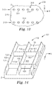
- Microstructured partitions 102 may comprise a multiplicity of first elongate partitions 110 that may not physically intersect with each other, and a multiplicity of second elongate partitions 130 that may not physically intersect with each other, with at least some of first partitions 110 intersecting with at least some of second partitions 130 at intersections 150 so as to define microreceptacles 101 thereby.
- Such intersecting of first partitions 110 with second partitions 130 may comprise actual physical intersections of first and second partitions 110 and 130, as with intersections 150 of Figs. 1 and 14 .
- Such an intersection of first partitions 110 with second partitions 130 may comprise the intersecting of paths followed by discontinuous partitions, as with intersections 150 of first partitions 110 and second partitions 130 in Figs. 18 and 19 (discussed in detail later herein).
- such an intersection of first partitions 110 with second partitions 130 may comprise a point in space rather than an actual physical portion of a partition.
- first partitions 110 may follow paths such that the individual first partitions 110 do not physically intersect with each other, and second partitions 130 may follow paths such that the individual second partitions 130 do not physically intersect with each other.
- first partitions 110 may be strictly linear and parallel to each other along substantially their entire elongate length; likewise, second partitions 130 may be strictly linear and parallel to each other along substantially their entire elongate length.
- at least some of first partitions 110 may be nonlinear (e.g., may follow a path that is arcuate, sinusoidal, etc.) but may be locally parallel to each other (e.g., at their points of closest approach to each other), as may second partitions 130.
- first partitions 110 may not be locally parallel, but may still follow overall paths so that the individual first partitions 110 do not intersect with each other, as may second partitions 130.
- the spacings between first partitions 110 may be constant, the spacings between second partitions 130 may be constant, and the first and second partition spacings may be the same (i.e., so that microreceptacles 101 are square), as in the exemplary designs of Figs. 1 and 3 .
- first partitions 110 may be spaced different distances from each other than second partitions 130 are spaced from each other (i.e., microreceptacles 101 defined by partitions 110 and 130 may be rectangular rather than square). The spacings between individual partitions 110, and/or between individual partitions 130, may vary rather than being constant.
- first elongate partitions 110 may be provided so that their elongate lengths (long axes) are generally orthogonal to the elongate lengths of second partitions 130 (whether partitions 110 and/or 130 are continuous or discontinuous along their elongate lengths, as discussed in detail later herein), e.g. as in the exemplary embodiment of Figs. 1 and 3 .
- the terminology of generally orthogonal is used broadly and is not intended to limit to a case in which first and second partitions 110 and 130 are aligned strictly at right angles to each other. Rather, generally orthogonal encompasses any angle between 70 and 110 degrees (e.g., such that microreceptacles 101 may be somewhat diamond-shaped rather than square).
- the angle between first and second partitions may be between 80 and 100 degrees, or between 88 and 92 degrees (e.g., so as to provide square microreceptacles 101).
- First and second partitions 110 and 130 of first major side 100 of backing 2 may be provided at any convenient orientation with regard to lines of weakness 210 of second major side 200 of backing 2.
- some or all of second partitions 130 may be substantially aligned with lines of weakness 210, meaning having a long axis that is oriented within plus or minus about 20 degrees of the long axis of lines of weakness 210.
- some or all of second partitions 130 may have a long axis that is oriented within plus or minus about 10 degrees of the long axis of lines of weakness 210.
- second partitions 130 may be in strict alignment with lines of weakness 210, meaning having a long axis that is oriented within plus or minus about 5 degrees of the long axis of lines of weakness 210. It will be appreciated that designs in which second partitions 130 are e.g. substantially aligned, or strictly aligned, with lines of weakness 210, may enhance the ability of backing 2 to be hand-torn along a line or lines of weakness 210. That is, such arrangements may minimize the number of second partitions 130 that must be torn through (broken) in order to hand-tear backing 2 along a line or lines of weakness 210.
- First and second partitions 110 and 130 may be provided at any convenient orientation with regard to the longitudinal and transverse axes of backing 2. However, in some embodiments some or all of second partitions 130 may be oriented at least generally transversely to backing 2, meaning having a long axis that is oriented within plus or minus about 45 degrees of the transverse axis of backing 2. In further embodiments, some or all of second partitions 130 may be oriented within plus or minus about 30 degrees, plus or minus about 20 degrees, or plus or minus about 10 degrees, of the transverse axis of backing 2.
- some or all second partitions 130 may be in strict alignment with the transverse axis of backing 2, meaning having a long axis that is oriented within plus or minus about 5 degrees of the transverse axis of backing 2 (e.g., as exemplified by partitions 130 of Figs. 1 and 3 ).
- a partition does not necessarily need to be continuous to have a long axis, as will be apparent from later discussions herein. It will also be appreciated that any condition regarding the angular alignment (orientation) of partitions relative to lines of weakness, does not require that the partitions be placed at any particular position (e.g. along the longitudinal axis of backing 2) relative to lines of weakness 210.
- lines of weakness 210 may be longitudinally spaced at e.g. 800 microns
- partitions 130 may be longitudinally spaced at e.g. 150 microns.
- some partitions 130 may have a line of weakness directly opposite them through the thickness of backing 2, while other partitions 130 may be positioned opposite spaces in between adjacent lines of weakness on the opposite side of backing 2. That is, it is not required that lines of weakness of the second major side, and partitions of the first major side, have the same spacing and/or are in registration with each other, although this may be done if desired.
- second partitions 130 may enhance the ability of backing 2 to be hand-torn at least generally transversely across the width of backing 2. That is, such arrangements may minimize the number of second partitions 130 that must be torn through (broken) in order to hand-tear backing 2 across its transverse width. Designs in which second partitions 130 are oriented strictly transversely to backing 2 may likewise enhance the ability of backing 2 to be hand-torn in a direction strictly transverse to backing 2.
- first partitions 110 may be at least generally longitudinally aligned with backing 2, meaning having a long axis that is oriented within plus or minus about 45 degrees of the longitudinal axis of backing 2. In further embodiments, some or all of first partitions 110 may be oriented within plus or minus about 30 degrees, plus or minus about 20 degrees, or plus or minus about 10 degrees, of the longitudinal axis of backing 2. In a specific embodiment, some or all first partitions 110 may be in strict alignment with the longitudinal axis of backing 2, meaning having a long axis that is oriented within plus or minus about 5 degrees of the longitudinal axis of backing 2 (e.g., as exemplified by partitions 110 of Figs. 1 and 3 ).
- first partitions 110, and second partitions 130 may each comprise continuous, elongate ribs (as exemplified by first elongate ribs 120 and second elongate ribs 133 of Figs. 1 and 3 ).
- first major side 100 of backing 2 may comprise a multiplicity of first partitions 110, each partition 110 comprising a continuous rib 120 with base 112 and top 111, with a height, width, and an elongate length, and with the elongate length being generally, e.g. strictly, aligned with the longitudinal axis of backing 2 and of tape 1.
- First major side 100 of backing 2 may additionally comprise a multiplicity of second partitions 130, each partition 130 comprising a continuous rib 133 with base 132 and top 131, with a height, width, and an elongate length, and with the elongate length (long axis) being generally, e.g. strictly, aligned with the transverse axis of backing 2 and of tape 1.
- elongate ribs 120, and elongate ribs 133 may each comprise a uniform height that does not vary along the length of the rib.
- the height of ribs 120 may be equal to that of ribs 133, again as shown in Fig. 1 .
- first partitions 110 may be designed so as to enhance the ability of backing 2 to be hand-torn at least generally along the transverse axis "T" of the backing. For example, if first partitions 110 are e.g. generally, or strictly, aligned with the longitudinal axis "L" of backing 2, at least some of these partitions may need to be torn during the at least generally transverse hand-tearing of tape 1 (in contrast to e.g. second partitions 130 that may be generally or strictly aligned with transverse axis "T" and thus may be aligned at least generally parallel to the tear direction and thus may not need to be torn during the at least generally transverse hand-tearing of tape 1). At least some of first partitions 110 may thus be designed and/or arranged so as to minimize the resistance to hand-tearing that they provide.
- first (generally longitudinally-oriented) elongate ribs 120 may be shorter in height than second elongate ribs 133. Such shorter ribs may present less resistance to being torn through in the process of hand-tearing the backing at least generally transversely across its transverse width.
- each first rib 120 may comprise a uniform height, with the uniform height being less than about 80 %, or less than about 60 %, of the height of second ribs 133.
- each first rib 120 may comprise a uniform height that is at least about 20 %, or at least about 40 %, of the height of second ribs 133.
- ribs 133 may be of around 70 microns in height and ribs 120 may be around 50 microns in height. All such segments of all such ribs 120 may be at this lower height (with a segment of a rib 120 meaning a length of the rib between its intersections 150 with second ribs 133), as in the exemplary embodiment of Fig. 14 .
- only certain ribs, or certain segments of ribs might be at such a lower height.
- only every second, third, fourth or fifth rib 120 may be at such a lower height.
- first ribs 120 may be (in addition to, or instead of, being shorter in height than second ribs 133 ), narrower in thickness than second ribs 133; e.g. toward their base, toward their top, and/or any portions therebetween, which may also enhance the ability of backing 2 to be at least generally transversely hand-torn.
- first partitions 110 may be configured to enhance the ability of backing 2 to be at least generally transversely hand-torn is shown in exemplary manner in Fig. 15 .
- first ribs 120 may be provided in which continuous rib segments (i.e., segments that extend continuously between intersections 150 with second ribs 133) comprise smoothly varying profiles such that the height of a portion of rib 120 at a location 113 that is between its intersections 150 and is distal to intersections 150 (e.g., that is approximately halfway between intersections 150) is less than the height of the rib segment at points adjacent its intersections 150 with second ribs 133.
- the heights of ribs 120 at locations 113 distal to intersections 150 may be less than 80% of, less than 70% of, or less than 60% of, the heights of ribs 120 at locations adjacent intersections 150 with second ribs 133.
- the height of some or all of ribs 120 may, at their intersections 150 with ribs 133, be generally the same as the height of ribs 133 (as in the exemplary design of Fig. 15 ), or may be less than (e.g., no more than 80% of) the height of ribs 133.
- second ribs 133 may likewise comprise smoothly varying profiles such that the height of rib portions at locations between intersections with first ribs 120 is less than that at points adjacent intersections with first ribs 120 (e.g. as in the Representative Working Example presented later herein).
- first partitions 110 may be configured to enhance the ability of backing 2 to be at least generally transversely hand-torn is shown in exemplary manner in Fig. 16 .
- at least one notch 114 is provided in a portion of a segment of rib 120.
- Notch 114 (which may be V-shaped, square-bottomed, etc.) may comprise a lowest point at which the local height of rib 120 is less than about 80% of the height of rib 120 at locations adjacent rib 120's intersections 150 with ribs 133.
- the depth of notch 114 may be chosen so that this local rib height is less than about 80%, less than about 60%, less than about 40%, or less than about 20%, of the height of rib 120 at locations adjacent rib 120's intersections 150 with ribs 133.
- the exemplary design of Fig. 17 comprises discontinuous partitions 110 in the form of discontinuous ribs 121.
- a discontinuous rib means one comprising at least one gap in which major surface 15 of first major side 100 of backing 2 is visible (noting that partitions 110 e.g. in the form of ribs 120 as in Fig. 1 are defined as continuous, notwithstanding their intersections 150 with partitions 130).
- one such gap 115 is provided in each segment of discontinuous ribs 121.
- a further variation of such an approach is shown in exemplary manner in plan view in Fig. 18 , in which first partitions 110 comprise discontinuous partitions in the form of outwardly-protruding posts 116.
- posts 116 can be of any convenient shape.
- posts 116 may, if appropriately designed and spaced, collectively function as a partition 110 (e.g., in a "picket fence" manner), to at least a sufficient extent to satisfactorily prevent or minimize the passage of liquid paint.
- partitions 102 it is not necessary that both, or even either, of partitions 102 must be continuous.
- still another potential design is shown in exemplary manner in Fig. 19 , in which not only the first partitions 110 are discontinuous (as provided by posts 116), but second partitions 130 are as well (as provided by posts 117).
- a set of posts does not necessarily have to be positioned in a strictly linear format (e.g., as in Figs. 15 and 16 ). Rather, the posts could be provided in a curved, sinusoidal, staggered, zig-zag, etc. format, as long as the posts are e.g. sufficiently close to each other and of sufficient height and size (e.g., width or diameter) to collectively provide a partition 102. Although shown as circular in Figs 18 and 19 , such posts may be any convenient shape.
- a notch 114 or gap 115 in one or more ribs 120 may be the same height as ribs 133, or may be a lower height.
- a rib 133 may comprise a generally uniform height, or may have an arcuate profile similar to that shown in Fig. 15 .
- Not all ribs 133 need be identical, of course.
- a segment of a first rib 120 comprises portions of generally constant and equal height, that are interrupted by notch 114 that comprises the lowest rib height, and a design of the type shown in Fig. 15 in which a segment of a first rib 120 comprises a height that decreases more or less smoothly and continuously to a point 113 that comprises the lowest rib height.
- first partitions 110 may comprise ribs of a relatively low height and/or may comprise notches, gaps and/or discontinuities, with only a certain remaining number of ribs having a relatively high height and/or not comprising notches, gaps, discontinuities, etc. These remaining ribs may be spaced apart from each other by intervening lower/notched/gapped and/or discontinuous ribs.
- first partitions may enhance the widthwise hand-tearability of backing 2, while the occasional, spaced-apart first partitions that are higher and/or that do not comprise notches, gaps or discontinuities, may ensure that the paint-retention pattern 103 still satisfactorily captures and retains paint.
- first partitions 110 any such features and designs might also be employed with second partitions 130, if desired.
- other features e.g., the aforementioned secondary structures
- microreceptacles 101 can be provided within microreceptacles 101, e.g. protruding from major surface 15 of backing 2, as desired for particular purposes.
- Backing 2 and microstructured paint-retention pattern 103 of first major side 100, and microstructured hand tear pattern 203 of second major side 200, are defined herein as constituting a monolithic plastic unit made of a monolithic plastic material.
- partitions 102 that define microstructured paint-retention pattern 103 are integrally connected to backing 2 and were formed by being molded therewith.
- a monolithic plastic unit may be conveniently formed e.g. by providing a polymeric thermoplastic film or a molten polymeric thermoplastic extrudate and molding both major surfaces (e.g., simultaneously) so as to form backing 2, partitions 102 that define microstructured paint-retention pattern 103, and the recesses that provide lines of weakness 210 of microstructured hand-tear pattern 203, all at the same time, as an integral unit.
- the overall thickness of backing 2 from second major surface 215 of second major side 200, to the outermost portion of partitions 102 (e.g., to the tops 111 and 131 of ribs 120 and 133, respectively, with respect to the exemplary embodiment of Fig. 1 ), may be at least about 25 microns, at least about 50 microns, at least about 60 microns, or at least about 70 microns. In further embodiments, the overall thickness of backing 2 may be at most about 250 microns, at most about 140 microns, at most about 120 microns, or at most about 100 microns.
- the material that comprises backing 2 the material that comprises partitions 102 that define microstructured paint-retention pattern 103 of first major side 100, and the material whose surfaces define the recesses (e.g., grooves, valleys, holes, etc.) that provide lines of weakness 210 of hand-tear pattern 203 of second major side 200, are all of the same composition.
- the plastic material of backing 2 is by definition a moldable polymeric thermoplastic material that is not a foamed or porous material.
- the plastic material may be noncellulosic, meaning that it contains less than about 5 wt. % cellulosic material (e.g., cellulose, paper, regenerated cellulose, wood fibers, wood flour, etc., with, in this context, cellulose acetate and the like not considered to be cellulosic materials).
- the plastic material may be melt-processable, e.g. extrudable.
- the moldable polymeric thermoplastic material may be made from, or include, any of a variety of materials.
- thermoplastic polymers may include, for example, polyolefins such as polypropylene or polyethylene; polystyrene, polycarbonate, polymethyl methacrylate, ethylene vinyl acetate copolymers, acrylate-modified ethylene vinyl acetate polymers, ethylene acrylic acid copolymers, nylon, polyvinylchloride, and engineering polymers such as polyketones or polymethylpentanes. Mixtures of such polymers may also be used.
- the plastic material may be a polyolefinic material, defined herein as being any homopolymer, copolymer, blend, etc., of any olefinic polymers (e.g., polyethylenes, polypropylenes, and so on).
- the polyolefinic material may contain at least about 90 wt. %, at least about 95 wt. %, or at least about 98 wt.% of polyethylenes, not counting the weight of any mineral fillers that may be present.
- polyethylenes are meant polymers comprised of at least 95 % ethylene units.
- the polyethylenes are ethylene homopolymers.
- the polyolefinic material may consist essentially of ethylene homopolymers, noting that this requirement (in addition to not including the weight of any mineral fillers) does not preclude the presence of processing aids, plasticizers, antioxidants, colorants, pigments, and the like, at least some of which may contain some small level of non-polyethylene polymers.
- the polyolefinic material may contain substantially no polypropylene, as well as substantially no non-olefinic polymers. (Those of ordinary skill will appreciate that as used herein, the term "substantially no” does not preclude the presence of some extremely low, e.g. 0.5% or less, amount of material, as may occur e.g. when using large scale production equipment subject to customary cleaning procedures.)
- Suitable polyethylene homopolymers for use in backing 2 may include e.g. high-density polyethylene, medium-density polyethylene, low-density polyethylene, linear low-density polyethylene, ultra-low-density polyethylene, and the like.
- the polyethylene homopolymers may consist essentially of a blend of low density polyethylene (LDPE, i.e. having a density of between 0.88 g/cc and 0.93 g/cc) and high density polyethylene (HDPE, i.e. having a density of between 0.94 g/cc and 0.97 g/cc), at a weight ratio of from about 90:10 LDPE:HDPE to about 10:90 LDPE:HDPE.
- LDPE low density polyethylene
- HDPE high density polyethylene
- the weight ratio of LDPE to HDPE may be from about 70:30 to about 30:70, from about 60:40 to about 40:60, or from about 55:45 to about 45:55.
- the LDPE/HDPE blend may comprise one or more inorganic (e.g., particulate mineral) fillers, which may include e.g. calcium carbonate, kaolin, talc, silica, titanium dioxide, glass fibers, glass bubbles, and the like. Such fillers may be present e.g. at from about 2% to about 20% by weight of the total weight of the material of backing 2. Other additives may be included as desired for particular purposes.
- Extruder 430 can be used to extrude molten polymeric thermoplastic extrudate 431, one major surface of which then contacts tooling roll 410, which roll bears on its surface the negative of the desired features to be imparted to first major side 100 of backing 2. Additionally the opposing major surface of extrudate 431 contacts tooling roll 420, which roll bears on its surface the negative of the desired features to be imparted to second major side 200 of backing 2. Conveniently, the contacting may be done essentially simultaneously, e.g. by impinging molten extrudate 431 into a narrow gap (nip) in between rolls 410 and 420.
- nip narrow gap
- tooling surfaces as may be provided by tooling belts, platens, and the like, can be used if desired.
- the tooling surfaces may be metal (e.g., in the form of metal rolls), or may comprise softer materials, e.g. silicone belts, or polymeric sleeves or coatings disposed upon metal backing rolls).
- Such tooling surfaces, with the negative of the desired features thereon, may be obtained e.g. by engraving, knurling, diamond turning, laser ablation, electroplating or electrodeposition, or the like, as will be familiar to those of skill in the art.
- tooling rolls e.g. metal tooling rolls
- the metal tooling rolls may be maintained at temperature of between about 30 degrees C and about 79 degrees C, or between about 60 degrees C and about 71 degrees C.
- the extrudable compositions may have a Melt Flow Index of between about 1 and 20, or between about 5 and 15. If desired, rather than molten extrudate 431, a pre-existing moldable polymeric thermoplastic film can be heated and contacted with tooling surfaces to mold the desired microstructured patterns on the major surfaces thereof.
- Molten extrudate 432 that has been contacted with tooling surfaces so as to impart paint-retention pattern 103 to first major side 100 and hand-tear pattern 203 to second major side 200 can be solidified so as to form backing 2 with paint-retention pattern 103 and hand-tear pattern 203 upon the major surfaces thereof, as a monolithic plastic unit. It may be convenient that the molded extrudate be held in contact with a tooling surface, e.g. of a tooling roll, e.g. by following a path around significant portion of the roll as shown in exemplary manner in Fig. 21 , to allow such solidification. If desired, a takeoff roll 425 may be provided to assist in the handling of the molded, solidified backing 2 upon its removal from a tooling roll.
- Pressure-sensitive adhesive 300 can then be disposed on second major side 200 of backing 2, e.g. by using coater 433.
- the deposition of pressure-sensitive adhesive 300 can be inline in the same process as the molding, as in the exemplary configuration of Fig. 21 . Or, it can be done off-line, in a separate process.
- Pressure-sensitive adhesive (layer) 300 can be deposited onto second major side 200 by any suitable process, including for example coating methods including solvent coating methods or hot melt coating methods, e.g. knife coating, roll coating, reverse roll coating, gravure coating, wire wound rod coating, slot orifice coating, slot die coating, extrusion coating, or the like. In many cases such processes may involve the deposition of a pressure-sensitive adhesive precursor onto second major side 200 of backing 2 and then transforming the precursor into pressure-sensitive adhesive 300 (e.g., by removal of solvent, by curing or crosslinking, etc.).
- coating methods including solvent coating methods or hot melt coating methods, e.g. knife coating, roll coating, reverse roll coating, gravure coating, wire wound rod coating, slot orifice coating, slot die coating, extrusion coating, or the like.
- such processes may involve the deposition of a pressure-sensitive adhesive precursor onto second major side 200 of backing 2 and then transforming the precursor into pressure-sensitive adhesive 300 (e.g., by removal of solvent, by curing or crosslinking, etc
- pressure-sensitive adhesive 300 onto second major side 200 so that the adhesive is not only in intimate contact with, and adhesively bonded to, second major surface 215 of backing 2, but so that the adhesive also penetrates into the recesses that form lines of weakness 210, and is in intimate contact with, and adhesively bonded to, the surfaces (e.g., walls, floor, etc.) of the recesses. Furthermore, it may be desirable to provide pressure-sensitive adhesive 300 at a thickness, relative to the depth of the recesses, such that the outward-facing surface 301 of adhesive 300 is generally flat even in the areas of adhesive 300 overlying the recesses of second major side 200 of backing 2 (e.g., rather than exhibiting depressions in those areas).
- the thickness of pressure-sensitive adhesive 300 may be at least about 20 microns, at least about 30 microns, or at least about 40 microns. In further embodiments, the thickness of pressure-sensitive adhesive 300 may be at most about 100 microns, at most about 80 microns, or at most about 60 microns.
- pressure-sensitive adhesive 300 Any suitable pressure-sensitive adhesive material or composition can be used in pressure-sensitive adhesive 300.
- Pressure-sensitive adhesives are normally tacky at room temperature and can be adhered to a surface by application of, at most, light finger pressure and thus may be distinguished from other types of adhesives that are not pressure-sensitive.
- a general description of useful pressure-sensitive adhesives may be found in Encyclopedia of Polymer Science and Engineering, Vol. 13, Wiley-Interscience Publishers (New York, 1988 ). Additional description of useful pressure-sensitive adhesives may be found in Encyclopedia of Polymer Science and Technology, Vol. 1, Interscience Publishers (New York, 1964 ). It may be convenient that the adhesive material be chosen so as to provide good adhesion to a surface, while also being removable under moderate force without leaving a residue, e.g. a visible residue.
- suitable materials for the pressure-sensitive adhesive may include e.g. polymers based on acrylate and/or methacrylate materials, natural or synthetic rubbers, block copolymers, silicones, and so on.
- Suitable polymers and/or monomer units therein may include, but are not limited to: polyvinyl ethers, polyisoprenes, butyl rubbers, polyisobutylenes, polychloroprenes, butadiene-acrylonitrile polymers, styrene-isoprene, styrene-butylene, and styrene-isoprene-styrene block copolymers, ethylene-propylene-diene polymers, styrene-butadiene polymers; poly-alpha-olefins, amorphous polyolefins, polysiloxanes, ethylene vinyl acetates, polyurethanes, polyvinylpyrrolidones, and any combinations thereof
- suitable (meth)acrylate materials include polymers of alkyl acrylate or methacrylate monomers such as e.g. methyl methacrylate, ethyl methacrylate, n-butyl methacrylate, methyl acrylate, ethyl acrylate, n-butyl acrylate, iso-octyl acrylate, iso-nonyl acrylate, 2-ethyl-hexyl acrylate, decyl acrylate, dodecyl acrylate, n-butyl acrylate, hexyl acrylate, and combinations thereof.
- alkyl acrylate or methacrylate monomers such as e.g. methyl methacrylate, ethyl methacrylate, n-butyl methacrylate, methyl acrylate, ethyl acrylate, n-butyl acrylate, iso-octyl acrylate, iso-non
- the adhesives can contain additives such as tackifiers, plasticizers, fillers, antioxidants, stabilizers, pigments, and the like.
- tape 1 may be conveniently provided in the form of a roll 20 as shown in exemplary manner in Fig. 2 .
- tape 1, and roll 20 thereof do not include any kind of release liner (e.g., a paper or plastic film bearing a release surface, whether supplied by the film itself or by a low-energy coating thereupon, such release liners being well known in the adhesive arts).
- release liner e.g., a paper or plastic film bearing a release surface, whether supplied by the film itself or by a low-energy coating thereupon, such release liners being well known in the adhesive arts.
- roll 20 is a self-wound roll meaning that it is wound directly upon itself with outward surface 301 of pressure-sensitive adhesive 300 being in releasable contact with the outwardmost surfaces of partitions 102 that define paint-retention pattern 103 of first major side 100 of backing 2.
- pressure-sensitive adhesive 300 would be in releasable contact with at least tops 111 and 131 of ribs 120 and 133 respectively.
- releasable contact is meant that pressure-sensitive adhesive 300 is adhered to the outwardmost surfaces of partitions 102 sufficiently to provide roll 20 with adequate mechanical integrity to acceptably maintain the form of a roll (that is, so that the roll does not unacceptably unroll from its self-wound condition too easily), but so that the adhesive force between pressure-sensitive adhesive 300 and the outwardmost surfaces of partitions 102 is low enough that adhesive 300 can be debonded and separated from the partition surfaces without unacceptable force being necessary and without unacceptably damaging either the partitions or the adhesive or debonding the adhesive from second major side 200 of backing 2.
- This releasable contact may be gauged by way of the force required to unwind tape 1 from its self-wound condition, as measured e.g.
- tape 1 may comprise an unwind force of at least 2, 3, or 4 ounces of force per inch width of tape (0.22, 0.33, or 0.44 N/cm width of tape). In further embodiments, tape 1 may comprise an unwind force of at most 40, 30, or 20 ounces of force per inch width of tape (4.4, 3.3, or 2.2 N/cm width of tape).
- a paint-retention pattern 103 with more closely spaced partitions and/or with partitions with a wider top surface, which would provide an increased surface area for pressure-sensitive adhesive 300 to bond to might advantageously be combined with a relatively weak (e.g., low-tack) pressure-sensitive adhesive composition; conversely, if the partitions are widely spaced and/or have very narrow top surfaces, they might advantageously be combined with a relatively strongly bonding pressure-sensitive adhesive.
- a relatively weak (e.g., low-tack) pressure-sensitive adhesive composition conversely, if the partitions are widely spaced and/or have very narrow top surfaces, they might advantageously be combined with a relatively strongly bonding pressure-sensitive adhesive.
- the bondable surface area of partitions 102 may be provided by top surfaces 111 of first ribs 120 and by top surfaces 131 of second ribs 133.
- first ribs 120 may be sufficiently shorter in height than second ribs 133 that the bondable surface area may be provided only by top surfaces 131 of second ribs 133 (and, e.g., not by top surfaces 111 of first ribs 120).
- Fig. 14 first ribs 120 may be sufficiently shorter in height than second ribs 133 that the bondable surface area may be provided only by top surfaces 131 of second ribs 133 (and, e.g., not by top surfaces 111 of first ribs 120).
- the bondable surface area may be provided by top surfaces 131 of second ribs 133, and by a portion of top surfaces 111 of first ribs 120.
- first ribs 120 and second ribs 133 comprise arcuate shapes (e.g., in which both resemble the shape of first ribs 120 of Fig. 15 ) in which the rib portions at their intersections are the farthest outward-protruding
- the bondable surface area may be provided mainly by the top surfaces of ribs at such intersections.
- the bondable surface area offered by partitions 102 may comprise at least about 1 %, at least about 2%, at least about 5%, at least about 10 %, or at least about 15 %, of the nominal surface area (i.e., length times width) of first major side 100 of backing 2. In further embodiments, the bondable surface area may comprise at most about 35 %, at most about 30 %, or at most about 25 %, of the nominal surface area of first major side 100 of backing 2.
- first major side 100 of backing 2 may comprise, in addition to partitions 102, outwardly protruding bonding features that are specially configured to provide bondable surface areas for pressure-sensitive adhesive 300 but which may not necessarily participate significantly in the process of capturing and/or retaining liquid paint.
- Such bonding features may be provided e.g. in the form of posts that extend outward beyond the outwardmost surfaces of partitions 102 and that comprise bondable areas upon their outwardmost surfaces.
- first major side 100 of backing 2 e.g. at least the outwardmost portions and/or surfaces of partitions 102
- Treatments which may decrease the bonding ability include e.g. the deposition of low surface energy conformal coatings to the outwardmost surfaces of partitions 102.
- Such low surface energy conformal coatings are conveniently available in the form of so-called low adhesion backsizes and the like.
- low adhesion backsize coatings may be applied in such manner (e.g., by gravure coating) that the coating is primarily applied only to the outwardmost surfaces (i.e., the surface areas that are bondable by pressure-sensitive adhesive 300) of partitions 102.
- such coatings may also be applied to surfaces within one or more microreceptacles 101, e.g. a floor surface of a microreceptacle 101, such as may be supplied by major surface 15 of backing 2 within a microreceptacle 101.
- Treatments which may increase the bonding ability may include e.g. corona treatment, plasma treatment, flame treatment, or the like; or, deposition (e.g., coating) of a primer, tie layer, or the like.
- deposition e.g., coating of a primer, tie layer, or the like.
- second major side 200 of backing 2 can be treated so as to enhance the ability of pressure-sensitive adhesive 300 to adhere to it.
- treatment may comprise e.g. corona treatment, plasma treatment, flame treatment, or the like; or, deposition (e.g., coating) of a primer, tie layer, or the like.
- a length of the tape may be removed from an elongate length, e.g. a roll 20, of the tape. This may be performed by hand-tearing the tape across its transverse width, at the desired location, although scissors, a knife, or any other suitable cutting implement may be used if convenient.
- the hand-tearing may be performed by grasping, with each hand, portions of the tape that longitudinally bracket the desired tear location, and moving one portion of the tape in a first direction and the other portion in a generally opposite direction so as to apply shear force at the desired tear location to initiate and propagate a tear at least generally transversely across the width of the tape.
- a terminal portion of the tape may, while still attached to roll 20, be applied and adhered to a desired portion of a surface and then a remaining portion of the elongate length of the tape (e.g., roll 20 itself) may be manipulated (e.g., twisted or translated) so that the non-adhered portion of the tape is at least generally transversely torn in a location e.g. near the closest point at which the tape is adhered to the surface. Both of these methods are well known to those of skill in the art.
- tape 1 may be used in conjunction with a masking film, and may be conveniently applied (e.g., along with such a masking film) to a surface by use of a masking tool, e.g. the product available from 3M Company of St. Paul, MN, under the trade designation 3M HAND-MASKER DISPENSER.
- Tape 1 having been applied to a desired portion of a surface, adjacent portions of surfaces can then be painted as desired (the term paint is used broadly herein and encompasses any coating, primer, varnish, and the like).
- tape 1 can then be removed from the surface.
- Tape 1 can be used to mask any desired surface in preparation for painting with any suitable liquid paint, whether such paint be applied with a sprayer, brush, roller, etc. (In this context a paint sprayer specifically excludes ink-jetting apparatus).
- paint may be e.g. latex or oil-based.
- Such paints may be distinguished from e.g.
- ink-jettable inks and the like which are typically deposited only onto horizontally oriented surfaces (with respect to gravity), in very small volumes (e.g., picoliter-sized droplets).
- the main concern is typically the quality of the formed image (e.g., minimizing the degree to which the deposited very small volumes of different color inks may migrate and/or diffuse into each other in such manner as to blur the colors and/or edges of images).
- tape 1 as disclosed herein has been found to be capable of capturing and retaining gross quantities of paint, including high viscosity (e.g., > 100 cps at 21 degrees C) latex paints, and including when tape 1 is in a vertical orientation.
- the paint-retention patterns disclosed herein exhibit a surprisingly high ability to capture and retain large quantities of liquid paint, as evidenced by the Examples herein. It has also been found that the paint-retention patterns disclosed herein provide paint which had been dried thereupon and/or therein with an enhanced ability to resist flaking off, as evidenced by the Examples herein. In particular, it has been found that dried paint is surprisingly resistant to flaking off of tape 1 even upon the stretching of tape 1 as may occasionally occur during removal of tape 1 from a surface.
- Tape 1 as disclosed herein comprises an additional advantage in at least some embodiments, in that it can be extensively transversely curved (which might be done by some apparatus or device, but may be most likely to be done manually by a user of the tape) if desired.
- to transversely curve an elongate length of tape 1 means to form it into a continuous curved shape that lies in a generally flat plane (e.g., as shown in the digital image of an exemplary transversely curved tape 1 in Fig. 22 ).
- Such an ability may allow a single elongate length of tape 1 to be transversely curved to match a shape or edge (e.g., an edges of an oval or round window) that conventionally might require numerous short, linear lengths of tape to be used in combination, and/or might require lengths of tape to be manually folded, to match.
- a shape or edge e.g., an edges of an oval or round window
- tape 1 to be extensively transversely curved means that at least some portions of backing 2, e.g. those close to one transverse minor edge of backing 2 (e.g., minor edge 12 of Fig. 22 ), must be able to stretch at least somewhat, without rupturing or tearing, upon application of stretching force to these portions of backing 2 in order to transversely curve tape 1.
- first partitions 110 especially if oriented with their long axes generally, e.g. strictly, aligned with the longitudinal axis of backing 2, would resist both tearing and stretching and thus would interfere with both abilities.
- Tape 1 as disclosed herein comprises an additional advantage of being resistant to slivering, e.g. in comparison to conventional paper-based masking tapes. Additionally, tape 1 as disclosed herein may comprise yet another advantage in being less susceptible to undesirable effects of humidity, e.g. in comparison to conventional paper-based masking tapes. Still further additionally, tape 1 as disclosed herein may comprise an enhanced ability to conform to and bond to rough or uneven surfaces, and may provide good paint lines even upon such surfaces.
- tapes bearing a microstructured paint-retention pattern 103 comprising partitions 102 that define microreceptacles 101, have been unexpectedly found to be able to capture and retain large quantities of liquid paint, and to exhibit an enhanced ability to resist flaking off of the dried paint.
- a method of painting a first surface portion while masking a second surface portion so that it is not painted comprising: adhesively attaching a length of plastic tape to the second surface portion, the plastic tape comprising a backing comprising a longitudinal axis and a transverse width and axis, and comprising a first major side and an oppositely-facing second major side, wherein the first major side of the backing comprises a microstructured paint-retention pattern, wherein a pressure-sensitive adhesive is disposed on the second major side of the backing, and wherein the backing and the microstructured paint-retention pattern constitute a monolithic plastic unit; and, applying liquid paint to at least the first surface portion.
- a hand-tear pattern need not necessarily be present (e.g., on the second major side of the backing).
- the major surface of the second major side of the backing may be e.g. generally flat.
- tape 1 as disclosed herein may find use in other applications as well. It will however be evident to those ordinary skill that, in any application, tape 1 as it will be used by an end user will comprise backing 2 with pressure-sensitive adhesive 300 thereupon, therefore backing 2 is different from, and cannot be equated with, any kind of liner, release liner, protective film or the like, that is removed from contact with an adhesive layer and discarded before the actual end use of the adhesive.
- a first metal tooling roll was obtained with an approximately 12 inch (30.5 cm) diameter and an approximately 16 inch (40.6 cm) total face width. Of this total face width, the central 12 inches was divided into three 4-inch (10.2 cm) wide lateral zones each bearing the negative of a slightly different paint-retention pattern.
- Each of the three zones comprised (via diamond turning) first and second sets of parallel major grooves, with each major groove of the first set running circumferentially around the tooling roll and each major groove of the second set running transversely across the face of the tooling roll (in that zone).
- the first and second major grooves were tapered with flat sidewalls comprising an included angle of approximately 15 degrees, with the groove floor (i.e. the deepest point thereof) being flat with a width of approximately 10 microns and being at a depth of approximately 80 microns below the plano surface of the tooling roll.
- the only difference between the three zones was that in the center zone the major grooves of each set had a center-to-center spacing of approximately 153 ⁇ m, in one of the laterally-outer zones the major grooves had a spacing of approximately 191 ⁇ m, and in the other laterally-outer zone the major grooves had a spacing of approximately 127 ⁇ m.
- All three zones further comprised a set of secondary grooves that were all parallel to each other and were all oriented circumferentially around the tooling roll (i.e., aligned with the first set of major grooves).
- the secondary grooves all had a depth of approximately 10 microns below the plano surface of the tooling roll, and were tapered with flat sidewalls comprising an included angle of approximately 30 degrees, with the groove floor being flat with a width of approximately 10 microns.
- the secondary grooves were at a center-to-center spacing of approximately 25 microns.
- a second metal tooling roll was obtained with an approximately 12 inch (30.5 cm) diameter and an approximately 16 inch (40.6 cm) total face width.
- On the patterned portion of the roll face were provided (by diamond turning) a multiplicity of parallel protruding ridges that each ran transversely across the face of the roll, and that were spaced around the circumference of the roll.
- Each ridge comprised a peak that was 33 microns above the plano surface of the second tooling roll.
- Each ridge comprised flat sidewalls that were at an angle of approximately 130 degrees relative to each other.
- the base of each ridge (adjacent the plano surface of the tooling roll) was approximately 140 microns wide.
- the ridges were circumferentially spaced around the second tooling roll at a center-to-center distance of approximately 940 microns.
- Each ridge comprised a set of secondary notches each comprising two flat surfaces intersecting to form a linear valley running transversely across a portion of the width of the ridge (i.e., oriented circumferentially around the face of the second tooling roll).
- Each linear valley was approximately 24 microns below the ridge peak (and thus approximately 9 microns above the plano surface of the tooling roll).
- the two flat surfaces of each secondary notch were at an angle of approximately 124 degrees relative to each other.
- the secondary notches were spaced at intervals of approximately 340 microns along each ridge.
- An extrudable composition comprising approximately 48.5 wt. % low density polyethylene (LDPE) with a density of 0.918 g/cm3 and a Melt Flow Index of 12, obtained from Dow Plastics under the trade designation 4012, and approximately 48.5 wt. % high density polyethylene (HDPE) with a density of 0.965 g/cm3 and a Melt Flow Index of 8.3, obtained from Dow Plastics under the trade designation 8007, along with approximately 3 wt. % blue colorant concentrate (with the polymeric carrier resin of the concentrate not being recorded but believed to be a polyethylene material).
- LDPE low density polyethylene
- HDPE high density polyethylene
- the materials were obtained in the form of dry pellets and were dry blended and fed into a 2.5 inch (6.4 cm) diameter single screw extruder and extruded through a 12 inch (30.5 cm) wide cast film die containing a nominal 20 mil (508 ⁇ m) gap (subject to adjustment as necessary to optimize the cross-web caliper of the produced web).
- the die temperature was set at approximately 218 degrees C and the molten extrudate was extruded at a melt pressure of approximately 1525 psi (10500 kPa).
- the extrudate was extruded and processed at a linespeed of approximately 15.2 meters per minute.
- the first and second tooling rolls were brought together to form a nip under pressure in the range of approximately 100 pli (pounds per linear inch width; 175 N per linear cm width). Both tooling rolls (which comprised double-spiral shell construction) were temperature-controlled via internally circulated water to maintain a nominal temperature of approximately 66 degrees C.
- the molten extrudate passed through the nip between the tooling rolls so that, on the first major side of the molten extrudate stream, the molten extrudate flowed into the first and second sets of major grooves in the first tooling roll to form (after solidification) first and second sets of elongated ribs of the general type described earlier herein.
- the ribs of the first set were oriented along the longitudinal axis of the thus-formed backing and the ribs of the second set were oriented along the transverse axis of the backing.
- the molten extrudate flowed over and around the protruding ridges of the second tooling roll to form (after solidification) grooves that were oriented transversely across the width of the thus-formed backing.
- the molten extrudate flowed into the secondary notches in the ridges so as to form ridged bridging structures of the general type shown in Figs. 8 and 9 herein.
- the extrudate was maintained in contact with the second tooling roll for a wrap angle of approximately 135 degrees, at which point the solidified backing was detached from the tooling roll and passed over a takeoff roll in the general manner shown in Fig. 21 .
- the solidified backing could then be wrapped into a roll.
- the total thickness of the thus-formed backing was typically in the range of 120 microns (including the height of the partitions (rib) of the paint-retention pattern of the first side of the backing). Under the particular processing conditions listed above, the molten extrudate did not completely penetrate into the (80 ⁇ m depth) major grooves all the way to the floor of the grooves.
- the penetration was such that the first side of the backing comprised a first set of partitions (elongated ribs), oriented along the longitudinal axis of the backing, which exhibited relatively smoothly varying profiles of the general type exhibited by ribs 120 of Fig. 15 .
- the height of the first ribs in locations in between intersections of the first ribs with the second ribs was estimated to be in the range of approximately 31 microns.
- the backing comprised a second set of partitions (elongated ribs), oriented transversely across the width of the backing, which likewise exhibited relatively smoothly varying profiles, with the height of the second ribs in locations in between intersections of the second ribs with the first ribs being estimated to be in the range of approximately 45 microns.
- the rib height at the intersections of the first and second ribs was estimated to be in the range of approximately 58 microns.
- the second side of the backing comprised continuous lines of weakness (grooves) which were oriented approximately transversely across the width of the backing and were approximately 33 microns deep and approximately 140 microns wide (at the plano surface of the second side of the backing).
- grooves continuous lines of weakness
- Various backings were produced in the general manner described above and pressure-sensitive adhesives were then provided on the second major side (containing the hand tear pattern) thereof. It was often convenient to slit the backing into separate rolls, each comprising one of the three above-described paint retention patterns, prior to deposition of the adhesive.
- the second major surface of the backing (whether before or after slitting of the roll) was corona-treated (by conventional methods as will be familiar to those of ordinary skill) prior to providing the adhesive thereon.
- pressure-sensitive adhesives were provided on the second major side of the backing by depositing, e.g. coating, a pressure-sensitive precursor onto the surface of the backing and transforming the precursor into a pressure-sensitive adhesive.
- tapes comprising numerous types of pressure-sensitive adhesives were produced, including acrylate based adhesives, rubber based adhesives, silicone based adhesives, block copolymer based adhesives, and so on.
- the tapes including adhesive thereon were self-wound (without a release liner), and the tapes could then be satisfactorily unwound, as evidenced by the data presented later herein.
- a plastic backing sample was generated with a paint-retention pattern of the general type described in the Representative Working Example above and of the composition described therein, with the elongated ribs of the paint-retention pattern comprising a spacing of approximately 153 microns.
- a first comparative sample was obtained comprising a conventional high density polyethylene plastic film that was not microstructured and that comprised a smooth surface.
- a second comparative sample was obtained comprising a blue masking paper of the type used in the conventional paper masking tape product available from 3M Company under the trade designation SCOTCH-BLUE 2090.
- Polymeric backings were obtained of a similar type as the Representative Working Example, with differences as noted below.
- the first side of the backing comprised a paint-retention pattern comprising first and second orthogonally-oriented sets of partitions, with each set of partitions comprising parallel, continuous elongate ribs.
- the spacing between the ribs of each set was approximately 250 microns.
- the rib height for each set was not recorded.
- the first and second orthogonally-oriented rib sets were each oriented at approximately a 45 degree angle to the longitudinal axis of the polymeric backing (in contrast to the Representative Working Example, in which one set was aligned with the longitudinal axis of the backing and one set was orthogonal thereto).
- the paint-retention pattern further comprised secondary riblets of the general type described in the Representative Working Example, of height approximately 10 microns, and oriented at approximately a 45 degree angle to the ribs of the first and second sets.
- the backings did not comprise a hand-tear pattern, nor a pressure-sensitive adhesive, on the second side of the backing.
- the backing was comprised of polypropylene.
- Film samples were tested in which the first side (bearing the paint-retention pattern) had received various surface treatments: none, corona treatment, corona plus coating of a low adhesion backsize (believed to be representative of commonly used low adhesive backsizes), and corona plus a primer coating (believed to be representative of commonly used primer coatings).
- Various paints were evaluated, including several latex paints, latex primer, oil-based primer, semitransparent latex stain, solid color latex stain, and oil-based stain. Excellent anchorage of the dried paint on the paint-retention pattern was observed in generally all cases, with little or no dried paint transferring to the #2090 masking tape or being removed from the paint-retention pattern upon peeling of the #2090 masking tape.
- Polymeric films of a similar type and composition as that described in the Test for Dried Paint Anchorage Capability were obtained. On their first side the films had a paint-retention pattern comprising first and second sets of partitions comprising elongate ribs of generally similar type to those described in the Representative Working Example. Two types of film were obtained, one with each set of elongate ribs being at a spacing of approximately 250 microns and one with each set of elongate ribs being at a spacing of approximately 125 microns. The partition height was not recorded.
- the first and second partitions sets were orthogonal to each other and were each oriented at approximately a 45 degree angle to the long axis of the polymeric film (i.e., the partitions were of similar pattern to that of the films used in the above Test for Dried Paint Anchorage Capability).
- the paint-retention pattern further comprised secondary riblets of the general type described in the Representative Working Example, of height approximately 10 microns, and oriented at approximately a 45 degree angle to the ribs of the first and second sets
- the films did not comprise a hand-tear pattern on the second side of the film.
- the first was a water based adhesive coating mixture comprising a first blend of acrylate polymers and Kraton block copolymers (available from the Kraton Performance Polymers, Inc., Houston, TX).
- the second was a hot melt coating mixture comprising a second blend of acrylate polymers and Kraton block copolymers. Both of these comprised adhesive precursor compositions of the general type commonly known to those of skill in the art, with the second adhesive precursor being chosen so as to provide a more aggressive pressure-sensitive adhesive (i.e., with higher tack and bond) than the first.
- the coating mixtures were coated onto the second side (i.e., the flat surface without a hand-tear pattern) of the polymeric films using conventional coating methods so as to provide pressure-sensitive adhesives thereon.
- the polymeric films with pressure-sensitive adhesives thereon were then wound into self-wound rolls (without any release liner being used) so that the outer surface of the pressure-sensitive adhesive was in contact with outwardmost surfaces of the partitions of the paint-retention patterns.
- the force to unwind layers of tape from rolls was evaluated by attaching a tape roll to a spool fixture of a slip/peel tester (Model 3M90, IMASS Inc., Hingham, Mass.) and the force required to unwind the tape from the tape roll was measured at a peel rate of 90 inches/minute (229 cm/min) at a 180 (degree) angle with respect to the tape roll. The average force over a run time of approximately 5 seconds was measured, and was reported as ounces of force per inch (width) of tape (0.11 N per cm width of tape). Unwind forces were measured immediately (e.g., within a few hours) after coating, and again after approximately 12 weeks aging at approximately 21 C and approximately 50% relative humidity. The results are shown in Table 2.
Landscapes
- Engineering & Computer Science (AREA)
- Mechanical Engineering (AREA)
- Chemical & Material Sciences (AREA)
- Physics & Mathematics (AREA)
- Thermal Sciences (AREA)
- Organic Chemistry (AREA)
- Chemical Kinetics & Catalysis (AREA)
- Adhesive Tapes (AREA)
- Laminated Bodies (AREA)
Applications Claiming Priority (2)
| Application Number | Priority Date | Filing Date | Title |
|---|---|---|---|
| US13/042,536 US8530021B2 (en) | 2011-03-08 | 2011-03-08 | Microstructured tape |
| PCT/US2012/025811 WO2012121869A2 (en) | 2011-03-08 | 2012-02-20 | Microstructured tape |
Publications (3)
| Publication Number | Publication Date |
|---|---|
| EP2683784A2 EP2683784A2 (en) | 2014-01-15 |
| EP2683784A4 EP2683784A4 (en) | 2014-09-17 |
| EP2683784B1 true EP2683784B1 (en) | 2016-10-19 |
Family
ID=46795824
Family Applications (1)
| Application Number | Title | Priority Date | Filing Date |
|---|---|---|---|
| EP12755509.2A Not-in-force EP2683784B1 (en) | 2011-03-08 | 2012-02-20 | Microstructured tape |
Country Status (11)
| Country | Link |
|---|---|
| US (1) | US8530021B2 (https=) |
| EP (1) | EP2683784B1 (https=) |
| JP (1) | JP2014514374A (https=) |
| KR (1) | KR20140023302A (https=) |
| CN (1) | CN103403116B (https=) |
| AU (1) | AU2012226257B2 (https=) |
| BR (1) | BR112013022880A2 (https=) |
| CA (1) | CA2829029C (https=) |
| MX (1) | MX2013010173A (https=) |
| TW (1) | TW201302473A (https=) |
| WO (1) | WO2012121869A2 (https=) |
Families Citing this family (27)
| Publication number | Priority date | Publication date | Assignee | Title |
|---|---|---|---|---|
| US9663684B2 (en) * | 2011-07-27 | 2017-05-30 | 3M Innovative Properties Company | Hand-tearable masking tape with silicone-containing low adhesion backsize |
| CA2842755A1 (en) * | 2011-07-27 | 2013-01-31 | 3M Innovative Properties Company | Hand-tearable masking tape with low adhesion backsize |
| MX349729B (es) * | 2012-02-28 | 2017-08-10 | 3M Innovative Properties Co | Cinta microestructurada que comprende patrones de retencion de pintura y corte a mano que se intersectan y son de la misma extension. |
| US9550921B2 (en) * | 2012-08-13 | 2017-01-24 | 3M Innovative Properties Company | Masking tape with multi-directional hand tear |
| US20140366799A1 (en) * | 2013-06-13 | 2014-12-18 | Shurtape Technologies, Llc | Adhesive tape having shaped edge and method of making same |
| CN106061723A (zh) * | 2014-03-04 | 2016-10-26 | 3M创新有限公司 | 覆盖带和组件以及制造方法 |
| WO2016014701A1 (en) * | 2014-07-25 | 2016-01-28 | 3M Innovative Properties Company | Method for improving dampening performance of thin films |
| JP6633534B2 (ja) * | 2014-10-06 | 2020-01-22 | 日東電工株式会社 | 薬液処理用マスキングシート |
| CN107109041B (zh) | 2014-12-22 | 2020-10-16 | 3M创新有限公司 | 包含聚乳酸聚合物、聚乙酸乙烯酯聚合物和增塑剂的组合物和膜 |
| JP6542593B2 (ja) * | 2015-06-12 | 2019-07-10 | スリーエム イノベイティブ プロパティズ カンパニー | 支持体層を備えた積層フィルム及びそのフィルムロール |
| JP6570329B2 (ja) * | 2015-06-12 | 2019-09-04 | スリーエム イノベイティブ プロパティズ カンパニー | 粘着層と剥離層とを備えた物品 |
| US10959547B2 (en) | 2016-02-01 | 2021-03-30 | 3M Innovative Properties Company | Folding flap hanger device having multiple peel fronts |
| EP3417004A1 (en) | 2016-02-15 | 2018-12-26 | 3M Innovative Properties Company | Polylactic acid polymer based film comprising a structured surface and articles |
| US10245497B2 (en) * | 2016-04-19 | 2019-04-02 | WOD Solutions Inc | Apparatus for hand protection and method thereof |
| JP7090555B2 (ja) | 2016-05-20 | 2022-06-24 | スリーエム イノベイティブ プロパティズ カンパニー | 配向されたポリ乳酸ポリマー系フィルム |
| WO2017222824A1 (en) | 2016-06-21 | 2017-12-28 | 3M Innovative Properties Company | Graphic articles comprising semicrystalline polylactic acid based film |
| CN106336823B (zh) * | 2016-08-22 | 2019-09-03 | 惠州市浩明科技股份有限公司 | 防漏胶型胶粘材料 |
| JP6652517B2 (ja) * | 2017-02-23 | 2020-02-26 | 富士フイルム株式会社 | フィルムの製造方法 |
| JP6931741B2 (ja) | 2017-08-25 | 2021-09-08 | スリーエム イノベイティブ プロパティズ カンパニー | 損傷のない取り外しを可能にする接着性物品 |
| JP7237063B2 (ja) | 2017-08-25 | 2023-03-10 | スリーエム イノベイティブ プロパティズ カンパニー | 損傷のない取り外しを可能にする接着性物品 |
| WO2019186428A1 (en) | 2018-03-29 | 2019-10-03 | 3M Innovative Properties Company | Microfractured film and method for making |
| US11123966B2 (en) | 2018-10-19 | 2021-09-21 | Charter Next Generation, Inc. | Nail sealable multilayered film |
| US20220380631A1 (en) * | 2019-07-19 | 2022-12-01 | Langeman Manufacturing Limited | Flexible tape with embedded cutting filament |
| WO2021198754A1 (en) | 2020-03-31 | 2021-10-07 | 3M Innovative Properties Company | Acrylic microsphere adhesives and mounting articles including the same |
| CA3198869A1 (en) | 2020-10-15 | 2022-04-21 | 3M Innovative Properties Company | Adhesive assemblies permitting enhanced weight bearing performance with damage free removal |
| CN120936479A (zh) | 2023-04-14 | 2025-11-11 | 舒万诺知识产权公司 | 适于热成形的多层聚合物膜、方法和制品 |
| NL2036937B1 (en) * | 2024-01-31 | 2025-08-12 | Melis Caspar | Use of a strip to prevent paint applied to a first surface from adhering to a second surface |
Family Cites Families (23)
| Publication number | Priority date | Publication date | Assignee | Title |
|---|---|---|---|---|
| JPH01126387A (ja) * | 1987-07-27 | 1989-05-18 | Minnesota Mining & Mfg Co <3M> | 破断容易な掩蔽テープ |
| US4781957A (en) | 1987-07-27 | 1988-11-01 | Minnesota Mining And Manufacturing Company | Easy tear masking tape |
| JP2694854B2 (ja) * | 1988-12-16 | 1997-12-24 | 光洋化学 株式会社 | 粘着テープ |
| JPH06285978A (ja) * | 1993-04-01 | 1994-10-11 | Sekisui Chem Co Ltd | 手切れ性合成樹脂フイルム及び手切れ性粘着テープ |
| JPH08109355A (ja) * | 1994-09-26 | 1996-04-30 | Minnesota Mining & Mfg Co <3M> | 接着テープ構造体 |
| JPH0953055A (ja) * | 1995-08-17 | 1997-02-25 | Mitsubishi Chem Mkv Co | ポリ塩化ビニル製粘着テープ及びその製造方法 |
| JPH09316402A (ja) * | 1996-05-27 | 1997-12-09 | Nitto Denko Corp | 粘着テープ |
| JPH11286664A (ja) * | 1998-03-31 | 1999-10-19 | Nippon Synthetic Chem Ind Co Ltd:The | 手切れ性粘着テープ |
| BR9910015A (pt) | 1998-04-29 | 2001-01-09 | 3M Innovative Properties Co | Meio receptor e processos de fabricação de um meio receptor e de produção de uma imagem |
| US6524675B1 (en) | 1999-05-13 | 2003-02-25 | 3M Innovative Properties Company | Adhesive-back articles |
| AU5175500A (en) | 1999-06-01 | 2000-12-18 | 3M Innovative Properties Company | Optically transmissive microembossed receptor media |
| DE60004229T2 (de) | 1999-06-01 | 2004-04-22 | 3M Innovative Properties Co., St. Paul | Zufällig mikrogeprägte Aufnahmemedien |
| US6432527B1 (en) * | 1999-12-14 | 2002-08-13 | 3M Innovative Properties Company | Embossed film having controlled tear |
| US6828008B2 (en) * | 2002-05-03 | 2004-12-07 | George Gruber | Adhesive tape for masking |
| US20030235677A1 (en) | 2002-06-25 | 2003-12-25 | 3M Innovative Properties Company | Complex microstructure film |
| US20040001931A1 (en) | 2002-06-25 | 2004-01-01 | 3M Innovative Properties Company | Linerless printable adhesive tape |
| US7105809B2 (en) | 2002-11-18 | 2006-09-12 | 3M Innovative Properties Company | Microstructured polymeric substrate |
| JP2005023103A (ja) * | 2003-06-30 | 2005-01-27 | Sumika Plastech Co Ltd | 粘着テープ |
| US20050058829A1 (en) | 2003-09-16 | 2005-03-17 | Nitto Denko Corporation | Pressure-sensitive adhesive tape |
| WO2006076116A1 (en) * | 2005-01-12 | 2006-07-20 | Avery Dennison Corporation | Adhesive article having improved application properties |
| KR20080003437A (ko) * | 2005-04-22 | 2008-01-07 | 쓰리엠 이노베이티브 프로퍼티즈 컴파니 | 마스킹 물품 및 코팅될 기판의 마스킹 방법 |
| US7651863B2 (en) | 2005-07-14 | 2010-01-26 | 3M Innovative Properties Company | Surface-enhanced spectroscopic method, flexible structured substrate, and method of making the same |
| US20080213526A1 (en) * | 2007-01-12 | 2008-09-04 | Jerry Serra | High tensile strength adhesive tape |
-
2011
- 2011-03-08 US US13/042,536 patent/US8530021B2/en active Active
-
2012
- 2012-02-20 CN CN201280011641.6A patent/CN103403116B/zh not_active Expired - Fee Related
- 2012-02-20 JP JP2013557737A patent/JP2014514374A/ja active Pending
- 2012-02-20 KR KR1020137026206A patent/KR20140023302A/ko not_active Withdrawn
- 2012-02-20 EP EP12755509.2A patent/EP2683784B1/en not_active Not-in-force
- 2012-02-20 AU AU2012226257A patent/AU2012226257B2/en not_active Ceased
- 2012-02-20 MX MX2013010173A patent/MX2013010173A/es active IP Right Grant
- 2012-02-20 BR BR112013022880A patent/BR112013022880A2/pt not_active Application Discontinuation
- 2012-02-20 CA CA2829029A patent/CA2829029C/en not_active Expired - Fee Related
- 2012-02-20 WO PCT/US2012/025811 patent/WO2012121869A2/en not_active Ceased
- 2012-03-07 TW TW101107730A patent/TW201302473A/zh unknown
Also Published As
| Publication number | Publication date |
|---|---|
| CA2829029A1 (en) | 2012-09-13 |
| CN103403116B (zh) | 2015-04-01 |
| US8530021B2 (en) | 2013-09-10 |
| US20120231199A1 (en) | 2012-09-13 |
| JP2014514374A (ja) | 2014-06-19 |
| AU2012226257A1 (en) | 2013-10-03 |
| WO2012121869A3 (en) | 2013-02-28 |
| CN103403116A (zh) | 2013-11-20 |
| TW201302473A (zh) | 2013-01-16 |
| KR20140023302A (ko) | 2014-02-26 |
| AU2012226257B2 (en) | 2014-08-14 |
| EP2683784A2 (en) | 2014-01-15 |
| EP2683784A4 (en) | 2014-09-17 |
| CA2829029C (en) | 2019-01-22 |
| MX2013010173A (es) | 2013-10-25 |
| BR112013022880A2 (pt) | 2017-08-22 |
| WO2012121869A2 (en) | 2012-09-13 |
Similar Documents
| Publication | Publication Date | Title |
|---|---|---|
| EP2683784B1 (en) | Microstructured tape | |
| AU2012287168B2 (en) | Hand-tearable masking tape with low adhesion backsize | |
| US9796885B2 (en) | Hand-tearable masking tape with silicone-containing low adhesion backsize | |
| US9624406B2 (en) | Microstructured tape comprising coextensive, intersecting paint-retention and hand-tear patterns | |
| US9550921B2 (en) | Masking tape with multi-directional hand tear |
Legal Events
| Date | Code | Title | Description |
|---|---|---|---|
| PUAI | Public reference made under article 153(3) epc to a published international application that has entered the european phase |
Free format text: ORIGINAL CODE: 0009012 |
|
| 17P | Request for examination filed |
Effective date: 20130917 |
|
| AK | Designated contracting states |
Kind code of ref document: A2 Designated state(s): AL AT BE BG CH CY CZ DE DK EE ES FI FR GB GR HR HU IE IS IT LI LT LU LV MC MK MT NL NO PL PT RO RS SE SI SK SM TR |
|
| DAX | Request for extension of the european patent (deleted) | ||
| RIC1 | Information provided on ipc code assigned before grant |
Ipc: C09J 7/02 20060101AFI20140708BHEP Ipc: B32B 38/06 20060101ALI20140708BHEP |
|
| A4 | Supplementary search report drawn up and despatched |
Effective date: 20140821 |
|
| RIC1 | Information provided on ipc code assigned before grant |
Ipc: C09J 7/02 20060101AFI20140814BHEP Ipc: B32B 38/06 20060101ALI20140814BHEP |
|
| 17Q | First examination report despatched |
Effective date: 20151030 |
|
| REG | Reference to a national code |
Ref country code: DE Ref legal event code: R079 Ref document number: 602012024355 Country of ref document: DE Free format text: PREVIOUS MAIN CLASS: C09J0007020000 Ipc: B05B0015040000 |
|
| GRAP | Despatch of communication of intention to grant a patent |
Free format text: ORIGINAL CODE: EPIDOSNIGR1 |
|
| RIC1 | Information provided on ipc code assigned before grant |
Ipc: B05B 15/04 20060101AFI20160511BHEP Ipc: C09J 7/02 20060101ALI20160511BHEP |
|
| INTG | Intention to grant announced |
Effective date: 20160613 |
|
| RIN1 | Information on inventor provided before grant (corrected) |
Inventor name: CLARKE, GRAHAM M. Inventor name: BARTUSIAK, JOSEPH T. |
|
| GRAS | Grant fee paid |
Free format text: ORIGINAL CODE: EPIDOSNIGR3 |
|
| GRAA | (expected) grant |
Free format text: ORIGINAL CODE: 0009210 |
|
| AK | Designated contracting states |
Kind code of ref document: B1 Designated state(s): AL AT BE BG CH CY CZ DE DK EE ES FI FR GB GR HR HU IE IS IT LI LT LU LV MC MK MT NL NO PL PT RO RS SE SI SK SM TR |
|
| REG | Reference to a national code |
Ref country code: GB Ref legal event code: FG4D |
|
| REG | Reference to a national code |
Ref country code: CH Ref legal event code: EP |
|
| REG | Reference to a national code |
Ref country code: AT Ref legal event code: REF Ref document number: 837881 Country of ref document: AT Kind code of ref document: T Effective date: 20161115 |
|
| REG | Reference to a national code |
Ref country code: IE Ref legal event code: FG4D |
|
| REG | Reference to a national code |
Ref country code: DE Ref legal event code: R096 Ref document number: 602012024355 Country of ref document: DE |
|
| REG | Reference to a national code |
Ref country code: FR Ref legal event code: PLFP Year of fee payment: 6 |
|
| REG | Reference to a national code |
Ref country code: NL Ref legal event code: MP Effective date: 20161019 |
|
| REG | Reference to a national code |
Ref country code: LT Ref legal event code: MG4D |
|
| PG25 | Lapsed in a contracting state [announced via postgrant information from national office to epo] |
Ref country code: LV Free format text: LAPSE BECAUSE OF FAILURE TO SUBMIT A TRANSLATION OF THE DESCRIPTION OR TO PAY THE FEE WITHIN THE PRESCRIBED TIME-LIMIT Effective date: 20161019 |
|
| REG | Reference to a national code |
Ref country code: AT Ref legal event code: MK05 Ref document number: 837881 Country of ref document: AT Kind code of ref document: T Effective date: 20161019 |
|
| PG25 | Lapsed in a contracting state [announced via postgrant information from national office to epo] |
Ref country code: SE Free format text: LAPSE BECAUSE OF FAILURE TO SUBMIT A TRANSLATION OF THE DESCRIPTION OR TO PAY THE FEE WITHIN THE PRESCRIBED TIME-LIMIT Effective date: 20161019 Ref country code: GR Free format text: LAPSE BECAUSE OF FAILURE TO SUBMIT A TRANSLATION OF THE DESCRIPTION OR TO PAY THE FEE WITHIN THE PRESCRIBED TIME-LIMIT Effective date: 20170120 Ref country code: NO Free format text: LAPSE BECAUSE OF FAILURE TO SUBMIT A TRANSLATION OF THE DESCRIPTION OR TO PAY THE FEE WITHIN THE PRESCRIBED TIME-LIMIT Effective date: 20170119 Ref country code: LT Free format text: LAPSE BECAUSE OF FAILURE TO SUBMIT A TRANSLATION OF THE DESCRIPTION OR TO PAY THE FEE WITHIN THE PRESCRIBED TIME-LIMIT Effective date: 20161019 |
|
| PG25 | Lapsed in a contracting state [announced via postgrant information from national office to epo] |
Ref country code: HR Free format text: LAPSE BECAUSE OF FAILURE TO SUBMIT A TRANSLATION OF THE DESCRIPTION OR TO PAY THE FEE WITHIN THE PRESCRIBED TIME-LIMIT Effective date: 20161019 Ref country code: NL Free format text: LAPSE BECAUSE OF FAILURE TO SUBMIT A TRANSLATION OF THE DESCRIPTION OR TO PAY THE FEE WITHIN THE PRESCRIBED TIME-LIMIT Effective date: 20161019 Ref country code: PT Free format text: LAPSE BECAUSE OF FAILURE TO SUBMIT A TRANSLATION OF THE DESCRIPTION OR TO PAY THE FEE WITHIN THE PRESCRIBED TIME-LIMIT Effective date: 20170220 Ref country code: PL Free format text: LAPSE BECAUSE OF FAILURE TO SUBMIT A TRANSLATION OF THE DESCRIPTION OR TO PAY THE FEE WITHIN THE PRESCRIBED TIME-LIMIT Effective date: 20161019 Ref country code: BE Free format text: LAPSE BECAUSE OF FAILURE TO SUBMIT A TRANSLATION OF THE DESCRIPTION OR TO PAY THE FEE WITHIN THE PRESCRIBED TIME-LIMIT Effective date: 20161019 Ref country code: FI Free format text: LAPSE BECAUSE OF FAILURE TO SUBMIT A TRANSLATION OF THE DESCRIPTION OR TO PAY THE FEE WITHIN THE PRESCRIBED TIME-LIMIT Effective date: 20161019 Ref country code: RS Free format text: LAPSE BECAUSE OF FAILURE TO SUBMIT A TRANSLATION OF THE DESCRIPTION OR TO PAY THE FEE WITHIN THE PRESCRIBED TIME-LIMIT Effective date: 20161019 Ref country code: ES Free format text: LAPSE BECAUSE OF FAILURE TO SUBMIT A TRANSLATION OF THE DESCRIPTION OR TO PAY THE FEE WITHIN THE PRESCRIBED TIME-LIMIT Effective date: 20161019 Ref country code: IS Free format text: LAPSE BECAUSE OF FAILURE TO SUBMIT A TRANSLATION OF THE DESCRIPTION OR TO PAY THE FEE WITHIN THE PRESCRIBED TIME-LIMIT Effective date: 20170219 Ref country code: AT Free format text: LAPSE BECAUSE OF FAILURE TO SUBMIT A TRANSLATION OF THE DESCRIPTION OR TO PAY THE FEE WITHIN THE PRESCRIBED TIME-LIMIT Effective date: 20161019 |
|
| REG | Reference to a national code |
Ref country code: DE Ref legal event code: R097 Ref document number: 602012024355 Country of ref document: DE |
|
| PG25 | Lapsed in a contracting state [announced via postgrant information from national office to epo] |
Ref country code: EE Free format text: LAPSE BECAUSE OF FAILURE TO SUBMIT A TRANSLATION OF THE DESCRIPTION OR TO PAY THE FEE WITHIN THE PRESCRIBED TIME-LIMIT Effective date: 20161019 Ref country code: DK Free format text: LAPSE BECAUSE OF FAILURE TO SUBMIT A TRANSLATION OF THE DESCRIPTION OR TO PAY THE FEE WITHIN THE PRESCRIBED TIME-LIMIT Effective date: 20161019 Ref country code: RO Free format text: LAPSE BECAUSE OF FAILURE TO SUBMIT A TRANSLATION OF THE DESCRIPTION OR TO PAY THE FEE WITHIN THE PRESCRIBED TIME-LIMIT Effective date: 20161019 Ref country code: CZ Free format text: LAPSE BECAUSE OF FAILURE TO SUBMIT A TRANSLATION OF THE DESCRIPTION OR TO PAY THE FEE WITHIN THE PRESCRIBED TIME-LIMIT Effective date: 20161019 Ref country code: SK Free format text: LAPSE BECAUSE OF FAILURE TO SUBMIT A TRANSLATION OF THE DESCRIPTION OR TO PAY THE FEE WITHIN THE PRESCRIBED TIME-LIMIT Effective date: 20161019 |
|
| PLBE | No opposition filed within time limit |
Free format text: ORIGINAL CODE: 0009261 |
|
| STAA | Information on the status of an ep patent application or granted ep patent |
Free format text: STATUS: NO OPPOSITION FILED WITHIN TIME LIMIT |
|
| PG25 | Lapsed in a contracting state [announced via postgrant information from national office to epo] |
Ref country code: SM Free format text: LAPSE BECAUSE OF FAILURE TO SUBMIT A TRANSLATION OF THE DESCRIPTION OR TO PAY THE FEE WITHIN THE PRESCRIBED TIME-LIMIT Effective date: 20161019 Ref country code: BG Free format text: LAPSE BECAUSE OF FAILURE TO SUBMIT A TRANSLATION OF THE DESCRIPTION OR TO PAY THE FEE WITHIN THE PRESCRIBED TIME-LIMIT Effective date: 20170119 |
|
| 26N | No opposition filed |
Effective date: 20170720 |
|
| PG25 | Lapsed in a contracting state [announced via postgrant information from national office to epo] |
Ref country code: MC Free format text: LAPSE BECAUSE OF FAILURE TO SUBMIT A TRANSLATION OF THE DESCRIPTION OR TO PAY THE FEE WITHIN THE PRESCRIBED TIME-LIMIT Effective date: 20161019 |
|
| REG | Reference to a national code |
Ref country code: CH Ref legal event code: PL |
|
| GBPC | Gb: european patent ceased through non-payment of renewal fee |
Effective date: 20170220 |
|
| PG25 | Lapsed in a contracting state [announced via postgrant information from national office to epo] |
Ref country code: CH Free format text: LAPSE BECAUSE OF NON-PAYMENT OF DUE FEES Effective date: 20170228 Ref country code: LI Free format text: LAPSE BECAUSE OF NON-PAYMENT OF DUE FEES Effective date: 20170228 |
|
| REG | Reference to a national code |
Ref country code: DE Ref legal event code: R079 Ref document number: 602012024355 Country of ref document: DE Free format text: PREVIOUS MAIN CLASS: B05B0015040000 Ipc: B05B0014000000 |
|
| REG | Reference to a national code |
Ref country code: IE Ref legal event code: MM4A |
|
| PG25 | Lapsed in a contracting state [announced via postgrant information from national office to epo] |
Ref country code: SI Free format text: LAPSE BECAUSE OF FAILURE TO SUBMIT A TRANSLATION OF THE DESCRIPTION OR TO PAY THE FEE WITHIN THE PRESCRIBED TIME-LIMIT Effective date: 20161019 |
|
| PG25 | Lapsed in a contracting state [announced via postgrant information from national office to epo] |
Ref country code: LU Free format text: LAPSE BECAUSE OF NON-PAYMENT OF DUE FEES Effective date: 20170220 |
|
| REG | Reference to a national code |
Ref country code: FR Ref legal event code: PLFP Year of fee payment: 7 |
|
| PG25 | Lapsed in a contracting state [announced via postgrant information from national office to epo] |
Ref country code: IE Free format text: LAPSE BECAUSE OF NON-PAYMENT OF DUE FEES Effective date: 20170220 Ref country code: GB Free format text: LAPSE BECAUSE OF NON-PAYMENT OF DUE FEES Effective date: 20170220 |
|
| PG25 | Lapsed in a contracting state [announced via postgrant information from national office to epo] |
Ref country code: MT Free format text: LAPSE BECAUSE OF NON-PAYMENT OF DUE FEES Effective date: 20170220 |
|
| PG25 | Lapsed in a contracting state [announced via postgrant information from national office to epo] |
Ref country code: HU Free format text: LAPSE BECAUSE OF FAILURE TO SUBMIT A TRANSLATION OF THE DESCRIPTION OR TO PAY THE FEE WITHIN THE PRESCRIBED TIME-LIMIT; INVALID AB INITIO Effective date: 20120220 |
|
| PG25 | Lapsed in a contracting state [announced via postgrant information from national office to epo] |
Ref country code: CY Free format text: LAPSE BECAUSE OF NON-PAYMENT OF DUE FEES Effective date: 20161019 |
|
| PG25 | Lapsed in a contracting state [announced via postgrant information from national office to epo] |
Ref country code: MK Free format text: LAPSE BECAUSE OF FAILURE TO SUBMIT A TRANSLATION OF THE DESCRIPTION OR TO PAY THE FEE WITHIN THE PRESCRIBED TIME-LIMIT Effective date: 20161019 |
|
| PG25 | Lapsed in a contracting state [announced via postgrant information from national office to epo] |
Ref country code: TR Free format text: LAPSE BECAUSE OF FAILURE TO SUBMIT A TRANSLATION OF THE DESCRIPTION OR TO PAY THE FEE WITHIN THE PRESCRIBED TIME-LIMIT Effective date: 20161019 |
|
| PG25 | Lapsed in a contracting state [announced via postgrant information from national office to epo] |
Ref country code: AL Free format text: LAPSE BECAUSE OF FAILURE TO SUBMIT A TRANSLATION OF THE DESCRIPTION OR TO PAY THE FEE WITHIN THE PRESCRIBED TIME-LIMIT Effective date: 20161019 |
|
| PGFP | Annual fee paid to national office [announced via postgrant information from national office to epo] |
Ref country code: FR Payment date: 20210113 Year of fee payment: 10 |
|
| PGFP | Annual fee paid to national office [announced via postgrant information from national office to epo] |
Ref country code: DE Payment date: 20210209 Year of fee payment: 10 |
|
| PG25 | Lapsed in a contracting state [announced via postgrant information from national office to epo] |
Ref country code: IT Free format text: LAPSE BECAUSE OF NON-PAYMENT OF DUE FEES Effective date: 20200220 |
|
| REG | Reference to a national code |
Ref country code: DE Ref legal event code: R119 Ref document number: 602012024355 Country of ref document: DE |
|
| PG25 | Lapsed in a contracting state [announced via postgrant information from national office to epo] |
Ref country code: FR Free format text: LAPSE BECAUSE OF NON-PAYMENT OF DUE FEES Effective date: 20220228 |
|
| PG25 | Lapsed in a contracting state [announced via postgrant information from national office to epo] |
Ref country code: DE Free format text: LAPSE BECAUSE OF NON-PAYMENT OF DUE FEES Effective date: 20220901 |