EP2683107B1 - Appareil de communication et procédé de communication utilisant un mode de transmission à porteuses multiples - Google Patents
Appareil de communication et procédé de communication utilisant un mode de transmission à porteuses multiples Download PDFInfo
- Publication number
- EP2683107B1 EP2683107B1 EP13187064.4A EP13187064A EP2683107B1 EP 2683107 B1 EP2683107 B1 EP 2683107B1 EP 13187064 A EP13187064 A EP 13187064A EP 2683107 B1 EP2683107 B1 EP 2683107B1
- Authority
- EP
- European Patent Office
- Prior art keywords
- band
- frequency band
- transmission
- frequency
- data
- Prior art date
- Legal status (The legal status is an assumption and is not a legal conclusion. Google has not performed a legal analysis and makes no representation as to the accuracy of the status listed.)
- Active
Links
- 230000005540 biological transmission Effects 0.000 title claims description 203
- 238000004891 communication Methods 0.000 title claims description 125
- 238000000034 method Methods 0.000 title claims description 26
- 230000008859 change Effects 0.000 description 86
- 238000012545 processing Methods 0.000 description 22
- 230000006872 improvement Effects 0.000 description 10
- 238000010295 mobile communication Methods 0.000 description 9
- 230000004048 modification Effects 0.000 description 9
- 238000012986 modification Methods 0.000 description 9
- 230000003247 decreasing effect Effects 0.000 description 7
- 230000004044 response Effects 0.000 description 7
- 238000005259 measurement Methods 0.000 description 5
- 230000008030 elimination Effects 0.000 description 4
- 238000003379 elimination reaction Methods 0.000 description 4
- 238000003780 insertion Methods 0.000 description 4
- 230000037431 insertion Effects 0.000 description 4
- 238000001514 detection method Methods 0.000 description 2
- 238000010586 diagram Methods 0.000 description 2
- 230000000694 effects Effects 0.000 description 2
- 238000000605 extraction Methods 0.000 description 2
- 238000002360 preparation method Methods 0.000 description 2
- 230000008569 process Effects 0.000 description 2
- 230000009467 reduction Effects 0.000 description 2
- 101000741965 Homo sapiens Inactive tyrosine-protein kinase PRAG1 Proteins 0.000 description 1
- 102100038659 Inactive tyrosine-protein kinase PRAG1 Human genes 0.000 description 1
- 239000000969 carrier Substances 0.000 description 1
- 238000006243 chemical reaction Methods 0.000 description 1
- 238000005516 engineering process Methods 0.000 description 1
- 238000000926 separation method Methods 0.000 description 1
- 230000008054 signal transmission Effects 0.000 description 1
- 230000001502 supplementing effect Effects 0.000 description 1
Images


Classifications
-
- H—ELECTRICITY
- H04—ELECTRIC COMMUNICATION TECHNIQUE
- H04W—WIRELESS COMMUNICATION NETWORKS
- H04W72/00—Local resource management
- H04W72/04—Wireless resource allocation
- H04W72/044—Wireless resource allocation based on the type of the allocated resource
- H04W72/0453—Resources in frequency domain, e.g. a carrier in FDMA
-
- H—ELECTRICITY
- H04—ELECTRIC COMMUNICATION TECHNIQUE
- H04L—TRANSMISSION OF DIGITAL INFORMATION, e.g. TELEGRAPHIC COMMUNICATION
- H04L27/00—Modulated-carrier systems
- H04L27/26—Systems using multi-frequency codes
-
- H—ELECTRICITY
- H04—ELECTRIC COMMUNICATION TECHNIQUE
- H04B—TRANSMISSION
- H04B7/00—Radio transmission systems, i.e. using radiation field
- H04B7/14—Relay systems
- H04B7/15—Active relay systems
- H04B7/204—Multiple access
- H04B7/208—Frequency-division multiple access [FDMA]
-
- H—ELECTRICITY
- H04—ELECTRIC COMMUNICATION TECHNIQUE
- H04L—TRANSMISSION OF DIGITAL INFORMATION, e.g. TELEGRAPHIC COMMUNICATION
- H04L27/00—Modulated-carrier systems
- H04L27/26—Systems using multi-frequency codes
- H04L27/2601—Multicarrier modulation systems
- H04L27/2602—Signal structure
- H04L27/261—Details of reference signals
-
- H—ELECTRICITY
- H04—ELECTRIC COMMUNICATION TECHNIQUE
- H04L—TRANSMISSION OF DIGITAL INFORMATION, e.g. TELEGRAPHIC COMMUNICATION
- H04L5/00—Arrangements affording multiple use of the transmission path
- H04L5/0001—Arrangements for dividing the transmission path
- H04L5/0003—Two-dimensional division
- H04L5/0005—Time-frequency
- H04L5/0007—Time-frequency the frequencies being orthogonal, e.g. OFDM(A), DMT
-
- H—ELECTRICITY
- H04—ELECTRIC COMMUNICATION TECHNIQUE
- H04W—WIRELESS COMMUNICATION NETWORKS
- H04W28/00—Network traffic management; Network resource management
- H04W28/16—Central resource management; Negotiation of resources or communication parameters, e.g. negotiating bandwidth or QoS [Quality of Service]
- H04W28/26—Resource reservation
-
- H—ELECTRICITY
- H04—ELECTRIC COMMUNICATION TECHNIQUE
- H04W—WIRELESS COMMUNICATION NETWORKS
- H04W48/00—Access restriction; Network selection; Access point selection
- H04W48/08—Access restriction or access information delivery, e.g. discovery data delivery
-
- H—ELECTRICITY
- H04—ELECTRIC COMMUNICATION TECHNIQUE
- H04W—WIRELESS COMMUNICATION NETWORKS
- H04W72/00—Local resource management
- H04W72/04—Wireless resource allocation
-
- H—ELECTRICITY
- H04—ELECTRIC COMMUNICATION TECHNIQUE
- H04W—WIRELESS COMMUNICATION NETWORKS
- H04W72/00—Local resource management
- H04W72/04—Wireless resource allocation
- H04W72/044—Wireless resource allocation based on the type of the allocated resource
-
- H—ELECTRICITY
- H04—ELECTRIC COMMUNICATION TECHNIQUE
- H04W—WIRELESS COMMUNICATION NETWORKS
- H04W72/00—Local resource management
- H04W72/20—Control channels or signalling for resource management
-
- H—ELECTRICITY
- H04—ELECTRIC COMMUNICATION TECHNIQUE
- H04L—TRANSMISSION OF DIGITAL INFORMATION, e.g. TELEGRAPHIC COMMUNICATION
- H04L5/00—Arrangements affording multiple use of the transmission path
-
- H—ELECTRICITY
- H04—ELECTRIC COMMUNICATION TECHNIQUE
- H04W—WIRELESS COMMUNICATION NETWORKS
- H04W72/00—Local resource management
-
- H—ELECTRICITY
- H04—ELECTRIC COMMUNICATION TECHNIQUE
- H04W—WIRELESS COMMUNICATION NETWORKS
- H04W88/00—Devices specially adapted for wireless communication networks, e.g. terminals, base stations or access point devices
- H04W88/08—Access point devices
Definitions
- the present invention relates to a communications system for exchange of information (data) between communications apparatuses by time division multiplexing using a plurality of frequency bands and, more particularly, to a communications apparatus accommodated in that communications system.
- the communications apparatus is a (i) base station (or a higher base station controller thereof) and/or a (ii) mobile station (including a mobile terminal such as a PDA).
- base station or a higher base station controller thereof
- mobile station including a mobile terminal such as a PDA
- the former (i) will be referred to as the "base station”
- the latter (ii) will be simply referred to as the "terminal” in some cases.
- the present invention can be substantially equivalently applied to not only the above base station, but also the above terminal. It is not particularly necessary to differentiate between the two.
- securing a desired transmission rate for a user is a major issue in providing it with service.
- the used frequency band used by the mobile communications system is fixed for each system. Therefore, even if employing user multiplexing etc., the maximum transmission rate thereof ends up being restricted. For this reason, the method of flexibly changing the used frequency band in accordance with the required transmission rate is being studied.
- the state of usage differs for each used frequency band. Sometimes a band is not used at all. For this reason, from the viewpoint of the effective utilization of the frequency, it has been studied to make the used frequency band variable.
- WO 98/51103 A2 discloses a wireless communication system, which includes a mobile switching center (MSC) and base stations providing wireless service to subscribing units.
- the MSC provides access to the public switched telephone network (PSTN).
- PSTN public switched telephone network
- the MSC and the base stations are together referred to in WO 98/51103 A2 as the "network" which provides wireless communications throughout a service area.
- the base stations and the MSC include broadcast message units (BCMUs).
- the BCMUs work, in combination, to broadcast broadcast messages within the service area.
- the broadcast message includes standard information relating to operation within a respective portion of the service area, and frequency band information that describes the frequency bands in which operation is supported.
- a first of the base stations may support operation within the 800 MHz frequency band (800 MHz band) and within the 1900 MHz frequency band (PCS band) while a second base station may support operation only within the 800 MHz band.
- the broadcast message broadcast from the first base station would indicate both the 800 MHz band and the PCS band while the broadcast message broadcast from the second base station would indicate only the 800 MHz band.
- the base stations operate on multiple frequency bands and/or operate according to multiple operating protocols.
- the base stations are unitary structures connected directly to the MSC.
- each base station may include a plurality of components dispersed throughout a service area.
- each base station may include multiple base transceiver stations, each servicing a respective communication cell.
- Broadcast messages are typically broadcast on a control channel.
- the broadcast messages are broadcast on an analog channel.
- the broadcast messages may also be broadcast on a dedicated broadcast channel.
- Each base station may transmit a unique broadcast message, relating information specific to the respective base station.
- the base stations may transmit a common broadcast message.
- one group of base stations controlled by the MSC may broadcast a first broadcast message while other groups of base stations controlled by the MSC may broadcast a second broadcast message.
- Each of the subscribing units includes a selection unit (SU). The SUs operate in response to a broadcast message received from the network to determine in which frequency bands, on which channels and according to which protocols the respective subscribing unit will operate in subsequent communications with the network.
- SU selection unit
- EP 1 343 338 A1 discloses a reception side radio station, which has a notification signal generator that transmits a notification signal for notifying information of a frequency of a radio link being used at the radio station, and a transmitter which transmits information indicating a reception power level and its frequency as radio signal data.
- a transmission side radio station has a notification signal measurer which measures a reception power-level of the notification signal and detects the frequency notified by the signal, and a frequency band controller which determines an assignable frequency band for a radio link between the transmission side radio station and the reception side radio station based on the radio signal data and the notification signal.
- an object of the present invention is to provide a communications system (mobile communications system) able to freely and easily extend, reduce, or change the used frequency band of each user within the overall frequency band allocated to the communications system and preventing the above extension, reduction, or change from having an effect on other users, more particularly a communications apparatus (base station and/or terminal) for this purpose.
- a communications apparatus base station and/or terminal
- the present invention provides a base station as set out in Claim 1, a mobile station as set out in Claim 2, a method for exchanging data by a base station as set out in Claim 3, and a method for exchanging data by a mobile station as set out in Claim 4.
- a specific frequency band is first set from among a plurality of frequency bands obtaining by dividing the overall frequency band allocated the communications system. Then, that specific frequency band is used to transmit "used frequency band information" determining which of the remaining frequency bands is to be used between communications apparatuses from one communications apparatus to another communications apparatus. Further, that specific frequency band is set as a "main band” in the above overall frequency band. This main band transmits the above "used frequency band information” plus "data information (user data)". Further, among the above plurality of frequency bands, at least one frequency band set from among the frequency bands other than the above "main band” is defined as an "extension band".
- This extension band is mainly used for transmitting further data information and can deal with an increase of amount of data. Accordingly, this extension band is set according to need.
- the above main band is always set at the time of establishment of a wireless channel.
- this main band transmits not only the above "used frequency band information", but also the inherent “data information” (user data) within a range permitted by the transmission capacity. Further, this main band can include also general "control information” (user control information). Due to this, the above problems are solved.
- Patent Documents 1 to 4 the prior arts explained above will be explained with reference to the drawings.
- FIG. 34 is a view showing the gist of the prior art disclosed in Patent Document 1.
- the figure shows the allocation of frequencies to for example seven users U1 to U7 (top part).
- the bottom parts shows details of the allocation of a series of subcarrier to the users U1 and U2.
- the abscissa is the frequency.
- the present system is characterized by consecutively arranging a plurality of carriers for the frequency bands allocated at the transmission side, dividing them into a plurality of subcarriers in accordance with the users (U1 to U7), and consecutively arranging these.
- the subcarriers are dynamically allocated, for example, 50 subcarriers are allocated to a user A (U2) and 75 subcarriers are allocated to another user B (Ul), to make the number of subcarriers used variable.
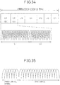
- FIG. 35 is a view showing the gist of the prior art disclosed in Patent Document 2.
- the figure is a view showing the state of allocation of the common control channel and the data channel on the frequency axis.
- the subcarriers dedicated to the transmission of the control signal and the subcarriers dedicated to the transmission of data (data channel) are separately set.
- the common control channel thereof is spread by a unique spread code. Accordingly, when this common control channel is received, it is sufficient to demodulate specific subcarriers, so the amount of signal processing thereof can be reduced.
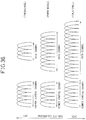
- FIG. 36 is a view showing the gist of the prior art disclosed in Patent Document 3. The figure shows making the frequency band of the data channel in FIG. 35 described above variable in accordance with a propagation distance (communication distance with the base station). Note that the transmission power is changed (large - medium - small).
- the present system is a system for realizing variable speed communication by making the transmission rate per subcarrier fixed and making the number of subcarriers allocated to the user variable.
- the transmission power of each subcarrier is made small and many subcarriers are allocated, while when that distance is long, the transmission power of each subcarrier is made large and a small number of subcarriers are allocated.
- the number of subcarriers used for the common control channel is made small, while a large number of subcarriers are allocated with respect to the data communications use channel (data channel).
- the two are completely separately arranged along the frequency axis.
- the subcarriers dedicated to the common control channel are used to notify the center subcarrier number of the subcarriers allocated for the data channel and the number of used subcarriers from the base station to the mobile station.
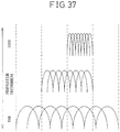
- FIG. 37 is a view showing the gist of the prior art disclosed in Patent Document 4. The figure shows that the bandwidth of each subcarrier is made variable in accordance with whether or not the propagation environment is good.
- the present system changes the bandwidth of each subcarrier while making a total number of subcarriers constant in accordance with the condition of the propagation environment in wireless transmission. For example, when the propagation condition becomes poor, the band of each subcarrier is made wider. Due to this, the transmission can be carried out without changing the total subcarriers, therefore the transmission rate can be maintained constant without regard to the propagation environment.
- Patent Documents 1 to 4 An embodiment of the present invention described herein solves the already explained problems of the prior arts (Patent Documents 1 to 4) explained with reference to FIG. 34 to FIG. 37 explained above. This will be explained in detail below with reference to the drawings.
- FIG. 1 is a view showing the basic configuration of a communications apparatus (transmission side) according to an embodiment of the present invention.
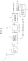
- FIG. 2 is a view showing the basic configuration of a communications apparatus (reception side) according to an embodiment of the present invention.
- reference numeral 10 indicates the communications apparatus (transmission side), and in FIG. 2 , reference numeral 20 indicates the communications apparatus (reception side). These are accommodated in the same communications system (mobile communications system). Note that as already explained, the communications apparatus 10 may be a base station and the communications apparatus 20 may be a terminal, or vice versa. The present invention can be applied to both cases, but for easier understanding, in the following explanation, the communications apparatus 10 on the transmission side will be assumed as the base station, and the communications apparatus 20 on the reception side will be assumed as a terminal unless otherwise indicated.
- the selection function in particular of a used frequency band selecting/setting unit 15 is used to select the used frequency band to be used with the other communications apparatus 20.
- the "used frequency band information" If (frequency) according to this selection is input to a transmission data generation unit 11 where transmission data Dt (transmission) combined integrally with transmission data (user data) Du (user) to be transmitted to the communications apparatus 20 is generated.
- the transmission data Dt includes the transmission data Du and the used frequency band information If, but in actuality further includes also other "communication control information" Ict (control).
- This information Ict is the information concerning a used modulation scheme for example QAM and information etc. concerning a one time transmission data amount of the transmission data Du.
- the above transmission data Dt is modulated in a predetermined way at a modulation unit 12, then input to the next multicarrier transmission sender unit 13.
- This sender unit 13 is supplied with a band set instruction signal Sb (band) instructing processing for transmission at the above selected used frequency band by the setting function of the above used frequency band selecting/setting unit 15.
- Sb band
- the sender unit 13 performs the processing for signal transmission by multicarrier transmission at the frequency band based on this signal Sb.
- a wireless unit 14 converts the frequency conversion of the transmission data signal St from the above sender unit 13 and transmits this from the next antenna AT toward another communications apparatus (terminal) 20.
- the wireless signal from the above antenna AT ( FIG. 1 ) is received at the antenna AT ( FIG. 2 ) and further converted in frequency by a wireless unit 21 to be a received data signal Sr which is then input to a multicarrier transmission receiver unit 22.
- This receiver unit 22 processes the received data signal Sr for signal reception according to the multicarrier transmission, then the next demodulation unit 23 demodulates the signal after the signal reception processing.
- the demodulated received data Dr is decoded at a received data decoding unit 24 and separated to the original transmission data Du and the previously set used frequency band information If explained before. Further, the above communication control information let is also separated from that data Dr. Note that the units to be controlled according to this information let are not directly related to the gist of the present invention, so explanations are omitted.
- the original used frequency band information If obtained by separation from the received data Dr is input to a used frequency band setting unit 25.
- the setting unit 25 receives this information If and reproduces the above band set instruction signal Sb.
- This signal Sb is supplied to the above multicarrier transmission receiver unit 22, then this receiver unit 22 performs processing for signal reception according to the multicarrier transmission by using the frequency band selected on the transmission side. Note that the previously determined frequency band is selected in the initial stage of establishment of the wireless channel.
- the transmission side (10) and the reception side (20) can use the same used frequency band by the above-explained band set instruction signal Sb. Further, based on that signal Sb, that used frequency band can be simultaneously extended, reduced, or changed at both of the transmission side (10) and the reception side (20). Thus, the object of the present invention explained before can be achieved.
- the frequency band usable in the communications system as a whole is divided into a plurality of bands.
- the used frequency band of the communications system as a whole is set as 20 MHz, it is divided into four bands of 5 MHz each.
- One band 5 MHz is used to transmit the information of the control channel for transmitting the used frequency band information and the transmission channel (data channel) for transmitting the transmission data.
- the frequency band for transmitting at least the control channel is defined as the "main band” and a further extended frequency band is defined as an "extension band".
- the bandwidth of each subcarrier is 50 kHz
- the information of the control channel and the data channel are transmitted by using the series of these 100 subcarriers.
- the two information are multiplexed by time division multiplexing.
- Patent Document 3 Japanese Patent Publication (A) No. 2004-214746
- the information of the "main band” is received and decoded to learn the used frequency band (or number of used frequency bands), therefore, the used frequency band can be easily extended, reduced, and changed.
- Patent Document 1 Japanese Patent Publication (A) No. 9-205411
- Patent Document 3 Japanese Patent Publication No. 2004-214746
- the configuration of the reception unit is simplified.
- the extension band described above can be easily changed and added to and even the main band can be changed.
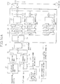
- FIG. 3 is a view showing a concrete example of the communications apparatus (transmission side) 10 that is helpful for understanding the present invention.
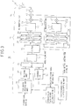
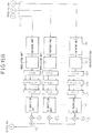
- FIG. 4 is a view showing a concrete example of the communications apparatus (reception side) 20 that is helpful for understanding the present invention. Note that, same components will be indicated by same reference numerals or symbols throughout all of the figures. Further, the concrete examples shown in FIG. 3 and FIG. 4 are applicable to embodiments and background examples described hereinafter.
- the communications apparatus (transmission side) 10 first, the parts corresponding to the components 11 to 15 and Du, Dt, St, and Sb shown in FIG. 1 are shown assigned these reference numerals or symbols 11 to 15 and Du, Dt, St, and Sb.
- the transmission data generation unit 11 is configured by a data block preparation unit 31, an encoding unit 32, a transmission data amount calculation unit 33, an encoding unit 34, and a multiplexing unit (Mux) 35 according to the example of the present figure.
- the transmission data amount calculation unit 33 first calculates a transmission data length, then the data block preparation unit 31 prepares data blocks for each transmission data length. Further, the encoding unit 32 encodes the transmission data by using that transmission data length.
- the above used frequency band information If is encoded together with the communications control information Ict indicating the used modulation scheme etc. at the encoding unit 34. Note that the encoding units 32 and 34 may encode Du and If all together as one encoding unit.
- the encoded outputs from the two encoding units 32 and 34 are multiplexed at the multiplexing unit (Mux) 35 and become the already explained transmission data Dt.
- This data Dt is further modulated at the modulation unit 12 as explained before.
- the method of this multiplexing there are frequency division multiplexing separating subcarriers and using the same, time division multiplexing (by using for example a frame format shown in FIG. 16 ), code division multiplexing etc.
- the modulation scheme by the modulation unit 12 there are QPSK, 16QAM, 64QAM, etc.
- this is configured by components 36, 37, 38, 39, and 40. Note that this is shown as an example based on communications according to OFDM. Another example based on communications according to MC-CDMA is shown in FIG. 7 ( FIG. 8 ).
- the demultiplexing unit (DeMux) 36 demultiplexes this into the information belonging to the "main band” and the information belonging to the "extension bands".
- the information belonging to the "main band” is converted to a parallel signal at a serial/parallel converter (S/P) 37, then a time-frequency transform is applied to the parallel signal at an Inverse Fast Fourier Transform unit (IFFT) 38.
- IFFT Inverse Fast Fourier Transform unit
- the parallel signal transformed into frequency is converted to a serial signal again at a parallel/serial converter (P/S) 39.
- a guard interval (GI) insertion unit 40 inserts a guard interval GI into the serial signal for preventing inter-symbol interference.
- the thus obtained transmission data signal St is input to the wireless unit 14.
- This wireless unit 14 is, according to the example of the present figure, configured by a general mixer 41, a local oscillator 42, and a power amplifier 44 (a D/A converter, a filter, etc. are omitted) and transmits the transmission data signal St from the antenna At.
- an adder unit 43 is provided in the middle.
- the adder unit 43 applies the same processing as the processing for the "main band” by the above-explained components 37, 38, 39, 40, 41, and 42 with respect to the information belonging to the above “extension bands” demultiplexed at the demultiplexing unit (DeMux) 36 as explained before by the components 37', 38', 39', 40', 41', and 42', obtains the transmission data signal St on the "extension band” side, and combines the same together with the already explained transmission data signal St on the "main band” side.
- the transmission data on the "extension band” side described above is generated only when data transmission by the "extension bands” is needed. Whether or not it is needed is determined according to the band set instruction signal Sb from the already explained selecting/setting unit 15.
- the wireless unit 21 eliminates an undesired band of a signal in the signal received from the antenna AT by a band pass filter (BPF) 51, converts the remainder to a predetermined reception frequency by the mixer 52 and the local oscillator 53, and thereby obtains the received data signal Sr.
- BPF band pass filter
- This received data signal Sr is input to the multicarrier transmission receiver unit 22 and processed.
- This receiver unit 22 is, according to the example of the present figure, configured by the components 54, 55, 56, 57, and 58.
- the guard interval (GI) elimination unit 54 eliminates the guard interval inserted at the transmission side.
- the signal after the GI elimination is further converted to a parallel signal at the serial/parallel converter (S/P) 55.
- the Fast Fourier Transform unit (FFT) 56 applies a frequency-time transform to the parallel signal.
- the time transformed parallel signal is converted to a serial signal again at the parallel/serial converter (P/S) 57.
- the mixer 52' and the local oscillator 53' extract the signal of the "extension band” and apply the same processing as the processing by the above-explained components 55 to 57 by the same components S/P 55', FFT 56', and P/S 57' to obtain a time-transformed serial signal.
- the serial signals from the above parallel/serial converters 57 and 57' are multiplexed at the multiplexing unit (Mux) 58 and further demodulated at the demodulation unit 23. Note that when only information belonging to the "main band" is transmitted, the above multiplexing unit 58 does not perform the multiplexing, but only passes the signal therethrough.
- the signal from the multiplexing unit 58 becomes the received data Dr demodulated at the next demodulation unit 23, then is input to the received data decoding unit 24.
- This decoding unit 24 is, according to the example of the present figure, configured by a demultiplexing unit (DeMux) 59, a data channel decoding unit 60, a control channel decoding unit 61, and a transmission data amount calculation unit 62.
- DeMux demultiplexing unit
- the above demultiplexing unit 24 demultiplexes the received data Dr to data channel side data and control channel side data and distributes these to the decoding unit 60 and the decoding unit 61. From the decoding unit 60, the original transmission data Du is reproduced based on the transmission data amount explained later. On the other hand, from the decoding unit 61, the "used frequency band information" If is reproduced.
- the data length of the received transmission data is calculated here based on that If, and the transmission data is decoded by the above decoding unit 60 based on this data length.
- the above information If from the decoding unit 61 is given to the already explained used frequency band setting unit 25 on the other hand, where the above band set instruction signal Sb is generated. Then, according to the content of this signal Sb, the circuit portions (22, 58, 59) are set corresponding to the selected frequency band by the shown dotted line route.
- the received data decoding unit 24 of FIG. 4 may be configured so that the received data Dr is input to one decoding unit (making the decoding units 60 and 61 common) at first and decoded, then demultiplexed to the data channel and the control channel at the demultiplexing unit 59.
- the frequency band of the "main band” is fixed, and only the frequency bands of the "extension bands” are variable.
- not only the “extension bands”, but also the "main band” can be made variable in frequency bands. An example of a configuration accomplishing this is shown in the drawings.
- FIG. 5 is a view showing a modification of the communications apparatus (transmission side) 10
- FIG. 6 is a view showing a modification of a communications control device (reception side) 20.
- FIG. 7 is a view showing another modification of the communications apparatus (transmission side) 10
- FIG. 8 is a view showing another modification of the communications apparatus (reception side) 20.
- the difference resides in the point that a copier unit 46 and a multiplication unit 47 are used. Further, in the receiver unit 22 shown in FIG. 8 , the difference resides in the point that a multiplication unit 65 and a combining unit ( ⁇ ) 66 are used.
- the generated transmission data is modulated and copied by the number of subcarriers at the copier unit 46.
- the multiplication unit 47 multiplies the copied signals by spread codes (C1, C2 ... Cn).
- the IFFT units (38, 38') apply IFFT to the results to apply a time-frequency transform.
- the GI insertion unit 40 inserts a GI, then the signal is converted in frequency and transmitted from the antenna AT. Further, the setting of the multicarrier transmission sender 13 is changed based on the used frequency band selected at the used frequency band selection unit 15.
- the received signal is frequency converted to obtain a base band signal, then the GI is eliminated at the GI elimination unit 54.
- the signal is converted from a serial to parallel format (55, 55'), and each of the parallel signals is multiplied by the spread codes (C1, C2 ... Cn) at the multiplication unit 65 and despread.
- the results thereof are subjected to FFT at the FFT units (56, 56'), a frequency-time transform is carried out, then the results are summed up at the combining unit 66.
- the result of this is demodulated at the demodulation unit 23.
- the same processing as that explained before is carried out to extract the used frequency band information If.
- the setting of the multicarrier transmission receiver unit 22 is changed.
- the number n of codes the frequency spread may be made variable.
- the hardware configuration can be simplified in comparison with the OFDM. Further, on the other hand, there arises a necessity of making the number of point of FFT and IFFT dynamically variable, so the control becomes complex.
- a communications system able to change the used frequency band using OFDM etc. transmits the used frequency band information If by using a specific frequency band. Then, by demodulating and decoding the specific frequency band, the used frequency band If can be obtained. By this information If, the communications in an extension band become possible. This is based on division of the overall frequency band as follows.
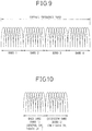
- FIG. 9 is a view showing the pattern of frequency division in a communications system.
- the series of subcarriers of the present figure show the overall frequency band assigned to the communications system.
- This overall frequency band is divided into a plurality of frequency bands.
- the example of division into four is shown, that is, the band is divided into four frequency bands, that is, "BAND 1", “BAND 2", “BAND 3", and "BAND 4". Then, any of these "BAND 1" to "BAND 4" is selected and defined as the above "main band", while another band is selected and defined as an above "extension band".
- FIG. 10 is a view showing the state of selecting one "main band” and one "extension band".
- the above band 1 is selected as the "main band”
- the above band 2 is selected as an "extension band”.
- the "main band” is assigned to the transmission of the control channel (CH) and the data channel (CH), and the "extension band” is assigned to the further transmission of the data channel.
- the main band used by a certain terminal is determined by for example the base station or the higher base station controller. Alternatively, converse to this, the main band may be designated from the terminal side to the base station side.
- the above main band is set at the time of establishment of a wireless channel between communications apparatuses (base station and terminal).
- the setting may be fixed until the communication is completed.
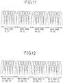
- FIG. 11 is a view showing a first example of a mode of assignment of main bands for a plurality of users
- FIG. 12 is a view showing a second example of a mode of assignment of main bands for a plurality of users. Note that these modes can also be applied to extension bands.
- main bands of users U1 to U4 are individually assigned to a plurality of frequency bands, that is, band 1 to band 4. Note that, in this case, the number of users is restricted by the number of bands.
- the same main band is simultaneously assigned with respect to a plurality of communications apparatuses (user terminals). This becomes possible by user multiplexing.
- this multiplexing method there are time division multiplexing and code division multiplexing or multiplexing combining these.
- the number of used frequency bands (band 1 to band 4) can be changed in accordance with the predetermined transmission rate of the data information (transmission data Du) .
- the base station considers the communication situation, propagation environment, used frequency band, etc. of other terminals in the middle of communications. When judging that another frequency band can be used, it extends the used frequency band. Note that at the time of extension, the available frequency can be extended on a priority basis according to the degree of priority of communications between the terminals, the predetermined transmission rate, and other transmission data attributes (QoS: Quality of Service).
- QoS Quality of Service
- the reception side need only receive that main band first and does not have to receive and demodulate and decode up to the other frequency bands. Further, by using the extension band, a further speed-up of the transmission rate becomes possible, and an improvement of the frequency utilization efficiency can be achieved.
- the transmission characteristic of the control channel must be better in terms of the transmission quality in comparison with the data channel.
- the channel through which the data is to be transmitted must be reliably set.
- the main band including the control channel must select the frequency band having a better propagation environment so that the transmission quality thereof becomes good in comparison with the extension band. Therefore, a concrete example of free selection of the frequency band set as the main band in accordance with quality of the propagation environment will be explained.
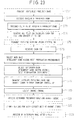
- FIG. 13 is a flow chart showing an example of dynamically changing the frequency band of a main band. Note that the basic transmission/reception operation between the base station and a terminal is as explained in the above Embodiment 1. Further, in FIG. 13 , each solid line block represents an operation of the base station, and each dotted line block represents an operation of the terminal. Note that the reverse may also apply (true for other flow charts explained later as well).
- Step S11 Send pilot channel signal at each frequency band.
- Step S12 Receive all pilot channel signals
- Step S13 Calculate each SNR etc. and convert it to CQI
- Step S14 Transmit each CQI by uplink control channel.
- Step S15 Receive each CQU
- Step S16 Select used frequency band and determine timing of change of band
- Step S17 Transmit the selected used frequency band and determined change timing by downlink control channel.
- Step S18 Receive the above used frequency band and change timing
- Step S19 Change setting for each circuit unit at the above change timing
- Step S20 Start reception operation by using main band after that change.
- the processing for making the main band variable along with the elapse of time according to the above flow chart showing one example in FIG. 13 can be accomplished by for example the following hardware configuration.
- FIGS. 14A and 14B are views showing an example of the hardware configuration of the transmission side of the pilot signal
- FIGS. 15A and 15B are views showing an example of the hardware configuration of the return side of the response (CQI) information to the pilot signal.
- FIGS. 14A and 14B are substantially the same as the configuration of FIG. 3 (or FIG. 5 ) explained before.
- the elements to be newly noted are a pilot signal Sp (or pilot channel) on the left end of FIG. 14A , and a multiplexing unit (Mux) 71 for multiplexing the pilot signal Sp and the used frequency band information If and a CQI extraction unit 72 in FIG. 14B .
- the configuration of this FIG. 14B is substantially the same as the configuration of FIG. 4 (or FIG. 6 ) explained before.
- the component to be newly noted is a CQI extraction unit 72 on the lower side of the center of the present figure. Note that, in FIG. 14B , units corresponding to those in FIG. 4 are given the reference numerals 52, 53, 54, ⁇ used in FIG. 4 plus 100 and thereby indicated as 152, 153, 154, ⁇ .
- FIG. 15A and 15B are the same as the configuration of FIG. 4 (or FIG. 6 ) explained before.
- the components to be newly noted are an SNR measurement unit 75 and a CQI calculation unit 76 in FIG. 15A and further an encoding unit 78 and an adder unit 79 in FIG. 15B after passing through a loop back path 77.
- FIG. 15A parts corresponding to those in FIG. 4 (reception side) are indicated by using the reference numerals 52, 53, 54, ⁇ used in FIG. 4
- FIG. 15B parts corresponding to those in FIG. 3 (transmission side) are given the reference numerals 12, 37, 38, ⁇ used in FIG. 3 plus 100 and thereby indicated as 112, 137, 138, ⁇ .
- the above pilot signal Sp is transmitted after multiplexing with other transmission information in actual operations.
- This multiplexing method includes for example the following two schemes:
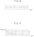
- FIG. 16 is a view showing an example of first multiplexing of a pilot signal
- FIG. 17 is a view showing an example of second multiplexing of a pilot signal. Note that, in both figures, “P” represents the pilot signal Sp, “C” represents the already explained communication control information let, and “D” represents the already explained transmission data Du.
- FIG. 16 shows that the pilot signal Sp is multiplexed along with the elapsed time
- FIG. 17 shows that the pilot signal Sp is multiplexed along with both the elapsed time and the frequency.
- FIG. 18 is a view showing an example of the dynamic change of the main band in the above-explained Background Example 1 for easier understanding. Time elapses from the top toward the bottom in the present figure. Along with the elapse of time, the main band changes as for example "BAND 1" -> "BAND 2" -> “BAND 3" -> "BAND 4" following the better propagation environment.
- the base station multiplexes the signal for measuring the propagation environment (pilot) in all of the frequency bands used and transmits this as the control channel.
- the pilot channel may be provided in place of the pilot signal Sp.
- the terminal receives the pilot channel signals for all frequency bands (band 1 to band 4), measures the reception conditions and propagation environments, for example the SNR and CIR (carrier to interference ratio), calculates the above CQIs from the measurement values, and sequentially or simultaneously transmits the same to the base station for each band by using the uplink control channel. Note that it may also transmit the measurement results of the above CIR and SNR as they are.
- SNR reception conditions and propagation environments
- CIR carrier to interference ratio
- the base station receives the uplink control channel signal and demodulates and decodes the CQIs. It selects the frequency band having the best CQI value from among the plurality of CQIs as the main band. It sends this selection result and the timing of change of the main band on the downlink control channel to the terminal.
- the terminal receives this downlink control channel signal and demodulates and decodes this to extract the information of the used frequency band and timing of change. Then, at the timing of change, it changes the used frequency band.
- the timing of change may be determined according to for example an absolute time or relative time or a slot unit. Further, it is also possible not to transmit the timing of change, but set it as after, e.g., 5 slots from the transmission of the downlink control channel signal etc. and thereby fix it for the system.
- the frequency band having the best propagation environment was selected as the main band, but a case where the best frequency band cannot be selected due to the situation of the other terminal may also be considered. In such case, the second best frequency band next to that may be selected.
- the terminal may similarly select the frequency band having the best propagation environment and transmit this to the base station.
- the SNRs, CIRs, etc. may be measured in the terminal simultaneously for all frequency bands as explained above or in a time division manner. Further, in a situation where bands having narrow frequency band widths continue, the propagation environment will not largely vary, therefore, in such case, only one frequency band need be measured. Further, the measurement value thereof may be made a mean value after measurement over a certain time.
- the extension band was explained by assuming transmission of only the transmission data Du, but to measure the propagation environment of each frequency band, in addition to the transmission data Du, a pilot channel or pilot signal may also be transmitted.
- the transmission characteristic of the control channel must be better than the transmission characteristic of the data channel in transmission quality. Accordingly, for the main band including the control channel, it is necessary to select a frequency band having a good propagation environment. According to the above-explained operation, it becomes possible to select a frequency band under the best propagation environment as the main band. Further, even when the propagation environment changes along with the elapse of time, it becomes possible to always select the frequency band under the best propagation environment as the main band.
- the main band is variably set, therefore unbalance of the utilization situation (load) among frequency bands can be avoided and improvement of the frequency utilization efficiency can be achieved.
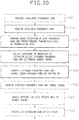
- FIG. 19 is a flow chart showing a first example of the introduction and change of an extension band
- FIG. 20 is a flow chart showing a second example of the introduction and change of an extension band.
- FIG. 21 is a flow chart showing a third example of the introduction and change of an extension band.
- FIG. 19 shows a control flow in a case of selecting an extension band by using the used frequency band of the terminal and the CQI of each frequency band.
- FIG. 20 shows a control flow in a case of selecting an extension band by using the used frequency band thereof, the usage situation of each frequency band, and the predetermined transmission rate of the transmission data.
- FIG. 21 shows a control flow in a case of selecting an extension band by using the used frequency band of the terminal, the CQI of each frequency band, the usage situation of each frequency band, and the predetermined transmission rate of the transmission data.
- Step S21 Transmit available frequency band.
- Step S22 Receive available frequency band
- Step S23 transmit pilot channel signals by using available frequency band.
- Step S24 Receive all pilot channel signals, calculate SNRs etc., and convert it to CQIs, and Step S25: transmit CQIs through uplink control channel.
- Step S26 Receive above CQIs
- Step S27 select existence of need of extension from CQIs, select extended frequency band, and determine timing of change thereof
- Step S28 transmit extended frequency band and timing of change through downlink control channel.
- Step S29 Receive above extended frequency band and timing of change
- Step S30 change setting for each circuit part at the timing of change
- Step S31 start reception operation by using extension band after that change.
- Step S41 transmit available frequency band.
- Step S42 Receive above available frequency band
- Step S43 confirm usage situations of frequency bands and predetermined transmission rate of transmission data Du
- Step S44 select existence of necessity for extension, select extended frequency band, and determine timing of change thereof
- Step S45 transmit extended frequency band and timing of change through downlink control channel.
- Step S46 Receive above extended frequency band and timing of change
- Step S47 change setting for each circuit unit at the timing of change
- Step S48 start reception operation by using extension band after that change.
- Step S51 transmit available frequency band.
- Step S52 Receive available frequency band
- Step S53 transmit pilot channel signals by using available frequency band.
- Step S54 Receive all pilot channel signals, then calculate SNRs etc., convert to CQIs, and Step S55: transmit above CQIs through uplink control channel.
- Step S56 Receive above CQIs
- Step S57 confirm usage situations of frequency bands and predetermined transmission rate of transmission data Du
- Step S58 select existence of necessity for extension, select extended frequency band, and determine timing of change thereof
- Step S45 transmit extended frequency band and timing of change through downlink control channel.
- Step S60 Receive above extended frequency band and timing of change
- Step S61 change setting for each circuit unit at the timing of change
- Step S62 start reception operation by using extension band after that change.
- the frequency band available by a terminal is transmitted from the terminal to the base station (or base station controller). This is the above-explained terminal available frequency band. Note that an explanation will be given by assuming a case where this available frequency band is notified, but it may also be considered not to perform such notification in a case where the available frequency band is previously determined in the communications system.
- the base station transmits pilot signals Sp, and a terminal transmits the above CQIs calculated based on the received pilot signals Sp to the base station.
- the base station considers the available frequency band of the terminal, the CQI of each frequency band transmitted from the terminal, the utilization situation of the other terminals, the predetermined transmission rate of the data Du to be transmitted, and so on and judges if the frequency band must be extended (used frequency band must be changed) for that terminal.
- the frequency band When extending is needed, the frequency band is selected. Further, the above timing of change when extending the used frequency band is selected. Then, the selection information of this extension band and the above timing of change are transmitted by using the control channel.
- the terminal receiving this control channel signal changes the setting of each circuit unit in the terminal based on the information for the extension band and the timing of change, then starts the reception by using that extension band.
- the terminal transmits the frequency band useable by that terminal to the base station or its higher base station controller etc.
- the base station receiving this transmits pilot channel signals or pilot signals Sp by using that used frequency band. Note that when transmitting pilot channel signals using a common channel common to all terminals, the selection of the used frequency band is not needed.
- the terminal receiving the pilot channel signals via the frequency bands calculates the above CQIs based on the above CIRs, SNR, etc., and transmits the CQI calculated values to the base station through the uplink control channel.
- the base station receiving these considers the CQIs, the utilization situations of the frequency bands, the predetermined transmission rate of the transmission data Du, and other QoS, selects the existence of the necessary for extension and the used frequency band in the case where the extension is carried out, determines the timing of change of the band, and notifies the information to the terminal via the downlink control channel.
- the terminal receiving the information sets or re-sets each circuit unit of the terminal at the above timing of change and receives signals by using the extension band after the change at the above timing of change.
- FIG. 22 is a view showing an example of the dynamic change of the extension band in the present background example for easier understanding.
- the elapse of time goes from the top toward the bottom in the present figure.
- the extension band is set as "BAND 2" -> "band 2 + band 3 + band 4" exemplified in the figure whenever there is a necessity of extension while selecting a good frequency band next best to the frequency band having the best propagation environment.
- the expansion band may be set by combining a plurality of bands.
- the frequency band having a relatively good propagation environment can be selected as the extension band for a propagation environment changing along with the elapse of time. Due to this, the transmission error of the control channel information is reduced, the hardware setting of the reception side becomes easier, and the improvement of the transmission quality becomes possible. Further, the number of times of resending the data can be decreased, therefore the transmission rate can be enhanced. Further, if considering the processing time for correcting the settings on the reception side and notifying the change of the extension band to the other party in advance, the change of setting described above with respect to the apparatus becomes easier.
- FIG. 23 is a flow chart showing an example of changing both of the main band and an extension band.
- Step S71 Transmit available frequency band.
- Step S72 Receive available frequency band
- Step S73 transmit pilot channel signals using that available frequency band.
- Step S74 Receive all pilot channel signals, calculate SNRs etc., and convert to CQIs, and Step S75: transmit above CQIs through uplink control channel.
- Step S76 Receive above CQIs
- Step S77 receive main band, that is, frequency band having best propagation environment
- Step S78 further, select extension band, that is, frequency band having second best propagation environment
- Step S79 transmit extended frequency band and its timing of change through downlink control channel
- Step S80 select timing of change thereof.
- Step S81 Receive above extended frequency band and timing of change
- Step S82 change setting for each circuit unit at the timing of change
- Step S83 start reception operation in extension band after that change.
- each main band and each extension band are selected based on a predetermined transmission rate of the transmission data Du (see FIG. 24 ).
- the frequency band having the best propagation environment is selected as the main band based on the above CQIs of the frequency bands transmitted from the terminal.
- the frequency band having the propagation improvement which next best to that (second) is selected as the extension band.
- the timing of change is selected, and these are transmitted to the other party via the control channel.
- the terminal receiving the used frequency band information (both of the main band and the extension band) and the change timing information changes the settings of the reception side circuit unit at this timing of change, then receives the two signals of the main band and the extension band.
- FIG. 24 is a flow chart showing an example of the dynamic change of the main band and extension band in the present example for easier understanding.
- the elapse of time goes from the top toward the bottom in the figure.
- the main band is set as "BAND 1" -> "BAND 1" -> "BAND 3" -> "BAND 2" as exemplified in the present figure
- the extension band is set while forming a pair at either the left or right of the main band (on left side or right side in the present figure). Note, the two bands do not always have to form a pair.
- this extension band (band 4) does not exist, and when looking at for example the fourth stage in the figure, this extension band may not exist in the shown band 3, but may exist in the band 4 on the right adjacent to that with a space.
- the transmission error of the control channel information is reduced, the hardware settings on the reception side become easier, and improvement of the transmission quality becomes possible. Further, the number of times of resending the data can be decreased, therefore the transmission rate can be improved. Further, by considering the processing time for correcting the settings on the reception side and notifying the change of the main band and the extension band to the other party in advance, the change of the hardware settings becomes easy.
- FIGS. 15A and 15B can be used or the example of configuration of FIG. 25 can be used.
- FIG. 25 is a view showing an example of the hardware configuration on the return side of the response (CQI) information to the pilot signals.
- the example of configuration of the present figure is similar to the example of configuration of FIGS. 15A and 15B described above. The difference thereof resides in that individual processing linked with each of a plurality of frequency bands is carried out in FIG. 15B , but in the lower half in FIG. 25 , CQIs for a plurality of frequency bands are multiplexed and processed all together. That is, in FIG. 25 , the transmission quality (CQI) is transmitted to the other party by one control channel.
- a multiplexing unit (Mux) 80 is introduced into the output side of the loop back path 77.
- the CQIs of the different frequency bands when transmitting the CQIs of the different frequency bands from a terminal to the base station, they may be transmitted through the uplink control channel for each frequency band or the CQIs for all frequency bands may be transmitted through the uplink control channel of for example the main band.
- FIGS. 15A and 15B When transmitting the CQIs by using the uplink control channel for each frequency band, the example of configuration of FIGS. 15A and 15B is used. Note that, in the present example of configuration, no description is made of the uplink transmission data Du, but it is also possible to multiplex this data Du on the control channel and transmit the same. Further, the present example of configuration assumes a case where pilot channel signals are simultaneously received for a plurality of frequency bands.
- the signal of each frequency band is received and converted in frequency corresponding to that frequency band. Thereafter, the GI is eliminated at the GI elimination unit 54, a frequency-time transform is applied by the S/P unit 55, FFT unit 56, and P/S unit 57, then the result is demodulated at the demodulation unit 23. The propagation situation is measured by the SNR, CIR, etc. using this demodulation signal, then the CQI value is calculated.
- the above CQI value calculated for each frequency band is transmitted through the control channel of each frequency band. At this time, it is also possible to transmit the other control channel signal together. Further, it is also possible to transmit the same together with the uplink transmission data.
- the calculated CQI enters into the part of FIG. 15B by the loop back path 77, is encoded at the encoding unit 78, modulated at a modulation unit 112, then subjected to a time-frequency transform at an S/P unit 137, an IFFT unit 138, and a P/S unit 139. Further, the GI is inserted at a GI insertion unit 140, then the result is converted to the corresponding frequency band and transmitted from the antenna AT.
- the example of configuration of FIG. 25 described above is employed for a case of transmitting all CQIs by using the uplink control channel of a specific frequency band.
- the CQI in each frequency band is calculated.
- These calculation results are combined into one at the above multiplexing unit (Mux) 80, then this is encoded at the encoding unit 78. Further, it is modulated at the modulation unit 112, then subjected to a time-frequency transform at the S/P unit 137, IFFT unit 138, and P/S unit 139 and given a GI at the GI insertion unit 140. Thereafter, the result is converted in frequency by the circuits 141 and 142 and transmitted from the antenna AT.
- Mux multiplexing unit
- the frequency band used for the transmission of the CQI to be used the main band which is selected because of its relatively good transmission environment may be selected, the frequency band having the best propagation environment (best CQI) may be selected, and another frequency band may be selected. Further, the frequency band previously set as the communications system may be used.
- the characteristic feature disclosed in the present background example is that, for each of a plurality of frequency bands (band 1 to band 4), at least one of information (i to iv) of (i) a frequency band identification number, (ii) used/not yet used as main band, (iii) used/not yet used as extension band, and (iv) current status maintained is encoded and transmitted to the communications apparatus of the other party.
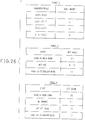
- FIG. 26 is a view showing tables for explaining the high efficiency transmission of the used frequency band information.
- Table 1 shows an example of correspondence of the used frequency band and band number
- Table 2 and Table 3 show a first example and a second example of the method of setting of used/not yet used of the used frequency band.
- the amount of control channel information can be reduced in comparison with the case where the value of frequency per se is transmitted.
- Table 1 A concrete example will be explained by using the above Table 1 to Table 3. Note that, here, an example where the frequency band useable by the communications system as a whole is set to 800 MHz to 820 MHz and this is divided into four frequency bands as in FIG. 9 for use is shown.
- band numbers (1, 2, 3, 4) are assigned to the bands as shown in Table 1. Further, which frequency band is to be used as the main band, and which frequency band is to be used (or not used) as the extension band is set as in Table 2.
- control data was prepared in a sequence of band 1, band 2, band 3, and band 4, but this sequence may be any so far as recognition is possible on the transmission side and the reception side. Further, the number of bands can be freely increased or decreased. Further, an explanation was given here by taking as an example four consecutive frequency bands, but nonconsecutive frequency bands having not yet used bands in the middle may also be employed.
- the amount of information can be reduced in comparison with for example the case where the value of the center frequency of the band per is transmitted.
- the data length of the control signal can be compressed. Accordingly, the ratio of the transmission data and the control channel information is reduced for the latter, and accordingly the transmission efficiency of the transmission data is improved.
- FIG. 27 is a view showing an example of dynamic change of the extension band.
- FIG. 27 shows a case nonconsecutive extension bands (see the fourth stage of the same diagram) are selected. Note that the method of viewing FIG. 27 is exactly the same as the method of viewing the above FIG. 22 . This will be concretely explained below.
- FIG. 22 shows a case where the extension bands are consecutively selected. Note as one example, a case where a consecutive band forming a pair with the main band is selected as the extension band. In the mode of this FIG. 22 , the extension band is consecutive with the main band, therefore, in comparison with the case of nonconsecutive bands ( FIG. 27 ), the signal processing becomes simpler. Note that the transmission operation and the reception operation are the same as those explained in the above embodiments.
- FIG. 27 also shows a case where an extension band is nonconsecutive (fourth stage). In this way, it is also possible to nonconsecutively select an extension band with respect to the main band or an adjacent extension band from the used frequency band of the terminal, the propagation environment, and the balance with other terminals.
- a subcarrier bridging the consecutive frequency bands (see a dotted line SC of FIG. 22 ) is not set in the explanation hitherto, but according to the usage situation of the other terminals, it is also possible to set a subcarrier bridging two frequency bands and increase the amount of transmission information by that amount.
- the reception side terminal does not receive signals at the above nonconsecutive frequency bands or forcibly processes the related signals as meaningless signals. Due to this, even when the extension bands are non consecutive, reception can be carried out without problem.
- the characteristic feature disclosed in the present background example resides in that the bandwidth of each of a plurality of frequency bands (band 1 to band 4) is set to a predetermined constant value and the number of the series of subcarriers in each band is made a predetermined constant value.
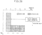
- FIG. 28 is a view showing a first example of a band extension pattern
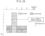
- FIG. 29 is a view showing a second example of a band extension pattern
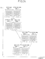
- FIG. 30 is a view showing a third example of a band extension pattern.
- FIG. 28 to FIG. 30 is substantially the same as the method of viewing the above FIG. 22 , FIG. 24 , FIG. 27 , etc. While FIG. 22 , FIG. 24 , FIG. 27 , etc. show patterns using actual waveforms, FIG. 28 to FIG. 30 only show patterns as blocks of subcarriers in place of such actual waveforms. This is for facilitating the explanation of the present Embodiment 8. Namely, they show the concept of a "frequency band unit" visually for easier understanding. Note that terms described in FIG. 28 to FIG. 30 are already explained except a "processing delay". This processing delay, when viewing for example FIG. 4 , means a time delay required for the processing from when the used frequency band information If is input to the used frequency band setting unit 25 to when the band set instruction signal Sb is generated and further the parameters finish being set in each circuit part.
- This processing delay when viewing for example FIG. 4 , means a time delay required for the processing from when the used frequency band information If is input to the used frequency band setting unit 25 to when the band set
- the used frequency band of the communications system as a whole is divided into a plurality of bands (band 1 to band 4), the "number of subcarriers is made constant" in the divided frequency bands, and transmission between communications apparatuses is carried out by using one or more of the frequency bands. Due to this, an improvement of the efficiency of frequency utilization can be achieved.
- one frequency band is set to 5 MHz, and the number of subcarriers in that frequency band is set to 25.
- the above used frequency band is made variable in units of frequency bands.
- FIG. 28 to FIG. 30 show concrete examples of band extension in units of bands.
- An abscissa in each diagram indicates the bandwidth, one hatched block represents one frequency band, and a plurality of subcarriers are assumed to be contained in that one frequency band.
- FIG. 9 it may be considered that the band 1, band 2, band 3, and band 4 are arranged from the left.
- FIG. 28 shows a case where the band 1 is used as the main band
- FIG. 29 shows a case where the band 2 is used as the main band
- FIG. 30 shows an example of changing the setting of the extension band along with the elapse of time and shows a case where those extension bands include a nonconsecutive one (see the sixth stage). Note that the concrete operation of transmission/reception is as explained in the above embodiments.
- the used frequency band can be easily made variable, and it becomes possible to raise the utilization efficiency of the frequency. Further, when compared with the case where the used frequency band is made variable in units of subcarriers, the above transmission/reception operation becomes further simpler, and the configuration of a transmitter/receiver becomes simpler.
- FIG. 31 is a view showing an example of the configuration of the communications apparatus (transmission side) according to the present background example
- FIG. 32 is a flow chart showing an example of the operation in the apparatus of FIG. 31 .
- the figure is substantially the same as the configuration of the above FIG. 5 (also FIG. 3 is the same), but differs in the point that a frequency band selecting/setting unit 85 (modification of 15) and an actual transmission rate calculation unit 86 shown on the left end in the figure are introduced.
- Step S91 Confirm predetermined transmission rate
- Step S92 confirm amount of transmission data
- Step S93 calculate actual transmission rate.
- Step S994 Judge whether or not it is necessary to extend used frequency band based on rate values in steps S91 and S93 and judge that it is necessary.
- Step S95 Select extended frequency band and determine timing of change
- Step S96 transmit that extended frequency band and its timing of change through downlink control channel.
- Step S97 Receive extended frequency band and timing of change
- Step S98 change setting of each circuit unit at that timing of change
- Step S99 start reception by using extension band after change.
- a predetermined transmission rate Rd of a certain transmission data Du is 10 Mbps
- the transmission is carried out by using the main band and the extension band.
- an actual transmission rate Ra can be calculated by an actual transmission rate calculation unit 86 of FIG. 31 .
- This actual transmission rate Ra and the predetermined transmission rate Rd are compared at the above selecting/setting unit 85.
- the actual transmission rate Ra is lower, the used frequency band is increased (extended).
- the predetermined transmission rate Rd can be secured even when the actual transmission rate Ra is much higher than the predetermined transmission rate Rd and the used frequency band is decreased, the used frequency band is decreased (reduced).
- an improvement of the efficiency of frequency utilization can be achieved while satisfying the predetermined transmission rate.
- FIG. 33 is a view for explaining the present background example.
- the parts to be particularly noted are a “restricted band” and a “overall frequency band after lifting restriction”.
- the characteristic features disclosed in the present example are as described below:
- the above limited used frequency band (“limited band a") is operated by dividing the band (a) into one or more frequency bands in the same way as the above embodiment and background examples. Then, at this time, the restricted frequency bands (band b, band c, and band d) are individually divided to one or more frequency bands as well. Note that preferably the used frequency band (band a) and restricted frequency bands (bands b to d) are divided with the same bandwidth. FIG. 33 assumes division with the same bandwidth in this way. Further, in FIG. 33 , the used frequency band is limited to the "band a" which is operated as a single frequency band. The whole restricted frequency band is divided into three bands (band b to band d), but these bands b to d can not be used at present due to the restrictions. Note that the number of subcarriers and the subcarrier bandwidth of each of these bands are constant.
- the frequency band is set as a single band (band a), therefore the used frequency band cannot be extended.
- the number of used frequency bands becomes four (bands a to d), and the operation can be immediately shift to the operation of the embodiment and background examples explained before.
- the used frequency band is limited at present, but when the restriction is lifted after that, the operation can be immediately shifted to the system operation described herein. This enables the flexible operation of the communications system.
Landscapes
- Engineering & Computer Science (AREA)
- Signal Processing (AREA)
- Computer Networks & Wireless Communication (AREA)
- Computer Security & Cryptography (AREA)
- Quality & Reliability (AREA)
- Mobile Radio Communication Systems (AREA)
- Small-Scale Networks (AREA)
Claims (4)
- Station de base comprise dans un système de communication pour un échange de données entre une station de base (10) et des stations mobiles (20) par multiplexage par répartition dans le temps en utilisant une pluralité de bandes de fréquence, la station de base comprenant :une unité de définition (15) configurée pour définir une bande de fréquence spécifique pour chaque station mobile (20) indépendamment parmi une pluralité de bandes de fréquence affectées au système de communication lorsqu'un canal sans fil entre la station de base et la station mobile est établi, et configurée pour définir une ou plusieurs bandes de fréquence dédiées pour chaque station mobile (20) indépendamment des bandes de fréquence, et dans laquellela bande de fréquence dédiée est destinée à être utilisée pour une transmission de données dédiées à chaque station mobile indépendamment et est spécifiée par des informations de bande de fréquence dédiée, etune unité de génération de données de transmission (11) configurée pour générer des données dédiées et des informations de bande de fréquence dédiée pour chaque station mobile indépendamment ; etune unité de transmission (13) configurée pour transmettre les données dédiées et les informations de bande de fréquence dédiée à la station mobile (20) indépendamment, en utilisant la bande de fréquence spécifique.
- Station mobile comprise dans un système de communication pour un échange de données entre une station de base (10) et des stations mobiles (20) par multiplexage par répartition dans le temps en utilisant une pluralité de bandes de fréquence, la station mobile comprenant :une unité de réception (22) configurée pour recevoir des informations de bande de fréquence dédiée via une bande de fréquence spécifique ; et dans laquellela bande de fréquence spécifique est définie pour chaque station mobile (2) indépendamment parmi une pluralité de bandes de fréquence affectées au système de communication lorsqu'un canal sans fil entre la station de base et la station mobile est établi, etune unité de définition (25) configurée pour définir la bande de fréquence spécifique en vue de recevoir des données dédiées et des informations de bande de fréquence dédiée et une ou plusieurs bandes de fréquence dédiées en vue de recevoir des données dédiées, dans laquellelesdites une ou plusieurs bandes de fréquence dédiées sont définies parmi la pluralité de bandes de fréquence autres que la bande de fréquence spécifique.
- Procédé d'échange de données par une station de base comprise dans un système de communication entre la station de base (10) et des stations mobiles (20) par multiplexage par répartition dans le temps utilisant une pluralité de bandes de fréquence, le procédé comprenant :définir une bande de fréquence spécifique pour chaque station mobile (20) indépendamment parmi une pluralité de bandes de fréquence affectées au système de communication lorsqu'un canal sans fil entre la station de base et la station mobile est établi, etdéfinir indépendamment une ou plusieurs bandes de fréquence dédiées pour chaque station mobile, et dans lequella bande de fréquence dédiée est destinée à être utilisée pour la transmission de données dédiées à chaque station mobile indépendamment et est spécifiée par des informations de bande dédiée, etgénérer des données dédiées et des informations de bande de fréquence dédiée pour chaque station mobile ; ettransmettre les données dédiées et les informations de bande de fréquence dédiée à la station mobile (20), en utilisant la bande de fréquence spécifique.
- Procédé d'échange de données par une station mobile comprise dans un système de communication entre la station de base (10) et des stations mobiles (20) par multiplexage par répartition dans le temps utilisant une pluralité de bandes de fréquence, le procédé comprenant :recevoir des informations de bande de fréquence dédiée via une bande de fréquence spécifique lorsqu'un canal sans fil entre la station de base et la station mobile est établi ; etdéfinir la bande de fréquence spécifique en vue de recevoir des données dédiées et des informations de bande de fréquence dédiée et une ou plusieurs bandes de fréquence dédiées en vue de recevoir des données dédiées, dans lequella bande de fréquence spécifique est définie pour chaque station mobile (20) indépendamment parmi une pluralité de bandes de fréquence affectées au système de communication lorsqu'un canal sans fil entre la station de base et la station mobile est établi, etla ou lesdites bandes de fréquence dédiées sont définies parmi la pluralité de bandes de fréquence autres que la bande de fréquence spécifique.
Priority Applications (1)
| Application Number | Priority Date | Filing Date | Title |
|---|---|---|---|
| EP13187064.4A EP2683107B1 (fr) | 2004-10-29 | 2004-10-29 | Appareil de communication et procédé de communication utilisant un mode de transmission à porteuses multiples |
Applications Claiming Priority (3)
| Application Number | Priority Date | Filing Date | Title |
|---|---|---|---|
| EP04793255.3A EP1816666B1 (fr) | 2004-10-29 | 2004-10-29 | Dispositif de communication par la méthode de transmission par multiporteuse et système de communication |
| PCT/JP2004/016154 WO2006046307A1 (fr) | 2004-10-29 | 2004-10-29 | Dispositif de communication par la méthode de transmission par multiporteuse et système de communication |
| EP13187064.4A EP2683107B1 (fr) | 2004-10-29 | 2004-10-29 | Appareil de communication et procédé de communication utilisant un mode de transmission à porteuses multiples |
Related Parent Applications (3)
| Application Number | Title | Priority Date | Filing Date |
|---|---|---|---|
| EP04793255.3 Division | 2004-10-29 | ||
| EP04793255.3A Division EP1816666B1 (fr) | 2004-10-29 | 2004-10-29 | Dispositif de communication par la méthode de transmission par multiporteuse et système de communication |
| EP04793255.3A Division-Into EP1816666B1 (fr) | 2004-10-29 | 2004-10-29 | Dispositif de communication par la méthode de transmission par multiporteuse et système de communication |
Publications (2)
| Publication Number | Publication Date |
|---|---|
| EP2683107A1 EP2683107A1 (fr) | 2014-01-08 |
| EP2683107B1 true EP2683107B1 (fr) | 2018-03-14 |
Family
ID=36227559
Family Applications (4)
| Application Number | Title | Priority Date | Filing Date |
|---|---|---|---|
| EP13187065.1A Active EP2683108B1 (fr) | 2004-10-29 | 2004-10-29 | Appareil de communication et système de communication utilisant un mode de transmission à porteuses multiples |
| EP13187063.6A Ceased EP2683106B1 (fr) | 2004-10-29 | 2004-10-29 | Appareil de communication et système de communication utilisant un mode de transmission à porteuses multiples |
| EP04793255.3A Active EP1816666B1 (fr) | 2004-10-29 | 2004-10-29 | Dispositif de communication par la méthode de transmission par multiporteuse et système de communication |
| EP13187064.4A Active EP2683107B1 (fr) | 2004-10-29 | 2004-10-29 | Appareil de communication et procédé de communication utilisant un mode de transmission à porteuses multiples |
Family Applications Before (3)
| Application Number | Title | Priority Date | Filing Date |
|---|---|---|---|
| EP13187065.1A Active EP2683108B1 (fr) | 2004-10-29 | 2004-10-29 | Appareil de communication et système de communication utilisant un mode de transmission à porteuses multiples |
| EP13187063.6A Ceased EP2683106B1 (fr) | 2004-10-29 | 2004-10-29 | Appareil de communication et système de communication utilisant un mode de transmission à porteuses multiples |
| EP04793255.3A Active EP1816666B1 (fr) | 2004-10-29 | 2004-10-29 | Dispositif de communication par la méthode de transmission par multiporteuse et système de communication |
Country Status (6)
| Country | Link |
|---|---|
| US (15) | US7953167B2 (fr) |
| EP (4) | EP2683108B1 (fr) |
| JP (1) | JP4515460B2 (fr) |
| KR (2) | KR101008736B1 (fr) |
| CN (1) | CN101053053B (fr) |
| WO (1) | WO2006046307A1 (fr) |
Families Citing this family (76)
| Publication number | Priority date | Publication date | Assignee | Title |
|---|---|---|---|---|
| KR101008736B1 (ko) | 2004-10-29 | 2011-01-14 | 후지쯔 가부시끼가이샤 | 멀티캐리어 전송 방식에 의한 통신 장치, 통신 시스템, 및 통신 방법 |
| CN102098261B (zh) * | 2004-10-29 | 2016-04-20 | 富士通株式会社 | 基于多载波传输方式的通信装置及通信系统 |
| WO2007020994A1 (fr) | 2005-08-19 | 2007-02-22 | Matsushita Electric Industrial Co., Ltd. | Système de communication multiporteuse, appareil de communication multiporteuse et méthode de rapport cqi |
| KR20080044285A (ko) * | 2005-09-16 | 2008-05-20 | 코닌클리케 필립스 일렉트로닉스 엔.브이. | 동적 스펙트럼 접근 무선 시스템에서의 스펙트럼 관리 |
| US8054894B2 (en) * | 2005-10-31 | 2011-11-08 | Motorola Mobility, Inc. | Method and apparatus for providing channel quality feedback in an orthogonal frequency division multiplexing communication system |
| US8594207B2 (en) * | 2005-10-31 | 2013-11-26 | Motorola Mobility Llc | Method and apparatus for providing channel quality feedback in an orthogonal frequency division multiplexing communication system |
| JP4659154B2 (ja) * | 2006-01-18 | 2011-03-30 | 株式会社日立国際電気 | 通信装置 |
| EP2020823B1 (fr) | 2006-05-23 | 2017-04-19 | Sharp Kabushiki Kaisha | Méthode de communication mobile, dispositif de station mobile, dispositif de station de base et système de communication mobile |
| KR101330633B1 (ko) * | 2006-06-08 | 2013-11-18 | 삼성전자주식회사 | 무선 통신 방법 및 장치 |
| EP1881662A1 (fr) * | 2006-07-18 | 2008-01-23 | Siemens Aktiengesellschaft | Réglage des filtres en fonction de l'occupation des bandes voisines |
| KR20110089187A (ko) | 2006-07-28 | 2011-08-04 | 콸콤 인코포레이티드 | 플래시 타입 시그널링을 위한 데이타 인코딩 방법 및 장치 |
| US8477593B2 (en) * | 2006-07-28 | 2013-07-02 | Qualcomm Incorporated | Method and apparatus for sending signaling for data transmission in a wireless communication system |
| JP4519817B2 (ja) * | 2006-08-22 | 2010-08-04 | 株式会社エヌ・ティ・ティ・ドコモ | 基地局および移動局 |
| CN101137135B (zh) | 2006-09-01 | 2011-06-29 | 电信科学技术研究院 | 一种基站及其发送控制调度信息的方法 |
| KR101298641B1 (ko) * | 2006-11-10 | 2013-08-21 | 삼성전자주식회사 | Ofdm 통신 장치 및 방법 |
| KR100826913B1 (ko) | 2006-12-07 | 2008-05-06 | 한국전자통신연구원 | 이동 통신 시스템의 주파수 할당 방법 |
| KR100891467B1 (ko) | 2007-02-12 | 2009-04-02 | (주)하모닉스 | 주파수 이동 통신 장치, 및 방법 |
| KR100996085B1 (ko) * | 2007-02-26 | 2010-11-22 | 삼성전자주식회사 | 통신시스템에서 자원 할당 정보 송수신 방법 및 장치 |
| US9344897B2 (en) * | 2007-03-13 | 2016-05-17 | Qualcomm Incorporated | Estimating timing and frequency information for multiple channel wireless communication systems |
| US8831116B2 (en) * | 2007-03-20 | 2014-09-09 | Motorola Mobility Llc | Method and apparatus for providing channel quality and precoding metric feedback in an orthogonal frequency division multiplexing communication system |
| US8503375B2 (en) | 2007-08-13 | 2013-08-06 | Qualcomm Incorporated | Coding and multiplexing of control information in a wireless communication system |
| JP5128234B2 (ja) * | 2007-10-25 | 2013-01-23 | パナソニック株式会社 | 通信装置、及び通信システム |
| CN101426207B (zh) * | 2007-10-29 | 2011-11-16 | 中国移动通信集团公司 | 一种单频网络控制方法及单频网络控制实体 |
| TR201910415T4 (tr) * | 2007-11-06 | 2019-08-21 | Unwired Planet International Ltd | Bir mobil telekomünikasyon sistemindeki yöntemler ve düzenlemeler. |
| JP5121575B2 (ja) * | 2007-12-25 | 2013-01-16 | 京セラ株式会社 | 基地局およびスケジューリング方法 |
| KR101507839B1 (ko) | 2008-03-14 | 2015-04-03 | 엘지전자 주식회사 | 무선접속 시스템에서 채널할당방법 |
| US8594576B2 (en) * | 2008-03-28 | 2013-11-26 | Qualcomm Incorporated | Short-term interference mitigation in an asynchronous wireless network |
| US9668265B2 (en) | 2008-03-28 | 2017-05-30 | Qualcomm Inc. | Technique for mitigating interference in a celllar wireless communication netwok |
| ES2556975T3 (es) * | 2008-05-16 | 2016-01-21 | Telefonaktiebolaget Lm Ericsson (Publ) | Método para un receptor de espectro agregado de radio único, programa informático, receptor y terminal |
| US8761824B2 (en) * | 2008-06-27 | 2014-06-24 | Qualcomm Incorporated | Multi-carrier operation in a wireless communication network |
| EP2308183A4 (fr) * | 2008-07-30 | 2014-07-23 | Lg Electronics Inc | Procédé et dispositif de réception de données dans un système de communications sans fil |
| JP5168015B2 (ja) * | 2008-07-31 | 2013-03-21 | 富士通モバイルコミュニケーションズ株式会社 | 無線基地局装置および移動無線端末装置 |
| EP2312896B1 (fr) | 2008-08-06 | 2018-01-10 | Sharp Kabushiki Kaisha | Dispositif de station de base, dispositif de station mobile et procédés de communication correspondants utilisant une aggrégation de porteuses |
| KR101682034B1 (ko) | 2008-08-18 | 2016-12-05 | 삼성전자주식회사 | 다중 밴드를 사용하는 광대역 무선통신 시스템에서 서브밴드의 선택적 사용을 위한 장치 및 방법 |
| EP2341730B1 (fr) | 2008-09-22 | 2017-11-29 | Sharp Kabushiki Kaisha | Mesures par un terminal utilisant l'aggrégation de porteuses |
| US8514793B2 (en) | 2008-10-31 | 2013-08-20 | Interdigital Patent Holdings, Inc. | Method and apparatus for monitoring and processing component carriers |
| EP2340639A4 (fr) * | 2008-10-31 | 2016-06-08 | Unwired Planet Internat Ltd | Procédé et agencement dans un système de réseau de communications à porteuses multiples |
| KR101160347B1 (ko) | 2008-12-22 | 2012-06-28 | 한국전자통신연구원 | 광대역 무선접속 시스템에서 방송서비스 제공 시스템 및 그방법 |
| US8705424B2 (en) * | 2009-03-30 | 2014-04-22 | Blackberry Limited | User equipment component carrier allocation |
| KR101709501B1 (ko) * | 2009-04-09 | 2017-03-08 | 엘지전자 주식회사 | 다중반송파 지원 광대역 무선 통신 시스템에서의 반송파 관리 절차 수행 방법 및 장치 |
| EP2437560B1 (fr) * | 2009-05-25 | 2016-01-27 | Sharp Kabushiki Kaisha | Système de communication sans fil, procédé de communication sans fil, appareil terminal et appareil de communication |
| BRPI1011352B1 (pt) * | 2009-06-19 | 2020-12-22 | Mitsubishi Electric Corporation | sistema de comunicação móvel |
| JP2011041229A (ja) * | 2009-08-18 | 2011-02-24 | Sony Corp | 送信装置、受信装置、無線装置および送信装置における伝送モード制御方法 |
| WO2011027400A1 (fr) | 2009-09-04 | 2011-03-10 | 株式会社 東芝 | Système de communication |
| US8996007B2 (en) * | 2009-09-11 | 2015-03-31 | Lg Electronics Inc. | Method and apparatus for reassigning frequency resource in a femto base station during handover |
| KR101350002B1 (ko) * | 2009-10-02 | 2014-01-13 | 후지쯔 가부시끼가이샤 | 무선 통신 시스템, 기지국 장치, 단말 장치 및 무선 통신 시스템에서의 무선 통신 방법 |
| JP4740365B2 (ja) | 2009-10-26 | 2011-08-03 | シャープ株式会社 | 移動局装置、基地局装置、無線通信システム、通信制御方法、通信制御プログラム、及びプロセッサ |
| US9584290B2 (en) * | 2009-12-08 | 2017-02-28 | Qualcomm Incorporated | Multiple carrier activation/deactivation in wireless communications |
| JP5446823B2 (ja) * | 2009-12-16 | 2014-03-19 | ソニー株式会社 | ハンドオーバのための方法、端末装置、基地局及び無線通信システム |
| JP5094896B2 (ja) | 2010-02-26 | 2012-12-12 | シャープ株式会社 | 移動局装置、基地局装置、通信制御方法及び集積回路 |
| JP5423499B2 (ja) * | 2010-03-16 | 2014-02-19 | 富士通株式会社 | 基地局装置、通信システムおよび通信システムの制御方法 |
| JP5491268B2 (ja) * | 2010-04-28 | 2014-05-14 | キヤノン株式会社 | 通信装置、その制御方法及びプログラム |
| US9172513B2 (en) | 2010-10-11 | 2015-10-27 | Qualcomm Incorporated | Resource assignments for uplink control channel |
| US20120182895A1 (en) * | 2011-01-13 | 2012-07-19 | Electronics And Telecommunications Research Institute | Apparatus and method for transmitting and receiving channel state information |
| TWI550139B (zh) | 2011-04-04 | 2016-09-21 | 諾菲勒斯系統公司 | 用於裁整均勻輪廓之電鍍裝置 |
| JP5713844B2 (ja) * | 2011-08-25 | 2015-05-07 | 株式会社東芝 | 無線通信装置及び干渉回避方法 |
| US10123327B2 (en) * | 2011-09-19 | 2018-11-06 | Telefonaktiebolaget Lm Ericsson (Publ) | Method and apparatus for transmitting and receiving data in orthogonal frequency division multiplexing system |
| US9516531B2 (en) | 2011-11-07 | 2016-12-06 | Qualcomm Incorporated | Assistance information for flexible bandwidth carrier mobility methods, systems, and devices |
| US9848339B2 (en) | 2011-11-07 | 2017-12-19 | Qualcomm Incorporated | Voice service solutions for flexible bandwidth systems |
| US20130114571A1 (en) * | 2011-11-07 | 2013-05-09 | Qualcomm Incorporated | Coordinated forward link blanking and power boosting for flexible bandwidth systems |
| US9319253B2 (en) * | 2011-11-17 | 2016-04-19 | University Of South Florida (A Florida Non-Profit Corporation) | Edge windowing of OFDM based systems |
| CN104054282B (zh) * | 2012-01-18 | 2018-02-09 | Lg电子株式会社 | 装置对装置通信方法及其装置 |
| JP2013214831A (ja) * | 2012-03-30 | 2013-10-17 | Fujitsu Ltd | 基地局装置、移動局装置、無線送信方法及び無線受信方法 |
| JP6132518B2 (ja) * | 2012-11-21 | 2017-05-24 | オリンパス株式会社 | マルチキャスト送信端末、マルチキャストシステム、プログラムおよびマルチキャスト送信方法 |
| JP5623595B2 (ja) * | 2013-05-31 | 2014-11-12 | シャープ株式会社 | 移動局装置、プロセッサ、無線通信システム、通信制御方法、通信制御プログラム、及び基地局装置 |
| CN103596278A (zh) * | 2013-11-26 | 2014-02-19 | 中国联合网络通信集团有限公司 | 一种数据传输的方法、装置及系统 |
| FR3016103B1 (fr) * | 2013-12-31 | 2017-03-10 | Thales Sa | Procede et systeme de partage du spectre radio |
| US9572106B2 (en) | 2014-10-31 | 2017-02-14 | Qualcomm Incorporated | Dynamic bandwidth switching for reducing power consumption in wireless communication devices |
| WO2016174904A1 (fr) * | 2015-04-30 | 2016-11-03 | ソニー株式会社 | Dispositif de communication, et procédé de communication |
| EP3297351B1 (fr) | 2015-05-13 | 2023-09-20 | Fujitsu Limited | Système de communication radio, station de base, terminal de communication, et procédé de commande de système de communication radio |
| WO2017002251A1 (fr) | 2015-07-01 | 2017-01-05 | 富士通株式会社 | Système de communication sans fil, terminal de communication, station de base et procédé de commande de cellule |
| WO2017005295A1 (fr) * | 2015-07-06 | 2017-01-12 | Telefonaktiebolaget Lm Ericsson (Publ) | Attribution de ressources pour la transmission de données dans des systèmes sans fil |
| EP3360272A1 (fr) * | 2015-10-09 | 2018-08-15 | Interdigital Patent Holdings, Inc. | Procédures pour une transmission d'accusé de réception à efficacité élevée |
| JP6494055B2 (ja) * | 2015-10-30 | 2019-04-03 | 株式会社日立国際電気 | 伝送装置 |
| JP7010849B2 (ja) * | 2016-07-26 | 2022-01-26 | オッポ広東移動通信有限公司 | 信号伝送方法及び機器 |
| KR102052940B1 (ko) * | 2019-05-20 | 2020-01-22 | 로지시스템(주) | 건물의 광대역 무선통신 주파수별 집성 시스템 |
Family Cites Families (41)
| Publication number | Priority date | Publication date | Assignee | Title |
|---|---|---|---|---|
| JPH045411A (ja) | 1990-04-19 | 1992-01-09 | Nissan Motor Co Ltd | 原動機の潤滑装置 |
| FI940196A (fi) | 1994-01-14 | 1995-07-15 | Nokia Telecommunications Oy | Menetelmä kanavien allokoimiseksi radiojärjestelmässä, tilaaja-asema ja tukiasema |
| JP3780551B2 (ja) | 1996-01-29 | 2006-05-31 | ソニー株式会社 | 多元接続による信号送信方法及び装置 |
| JPH10191431A (ja) * | 1996-12-26 | 1998-07-21 | Sony Corp | 通信方法、基地局及び端末装置 |
| JPH10224659A (ja) * | 1997-02-07 | 1998-08-21 | Jisedai Digital Television Hoso Syst Kenkyusho:Kk | 直交周波数分割多重伝送方式及びそれに用いる送受信装置 |
| US6128490A (en) * | 1997-05-08 | 2000-10-03 | Nortel Networks Limited | Wireless communication system that supports selection of operation from multiple frequency bands and multiple protocols and method of operation therefor |
| EP0938193A1 (fr) * | 1998-02-18 | 1999-08-25 | Sony International (Europe) GmbH | Structure de l'en-tête pour des systèmes TDD |
| US6466793B1 (en) * | 1999-05-28 | 2002-10-15 | Ericsson Inc. | Automatic frequency allocation (AFA) for wireless office systems sharing the spectrum with public systems |
| JP2001036499A (ja) | 1999-07-23 | 2001-02-09 | Fujitsu Ltd | 通信帯域設定方法及び通信装置 |
| JP3826653B2 (ja) | 2000-02-25 | 2006-09-27 | Kddi株式会社 | 無線通信システムのサブキャリア割当方法 |
| JP4380015B2 (ja) * | 2000-04-11 | 2009-12-09 | ソニー株式会社 | 無線通信システム、無線基地局装置、無線移動局装置及び無線通信方法 |
| JP2002111631A (ja) | 2000-10-04 | 2002-04-12 | Yrp Mobile Telecommunications Key Tech Res Lab Co Ltd | 無線通信システム及び無線通信装置 |
| US7072315B1 (en) * | 2000-10-10 | 2006-07-04 | Adaptix, Inc. | Medium access control for orthogonal frequency-division multiple-access (OFDMA) cellular networks |
| CN100456758C (zh) | 2000-12-15 | 2009-01-28 | 昂达博思公司 | 具有基于组的副载波分配的多载波通信方法 |
| JP3800503B2 (ja) | 2001-04-24 | 2006-07-26 | 日本ビクター株式会社 | マルチキャリア信号の生成方法 |
| JP2002330467A (ja) | 2001-04-27 | 2002-11-15 | Matsushita Electric Ind Co Ltd | 無線送信装置及び無線通信方法 |
| EP1267536A1 (fr) * | 2001-06-13 | 2002-12-18 | Conexant Systems, Inc. | Récepteur multiporteuse avec détéction du mode de transmission et de la longueur de l'intervalle de garde |
| KR100455285B1 (ko) | 2001-09-06 | 2004-11-12 | 삼성전자주식회사 | 다중 반송파 방식을 이용한 데이타 무선 통신 방법 및장치와 이를 위한 전송 프레임 포맷 |
| JP2003101499A (ja) | 2001-09-25 | 2003-04-04 | Victor Co Of Japan Ltd | マルチキャリア信号の生成方法、マルチキャリア信号の復号方法、マルチキャリア信号生成装置、及びマルチキャリア信号復号装置 |
| US7342973B2 (en) * | 2001-09-26 | 2008-03-11 | General Atomics | Method and apparatus for adapting multi-band ultra-wideband signaling to interference sources |
| JP3637965B2 (ja) | 2001-11-22 | 2005-04-13 | 日本電気株式会社 | 無線通信システム |
| US7126996B2 (en) * | 2001-12-28 | 2006-10-24 | Motorola, Inc. | Adaptive transmission method |
| JP3857602B2 (ja) | 2002-03-06 | 2006-12-13 | 株式会社エヌ・ティ・ティ・ドコモ | 通信制御方法及び通信制御システム |
| JP3955485B2 (ja) | 2002-03-08 | 2007-08-08 | ソフトバンクテレコム株式会社 | 移動局、基地局装置および移動体通信網 |
| JP2004021476A (ja) | 2002-06-14 | 2004-01-22 | Sharp Corp | 携帯端末装置 |
| US7551546B2 (en) * | 2002-06-27 | 2009-06-23 | Nortel Networks Limited | Dual-mode shared OFDM methods/transmitters, receivers and systems |
| US7760820B2 (en) * | 2002-08-28 | 2010-07-20 | Agency For Science, Technology And Research | Receiver having a signal reconstructing section for noise reduction, system and method thereof |
| FR2844412B1 (fr) | 2002-09-05 | 2004-12-03 | Thomson Licensing Sa | Procede et dispositif de modulation d'une porteuse avec compensation d'erreur d'amplitude et de phase |
| US6928062B2 (en) | 2002-10-29 | 2005-08-09 | Qualcomm, Incorporated | Uplink pilot and signaling transmission in wireless communication systems |
| JP2004186853A (ja) | 2002-12-02 | 2004-07-02 | Nec Infrontia Corp | 電子機器の動作環境設定装置及び方法 |
| JP4095665B2 (ja) | 2002-12-27 | 2008-06-04 | ソフトバンクテレコム株式会社 | チャネル割り当て方法 |
| JP2004242059A (ja) * | 2003-02-06 | 2004-08-26 | Matsushita Electric Ind Co Ltd | 通信装置および通信方法 |
| US7245879B2 (en) * | 2003-08-08 | 2007-07-17 | Intel Corporation | Apparatus and associated methods to perform intelligent transmit power control with subcarrier puncturing |
| US7472398B2 (en) | 2003-11-17 | 2008-12-30 | Hewlett-Packard Development Company, L.P. | Method and system for hosting an application with a facade server |
| US7128490B2 (en) | 2004-03-24 | 2006-10-31 | Mcewan Wayne E | Cleaning apparatus and system |
| KR100643740B1 (ko) * | 2004-04-09 | 2006-11-10 | 삼성전자주식회사 | 직교 주파수 분할 다중 방식을 사용하는 통신 시스템에서기지국 구분을 위한 파일럿 코드 패턴 송수신 장치 및 방법 |
| KR101008736B1 (ko) * | 2004-10-29 | 2011-01-14 | 후지쯔 가부시끼가이샤 | 멀티캐리어 전송 방식에 의한 통신 장치, 통신 시스템, 및 통신 방법 |
| WO2006077696A1 (fr) * | 2005-01-18 | 2006-07-27 | Sharp Kabushiki Kaisha | Appareil de communication sans fil, terminal mobile et méthode de communication sans fil |
| US7353767B2 (en) | 2005-05-23 | 2008-04-08 | Taelman Thomas R | Underwater recreation apparatus and method therefor |
| US7363610B2 (en) | 2005-06-21 | 2008-04-22 | Nvidia Corporation | Building integrated circuits using a common database |
| JP5146616B2 (ja) | 2012-05-28 | 2013-02-20 | 富士通株式会社 | マルチキャリア伝送方式による通信装置および通信システム |
-
2004
- 2004-10-29 KR KR1020107001504A patent/KR101008736B1/ko active IP Right Grant
- 2004-10-29 CN CN2004800443273A patent/CN101053053B/zh active Active
- 2004-10-29 EP EP13187065.1A patent/EP2683108B1/fr active Active
- 2004-10-29 EP EP13187063.6A patent/EP2683106B1/fr not_active Ceased
- 2004-10-29 EP EP04793255.3A patent/EP1816666B1/fr active Active
- 2004-10-29 JP JP2006542184A patent/JP4515460B2/ja active Active
- 2004-10-29 KR KR1020077009756A patent/KR100998397B1/ko active IP Right Grant
- 2004-10-29 WO PCT/JP2004/016154 patent/WO2006046307A1/fr active Application Filing
- 2004-10-29 EP EP13187064.4A patent/EP2683107B1/fr active Active
-
2007
- 2007-04-27 US US11/790,789 patent/US7953167B2/en not_active Expired - Fee Related
-
2009
- 2009-10-28 US US12/607,570 patent/US8363610B2/en active Active
-
2011
- 2011-04-25 US US13/093,383 patent/US8599943B2/en active Active
- 2011-12-02 US US13/309,877 patent/US8638869B2/en active Active
-
2012
- 2012-07-23 US US13/555,780 patent/US8547924B2/en active Active
- 2012-07-23 US US13/555,743 patent/US8472398B2/en active Active
- 2012-07-23 US US13/555,773 patent/US8503386B2/en active Active
- 2012-07-23 US US13/555,767 patent/US8705479B2/en active Active
- 2012-07-23 US US13/555,758 patent/US8553640B2/en active Active
- 2012-08-03 US US13/566,552 patent/US8693426B2/en not_active Expired - Fee Related
- 2012-08-03 US US13/566,559 patent/US8750233B2/en active Active
- 2012-08-03 US US13/566,547 patent/US8705480B2/en not_active Expired - Fee Related
-
2014
- 2014-02-07 US US14/175,564 patent/US9036593B2/en not_active Expired - Fee Related
-
2015
- 2015-03-24 US US14/667,258 patent/US9313790B2/en active Active
-
2016
- 2016-02-22 US US15/049,837 patent/US9554385B2/en active Active
Non-Patent Citations (1)
| Title |
|---|
| None * |
Also Published As
Similar Documents
| Publication | Publication Date | Title |
|---|---|---|
| EP2683107B1 (fr) | Appareil de communication et procédé de communication utilisant un mode de transmission à porteuses multiples | |
| JP5195994B2 (ja) | マルチキャリア伝送方式による通信装置および通信システム | |
| JP5195712B2 (ja) | マルチキャリア伝送方式による通信装置および通信システム | |
| JP5196051B2 (ja) | マルチキャリア伝送方式による通信装置および通信システム | |
| JP5196053B2 (ja) | マルチキャリア伝送方式による通信装置および通信システム | |
| JP5110217B2 (ja) | マルチキャリア伝送方式による通信装置および通信システム | |
| JP5196052B2 (ja) | マルチキャリア伝送方式による通信装置および通信システム |
Legal Events
| Date | Code | Title | Description |
|---|---|---|---|
| PUAI | Public reference made under article 153(3) epc to a published international application that has entered the european phase |
Free format text: ORIGINAL CODE: 0009012 |
|
| AC | Divisional application: reference to earlier application |
Ref document number: 1816666 Country of ref document: EP Kind code of ref document: P |
|
| AK | Designated contracting states |
Kind code of ref document: A1 Designated state(s): DE FR GB IT |
|
| 17P | Request for examination filed |
Effective date: 20140624 |
|
| RBV | Designated contracting states (corrected) |
Designated state(s): DE FR GB IT |
|
| 17Q | First examination report despatched |
Effective date: 20150723 |
|
| GRAP | Despatch of communication of intention to grant a patent |
Free format text: ORIGINAL CODE: EPIDOSNIGR1 |
|
| INTG | Intention to grant announced |
Effective date: 20171009 |
|
| GRAS | Grant fee paid |
Free format text: ORIGINAL CODE: EPIDOSNIGR3 |
|
| GRAA | (expected) grant |
Free format text: ORIGINAL CODE: 0009210 |
|
| AC | Divisional application: reference to earlier application |
Ref document number: 1816666 Country of ref document: EP Kind code of ref document: P |
|
| AK | Designated contracting states |
Kind code of ref document: B1 Designated state(s): DE FR GB IT |
|
| REG | Reference to a national code |
Ref country code: GB Ref legal event code: FG4D |
|
| REG | Reference to a national code |
Ref country code: DE Ref legal event code: R096 Ref document number: 602004052478 Country of ref document: DE |
|
| REG | Reference to a national code |
Ref country code: FR Ref legal event code: PLFP Year of fee payment: 15 |
|
| REG | Reference to a national code |
Ref country code: DE Ref legal event code: R082 Ref document number: 602004052478 Country of ref document: DE Representative=s name: HOFFMANN - EITLE PATENT- UND RECHTSANWAELTE PA, DE Ref country code: DE Ref legal event code: R081 Ref document number: 602004052478 Country of ref document: DE Owner name: FUJITSU CONNECTED TECHNOLOGIES LTD., KAWASAKI-, JP Free format text: FORMER OWNER: FUJITSU LIMITED, KAWASAKI-SHI, KANAGAWA, JP |
|
| REG | Reference to a national code |
Ref country code: GB Ref legal event code: 732E Free format text: REGISTERED BETWEEN 20181115 AND 20181130 |
|
| REG | Reference to a national code |
Ref country code: DE Ref legal event code: R097 Ref document number: 602004052478 Country of ref document: DE |
|
| RAP2 | Party data changed (patent owner data changed or rights of a patent transferred) |
Owner name: FUJITSU CONNECTED TECHNOLOGIES LIMITED |
|
| PLBE | No opposition filed within time limit |
Free format text: ORIGINAL CODE: 0009261 |
|
| STAA | Information on the status of an ep patent application or granted ep patent |
Free format text: STATUS: NO OPPOSITION FILED WITHIN TIME LIMIT |
|
| 26N | No opposition filed |
Effective date: 20181217 |
|
| PGFP | Annual fee paid to national office [announced via postgrant information from national office to epo] |
Ref country code: IT Payment date: 20200911 Year of fee payment: 17 |
|
| PG25 | Lapsed in a contracting state [announced via postgrant information from national office to epo] |
Ref country code: IT Free format text: LAPSE BECAUSE OF NON-PAYMENT OF DUE FEES Effective date: 20211029 |
|
| P01 | Opt-out of the competence of the unified patent court (upc) registered |
Effective date: 20230418 |
|
| REG | Reference to a national code |
Ref country code: DE Ref legal event code: R082 Ref document number: 602004052478 Country of ref document: DE Representative=s name: POLVERARI, LUCA, DIPL.-ING., LU Ref country code: DE Ref legal event code: R081 Ref document number: 602004052478 Country of ref document: DE Owner name: LENOVO (SINGAPORE) PTE. LTD., SG Free format text: FORMER OWNER: YAMATO KANZAI LIMITED, YAMATO-SHI, KANAGAWA, JP Ref country code: DE Ref legal event code: R081 Ref document number: 602004052478 Country of ref document: DE Owner name: LENOVO (SINGAPORE) PTE. LTD., SG Free format text: FORMER OWNER: FUJITSU CONNECTED TECHNOLOGIES LTD., KAWASAKI-SHI, KANAGAWA, JP |
|
| REG | Reference to a national code |
Ref country code: GB Ref legal event code: 732E Free format text: REGISTERED BETWEEN 20240411 AND 20240417 |
|
| PGFP | Annual fee paid to national office [announced via postgrant information from national office to epo] |
Ref country code: GB Payment date: 20240418 Year of fee payment: 20 |
|
| PGFP | Annual fee paid to national office [announced via postgrant information from national office to epo] |
Ref country code: DE Payment date: 20240415 Year of fee payment: 20 |
|
| PGFP | Annual fee paid to national office [announced via postgrant information from national office to epo] |
Ref country code: FR Payment date: 20240418 Year of fee payment: 20 |