WO2017002251A1 - Système de communication sans fil, terminal de communication, station de base et procédé de commande de cellule - Google Patents
Système de communication sans fil, terminal de communication, station de base et procédé de commande de cellule Download PDFInfo
- Publication number
- WO2017002251A1 WO2017002251A1 PCT/JP2015/069076 JP2015069076W WO2017002251A1 WO 2017002251 A1 WO2017002251 A1 WO 2017002251A1 JP 2015069076 W JP2015069076 W JP 2015069076W WO 2017002251 A1 WO2017002251 A1 WO 2017002251A1
- Authority
- WO
- WIPO (PCT)
- Prior art keywords
- base station
- unit
- cell
- communication terminal
- radio channel
- Prior art date
Links
- 238000004891 communication Methods 0.000 title claims abstract description 488
- 238000000034 method Methods 0.000 title claims description 67
- 230000004044 response Effects 0.000 claims description 49
- 238000003860 storage Methods 0.000 claims description 41
- 230000002776 aggregation Effects 0.000 abstract description 4
- 238000004220 aggregation Methods 0.000 abstract description 4
- 210000004027 cell Anatomy 0.000 description 341
- 238000012545 processing Methods 0.000 description 281
- 238000000605 extraction Methods 0.000 description 110
- 238000005259 measurement Methods 0.000 description 101
- 230000005540 biological transmission Effects 0.000 description 97
- 238000010586 diagram Methods 0.000 description 77
- 230000006870 function Effects 0.000 description 60
- 238000007726 management method Methods 0.000 description 26
- 238000004364 calculation method Methods 0.000 description 24
- 102100021277 Beta-secretase 2 Human genes 0.000 description 22
- 101000894883 Homo sapiens Beta-secretase 2 Proteins 0.000 description 22
- 230000008569 process Effects 0.000 description 21
- 239000000284 extract Substances 0.000 description 19
- 238000012546 transfer Methods 0.000 description 17
- 238000006243 chemical reaction Methods 0.000 description 16
- 238000011144 upstream manufacturing Methods 0.000 description 14
- 238000013507 mapping Methods 0.000 description 12
- 230000003287 optical effect Effects 0.000 description 10
- 108010076504 Protein Sorting Signals Proteins 0.000 description 7
- PCHJSUWPFVWCPO-UHFFFAOYSA-N gold Chemical compound [Au] PCHJSUWPFVWCPO-UHFFFAOYSA-N 0.000 description 6
- 239000010931 gold Substances 0.000 description 6
- 229910052737 gold Inorganic materials 0.000 description 6
- 238000005516 engineering process Methods 0.000 description 5
- 230000001413 cellular effect Effects 0.000 description 4
- 239000000969 carrier Substances 0.000 description 3
- 230000009977 dual effect Effects 0.000 description 3
- 230000010354 integration Effects 0.000 description 3
- 230000002093 peripheral effect Effects 0.000 description 3
- 101100172132 Mus musculus Eif3a gene Proteins 0.000 description 2
- 210000000678 band cell Anatomy 0.000 description 2
- 230000005684 electric field Effects 0.000 description 2
- 230000007274 generation of a signal involved in cell-cell signaling Effects 0.000 description 2
- 230000007480 spreading Effects 0.000 description 2
- 238000003892 spreading Methods 0.000 description 2
- 230000001360 synchronised effect Effects 0.000 description 2
- NAWXUBYGYWOOIX-SFHVURJKSA-N (2s)-2-[[4-[2-(2,4-diaminoquinazolin-6-yl)ethyl]benzoyl]amino]-4-methylidenepentanedioic acid Chemical compound C1=CC2=NC(N)=NC(N)=C2C=C1CCC1=CC=C(C(=O)N[C@@H](CC(=C)C(O)=O)C(O)=O)C=C1 NAWXUBYGYWOOIX-SFHVURJKSA-N 0.000 description 1
- 206010042135 Stomatitis necrotising Diseases 0.000 description 1
- 230000015556 catabolic process Effects 0.000 description 1
- 230000000295 complement effect Effects 0.000 description 1
- 230000006835 compression Effects 0.000 description 1
- 238000007906 compression Methods 0.000 description 1
- 239000013256 coordination polymer Substances 0.000 description 1
- 238000012937 correction Methods 0.000 description 1
- 238000009826 distribution Methods 0.000 description 1
- 238000009434 installation Methods 0.000 description 1
- 239000004973 liquid crystal related substance Substances 0.000 description 1
- 230000007774 longterm Effects 0.000 description 1
- 238000010295 mobile communication Methods 0.000 description 1
- 201000008585 noma Diseases 0.000 description 1
- 230000000737 periodic effect Effects 0.000 description 1
- 230000001105 regulatory effect Effects 0.000 description 1
- 238000013468 resource allocation Methods 0.000 description 1
- 230000008054 signal transmission Effects 0.000 description 1
- 238000005549 size reduction Methods 0.000 description 1
- 230000005641 tunneling Effects 0.000 description 1
- 238000012795 verification Methods 0.000 description 1
Images


Classifications
-
- H—ELECTRICITY
- H04—ELECTRIC COMMUNICATION TECHNIQUE
- H04L—TRANSMISSION OF DIGITAL INFORMATION, e.g. TELEGRAPHIC COMMUNICATION
- H04L27/00—Modulated-carrier systems
- H04L27/0006—Assessment of spectral gaps suitable for allocating digitally modulated signals, e.g. for carrier allocation in cognitive radio
-
- H—ELECTRICITY
- H04—ELECTRIC COMMUNICATION TECHNIQUE
- H04L—TRANSMISSION OF DIGITAL INFORMATION, e.g. TELEGRAPHIC COMMUNICATION
- H04L5/00—Arrangements affording multiple use of the transmission path
- H04L5/0001—Arrangements for dividing the transmission path
- H04L5/0003—Two-dimensional division
- H04L5/0005—Time-frequency
- H04L5/0007—Time-frequency the frequencies being orthogonal, e.g. OFDM(A), DMT
- H04L5/001—Time-frequency the frequencies being orthogonal, e.g. OFDM(A), DMT the frequencies being arranged in component carriers
-
- H—ELECTRICITY
- H04—ELECTRIC COMMUNICATION TECHNIQUE
- H04L—TRANSMISSION OF DIGITAL INFORMATION, e.g. TELEGRAPHIC COMMUNICATION
- H04L5/00—Arrangements affording multiple use of the transmission path
- H04L5/003—Arrangements for allocating sub-channels of the transmission path
- H04L5/0053—Allocation of signaling, i.e. of overhead other than pilot signals
-
- H—ELECTRICITY
- H04—ELECTRIC COMMUNICATION TECHNIQUE
- H04L—TRANSMISSION OF DIGITAL INFORMATION, e.g. TELEGRAPHIC COMMUNICATION
- H04L5/00—Arrangements affording multiple use of the transmission path
- H04L5/0091—Signaling for the administration of the divided path
- H04L5/0096—Indication of changes in allocation
- H04L5/0098—Signalling of the activation or deactivation of component carriers, subcarriers or frequency bands
-
- H—ELECTRICITY
- H04—ELECTRIC COMMUNICATION TECHNIQUE
- H04W—WIRELESS COMMUNICATION NETWORKS
- H04W48/00—Access restriction; Network selection; Access point selection
- H04W48/08—Access restriction or access information delivery, e.g. discovery data delivery
- H04W48/10—Access restriction or access information delivery, e.g. discovery data delivery using broadcasted information
-
- H—ELECTRICITY
- H04—ELECTRIC COMMUNICATION TECHNIQUE
- H04W—WIRELESS COMMUNICATION NETWORKS
- H04W72/00—Local resource management
- H04W72/04—Wireless resource allocation
-
- H—ELECTRICITY
- H04—ELECTRIC COMMUNICATION TECHNIQUE
- H04W—WIRELESS COMMUNICATION NETWORKS
- H04W74/00—Wireless channel access
- H04W74/08—Non-scheduled access, e.g. ALOHA
- H04W74/0833—Random access procedures, e.g. with 4-step access
-
- H—ELECTRICITY
- H04—ELECTRIC COMMUNICATION TECHNIQUE
- H04W—WIRELESS COMMUNICATION NETWORKS
- H04W76/00—Connection management
- H04W76/10—Connection setup
-
- H—ELECTRICITY
- H04—ELECTRIC COMMUNICATION TECHNIQUE
- H04W—WIRELESS COMMUNICATION NETWORKS
- H04W76/00—Connection management
- H04W76/10—Connection setup
- H04W76/15—Setup of multiple wireless link connections
-
- H—ELECTRICITY
- H04—ELECTRIC COMMUNICATION TECHNIQUE
- H04W—WIRELESS COMMUNICATION NETWORKS
- H04W16/00—Network planning, e.g. coverage or traffic planning tools; Network deployment, e.g. resource partitioning or cells structures
- H04W16/14—Spectrum sharing arrangements between different networks
Definitions
- the present invention relates to a radio communication system, a communication terminal, a base station, and a cell control method.
- LTE-Advanced system which is an extension of LTE (Long Term Evolution) system.
- the LTE-Advanced system has the following configuration, for example. That is, the LTE-Advanced system includes a base station (or base station apparatus, hereinafter referred to as “base station”) called eNB (evolved Node B), and a communication terminal (or terminal (terminal)) called UE (User Equipment). , Subscriber unit), terminal device, hereinafter collectively referred to as “communication terminal”).
- the base station is a transmission device (or a transmitter or a transmission station) that transmits a downlink signal to a communication terminal, and is also a reception device (or a receiver or a reception station) that receives an uplink signal from the communication terminal.
- a communication terminal is a receiving device (or a receiver or a receiving station) that receives a downlink signal from a base station, or a transmitting device (or a transmitter or a transmitting station) that transmits an uplink signal to a base station. is there.
- the LTE-Advanced system includes an MME (Mobility Management Entity) that is a control device configuring a core network, and an S-GW (Serving Gate Way) that is a server for transmission data such as user data.
- MME Mobility Management Entity
- S-GW Serving Gate Way
- the LTE-Advanced system includes S1 that is an interface between the MME / S-GW and the eNB and X2 that is an interface between the eNBs.
- S1 and X2 are interfaces using GTP (GPRS Tunneling Protocol) based on TCP / IP (Transmission Control Protocol / Internet Protocol).
- GTP GPRS Tunneling Protocol
- TCP / IP Transmission Control Protocol / Internet Protocol
- the base station forms a cell defined by a frequency and a service area (that is, a communication area), communicates with a communication terminal accommodated in the cell, and communicates between base stations. Thus, communication can be performed between communication terminals accommodated in the same cell or different cells.
- the uplink / downlink bandwidth (or system bandwidth) can be set to 1.4 MHz, 3 MHz, 5 MHz, 10 MHz, 15 MHz, and 20 MHz.
- Each set band is defined as Component Carrier (hereinafter sometimes referred to as “CC”).
- CC Component Carrier
- the reason why multiple bandwidths can be set in this way is that the bandwidth allocated to the conventional GSM (Global System for Mobile communications) (registered trademark) system and W-CDMA (Wideband Code Division Multiple Access) system This is because it is assumed that is used as it is in the LTE system.
- cell is defined as “a service area formed using one frequency”, that is, “a service area covered by one frequency”.
- One base station has only one band. Furthermore, one cell is formed for one CC, and the cell and the CC (that is, the band) have a one-to-one correspondence. Therefore, in 3GPP, “base station”, “cell”, “bandwidth”, and “CC” can be treated interchangeably. The following description is based on the above. In fact, one base station may use a plurality of bands and may have a plurality of sectors (corresponding to cells in 3GPP). In this case as well, unless otherwise noted, the disclosure is as follows. It is possible to apply this technique.
- a cell uses a band (sometimes referred to simply as “band”) allocated to one communication system (for example, a W-CDMA system or an LTE system) as a bandwidth constituting the system (that is, The system is divided based on (system bandwidth), and user multiplexing (that is, multiple access) can be performed in each band. Furthermore, it is possible to perform user multiplexing by assigning radio resources of data channels using the band to one or more communication terminals by scheduling.
- a cell can constitute one communication system, and a plurality of subcarriers are grouped as radio resource allocation units for user multiplexing in OFDMA (Orthogonal Frequency-Division Multiple Access). It is different from a block (or resource block, set, cluster).
- OFDMA Orthogonal Frequency-Division Multiple Access
- the bandwidth is wider than those of these communication systems.
- the band used in the wireless communication system generally differs depending on the circumstances of each country.
- Europe multiple countries are in contact with each other on the land, and the frequency band used is adjusted between countries in consideration of interference.
- the bandwidth that can be used in the wireless communication system has been reduced and shredded. Therefore, in order to realize a wide band in the LTE system, a technique for widening the band by integrating narrow and narrow bands has been introduced.
- CA Carrier Aggregation
- CA is a technique for performing communication using a plurality of frequency bands simultaneously. That is, CA is a technique for performing communication between at least one transmission device and at least one reception device using a plurality of frequency bands at the same time, and using a plurality of frequency bands simultaneously with one transmission device. This is a technique for performing communication with at least one receiving apparatus. If these are satisfied, the name of the technique for realizing a wide band is not limited to CA. In general, when data is transmitted using a certain frequency, the frequency used for data transmission has a bandwidth, so the following is used to mean the terms "frequency band" and "frequency". There is.
- a main cell in CA is called a primary cell.
- the primary cell may be referred to as a first cell (First Cell), a first band (First Band), a main band (Main Band), or a main cell (Main Cell).
- the primary cell may be referred to as “PCell”.
- a cell added to the PCell is called a secondary cell.
- the secondary cell may be called a second band (Secondary Band), an extended band (Extended Band), or a subband (Subband).
- SCell subband
- CA in LTE Release 10-12, up to 7 SCells can be set. That is, CA can be realized using a maximum of 8 CCs together with PCell. Currently, it is considered that up to 32 SCells can be set. That is, CA is a technology that integrates PCell and at least one SCell. Also, depending on whether the frequency of the PCell and the frequency of the SCell are continuous (contiguous / non-contiguous) and whether they are included in the same frequency band (Intra frequency band / Inter frequency band), CA Are classified. Furthermore, CAs are classified according to whether control information for data communication using SCell is transmitted by SCell (straight scheduling) or transmitted by PCell or another SCell (Cross Carrier Scheduling). .
- PDSCH Physical Downlink Shared Channel
- SCell Physical Downlink shared channel
- control information for data communication using the SCell is transmitted using a PDCCH (Physical Downlink Control Channel) that is a downlink control channel.
- PDCCH Physical Downlink Control Channel
- a cell configuration in which the PCell is a wide area cell and the SCell is a narrower area cell than the PCell is being studied.
- this cell configuration at least a part of the area of the SCell overlaps the PCell.
- a large area cell may be referred to as a macro cell.
- a cell in a narrow area may be called a micro cell, a pico cell, a femto cell, or a small cell.
- the frequency band to be used for the cellular system is determined by law taking into account the circumstances of each country.
- Examples of the cellular system include a W-CDMA (Wideband Code Division Multiple Access) system, an LTE system, an LTE-Advanced system, and a WiMAX (Worldwide Interoperability for Microwave Access) (registered trademark) system.
- the frequency band used for the cellular system is allocated to each telecommunications carrier by a method such as an auction between the telecommunications carriers. That is, by specifying a use frequency band for each communication carrier and giving a license, each communication carrier is permitted to use the specified frequency band.
- the frequency band permitted to be used by the license in this way is called “licensed band” or “frequency requiring license”. That is, the licensed band is a licensed frequency band.
- the licensed band is a frequency band that can be used exclusively by a specific communication carrier permitted to use the licensed band.
- a communication system in which communication can be performed without a license by performing communication with transmission power equal to or less than the maximum transmission power specified by law.
- Such a communication system is called a specific low power system.
- a frequency band in which the frequency band can be freely used without a license as long as the transmission power is equal to or lower than the transmission power specified by laws and regulations, such as the ISM (Industry Science Medical) band and the 5 GHz band.
- a frequency band that can be used without requiring a license is called an “unlicensed band” or a “frequency that does not require a license”. That is, the unlicensed band is a non-licensed frequency band.
- the unlicensed band is a frequency band that can be freely used without requiring a license, only a specific communication carrier is not allowed to exclusively use the unlicensed band. That is, since the unlicensed band can be freely used by all communication carriers, only a specific communication carrier is not allowed to use the unlicensed band exclusively. Therefore, it is assumed that the unlicensed band is temporarily used.
- An example of a communication system that uses an unlicensed band is a Wi-Fi (Wireless Fidelity) system (IEEE 802.11a) that uses an ISM band.
- the use of the unlicensed band used in the Wi-Fi system in the LTE system and the LTE-Advanced system (cellular system) is being studied. That is, in the LTE system and the LTE-Advanced system, it is considered to use an unlicensed band in addition to the licensed band.
- CA when CA is performed, it is considered that the licensed band of the LTE system is PCell, while the unlicensed band of the Wi-Fi system is SCell (first study).
- CA is performed by simultaneously using a plurality of different RATs (Radio Access Technology) such as LTE and Wi-Fi. Communication performed by using a plurality of different RATs at the same time may be referred to as system aggregation.
- RATs Radio Access Technology
- 3GPP a first study is being conducted as dual connectivity using LTE and Wi-Fi.
- LAA Licensed-Assisted Accessing in LTE
- performing control for using an unlicensed band as an SCell by a licensed band used as a PCell may be referred to as licensed assisted.
- the licensed band is a CA PCell and the unlicensed band is a CA SCell.
- the SCell is preferably set dynamically.
- a “cell ID” unique to each cell is set, and a cell ID is also set for PCell and SCell.
- the cell ID can be derived from a synchronization signal received by the communication terminal from the base station. That is, the cell ID and the synchronization signal have a one-to-one correspondence.
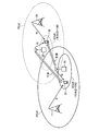
- FIG. 1 is a diagram for explaining the problem.
- base stations 11 and 12 are base stations of carrier A
- base stations 21 and 22 are base stations of carrier B.
- Company A and Company B are different carriers.
- the base station 11 forms a licensed band (licensed band f1) PCell of frequency f1
- the base station 12 forms an unlicensed band (unlicensed band f2) SCell of frequency f2. That is, CA of A company is implemented by the base station 11 and the base station 12 for the communication terminal 31 with which the communication service contract has been made with the A company.
- the base station 21 forms a licensed band (licensed band f3) PCell of frequency f3, and the base station 22 forms an unlicensed band (unlicensed band f2) SCell of frequency f2. That is, the CA of B company is executed by the base station 21 and the base station 22 for the communication terminal 32 that has a communication service contract with the B company.
- the frequencies f1, f2, and f3 are different from each other.
- a communication network is configured for each telecommunications carrier, and if the telecommunications carrier is different, the configured communication network is also different.
- the communication network formed by the company A and the communication network formed by the company B are different communication networks
- the base stations 11 and 12 are included in the communication network formed by the company A
- the base stations 21 and 22 are It is included in the communication network formed by Company B.
- one communication carrier can configure one or a plurality of communication networks.
- “network identification information” that can uniquely identify the communication network is usually assigned to each communication network.
- the cell ID can be freely set independently by the communication carrier.
- company A sets a cell ID of “130” for the SCell of unlicensed band f2
- company B for company S, of unlicensed band f2
- a case where a cell ID of “130” is set is assumed.
- the synchronization signal transmitted from the base station 12 and the synchronization signal transmitted from the base station 22 are the same. That is, it is assumed that the SCells adjacent to each other have the same cell ID and the same synchronization signal. In this case, it is difficult for the communication terminals 31 and 32 to determine whether the SCell having the cell ID “130” is the SCell of the A company or the SCell of the B company.
- each of the communication terminals 31 and 32 measures a combination of the SCell radio channel quality of the company A and the SCell radio channel quality of the company B as the radio channel quality of one SCell. That is, in the communication terminals 31 and 32, the radio channel quality of the SCell is not correctly measured. If the SCell radio channel quality is not measured correctly, it will be difficult to implement CA.
- the frequency of the SCell formed by the base station 12 and the frequency of the SCell formed by the base station 22 are the same in the unlicensed band f2. Therefore, when the distance from the base station 12 and the distance from the base station 22 are different for the communication terminals 31 and 32, the synchronization signal transmitted from the base station 12 and the synchronization signal transmitted from the base station 22 Interference occurs between each other. If interference occurs between the synchronization signals, it may be difficult for the communication terminal to correctly demodulate the received synchronization signal and acquire a correct cell ID. If the cell ID of the SCell is not acquired correctly, it becomes difficult to perform CA.
- the base station forming the PCell requests the selected SCell to set up a line with the communication terminal, and the selected SCell makes a dedicated random access preamble (dedicated random access preamble; Hereinafter, it may be referred to as “DRAP”) and notified to the communication terminal.
- DRAP dedicated random access preamble
- the communication terminal performs random access with the SCell using DRAP notified from the base station.
- random access may be referred to as “RA”.
- the SCell selected by the base station is an SCell of a communication network other than the communication network to which the own station belongs due to duplication of cell IDs between the SCells
- the DRAP notified to the communication terminal is another communication. It will be in the SCell of the network.
- the SCell that receives the DRAP transmitted from the communication terminal (that is, the SCell of the desired communication network) may not be recognized as a DRAP in the first place, and a collision may occur between the DRAPs. That is, RA between the communication terminal and the SCell may fail, and a wireless line between the communication terminal and the SCell may not be set. If the wireless line between the communication terminal and the SCell cannot be set, it becomes difficult to implement CA.
- the SCell to which the line with the communication terminal is set is not the SCell of the desired communication network of the communication terminal.
- the base station exchanges data with the communication terminal using the SCell of the desired communication network. That is, since the SCell in which the line with the communication terminal is set and the SCell used for data exchange between the base station and the communication terminal are different, in the SCell, the data from the base station is the communication terminal. Not reach. Therefore, the implementation of CA becomes difficult.
- the divided user data transmitted by one communication service is divided into a plurality of pieces and transmitted by CA using a plurality of cells (for example, PCell and one SCell), the divided user data is a plurality of different communication. It is difficult to send over the network. That is, it is difficult to implement CA between a plurality of different communication networks.
- the disclosed technology has been made in view of the above, and aims to enable CA using an unlicensed band.
- the wireless communication system includes a first base station that performs communication using a licensed band, a second base station that performs communication using an unlicensed band, and a communication terminal.
- the first base station includes first network identification information that is identification information of a first communication network to which the first base station belongs, and identification information of a second communication network to which the second base station belongs. Based on the second network identification information, the base station with which the communication terminal communicates simultaneously with the first base station is selected from the second base stations.
- CA can be performed using an unlicensed band.
- CA using an unlicensed band can be performed, high-speed transmission can be realized.
- FIG. 1 is a diagram for explaining the problem.
- FIG. 2 is a diagram illustrating an example of the configuration of the wireless communication system according to the first embodiment.
- FIG. 3 is a block diagram illustrating a configuration example of the base station according to the first embodiment.
- FIG. 4 is a block diagram illustrating a configuration example of the physical layer processing unit and the licensed band control unit according to the first embodiment.
- FIG. 5 is a diagram illustrating an example of system information according to the first embodiment.
- FIG. 6 is a diagram illustrating an example of the mapping table.
- FIG. 7 is a diagram illustrating an example of a frame structure.
- FIG. 8 is a diagram illustrating a mapping example of PSS, SSS, and pilot signals in one subframe.
- FIG. 9 is a block diagram illustrating a configuration example of the physical layer processing unit and the unlicensed band control unit according to the first embodiment.
- FIG. 10 is a block diagram illustrating a configuration example of the communication terminal according to the first embodiment.
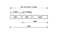
- FIG. 11 is a diagram illustrating a configuration example of IMSI.
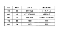
- FIG. 12 is a diagram illustrating an example of MCC and MNC in Japan.
- FIG. 13 is a diagram illustrating a configuration example of the LAI.
- FIG. 14 is a diagram illustrating a configuration example of CGI.
- FIG. 15 is a diagram illustrating a configuration example of a BSIC.
- FIG. 16 is a diagram illustrating a configuration example of RSZI.
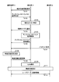
- FIG. 17 is a diagram illustrating an example of a synchronization and wireless channel quality measurement sequence according to the first embodiment.
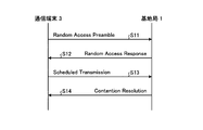
- FIG. 18A is a sequence diagram of Contention based random access procedure.
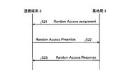
- FIG. 18B is a sequence diagram of non-Contention based random access procedure.
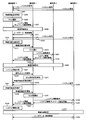
- FIG. 19 is a diagram illustrating an example of an SCell connection sequence in the wireless communication system according to the first embodiment.
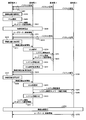
- FIG. 20 is a diagram illustrating an example of a CA processing sequence in the wireless communication system according to the first embodiment.
- FIG. 21 is a diagram illustrating an example of a CA processing sequence in the wireless communication system according to the first embodiment.
- FIG. 22 is a flowchart for explaining CA processing performed by the communication terminal according to the first embodiment.
- FIG. 18A is a sequence diagram of Contention based random access procedure.
- FIG. 18B is a sequence diagram of non-Contention based random access procedure.
- FIG. 19 is a diagram illustrating an example of an SCell connection sequence in the wireless communication system according
- FIG. 23 is a flowchart for explaining CA processing performed by the communication terminal according to the first embodiment.
- FIG. 24 is a hardware configuration diagram of the base station.
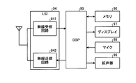
- FIG. 25 is a hardware configuration diagram of the communication terminal.
- FIG. 26 is a diagram illustrating an example of a CA processing sequence in the wireless communication system according to the second embodiment.
- FIG. 27 is a flowchart for explaining the CA process performed by the base station according to the second embodiment.
- FIG. 28 is a block diagram illustrating a configuration example of the CBBU of the base station according to the third embodiment.
- FIG. 29 is a block diagram illustrating a configuration example of the RRH of the base station according to the third embodiment.
- FIG. 30 is a block diagram illustrating a configuration example of a base station according to the fourth embodiment.
- FIG. 24 is a hardware configuration diagram of the base station.
- FIG. 25 is a hardware configuration diagram of the communication terminal.
- FIG. 26 is a diagram illustrating an example of a CA processing sequence in
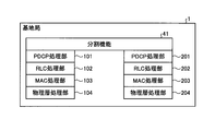
- FIG. 31 is a schematic diagram illustrating processing units and data transfer processing of each layer of the base station.
- FIG. 32A is a diagram illustrating a configuration in which data is divided in a host device.
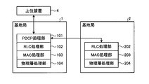
- FIG. 32B is a diagram illustrating a configuration when the PDCP processing unit is shared.
- FIG. 32C is a diagram illustrating a configuration when the PDCP processing unit and the RLC processing unit are shared.
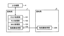
- FIG. 32D is a diagram illustrating a configuration when the PDCP processing unit, the RLC processing unit, and the MAC processing unit are shared.
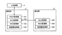
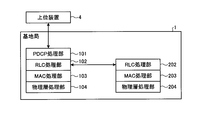
- FIG. 33A is a diagram illustrating a configuration in which data is transferred from a PDCP processing unit of a base station using a licensed band to an RLC processing unit of a base station using an unlicensed band.
- FIG. 32A is a diagram illustrating a configuration in which data is transferred from a PDCP processing unit of a base station using a licensed band to an RLC processing unit of a base station using an unlicensed
- FIG. 33B is a diagram illustrating a configuration in which data is transferred from the PDCP processing unit of the base station using the licensed band to the RLC processing unit of the base station using the unlicensed band.
- FIG. 34A is a diagram illustrating a configuration in which data is divided in a host device in one base station.
- FIG. 34B is a diagram illustrating a configuration when a PDCP processing unit is shared in one base station.
- FIG. 34C is a diagram illustrating a configuration when the PDCP processing unit and the RLC processing unit are shared in one base station.
- FIG. 34D is a diagram illustrating a configuration when a PDCP processing unit, an RLC processing unit, and a MAC processing unit are shared in one base station.
- the wireless communication system, communication terminal, base station, and cell control method disclosed in the present application are not limited by the following embodiments.
- the radio communication system, communication terminal, base station, and cell control method disclosed in the present application are not limited to the LTE system.
- the multiple access scheme is not limited, and for example, TDMA, CDMA, OFDMA, SC-FDMA, NOMA or the like can be adopted as the multiple access scheme.
- FIG. 2 is a diagram illustrating an example of the configuration of the wireless communication system according to the first embodiment.
- the wireless communication system according to the first embodiment includes a base station 1, a base station 2, and a communication terminal 3.
- the base station 1 forms a cell 10 that is a PCell.
- the base station 2 forms a cell 20 that is an SCell.
- the base station 1 and the base station 2 are connected by wire or wireless, and can transmit and receive data to and from each other.
- the base station 1 and the base station 2 may be combined into one base station.
- the base station 1 and the base station 2 are connected inside the apparatus (for example, via an interface or the like inside the apparatus) and can transmit and receive data to and from each other.
- a plurality of CCs are set in the base station 1, and the CA is performed in the CCs of the same base station 1.
- CA is performed in the CCs of the same base station 1.
- DC-HSDPA Dual Cell-High Speed Downlink Packet Access
- DC-HSDPA Dual Cell-High Speed Downlink Packet Access
- the implementation of DC-HSDPA between the base station 1 and another base station is called DB (Dual Band) -HSDPA or DB-DC-HSDPA and is specified.
- 4C-HSDPA using four frequencies is also specified.
- DC-HSDPA DC-HSDPA
- DB-DC-HSDPA DC-HSDPA
- 4C-HSDPA DC-HSDPA
- CA DC-HSDPA
- DB-DC-HSDPA DC-HSDPA
- 4C-HSDPA 4C-HSDPA
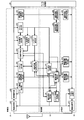
- FIG. 3 is a block diagram illustrating a configuration example of the base station according to the first embodiment.
- the base station 1 includes a PDCP (Packet Data Convergence Protocol) processing unit 101, an RLC (Radio Link Control) processing unit 102, a MAC (Media Access Control) processing unit 103, and a physical layer processing unit 104. . Further, the base station 1 has a licensed band control unit 105.
- the licensed band control unit 105 operates in cooperation with other processing units. Therefore, for convenience of illustration, the licensed band control unit 105 extends over each processing unit, but is actually a processing unit different from each processing unit. However, the part that cooperates with each processing unit can be disassembled and considered as a part of each processing unit.
- the base station 2 includes a PDCP processing unit 201, an RLC processing unit 202, a MAC processing unit 203, and a physical layer processing unit 204.
- the base station 2 has an unlicensed band control unit 205.
- the base station 1 and the base station 2 are connected by wire using, for example, an X2 interface. Further, the base station 1 and the host device 4 are connected by wire using the S1 interface.
- the PDCP processing units 101 and 201 communicate with the host device 4.
- the host device 4 includes, for example, an MME and an S-GW.
- the host device 4 may be considered as a core network.
- the PDCP processing units 101 and 201 have functions of data header information compression, data encryption and decryption (Ciphering and deciphering), and control information security assurance (Integrity protection and integrity verification).
- the PDCP processing unit 101 includes a downlink signal processing unit 111 and an uplink signal processing unit 112.
- the PDCP processing unit 201 includes a downstream signal processing unit 211 and an upstream signal processing unit 212. Since the PDCP processing unit 101 and the PDCP processing unit 201 have the same configuration, the PDCP processing unit 101 will be described below as an example, and the description of the PDCP processing unit 201 is omitted.
- the downlink signal processing unit 111 receives a signal such as user data from the host device 4. Then, the downlink signal processing unit 111 segments a data packet that is a received signal, adds a PDCP header such as a sequence number, and creates a PDCP PDU (RLC SDU). Then, the downlink signal processing unit 111 outputs the processed transmission signal to the downlink signal processing unit 121 of the RLC processing unit 102.
- a signal such as user data from the host device 4. Then, the downlink signal processing unit 111 segments a data packet that is a received signal, adds a PDCP header such as a sequence number, and creates a PDCP PDU (RLC SDU). Then, the downlink signal processing unit 111 outputs the processed transmission signal to the downlink signal processing unit 121 of the RLC processing unit 102.
- the upstream signal processing unit 112 receives an input of a signal such as user data from the upstream signal processing unit 122 of the RLC processing unit 102. Then, the uplink signal processing unit 112 concatenates the received PDCP PDU (RLC SDU), removes the PDCP header, and reproduces the PDCP SDU, that is, the IP packet. Then, the upstream signal processing unit 112 transmits the processed signal to the higher-level device 4.
- a signal such as user data from the upstream signal processing unit 122 of the RLC processing unit 102.
- the uplink signal processing unit 112 concatenates the received PDCP PDU (RLC SDU), removes the PDCP header, and reproduces the PDCP SDU, that is, the IP packet. Then, the upstream signal processing unit 112 transmits the processed signal to the higher-level device 4.
- the PDCP processing unit 101 and the PDCP processing unit 201 communicate using PDCP SDU.
- the RLC processing units 102 and 202 have an ARQ (Auto Repeat Request) function, a control function for signal retransmission processing, and the like.
- the RLC processing unit 102 includes a downstream signal processing unit 121 and an upstream signal processing unit 122.
- the RLC processing unit 202 includes a downlink signal processing unit 221 and an uplink signal processing unit 222. Since the RLC processing unit 102 and the RLC processing unit 202 have the same configuration, the RLC processing unit 102 will be described below as an example, and the description of the RLC processing unit 202 is omitted.
- the downlink signal processing unit 121 of the RLC processing unit 102 receives an input of a PDCP PDU that is a signal processed by the downlink signal processing unit 111 of the PDCP processing unit 101.
- the downlink signal processing unit 121 segments the received PDCP PDU (RLC SDU), adds an RLC header such as a sequence number, and creates an RLC PDU. Then, the downlink signal processing unit 121 outputs the generated RLC PDU to the downlink signal processing unit 131 of the MAC processing unit 103.
- the upstream signal processing unit 122 of the RLC processing unit 102 receives an input of an RLC PDU (MAC SDU) that is a signal processed by the upstream signal processing unit 132 of the MAC processing unit 103.
- the uplink signal processing unit 122 concatenates the received RLC PDU, removes the RLC header, and reproduces the RLC SDU (PDCP PDU). Then, the upstream signal processing unit 122 outputs the reproduced RLC SDU to the upstream signal processing unit 112 of the PDCP processing unit 101.
- the MAC processing units 103 and 203 have a function of performing HARQ (Hybrid ARQ) with the MAC of the communication terminal 3. Further, the MAC processing units 103 and 203 select which communication terminal performs uplink data transmission and downlink data transmission, data amount to be transmitted, wireless resources to be used, modulation scheme, coding rate, and the like. Has a scheduling function. Further, the MAC processing units 103 and 203 have a function of performing RA, radio line control, and the like.
- the MAC processing unit 103 includes a downlink signal processing unit 131 and an uplink signal processing unit 132. Further, the MAC processing unit 203 includes a downlink signal processing unit 231 and an uplink signal processing unit 232. Since the MAC processing unit 103 and the MAC processing unit 203 have the same configuration, the MAC processing unit 103 will be described below as an example, and the description of the MAC processing unit 203 is omitted.
- the downstream signal processing unit 131 of the MAC processing unit 103 receives an input of a MAC SDU (RLC PDU) from the RLC processing unit 102.
- the downlink signal processing unit 131 segments the MAC SDU, adds a MAC header such as a sequence number, and creates a MAC PDU. Further, the downlink signal processing unit 131 performs signal scheduling, that is, allocation to radio resources in accordance with signal scheduling information. Then, the downlink signal processing unit 131 outputs the MAC PDU to the licensed band transmission unit 141 of the physical layer processing unit 104.
- the upstream signal processing unit 132 of the MAC processing unit 103 receives the input of the MAC PDU from the licensed band receiving unit 142 of the physical layer processing unit 104 according to the scheduling. Then, the upstream signal processing unit 132 concatenates the MAC PDUs, removes the MAC header, and reproduces the MAC SDU (RLC PDU). Then, the upstream signal processing unit 132 outputs the reproduced MAC SDU to the upstream signal processing unit 122 of the RLC processing unit 102.
- the physical layer processing units 104 and 204 perform synchronization processing, equalization processing, modulation / demodulation processing, error correction code processing, and RF (Radio Frequency) control in the wireless physical layer.
- the physical layer processing unit 104 includes a licensed band transmission unit 141 and a licensed band reception unit 142.
- the physical layer processing unit 204 includes an unlicensed band transmission unit 241 and an unlicensed band reception unit 242.
- the base station 1 includes a MAC processing unit 103 and a physical layer processing unit 104, and an RNC (Radio Network Controller) includes a PDCP processing unit 101 and an RLC processing unit 102.
- the RLC processing unit 102 further has functions such as handover control.
- the base station 2 has the same configuration as long as it is a W-CDMA system.
- FIG. 4 is a block diagram illustrating a configuration example of the physical layer processing unit and the licensed band control unit according to the first embodiment. However, in FIG. 4, regarding the licensed band control unit 105, only functions necessary for physical layer processing are shown.
- the licensed band reception unit 142 includes a radio reception unit 151, a demodulation / decoding unit 152, a terminal performance information extraction unit 153, a radio channel quality information extraction unit 154, and a radio channel control information extraction unit 155.
- the wireless reception unit 151 receives a signal transmitted from the communication terminal 3 using a licensed band via an antenna. Then, the radio reception unit 151 amplifies the received signal and further converts the radio frequency into a baseband signal. Radio receiving section 151 then outputs the signal converted into the baseband signal to demodulation and decoding section 152.
- the demodulation / decoding unit 152 receives a signal input from the wireless reception unit 151. Then, the demodulation / decoding unit 152 performs demodulation processing on the received signal. Further, the demodulation / decoding unit 152 performs a decoding process on the demodulated signal. Demodulation / decoding section 152 then outputs the signal subjected to each processing to upstream signal processing section 132.
- the terminal performance information extraction unit 153 extracts terminal performance information from the signal transmitted from the demodulation / decoding unit 152.
- the terminal performance information includes information indicating whether or not the unlicensed band of the communication terminal 3 can be used. Then, the terminal performance information extraction unit 153 outputs the extracted terminal performance information to the terminal performance information control unit 156. Note that the availability of the unlicensed band indicates whether communication using the unlicensed band is possible as a function of the terminal, and is different from the availability of use based on the wireless environment such as wireless channel quality. .
- the radio channel quality information extraction unit 154 extracts radio channel quality information including RSRP (Reference Signal Received Power) from the signal transmitted from the demodulation / decoding unit 152. Radio channel quality information extraction section 154 then outputs the extracted radio channel quality information to radio channel control section 157.
- RSRP Reference Signal Received Power
- the radio channel quality is a generic term for received power, pilot received power, received quality, and pilot received quality.
- the received power may be a received electric field strength.
- the radio channel quality is sometimes called radio channel state information (CSI: Channel State Information).
- the pilot reception power is, for example, RSRP in the LTE system, and CPICH RSCP (Common Pilot Channel Received Signal Code Power) in the W-CDMA system.
- the reception quality is, for example, SIR (Signal-noise Ratio).
- the pilot reception quality is, for example, RSRQ (Reference Signal Received Quality) in the LTE system, and CPICH Ec / N0 (Common Pilot Channel received energy per chip divided by the power density) in the W-CDMA system. It is.
- the radio channel quality information extraction unit 154 extracts radio channel quality information of one or a plurality of cells from the signal transmitted from the demodulation / decoding unit 152. Radio channel quality information extraction section 154 then outputs the extracted radio channel quality information to radio channel control section 157.
- the radio channel control information extraction unit 155 extracts a radio channel control signal including the RA preamble from the signal transmitted from the demodulation / decoding unit 152. Next, the radio channel control information extraction unit 155 acquires an RA preamble from the radio channel control signal. Radio channel control information extraction section 155 then outputs the RA preamble to radio channel control section 157.
- the radio network control information extraction unit 155 extracts the input of the scheduled transmission transmitted from the communication terminal 3 as a response to the RA response from the signal transmitted by the demodulation decoding unit 152. Radio channel control information extraction section 155 then outputs the scheduled transmission to radio channel control section 157.
- the radio channel control information extraction unit 155 extracts control information used for radio channel setting in the cell 20 from the signal transmitted from the demodulation / decoding unit 152. Radio channel control information extraction section 155 then outputs the extracted control information to radio channel control section 157.
- the radio network control information extraction unit 155 extracts “incorrect network notification” from the signal transmitted from the demodulation / decoding unit 152. Then, the wireless channel control information extraction unit 155 outputs the extracted erroneous network notification to the wireless channel control unit 157. Details of the erroneous network notification will be described later.
- the licensed band control unit 105 includes a terminal performance information control unit 156, a wireless line control unit 157, a system information management storage unit 158, and a host processing unit 159.
- the terminal performance information control unit 156 determines whether the communication terminal 3 can use the unlicensed band using the terminal performance information. Then, the terminal performance information control unit 156 notifies the wireless line control unit 157 whether or not the communication terminal 3 can use the unlicensed band.
- the radio channel control unit 157 receives the RA preamble input from the radio channel control information extraction unit 155. Then, the wireless line control unit 157 performs control for returning an RA response (random access response) to the RA preamble. For example, the wireless channel control unit 157 performs control for requesting the creation of a TAI (Timing Advanced Indicator) that controls the transmission timing of the communication terminal 3 and the execution of aperiodic wireless channel measurement and wireless channel measurement result report. Implement. Radio channel controller 157 then outputs control information for RA response to radio channel control information generator 160.
- TAI Transmission Advanced Indicator
- the radio line control unit 157 receives the scheduled transmission input from the radio line control information extraction unit 155. Then, the wireless line control unit 157 performs control for transmitting contention resolution to the communication terminal 3. Thereafter, the wireless channel control unit 157 outputs control information for contention resolution to the wireless channel control information creation unit 160.
- the wireless channel control unit 157 instructs the terminal performance information request creating unit 164 to transmit a terminal performance information request after the RA is completed and a wireless channel is set between the local station and the communication terminal 3. Thereafter, the wireless line control unit 157 receives input of information indicating whether or not the communication terminal 3 can use the unlicensed band from the terminal performance information control unit 156. Then, the wireless line control unit 157 identifies the communication terminal 3 using the information on whether or not the unlicensed band can be used, and specifies the terminal category.
- the wireless line control unit 157 has a list in which terminal categories created by categorization based on, for example, whether or not an unlicensed band can be used are registered.
- the radio channel control unit 157 instructs the radio channel control information creating unit 160 to create control information for notifying that the unlicensed band is used.
- the wireless line control unit 157 instructs the wireless line control information creating unit 160 to notify the communication terminal 3 of the terminal category.
- the wireless line control unit 157 notifies the system information management storage unit 158 of the use of the unlicensed band for the communication terminal 3.
- the radio channel control unit 157 determines to perform aperiodic radio channel quality measurement that does not follow the measurement cycle or the measurement result reporting cycle (hereinafter collectively referred to as “measurement cycle”)
- the channel quality measurement is notified to the radio channel control information creation unit 160.
- the radio channel control unit 157 transmits radio channel quality measurement conditions to the radio channel control information creation unit 160.
- the conditions for radio channel quality measurement include, for example, a measurement cycle, radio resources to be measured (for example, the entire system bandwidth or a part of the system bandwidth), and the like.
- the wireless channel control unit 157 determines to perform aperiodic wireless channel quality measurement.
- the radio channel control unit 157 receives the radio channel quality measurement and calculation result input from the radio channel quality information extraction unit 154 as a response to the aperiodic radio channel quality measurement request. Then, the radio channel controller 157 selects a communication terminal that transmits downlink data based on the acquired radio channel quality.
- the radio network controller 157 selects a data amount, radio resources to be used, modulation scheme to be used, coding rate, and the like when performing downlink data transmission to the communication terminal 3.
- the radio resource to be used is a radio resource configured in the frequency axis direction and the time axis direction in the LTE system. In the case of a W-CDMA system, the radio resource to be used is a spreading code.
- radio channel controller 157 outputs the selection result to radio channel control information generator 160.
- the wireless channel control unit 157 receives an input of a pilot signal transmitted from a communication terminal including the communication terminal 3 from the wireless channel control information extraction unit 155. Then, the radio channel controller 157 measures and calculates the uplink radio channel quality from the received pilot signal. Next, the radio channel controller 157 selects a communication terminal that performs uplink data transmission based on the radio channel quality. This process may be generally called scheduling. Note that only the process of selecting a terminal may be referred to as scheduling. Here, a case will be described where the radio channel controller 157 selects the communication terminal 3 as a communication terminal that performs uplink data transmission based on radio channel quality.
- the radio network controller 157 selects the data amount, radio resources to be used, modulation scheme to be used, coding rate, etc. when the communication terminal 3 performs uplink data transmission.
- the radio resource to be used is a radio resource configured in the frequency axis direction and the time axis direction in the LTE system.
- the radio resource to be used is a spreading code.
- the wireless channel control unit 157 monitors the wireless channel quality extracted by the wireless channel quality information extracting unit 154. When the wireless channel quality satisfies a predetermined condition such that the difference between the transmission rate with the communication terminal 3 and a predetermined transmission rate exceeds a threshold value, the wireless channel control unit 157 performs CA. decide. Then, the wireless line control unit 157 notifies the host processing unit 159 of CA implementation.
- the radio channel control unit 157 receives input of radio channel quality information from the radio channel quality information extraction unit 154 with the communication terminal 3 of one or a plurality of cells. Then, the radio channel controller 157 selects an SCell from cells other than the PCell based on the acquired radio channel quality information. For example, the radio channel control unit 157 selects a cell having radio channel quality equal to or higher than the threshold value as the SCell. When there are a plurality of cells having radio channel quality equal to or higher than the threshold, it is preferable to select a cell having the best radio channel quality as the SCell.
- the wireless line control unit 157 invalidates the previous selection result of the SCell and performs reselection of the SCell.
- the wireless network control unit 157 receives an erroneous network notification from the wireless network control information extraction unit 155 when the communication terminal 3 does not match the network identification information of the cell 10 and the network identification information of the cell 20.
- the radio network controller 157 selects the cell 20 as the SCell.
- the radio channel control unit 157 instructs the radio channel control information creation unit 160 to request the control station base station 2 for control information used for radio channel setting.
- the control information used for radio channel setting is, for example, control information used for DRAP or RA allocated to each communication terminal.
- system information is included in the control information used for wireless channel setting.
- the system information includes radio channel quality measurement conditions, cell selection information, neighboring cell information including a cell ID, MBSFN (Multicast Broadcast Single Frequency Network) related information, network identification information, CA related information, and the like.
- the system information includes information broadcasted (transmitted) as control information common to the communication terminal 3 to be connected to or connected to the cell, and information to be connected to or connected to the cell.
- SIB System Information Block
- the wireless channel control unit 157 receives input of control information used for wireless channel setting in the cell 20 from the wireless channel control information extraction unit 155. Then, the radio channel control unit 157 instructs the radio channel control information creation unit 160 to notify control information used for radio channel setting.
- the host processing unit 159 performs control processing in the PDCP processing unit 101, the RLC processing unit 102, and the MAC processing unit 103.
- the licensed band transmission unit 141 includes a terminal performance information request creation unit 164, a radio channel control information creation unit 160, a pilot creation unit 161, a synchronization signal creation unit 162, a system information creation unit 163, a radio transmission unit 165, and an encoding modulation unit 166.
- the terminal performance information request creation unit 164 receives an instruction to transmit a terminal performance information request from the radio channel control unit 157 after the RA is completed and a radio channel is set between the local station and the communication terminal 3. Then, the terminal performance information request creation unit 164 creates a terminal performance information request. Thereafter, the terminal performance information request creation unit 164 outputs the created terminal performance information request to the encoding modulation unit 166 and transmits it to the communication terminal 3.
- the radio channel control information creation unit 160 receives input of control information for RA response from the radio channel control unit 157. Then, the radio network control information creation unit 160 creates an RA response using the acquired control information. Thereafter, the radio network control information creation unit 160 outputs the created RA response to the encoding modulation unit 166 and transmits it to the communication terminal 3.
- the radio channel control information creation unit 160 receives input of control information for contention resolution from the radio channel control unit 157. Then, the wireless channel control information creation unit 160 creates contention resolution using the acquired control information. After that, the radio network control information creation unit 160 outputs the created contention resolution to the encoding modulation unit 166 and transmits it to the communication terminal 3.
- the radio channel control information creation unit 160 receives a radio channel quality measurement notification that does not follow the measurement cycle from the radio channel control unit 157. In this case, the radio channel control information creation unit 160 also acquires the radio channel quality measurement conditions from the radio channel control unit 157. Radio channel control information creating section 160 creates a radio channel quality measurement request using the radio channel quality measurement conditions. Thereafter, the radio channel control information creation unit 160 outputs the created radio channel quality measurement request to the encoding modulation unit 166 and transmits it to the communication terminal 3.
- the radio channel control information creating unit 160 inputs the selection result such as the data amount, radio resource to be used, modulation scheme to be used, and coding rate when performing downlink data transmission to the communication terminal 3. Received from the control unit 157. Radio channel control information creating section 160 creates downlink control information including the selection result. Thereafter, radio channel control information creating section 160 outputs downlink control information including the created selection result to coding modulation section 166 and transmits it to communication terminal 3.
- the selection result such as the data amount, radio resource to be used, modulation scheme to be used, and coding rate when performing downlink data transmission to the communication terminal 3.
- the radio channel control information creating unit 160 inputs the selection results such as the data amount, the radio resource to be used, the modulation scheme to be used, and the coding rate when the communication terminal 3 performs uplink data transmission. Receive from. Radio channel control information creation section 160 creates uplink control information including a selection result. Thereafter, radio channel control information creating section 160 outputs uplink control information including the created selection result to coding modulation section 166 and transmits it to communication terminal 3.
- the wireless channel control information creation unit 160 receives an instruction for creating control information for notifying that the unlicensed band is used from the wireless channel control unit 157. Radio channel control information creation section 160 creates an unlicensed band use notification. After that, the radio network control information creation unit 160 outputs the created unlicensed band use notification to the encoding modulation unit 166 and transmits it to the communication terminal 3. Further, the wireless channel control information creating unit 160 receives an instruction to notify the communication terminal 3 of the terminal category from the wireless channel control unit 157. Radio channel control information creating section 160 creates control information for notifying the terminal category. Thereafter, radio channel control information creating section 160 outputs control information for notifying the terminal category to coding modulation section 166 and transmits it to communication terminal 3.
- the radio channel control information creating unit 160 receives from the radio channel control unit 157 an instruction to request the base station 2 of control information used for radio channel setting. Then, the radio channel control information creating unit 160 creates a request for control information used for radio channel setting. Thereafter, the radio channel control information creating unit 160 transmits a request for the created control information used for radio channel setting to the base station 2 via the X2 interface.
- the radio channel control information creation unit 160 receives an instruction for notification of control information used for radio channel setting in the cell 20 from the radio channel control unit 157.
- Radio channel control information creating section 160 creates control information for notifying control information used for radio channel setting in cell 20.
- the radio channel control information creating unit 160 transmits control information for notifying control information used for radio channel setting in the created cell 20 to the base station 2 via the X2 interface.
- the radio network control information creating unit 160 may notify the communication terminal 3 of the cell information of the cell 20 including cell control information such as a cell ID, for example. You may notify the information which shows the communication network to which it belongs.
- the system information management storage unit 158 stores and manages system information including radio channel quality measurement conditions, cell selection information, neighboring cell information including a cell ID, MBSFN related information, network identification information, CA related information, and the like.
- the contents of the system information stored in the system information management storage unit 158 are shown in FIG. 5, for example.
- FIG. 5 is a diagram illustrating an example of system information according to the first embodiment.
- the conditions for wireless channel quality measurement include, for example, information on the bandwidth to be measured, the measurement period, and the cell to be measured.
- the network identification information is information indicating the communication network to which the base station (cell) belongs.
- the cell ID is also called a cell identifier, C (Cell) -ID, physical cell ID, PC (Physical Cell) -ID, or PCID.
- the cell ID is an ID for identifying a cell.
- the cell ID is used for identifying a cell in radio channel quality measurement, handover, or the like.
- the communication terminal 3 can recognize the cell ID of the cell by receiving the synchronization signal in the standby cell or the connected cell.
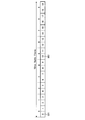
- this cell ID is set as follows in the LTE system. That is, there are 168 groups composed of three cell IDs, and a total of 504 cell IDs can be set.
- the cell ID is calculated by the following formula (1).
- N (2) ID is interpreted as a group number of the cell ID
- N (1) ID is interpreted as a number in the group.
- the system information creation unit 163 acquires the network identification information of the base station 1 (cell 10, PCell) from the system information management storage unit 158 after line setting or before performing RA. Then, the system information creation unit 163 creates system information using the acquired network identification information or the like. This system information includes control information related to RA. Thereafter, the system information creation unit 163 outputs the system information including the network identification information to the encoding modulation unit 166 and transmits it to the communication terminal 3.
- system information creation unit 163 acquires the conditions for measuring the wireless channel quality from the system information management storage unit 158. Then, the system information creation unit 163 creates the acquired measurement conditions for wireless channel quality measurement as system information. Thereafter, system information creation section 163 outputs system information including measurement conditions for radio channel quality measurement to encoding modulation section 166 and transmits the information to communication terminal 3. Note that the system information creation unit 163 notifies the communication terminal of the system information as individual control information for each communication terminal, as well as all or one of the communication terminals that are waiting (camping) in the cell 10 or connected to the cell 10. May be transmitted as common control information common to some communication terminals. Further, the system information may include a measurement bandwidth, cell selection priority, and the like.
- the synchronization signal creation unit 162 calculates a synchronization signal based on the cell ID stored in the system information management storage unit 158 (that is, the cell ID of the PCell).
- the synchronization signal may be composed of one signal (symbol), but is generally composed of a plurality of signals (symbols). Therefore, the synchronization signal creation unit 162 calculates a synchronization signal or a synchronization signal string (hereinafter collectively referred to as “synchronization signal”). Thereafter, the synchronization signal creation unit 162 outputs the created synchronization signal to the encoding modulation unit 166 and transmits it to the communication terminal 3.
- two synchronization signals are defined as synchronization signals.
- PSS Primary Synchronization Signal
- SSS Secondary Synchronization Signal
- the pilot creation unit 161 calculates a pilot signal.
- a pilot signal (pilot, pilot symbol) may be composed of one signal (symbol), but is generally composed of a plurality of signals (symbols). Therefore, pilot creation section 161 calculates a pilot signal or a pilot signal sequence (hereinafter collectively referred to as “pilot signal”). Then, pilot creation section 161 outputs the created pilot signal to coding modulation section 166 and transmits it to communication terminal 3.
- pilot signal a pilot signal or a pilot signal sequence
- the calculation method of PSS is defined by the following mathematical formula (2) and the following table. That is, the PSS is calculated based on the cell ID group number N (2) ID .
- PSS is a Zadoff-Chu sequence (Zadoff-Chu code).
- the Zadoff-Chu sequence is CAZAC (Constant Amplitude Zero Auto Correlation Waveform), which is a 1's complement periodic complex signal and a sequence with zero autocorrelation.
- the PSS is expressed by mapping 62 complex signals calculated as described above in the frequency axis direction (subcarrier direction) of OFDMA (Orthogonal Frequency-Division Multiple Access). Also, the PSS is not scrambled.
- mapping of the 62 complex signals is performed according to the following equation (3).
- (k, l) is a resource element in an OFDMA symbol used for PSS transmission.
- the PSS is arranged at ⁇ 31 symbols from the center frequency center of 6 RBs. PSS is not arranged in 5 symbols at both ends.
- the communication terminal 3 can identify the head of the slot because the PSS is arranged at the last symbol in the time axis direction. That is, the communication terminal 3 can synchronize the slots according to the following formula (4).
- the SSS calculation method is performed according to the following procedure.
- D (0),..., D (61) representing SSS are two binary sequences of length 31 obtained using a scramble sequence given by PSS. These two 31-length binary sequences defining the SSS are defined between subframes 0 and 5 according to the following equation (5).
- the SSS can also be interpreted as a sequence obtained by scrambling the calculated sequence.
- n 0 ⁇ n ⁇ 30.
- m 0 and m 1 are expressed as the following formula (6) using the cell ID group N (1) ID .
- FIG. 6 is a diagram illustrating an example of the mapping table. As shown in FIG. 6, the mapping table shows the correspondence between the cell ID group N (1) ID and m 0 and m 1 .
- c 0 (n) and c 1 (n), which are two scramble sequences depending on PSS, are expressed by the following formula (9).
- N (2) ID ⁇ ⁇ 0, 1, 2 ⁇ corresponds to any one of the cell ID groups N (1) ID . Furthermore, each term satisfies the following formula (10).
- m 0 and m 1 are values obtained from the mapping table of FIG. Each term satisfies the following formula (12).
- SSS is expressed by different calculation formulas when transmitting with subframe number 0 and slot number 1 and when transmitting with subframe number 5 and slot number 11. Furthermore, SSS has different calculation formulas for the odd-numbered and even-numbered complex signals to be generated.
- SSS is a signal sequence composed of 62 complex numbers as in PSS.
- c 0 (n) and c 1 (n) are an M sequence (M sequence, maximum length sequence) or a PN (Pseudo Noise) sequence (pseudo noise sequence), and the group number N ( 1) N (2 a number in the ID) are those calculated by using the ID.
- S 0 (m0) (n) and S 1 (m1) (n) are also M-sequences, and the group numbers to which the cell ID belongs N (1) ID and N (1) ID and FIG. Calculated from m 0 and m 1 derived from the mapping table.
- a sequence d (n) representing SSS is mapped to a resource element as represented by the following formula (13).
- the resource element (k, l) is expressed by the following formula (14).
- the SSS is arranged in the symbol immediately before the end of slot 1 and slot 11.
- the last symbol is N DL sym -1.
- “DL” Down Link
- “Symb” is Symbol, which indicates a symbol in the time axis direction.
- the SSS is arranged at ⁇ 31 symbols from the center in the frequency axis direction, that is, the center frequency of 6 RBs in the center of the bandwidth. Further, since the SSS transmitted between the slot 1 and the slot 11 is different, the head of the radio frame can be specified.
- a cell-specific reference signal (hereinafter also referred to as “CRS”) that is a pilot signal common to cells, that is, a communication signal that is common to communication terminals connected to or about to connect to the cell will be described.
- CRS cell-specific reference signal
- a pilot signal calculation method is similarly defined for a UE-specific reference signal (also referred to as a dedicated reference signal (DRS)) which is a pilot signal for each communication terminal.
- a pilot signal calculation method is also defined for a pilot signal for transmitting MBMS (Multimedia Broadcast and Multicast Service) data. The disclosed technique can also be applied when a pilot signal for each communication terminal or a pilot signal for transmitting MBMS data is used.
- MBMS Multimedia Broadcast and Multicast Service
- the pilot signal is expressed by the following formula (15).
- n s is the slot number of the radio frame
- l is the OFDMA symbol number of the slot.
- c (i) in the equation is a Gold code (Gold) of pseudo-noise codes (PN code, pseudo-random noise sequence, pseudo-random sequence) whose initial value is represented by the following formula (16A). sequence).
- the Gold code is generated by connecting two PN codes (M series) having different initial values.
- Formula (16A) is calculated based on 1-bit information indicating the slot number Ns, ID, and CP length.
- the gold code is calculated by the following equation (16B).
- the Gold code has two initial values, one of which is represented by the mathematical formula (16A).
- pilot signal is mapped to a (p) k, l used as a reference symbol for the antenna port p in the slot ns defined by the following equation (17).
- ⁇ is expressed by the following formula (18). The same applies to ⁇ shift .
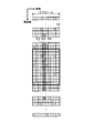
- FIG. 7 is a diagram illustrating an example of a frame structure.
- FIG. 8 is a diagram illustrating a mapping example of PSS, SSS, and pilot signals in one subframe.
- FDD Frequency Division Duplex
- Fig. 7 The numbers in the upper part of Fig. 7 indicate the subframe numbers. Further, the lower number in FIG. 7 represents the slot number of the time slot. As shown in FIG. 7, a 10 ms radio frame has 10 subframes. Each subframe is assigned two slots.
- FIG. 8 shows a state where slot 0 is enlarged.
- a frame 511 in FIG. 8 indicates resource elements. Further, FIG. 8 represents frequency in the vertical direction and time in the horizontal direction.
- Area 512 is the sixth symbol of slot 0, and is mapped with SSS.
- Area 513 is the seventh symbol of slot 0, and PSS is mapped to it. In the region 514, a pilot signal is mapped.
- the coding modulation unit 166 includes the downlink signal processing unit 131, the terminal performance information request creation unit 164, the radio channel control information creation unit 160, the pilot creation unit 161, the synchronization signal creation unit 162, and the system information creation unit 163. Receives various signals from.
- the encoding modulation unit 166 performs encoding and modulation on the input signal. Furthermore, the encoding modulation unit 166 maps the input signal to a radio frame, slot, or subframe.
- the encoding modulation unit 166 outputs the mapped signal to the wireless transmission unit 165.
- the radio transmission unit 165 receives an input of a signal mapped to a radio frame, slot, or subframe from the encoding modulation unit 166. Then, the radio transmission unit 165 converts the frequency of the mapped signal into a radio frequency. Further, the wireless transmission unit 165 amplifies the mapped signal. Thereafter, the wireless transmission unit 165 transmits the mapped signal to the communication terminal 3 through the antenna using the licensed band.
- FIG. 9 is a block diagram illustrating a configuration example of the physical layer processing unit and the unlicensed band control unit according to the first embodiment.
- the base station 2 performs the following processing on the SCell.
- the unlicensed band receiving unit 242 includes a radio receiving unit 251, a demodulation / decoding unit 252, a radio channel quality information extracting unit 254, and a radio channel control information extracting unit 255.
- the wireless reception unit 251 receives a signal transmitted from the communication terminal 3 using an unlicensed band via an antenna. Then, the radio reception unit 251 amplifies the received signal and further converts the radio frequency into a baseband signal. Radio receiving section 251 then outputs the signal converted to the baseband signal to demodulation and decoding section 252.
- the demodulation / decoding unit 252 receives a signal input from the wireless reception unit 251. Then, the demodulation / decoding unit 252 performs demodulation processing on the received signal. Further, the demodulation / decoding unit 252 performs a decoding process on the demodulated signal. Then, the demodulation / decoding unit 252 outputs the signal subjected to each processing to the uplink signal processing unit 232.
- the radio channel quality information extraction unit 254 extracts radio channel quality information including RSRP from the signal transmitted from the demodulation / decoding unit 252. Radio channel quality information extraction section 254 then outputs the extracted radio channel quality information to radio channel control section 257.
- the radio channel control information extraction unit 255 extracts a radio channel control signal including the RA preamble from the signal transmitted from the demodulation / decoding unit 252. Next, the radio channel control information extraction unit 255 acquires the RA preamble from the radio channel control signal. Then, the radio channel control information extraction unit 255 outputs the RA preamble to the radio channel control unit 257.
- the unlicensed band control unit 205 includes a wireless line control unit 257, a system information management storage unit 258, and a host processing unit 259.
- the radio channel control unit 257 receives a request for control information used for radio channel setting such as DRAP from the radio channel control information extraction unit 255. Radio channel controller 257 then outputs control information used for radio channel setting to radio channel control information generator 260. Further, the wireless line control unit 257 acquires a system information request from among requests for control information used for wireless line setting. Then, the wireless line control unit 257 outputs a system information request to the system information creation unit 263 via the system information management storage unit 258.
- the radio line control unit 257 receives an input of the RA preamble from the radio line control information extraction unit 255. Then, the radio network controller 257 performs control for returning an RA response to the RA preamble.
- the wireless channel control unit 257 performs creation of a TAI that controls the transmission timing of the communication terminal 3, control for requesting the execution of aperiodic wireless channel measurement and a wireless channel measurement result report, and the like. Radio channel controller 257 then outputs control information for RA response to radio channel control information generator 260.
- the radio channel control unit 257 determines to perform radio channel quality measurement that does not conform to the measurement cycle, the radio channel control unit 257 notifies the radio channel control information creation unit 260 of the radio channel quality measurement. In this case, the radio channel controller 257 transmits radio channel quality measurement conditions to the radio channel control information generator 260.
- the radio channel control unit 257 receives the radio channel quality measurement and calculation result input from the radio channel control information extraction unit 255 as a response to the aperiodic radio channel quality measurement request. Then, the radio channel controller 257 selects a communication terminal that transmits downlink data based on the acquired radio channel quality. Here, a case where the wireless line control unit 257 selects the communication terminal 3 will be described. Then, the radio network controller 257 selects a data amount, radio resources to be used, modulation scheme to be used, coding rate, and the like when performing downlink data transmission to the communication terminal 3. Next, radio channel controller 257 outputs the selection result to radio channel control information generator 260.
- the wireless channel control unit 257 receives an input of a pilot signal transmitted from a communication terminal including the communication terminal 3 from the wireless channel control information extraction unit 255. Then, the radio channel controller 257 measures and calculates the uplink radio channel quality from the received pilot signal. Next, the radio channel controller 257 selects a communication terminal that performs uplink data transmission based on the radio channel quality.
- the radio channel controller 257 selects the communication terminal 3 as a communication terminal that performs uplink data transmission based on radio channel quality.
- the radio network controller 257 selects the data amount, radio resources to be used, modulation scheme to be used, coding rate, etc. when the communication terminal 3 performs uplink data transmission. Thereafter, the wireless channel control unit 257 outputs the selection result to the wireless channel control information creation unit 260.
- the host processing unit 259 performs control processing in the PDCP processing unit 201, the RLC processing unit 202, and the MAC processing unit 203.
- the unlicensed band transmission unit 241 includes a radio channel control information creation unit 260, a pilot creation unit 261, a synchronization signal creation unit 262, a system information creation unit 263, a radio transmission unit 265, and a coded modulation unit 266.
- the radio channel control information creation unit 260 receives the control information input for the RA response from the radio channel control unit 257. Then, the radio network control information creation unit 260 creates an RA response using the acquired control information. Thereafter, radio channel control information creating section 260 outputs the created RA response to coded modulation section 266 and transmits it to communication terminal 3.
- the radio channel control information creation unit 260 receives a radio channel quality measurement notification that does not follow the measurement cycle from the radio channel control unit 257. In this case, the radio channel control information creating unit 260 also acquires the radio channel quality measurement conditions from the radio channel control unit 257. Radio channel control information creating section 260 creates a radio channel quality measurement request using the radio channel quality measurement conditions. Thereafter, the radio channel control information creation unit 260 outputs the created radio channel quality measurement request to the encoding modulation unit 266 and transmits it to the communication terminal 3.
- the radio channel control information creating unit 260 inputs the selection results such as the amount of data, radio resources to be used, modulation scheme to be used, and coding rate when performing downlink data transmission to the communication terminal 3. Received from the control unit 257. Radio channel control information creation section 260 creates downlink control information including the selection result. Thereafter, the radio network control information creation unit 260 outputs the downlink control information including the created selection result to the encoding modulation unit 266 and transmits it to the communication terminal 3.
- the radio channel control information creating unit 260 inputs a selection result such as a data amount, a radio resource to be used, a modulation scheme to be used, and a coding rate when the communication terminal 3 performs uplink data transmission. Receive from. Radio channel control information creating section 260 creates uplink control information including the selection result. Thereafter, radio channel control information creating section 260 outputs uplink control information including the created selection result to coding modulation section 266 and transmits it to communication terminal 3.
- a selection result such as a data amount, a radio resource to be used, a modulation scheme to be used, and a coding rate when the communication terminal 3 performs uplink data transmission.
- the system information management storage unit 258 stores and manages radio channel quality measurement conditions, cell selection information, neighboring cell information, MBSFN related information, network identification information, CA related information, and the like.
- the system information creation unit 263 receives a system information request from the wireless line control unit 257 via the system information management storage unit 258.
- the system information creation unit 263 acquires the network identification information of the base station 2 (cell 20, SCell) from the system information management storage unit 258. Then, the system information creation unit 263 creates system information using the acquired network identification information or the like. This system information includes control information related to RA. Thereafter, the system information creation unit 263 transmits system information including network identification information to the base station 1 via the X2 interface.
- the system information creation unit 263 may output system information including network identification information to the encoding / modulation unit 266 and transmit it to the communication terminal 3.
- the synchronization signal creation unit 262 acquires the cell ID of the peripheral cell of the communication terminal 3 from the system information management storage unit 258. Then, the synchronization signal generator 262 calculates a synchronization signal. Thereafter, the synchronization signal generation unit 262 outputs the generated synchronization signal to the encoding modulation unit 266 and transmits it to the communication terminal 3.
- the pilot creation unit 261 calculates a pilot signal after an unlicensed band use notification is transmitted to the communication terminal 3. Then, pilot creation section 261 outputs the created pilot signal to coded modulation section 266 and transmits it to communication terminal 3.
- the wireless channel control unit 257 receives from the wireless channel quality information extraction unit 254 an input of wireless channel quality information of a signal received by the wireless reception unit 251 at an unlicensed band frequency. Then, the radio network controller 257 determines whether a significant radio signal is present instead of noise in the signal received at the frequency of the unlicensed band.
- the radio line control unit 257 indicates that a significant radio signal exists. It is determined that the user is using it. In this case, the wireless line control unit 257 does not perform transmission using the frequency for a certain period.
- a significant radio signal means that it is not noise such as thermal noise.
- the radio network controller 257 checks whether the other person is using the unlicensed band at another frequency as well. To do. Alternatively, the wireless line control unit 257 confirms whether or not another person is using after a predetermined time has passed. This fixed time may be regulated by law.
- the wireless channel control unit 257 transmits a synchronization signal or pilot transmission (notification) via the system information management storage unit 258. And instructing the pilot creating unit 261.
- a method for confirming that there is no collision before transmission is called LBT (Listen Before Talk) or CSMA / CA.
- the encoding modulation unit 266 receives various signals from the downlink signal processing unit 231, the radio channel control information creation unit 260, the pilot creation unit 261, the synchronization signal creation unit 262, and the system information creation unit 263.
- the encoding modulation unit 266 performs encoding and modulation on the input signal. Furthermore, the encoding modulation unit 266 maps the input signal to a radio frame, slot, or subframe.
- the encoding modulation unit 266 outputs the mapped signal to the wireless transmission unit 265.
- the radio transmission unit 265 receives an input of a signal mapped to a radio frame, slot, or subframe from the encoding modulation unit 266. Then, the radio transmission unit 265 converts the frequency of the mapped signal into a radio frequency. Further, the wireless transmission unit 265 amplifies the mapped signal. Thereafter, the wireless transmission unit 265 transmits the mapped signal to the communication terminal 3 through the antenna using the unlicensed band.
- the same data transmission control is performed for both the PCell and the SCell.
- the user data may not be transmitted in the PCell, but the user data may be transmitted only in the SCell.
- the base station 1 notifies the communication terminal 3 of the network identification information of the base station 2 (cell 20)
- the system information is transmitted only by the PCell, and the system information is not transmitted by the SCell. Also good.
- FIG. 10 is a block diagram illustrating a configuration example of the communication terminal according to the first embodiment.
- the communication terminal 3 includes a reception unit 31, a control unit 32, a transmission unit 33, and a baseband processing unit 34.
- the communication terminal 3 is a communication terminal that can communicate using both the licensed band and the unlicensed band at the same time. That is, the communication terminal 3 is a communication terminal capable of communicating simultaneously with both the licensed band base station 1 (PCell) and the unlicensed band base station 2 (SCell).
- PCell licensed band base station 1
- SCell unlicensed band base station 2
- the reception unit 31 includes a radio reception unit 301, a demodulation / decoding unit 302, a system information extraction unit 303, a radio channel control information extraction unit 304, a pilot extraction unit 305, a synchronization control unit 306, and a synchronization signal extraction unit 307. Furthermore, the reception unit 31 includes a cell ID extraction unit 308, a terminal performance information request extraction unit 309, a radio channel quality measurement unit 310, a synchronization signal creation unit 311 and a pilot calculation unit 312.
- the wireless receiving unit 301 receives signals transmitted from the base stations 1 and 2 via an antenna.
- the radio reception unit 301 receives a signal transmitted from the base station 1 (cell 10, PCell) using a licensed band.
- wireless receiving part 301 receives the signal transmitted from the base station 2 (cell 20, SCell) using an unlicensed band.
- the wireless reception unit 301 receives an instruction of the frequency band to be received from the terminal setting control unit 321.
- the radio reception unit 301 amplifies the received signal and further converts the radio frequency into a baseband signal.
- Radio receiving section 301 then outputs the signal converted into the baseband signal to demodulation and decoding section 302.
- the demodulator / decoder 302 receives a signal input from the wireless receiver 301. Then, the demodulation / decoding unit 302 performs demodulation processing on the received signal. Further, the demodulation / decoding unit 302 performs a decoding process on the demodulated signal. The demodulation and decoding unit 302 performs demodulation and decoding by a method corresponding to a predetermined modulation and coding method or a modulation and coding method instructed from the terminal setting control unit 321. Then, the demodulation / decoding unit 302 outputs the signal subjected to each processing to the baseband processing unit 34.
- the system information extraction unit 303 extracts the system information transmitted from the base station 1 or the base station 2 from the signal transmitted from the demodulation / decoding unit 302. Then, the system information extraction unit 303 stores the extracted system information in the system information storage unit 323. Further, the system information extraction unit 303 outputs the extracted system information to the terminal setting control unit 321, the cell selection control unit 322, and the radio line control unit 324.
- the system information extracted by the system information extraction unit 303 includes network identification information.
- Radio channel control information extraction section 304 extracts L (Layer) 1 / L2 control information transmitted from base station 1 or base station 2 by PDCCH from the signal transmitted from demodulation and decoding section 302.
- This control information includes information indicating allocation of UL (Up Link) radio resources, modulation modulation schemes to be applied, and the like. Further, this control information includes an unlicensed band use notification.
- Radio channel control information extraction section 304 then outputs the extracted control information to radio channel control section 324.
- radio channel control information extraction unit 304 extracts a radio channel quality measurement request from the signal transmitted from the demodulation / decoding unit 302. Radio channel control information extraction section 304 then outputs the extracted radio channel quality measurement request to radio channel control section 324.
- the radio channel control information extracting unit 304 extracts the radio channel control request transmitted from the base station 1 or the base station 2 from the signal transmitted from the demodulation / decoding unit 302. Then, the radio channel control information extraction unit 304 outputs a radio channel control request to the radio channel quality measurement unit 310 and the radio channel control unit 324.
- the pilot extraction unit 305 extracts a pilot signal from the signal transmitted from the demodulation / decoding unit 302 based on the radio frame and slot timing detected by the synchronization control unit 306. Pilot extraction section 305 then outputs the extracted pilot signal to synchronization control section 306 and radio channel quality measurement section 310.
- the pilot signal is a reference signal (RS).
- the synchronization signal extraction unit 307 extracts the synchronization signal transmitted by the base station 1 using PSS and SSS from the signal transmitted from the demodulation decoding unit 302 for each CC. Then, the synchronization signal extraction unit 307 outputs the synchronization signal to the cell ID extraction unit 308 and the synchronization control unit 306.
- the synchronization control unit 306 detects the radio frame timing and the slot timing based on the synchronization signal extracted by the synchronization signal extraction unit 307. Then, the synchronization control unit 306 notifies the terminal setting control unit 321 and the pilot extraction unit 305 of the detected radio frame and slot timing. The synchronization control unit 306 feeds back the detected radio frame and slot timing to the synchronization signal extraction unit 307.
- the synchronization control unit 306 receives the pilot input calculated by the pilot calculation unit 312. Synchronization control section 306 performs symbol synchronization based on the pilot signal extracted by pilot extraction section 305 and the pilot calculated by pilot calculation section 312. Symbol synchronization refers to synchronization at the start timing of a symbol.
- the cell ID extraction unit 308 receives the synchronization signal input from the synchronization signal extraction unit 307. Next, the cell ID extraction unit 308 identifies a cell ID from the PSS and SSS. For example, the cell ID extraction unit 308 can derive the cell ID of the base station 1 based on two synchronization signals of PSS and SSS transmitted from the base station 1. Then, the cell ID extraction unit 308 outputs the identified cell ID to the synchronization signal generation unit 311, the pilot calculation unit 312, and the cell selection control unit 322.
- the synchronization signal creation unit 311 receives the cell ID input from the cell ID extraction unit 308. Then, the synchronization signal creation unit 311 creates a synchronization signal based on the acquired cell ID. Thereafter, the synchronization signal creation unit 311 outputs the created synchronization signal to the synchronization control unit 306.
- the pilot calculation unit 312 receives the cell ID input from the cell ID extraction unit 308. Then, the pilot calculation unit 312 calculates a pilot based on the acquired cell ID. Then, pilot calculation section 312 outputs the calculated pilot to synchronization control section 306 and radio channel quality measurement section 310.
- the synchronization control unit 306 performs synchronization with the base station 1 to be measured in advance. This is for identifying the pilot signal from other signals and identifying the pilot signal itself.
- the synchronization control unit 306 identifies the head of the radio frame based on the synchronization signal transmitted from the base station 1. This is sometimes called frame synchronization. Furthermore, the synchronization control unit 306 identifies the start of a radio frame, the start of a subframe that constitutes the radio frame, or the start of a slot using a synchronization signal. Identification of the head of a subframe or the head of a slot constituting a radio frame is sometimes called frame synchronization or slot synchronization.
- the synchronization control unit 306 calculates the correlation between the synchronization signal created by the synchronization signal creation unit 311 and the synchronization signal received from the base station 1 in accordance with a method for creating a synchronization signal shared in advance between the base station 1 and the communication terminal 3.
- the synchronization signal sequence is identified, and the head of the sequence is found.
- the synchronization control unit 306 calculates the head of the frame or slot.
- the synchronization signal is usually composed of a plurality of signals, and is not a single signal (one symbol) but a signal sequence composed of a plurality of signals (a plurality of symbols).
- the communication terminal 3 can calculate or identify cell information by identifying a synchronization signal sequence.
- the synchronization signal sequence includes a cell ID (CID) or a P-ID (Physical Cell Identification).
- the synchronization control unit 306 performs symbol synchronization using the pilot signal.
- the pilot signal sequence calculation method is shared in advance between the base station 1 and the communication terminal 3 as in the identification of the synchronization signal. Then, synchronization control section 306 performs symbol synchronization by comparing the pilot signal received from base station 1 with the pilot calculated by pilot calculation section 312 and calculating the correlation.
- the pilot calculation unit 312 can calculate the pilot signal based on the cell ID derived from the synchronization signal by the cell ID extraction unit 308, thereby reducing the time spent for symbol synchronization. In other words, if the synchronization signal is received and the cell ID is not derived, the time spent for symbol synchronization becomes long.
- the pilot extraction unit 305, the synchronization control unit 306, and the synchronization signal extraction unit 307 receive synchronization signals and pilot signals from neighboring cells and perform synchronization. Do.
- the terminal performance information request extraction unit 309 extracts the terminal performance information request transmitted from the base station 1 from the signal transmitted from the demodulation decoding unit 302. Then, the terminal performance information request extraction unit 309 outputs the extracted terminal performance information request to the terminal performance information control unit 326.
- Radio channel quality measuring section 310 receives the pilot input calculated by pilot calculating section 312. Radio channel quality measuring section 310 receives a pilot signal input from pilot extracting section 305. Radio channel quality measurement section 310 measures the radio channel quality using the acquired pilot signal and the pilot calculated by pilot calculation section 312.
- the radio channel quality measurement unit 310 uses, for example, pilot received power (RSRP), pilot received quality (RSRQ), radio channel quality (Channel Quality) or SIR (Signal to Interference and Ratio) as the radio channel quality. Measure and calculate the radio link quality from the measurement result.
- a radio channel quality index CQI: Channel Quality Indicator
- SINR Signal to Interference and Noise Ratio
- the radio channel quality measurement unit 310 measures received power (received electric field strength) using a pilot signal. Radio channel quality measurement section 310 notifies cell selection control section 322 of the measurement result.
- the pilot signal is defined by a cell common reference signal (CRS) common to multiple communication terminals within a cell and a dedicated pilot signal (DRS: Dedicated Reference Signal) assigned to each communication terminal.
- CRS cell common reference signal
- DRS Dedicated Reference Signal
- a pilot signal for position measurement PRS: Positioning Reference Signal
- CSI RS Channel State Information Reference Signal
- the common pilot signal may also be called Common Reference Signal, Cell specific pilot, or Common Pilot.
- the dedicated pilot signal may be called Dedicated pilot or UE specific RS.
- the pilot signal for position measurement may be called positioning pilot or Positioning RS.
- the pilot signal for measuring the radio channel quality is sometimes called “Channel state information pilot”.
- the radio channel quality measurement unit 310 may perform measurement using any of these pilot signals.
- radio channel quality measurement section 310 measures radio channel quality using a known signal, that is, a signal determined in advance between base station 1 or base station 2 and communication terminal 3 or in a radio communication system. May be.
- a normal pilot signal may be a signal intended for demodulation or a signal intended for radio channel quality measurement.
- a signal for the purpose of demodulation is also called an individual pilot signal or a demodulated pilot (demodulation pilot).
- a signal for measuring the radio channel quality is also called a common pilot signal.
- the synchronization control unit 306 and the synchronization control unit 306 are synchronized with each other via the pilot extraction unit 305.
- the signal extraction unit 307 is instructed to execute synchronization.
- the control unit 32 includes a terminal setting control unit 321, a cell selection control unit 322, a system information storage unit 323, a radio channel control unit 324, a terminal performance information storage unit 325, and a terminal performance information control unit 326.
- the terminal setting control unit 321 receives system information input from the system information extraction unit 303. And the terminal setting control part 321 performs the following control based on system information.
- the terminal setting control unit 321 determines the radio resource allocated to the communication terminal 3 based on the control information specified by the radio channel control unit 324 and also determines the applied modulation and coding scheme. Then, the terminal setting control unit 321 controls the operations of the radio reception unit 301, the demodulation / decoding unit 302, the radio transmission unit 331, and the coding modulation unit 332.
- the terminal setting control unit 321 receives an unlicensed band use notification from the wireless line control unit 324. Then, the terminal setting control unit 321 determines that the communication terminal 3 uses an unlicensed band radio resource. Then, the terminal setting control unit 321 sets the frequency corresponding to the unlicensed band in the radio reception unit 301, the demodulation / decoding unit 302, the radio transmission unit 331, and the coding modulation unit 332.
- the cell selection control unit 322 receives system information input from the system information extraction unit 303.
- the cell selection control unit 322 controls cell selection based on the system information.
- the cell selection control unit 322 may acquire control information such as a measurement bandwidth and cell selection priority from the received system information before cell selection, and may use the acquired information for cell selection.
- the cell selection control unit 322 receives the measurement result of the radio channel quality from the radio channel quality measurement unit 310. In addition, the cell selection control unit 322 receives a cell ID input from the cell ID extraction unit 308. Further, the cell selection control unit 322 acquires the control information of the communication terminal 3 extracted by the radio channel control information extraction unit 304.
- the cell selection control unit 322 specifies the cell ID of the cell with the best radio channel quality using the input measurement result of the radio channel quality, the cell ID, and the control information of the communication terminal 3. For example, the cell selection control unit 322 performs cell selection using at least one of the above-described RSRP and RSRQ measured by the radio channel quality measurement unit 310. Then, the cell selection control unit 322 outputs the cell ID of the selected cell to the radio line control unit 324. The cell selection control unit 322 repeats cell selection until a cell that satisfies the cell selection condition is found.
- the cell selection control unit 322 selects a base station with the best radio channel quality using RSRP and RSRQ.
- the cell 10 selected as the first radio line by the cell selection control unit 322 becomes the PCell.
- the communication terminal 3 performs standby and line connection in the cell 10.
- the standby is called “camp on” in the W-CDMA system and the LTE system.
- the cell selection control unit 322 uses the second radio line as A cell 20 to be an SCell is selected from the plurality of cells 20.
- the radio network controller 324 acquires the cell ID extracted by the cell ID extractor 308.
- the wireless line control unit 324 acquires the control information extracted by the wireless line control information extraction unit 304.
- the wireless line control unit 324 receives an input of the cell ID of the cell selected as the connection destination from the cell selection control unit 322.
- the wireless line control unit 324 receives system information input from the system information extraction unit 303. Then, the wireless line control unit 324 performs the following control based on the system information.
- the system information of the base station 1 includes network identification information of the base station 1 (cell 10, PCell), and the system information of the base station 2 includes network identification information of the base station 2 (cell 20, SCell).
- the wireless channel control unit 324 receives a cell ID input from the wireless channel control information extraction unit 304. Then, the radio network controller 324 determines whether the cell ID notified from the base station 1 or the base station 2 matches the calculated cell ID. If the cell IDs match, the wireless line control unit 324 stores the cell information in the system information storage unit 323.
- the radio channel control unit 324 causes the radio channel quality measurement unit 310 to measure the radio channel quality of the licensed band cell.
- the wireless line control unit 324 compares the network identification information of the cell 10 with the network identification information of the cell 20.
- the radio channel control unit 324 determines that the cell 20 has an unlicensed band cell (that is, the cell 20 having the cell ID acquired from the radio channel control information extraction unit 304). ) Causes the wireless channel quality measuring unit 310 to measure the wireless channel quality.
- the radio channel control unit 324 causes the radio channel quality measurement unit 310 to measure the radio channel quality of the cell in the unlicensed band. Absent. That is, when the network identification information of the cell 10 and the network identification information of the cell 20 match, the radio channel quality of the cell of the unlicensed band is measured. Radio channel quality is not measured.
- the wireless line control unit 324 does not cause the wireless line quality information creation unit 334 to create wireless line quality information.
- the radio channel control unit 324 causes the radio channel quality information creation unit 334 to create radio channel quality information.
- the radio network controller 324 invalidates the SCell selection result in the radio network controller 157 of the base station 1.
- An instruction to create “erroneous network notification” is output to radio channel control information creating section 333.
- the wireless line control unit 324 determines not to set a wireless line between the communication terminal 3 and the cell 20.
- the wireless line control unit 324 determines to set a wireless line between the communication terminal 3 and the cell 20.
- the radio channel control unit 324 acquires control information related to RA as the control information extracted by the radio channel control information extraction unit 304.
- the radio network controller 324 controls the implementation of the RA based on the control information related to the RA when data to be transmitted is generated while waiting in the cell 10, that is, when a call is made. For example, the radio network controller 324 selects an RA preamble from a plurality of predetermined preambles. Then, the radio network controller 324 transmits the selected RA preamble to the base station 1.
- the radio channel control unit 324 acquires an RA response as the control information extracted by the radio channel control information extraction unit 304. Then, the radio network controller 324 performs control for transmitting the scheduled transmission according to the RA response. Thereafter, the radio channel control unit 324 instructs the radio channel control information creation unit 333 to create a scheduled transmission.
- the radio channel control unit 324 when the radio channel control unit 324 receives control information used for radio channel setting such as control information used for DRAP and RA transmitted from the cell 10 from the radio channel control information extraction unit 304, the radio channel control unit 324 performs the following control.
- the radio network controller 324 implements RA with the cell 10 or the cell 20 that is the transmission source of the control signal, using DRAP. Note that by using DRAP, other communication terminals do not use the preamble at the same time, and there is no preamble collision. Therefore, the radio network controller 324 performs RA (that is, non-contention based random access procedure) different from the case where the communication terminal 3 described above selects a preamble (that is, contention based random access procedure).
- the message for notifying the communication terminal of the DRAP transmitted from the cell 10 is called a random access preamble assignment as a message 0.
- the radio channel control unit 324 instructs the radio channel control information creation unit 333 to transmit an RA preamble using DRAP for the cell 20.
- the terminal performance information storage unit 325 stores information on whether or not the communication terminal 3 can use the unlicensed band.
- the system information storage unit 323 receives the system information input from the base station 1 from the system information extraction unit 303.
- the system information storage unit 323 stores the acquired system information.
- the terminal performance information control unit 326 acquires the terminal performance information request extracted by the terminal performance information request extraction unit 309. Then, the terminal performance information control unit 326 acquires information on whether or not the unlicensed band of the communication terminal 3 can be used from the terminal performance information storage unit 325. Thereafter, the terminal performance information control unit 326 instructs the terminal performance information creation unit 335 to transmit the terminal performance information to the base station 1 together with information on whether or not the communication terminal 3 can use the unlicensed band.
- the transmission unit 33 includes a radio transmission unit 331, an encoding modulation unit 332, a radio channel control information creation unit 333, a radio channel quality information creation unit 334, and a terminal performance information creation unit 335.
- the radio channel control information creation unit 333 receives a scheduled transmission creation instruction from the radio channel control unit 324. Then, the radio channel control information creating unit 333 creates a scheduled transmission according to the control of the radio channel control unit 324. Thereafter, the radio network control information creation unit 333 outputs the scheduled transmission to the encoding modulation unit 332 and transmits it to the base station 1.
- the radio channel control information creation unit 333 receives an instruction to transmit an RA preamble using DRAP from the radio channel control unit 324. Then, the radio network control information creating unit 333 transmits the RA preamble to the cell 20 using DRAP.
- the contents of the RA preamble may be only DRAP.
- the radio channel control information creation unit 333 creates an erroneous network notification in accordance with the erroneous network notification creation instruction from the wireless channel control unit 324, outputs it to the encoding modulation unit 332, and transmits it to the base station 1.
- the radio channel quality information creation unit 334 receives the radio channel quality measurement result input from the radio channel quality measurement unit 310. Next, the radio channel quality information creation unit 334 generates control information (measurement report) indicating the reception quality from the measurement result of the radio channel quality.
- control information for example, CQI (Channel Quality Indication) in which the reception quality is represented by a discrete value can be used.
- the terminal performance information creation unit 335 receives from the terminal performance information control unit 326 an instruction to transmit terminal performance information to the base station 1 together with information on whether or not the unlicensed band can be used. Then, the terminal performance information creation unit 335 creates terminal performance information including whether or not the unlicensed band can be used in accordance with the instruction. Terminal performance information creation section 335 then outputs the created terminal performance information to encoding modulation section 332 and transmits it to base station 1.
- the encoding modulation unit 332 receives signals from the baseband processing unit 34, the radio channel control information creation unit 333, the radio channel quality information creation unit 334, and the terminal performance information creation unit 335. Then, the encoding modulation unit 332 encodes the received signal. Furthermore, the encoding modulation unit 332 performs modulation processing on the encoded signal. The coding modulation unit 332 performs coding and modulation by a method corresponding to a predetermined modulation coding method or a modulation coding method instructed from the terminal setting control unit 321. Then, the encoding / modulation unit 332 outputs the signal subjected to each process to the wireless transmission unit 331.
- the wireless transmission unit 331 receives an input of the signal processed by the encoding / modulation unit 332. In addition, the wireless transmission unit 331 receives an instruction of the frequency band to be transmitted from the terminal setting control unit 321. Then, the wireless transmission unit 331 amplifies the signal and further converts the baseband signal into a radio frequency. And the wireless transmission part 331 transmits the signal converted into the radio frequency to the base stations 1 and 2 via an antenna. The wireless transmission unit 331 transmits a signal to the base station 1 using a licensed band, and transmits a signal to the base station 2 using an unlicensed band.
- the baseband processing unit 34 receives the input of the baseband signal from the demodulation / decoding unit 302. Then, the signal is processed according to the process specified by the received signal. For example, the baseband processing unit 34 stores data in a storage location specified by the received signal. In addition, the baseband processing unit 34 converts the signal into sound and outputs it using a speaker.
- the baseband processing unit 34 acquires data in accordance with an instruction input from the operator. For example, the baseband processing unit 34 reads data from the memory. Then, the baseband processing unit 34 outputs a signal including the acquired data to the encoding modulation unit 332. Further, the baseband processing unit 34 receives a sound input from the microphone, converts the sound into a signal, and outputs the signal to the encoding / modulation unit 332.
- the communication network is sometimes called PLMN (Public Land Mobile Network).
- PLMN Public Land Mobile Network
- IMSI MCC + MNC + MSIN
- HNI MCC + MNC
- B TAI
- LAI MCC + MNC + LAC
- C CGI
- D BSIC
- E RSZI
- CC, NDC + ZC F
- PLMN MNC
- (G) lower layer information is information for identifying a communication network in a so-called physical layer (Layer 1 (L1) in LTE) or MAC (Layer 2 (L2) in LTE).
- Layer 1 (L1) in LTE physical layer
- MAC Layer 2 (L2) in LTE
- IMSI International Mobile Subscriber Identity
- MCC Mobile Country Code
- MCC Mobile Country Code
- MNC Mobile Network Code
- MNC Mobile Network Code
- MSIN Mobile Station Identification Number
- MSIN indicates a communication terminal number in the PLMN.
- NMSI National Mobile Station Identity
- MCC Mobile Station Identification Number
- MSIN indicates a communication terminal number in the PLMN.
- MNC Mobile Station Identity
- MSIN indicates a communication terminal number in the PLMN.
- NMSI National Mobile Station Identity
- MCC Mobile Station Identification Number
- MSIN indicates a communication terminal number in the PLMN.
- MSIN Mobile Station Identification Number
- MSIN indicates a communication terminal number in the PLMN.
- NMSI National Mobile Station Identity
- FIG. 12 is a diagram illustrating an example of MCC and MNC in Japan.
- MCC and MNC may be collectively referred to as HNI (Home Network Identity).
- HNI Home Network Identity
- HNI is information indicating which communication network (which communication carrier or which operator) belongs to which country the target communication terminal belongs to.
- the communication network to which the cell belongs can be specified by the HNI.
- TAI TAI
- MCC + MNC + TAC TAI
- LAI MNC + MNC + LAC
- TAI Track Area Identity
- the TAI is information indicating which location registration area of which communication network (which communication carrier or which operator) in which country the target communication terminal belongs to.
- the TAI includes MCC, MNC, and TAC (Tracking Area Code).
- TAC is a 16-bit integer value, that is, a hexadecimal number represented by 0000 to FFFF.
- TAI indicates an area in which one or a plurality of cells are collected.
- the TAI can specify a cell group, that is, a range of cells in which a target cell is located.
- the location registration area includes a plurality of cells.
- LAI Location Area Identity
- MCC Mobile Communications Network
- LAC Local Area Code
- FIG. 13 is a diagram illustrating a configuration example of the LAI.
- the LAC is for specifying a location area in the PLMN, is 2 octets (that is, 16 bits), and is a hexadecimal number represented by 0000 to FFFF like the TAC.
- CGI Cell Global Identification
- MCC MNC + MNC + LAC + CI
- CGI Cell Global Identification
- the CGI is based on the LAI, and is composed of MCC, MNC, LAC, and CI (Cell Identity) as shown in FIG.
- FIG. 14 is a diagram illustrating a configuration example of CGI.
- CI indicates a location area or a routing area, is 2 octets (that is, 16 bits), and is a hexadecimal number represented by 0000 to FFFF, like TAC.
- BSIC NCC + BCC
- BSIC Base Station Identify Code
- NCC Network Color Code
- BCC Base Station Color Code
- FIG. 15 is a diagram illustrating a configuration example of a BSIC.
- NCC is a color code for each country. For example, “0” is set for Australia, “1” for Belgium, and “3” for Cyprus. BCC color-codes base stations.
- RSZI (Regional Subscription Zone Identity) is composed of CC (Country Code), NDC (National Destination Code), and ZC (Zone Code).
- FIG. 16 is a diagram illustrating a configuration example of RSZI.
- CC is the ID of the country where the PLMN is located.
- NDC is information for identifying the PLMN of the target country.
- CC and NDC are VLR (Visitor Location Register) or SGSN (Serving GPRS Support Node) numbers defined in E.164 of ITU-T.
- ZC is 2 octets and a 4-digit hexadecimal number.
- FIG. 17 is a diagram illustrating an example of a synchronization and wireless channel quality measurement sequence according to the first embodiment.
- the communication terminal 3 is connected to the cell 10 of the base station 1 will be described.
- the base station 1 transmits PSS and SSS, which are synchronization signals, to the communication terminal 3 (step S1).
- the communication terminal 3 performs frame synchronization using the PSS and SSS extracted from the received signal (step S2).
- the communication terminal 3 extracts the cell ID using PSS and SSS (step S3).
- the communication terminal 3 calculates a pilot signal based on the cell ID (step S4).
- the base station 1 creates a pilot signal and transmits the created pilot signal to the communication terminal 3 (step S5).
- the communication terminal 3 performs symbol synchronization using the received pilot signal (step S6).
- the communication terminal 3 measures the radio channel quality using the radio channel control information extracted from the received signal (step S7).
- the communication terminal 3 selects a cell to be connected using the measured wireless channel quality (step S8).
- FIG. 18A is a sequence diagram of Contention based random access procedure.
- FIG. 18B is a sequence diagram of a non-Contention based random access procedure.
- the communication terminal 3 transmits an RA preamble (Random Access Preamble) to the base station 1 (step S11).
- RA preamble Random Access Preamble
- the base station 1 When the base station 1 receives the RA preamble, the base station 1 transmits an RA response (Random Access Response) to the communication terminal 3 (step S12).
- RA response Random Access Response
- the communication terminal 3 When the communication terminal 3 receives the RA response, the communication terminal 3 transmits a scheduled transmission to the base station 1 (step S13).
- the base station 1 When the base station 1 receives the scheduled transmission, the base station 1 returns a contention resolution to the communication terminal 3 (step S14). As a result, a wireless line is set between the communication terminal 3 and the base station 1 to establish a connection.
- the base station 2 transmits an RA assignment (Random Access assignment) to the communication terminal 3 (step S21).
- RA assignment Random Access assignment
- the communication terminal 3 Upon receiving the RA assignment, the communication terminal 3 transmits an RA preamble (Random Access Preamble) to the base station 2 (step S22).
- RA preamble Random Access Preamble
- the base station 2 When receiving the RA preamble, the base station 2 transmits an RA response (Random Access Response) to the communication terminal 3 (step S23). As a result, a wireless line is set between the communication terminal 3 and the base station 2 to establish a connection.
- RA response Random Access Response
- FIG. 19 is a diagram illustrating an example of an SCell connection sequence in the wireless communication system according to the first embodiment.
- the base station 1 transmits a terminal performance information request to the communication terminal 3 (step S101).
- the communication terminal 3 creates terminal performance information including the availability of use of the unlicensed band in response to the terminal performance information request extracted from the received signal. Thereafter, the communication terminal 3 transmits the created terminal performance information to the base station 1, thereby notifying the base station 1 of the availability of the unlicensed band (step S102).
- the communication terminal 3 can use an unlicensed band.
- the base station 1 receives the terminal performance information and identifies the terminal category of the communication terminal 3 from the availability of the unlicensed band included in the terminal performance information (step S103).
- the base station 1 notifies the communication terminal 3 of the terminal category of the communication terminal 3 (step S104).
- the base station 1 performs unlicensed band use control including determination of whether to use an unlicensed band and creation of an unlicensed band radio channel quality measurement request (step S105).
- the base station 1 creates control information for notifying the use of the unlicensed band, and transmits the created control information to the communication terminal 3, thereby notifying the communication terminal 3 of the use of the unlicensed band (step S106). ).
- the base station 2 transmits a pilot signal to the communication terminal 3 (step S107).
- the communication terminal 3 uses the pilot signal transmitted from the base station 2 to measure the radio channel quality with the base station 2 (step S108).
- the communication terminal 3 creates wireless channel quality information using the measurement result of the wireless channel quality. Then, the communication terminal 3 transmits the created wireless channel quality information to the base station 1 (step S109).
- the base station 1 acquires radio channel quality information between the communication terminal 3 and the base station 2.
- the base station 1 also acquires radio channel quality information between other peripheral base stations using the unlicensed band and the communication terminal 3.
- the base station 1 selects a cell based on the acquired wireless channel quality information (step S110).
- the base station 1 demonstrates in the case where the cell 20 which the base station 2 forms is selected as SCell.
- step S111 When the base station 1 selects the base station 2, an RA procedure is performed between the base stations 1 and 2 and the communication terminal 3, and a radio channel setting for connecting the communication terminal 3 and the base station 2 is performed (step S111). ).
- the base station 2 and the communication terminal 3 transmit and receive user data and control information using the set wireless line (step S112).
- the communication terminal 3 receives the terminal performance information request from the base station 1 and sends the terminal performance information including the unlicensed band availability information to the base station 1. Is not limited to this.
- the communication terminal 3 may send terminal performance information to the base station 1 at a predetermined cycle. In this case, the base station 1 may wait for terminal performance information to be sent from the communication terminal 3 without sending a terminal performance information request to the communication terminal 3.
- the base station 1 acquires the performance information of the communication terminal 3, determines whether or not the unlicensed band can be used, and notifies the communication terminal 3 of the use of the unlicensed band and the system information of the base station 2. Was sent.
- the base station 2 acquires the performance information of the communication terminal 3, determines whether or not the unlicensed band can be used, and notifies the communication terminal 3 of the use of the unlicensed band and transmits the system information of the base station 2. You can go.
- FIGS. 20 and 21 are diagrams illustrating an example of a CA processing sequence in the wireless communication system according to the first embodiment.
- FIG. 20 illustrates a case where the communication terminal 3 detects a communication network mismatch after receiving system information.
- FIG. 21 shows a case where the communication terminal 3 detects a communication network mismatch after RA.
- the base station 2 belongs to the same communication network as the base station 1, and the base station 5 belongs to a communication network different from the base station 1.
- the base station 5 can form a cell 50 and perform communication using an unlicensed band.
- the base stations 1, 2, and 5 are connected to each other via the X2 interface.
- step S201 the base stations 1, 2, and 5 transmit pilot signals to the communication terminal 3.
- step S203 the communication terminal 3 measures the radio channel quality with the base stations 1, 2, and 5 using the received pilot signal.
- step S205 the communication terminal 3 performs cell selection using the measurement result of the wireless channel quality.
- the communication terminal 3 has selected the cell 10 formed by the base station 1 as the PCell.
- step S207 the base station 1 transmits system information including the identification information of the communication network to which the base station 1 belongs (that is, the network identification information of the cell 10) to the communication terminal 3.
- step S209 the base station 1 and the communication terminal 3 execute the RA procedure to set the radio line.
- step S211 the base station 1 and the communication terminal 3 transmit and receive user data and control information using the wireless line set in step S209.
- step S213 the base stations 2 and 5 transmit pilot signals to the communication terminal 3.
- step S215 the communication terminal 3 uses the pilot signal transmitted from the base station 2 to measure the radio channel quality with the base station 2. In addition, the communication terminal 3 measures the quality of the radio channel with the base station 5 using the pilot signal transmitted from the base station 5.
- step S217 the communication terminal 3 creates wireless channel quality information using the measurement result of the wireless channel quality in step S215. Then, the communication terminal 3 transmits the created wireless channel quality information to the base station 1.
- step S219 the base station 1 acquires the radio channel quality information between the communication terminal 3 and the base station 2, and the radio channel quality information between the communication terminal 3 and the base station 5. And the base station 1 selects SCell which performs communication using an unlicensed band based on the acquired wireless channel quality information.
- SCell which performs communication using an unlicensed band based on the acquired wireless channel quality information.
- the base station 1 has selected the cell 50 formed by the base station 5 as the SCell.
- step S221 the base station 1 transmits a system information request to the base station 5.
- the base station 5 transmits its own system information to the base station 1 in response to a system information request from the base station 1.
- the system information transmitted by the base station 5 includes identification information of the communication network to which the base station 5 belongs (that is, network identification information of the cell 50) and DRAP.
- step S225 the base station 1 transfers the system information of the base station 5 to the communication terminal 3.
- step S227 the communication terminal 3 compares the system information of the base station 1 received in step 207 with the system information of the base station 5 received in step S225. Therefore, the communication terminal 3 determines that the cell 50 belongs to a communication network different from that of the cell 10 in order to detect a mismatch between the network identification information of the cell 10 and the network identification information of the cell 50. For this reason, the communication terminal 3 determines not to set up a wireless line between the communication terminal 3 and the cell 50.
- step S229 the communication terminal 3 transmits an erroneous network notification to the base station 1.
- step S231 since the base station 1 has received the erroneous network notification from the communication terminal 3 in step S229, the SCell selection result in step S219 is invalidated. That is, the base station 1 cancels the selection of the cell 50 as the SCell.
- step S233 the base station 1 transmits a wireless channel quality measurement request to the communication terminal 3.
- step S235 the base station 2 transmits a pilot signal to the communication terminal 3.
- step S237 the communication terminal 3 measures the radio channel quality with the base station 2 using the pilot signal received in step S235 in response to the radio channel quality measurement request received in step S233.
- step S239 the communication terminal 3 creates wireless channel quality information using the measurement result of the wireless channel quality in step S237. Then, the communication terminal 3 transmits the created wireless channel quality information to the base station 1.
- step S241 since the base station 1 has received the erroneous network notification from the communication terminal 3 in step S229, the base station 1 reselects the SCell that performs communication using the unlicensed band. The reselection of the SCell is performed based on the wireless channel quality information as in step S219. However, in step S241, the base station 1 preferably reselects the SCell by excluding the cell 50 selected in step S219 from the selection candidates. Here, it is assumed that the base station 1 has selected the cell 20 formed by the base station 2 as the SCell as a result of the reselection of the SCell.
- step S243 the base station 1 transmits a system information request to the base station 2.
- step S245 the base station 2 transmits its own system information to the base station 1 in response to a system information request from the base station 1.
- the system information transmitted by the base station 2 includes the identification information of the communication network to which the base station 2 belongs (that is, the network identification information of the cell 20) and DRAP.
- step S247 the base station 1 transfers the system information of the base station 2 to the communication terminal 3.
- step S249 the communication terminal 3 compares the system information of the base station 1 received in step 207 with the system information of the base station 2 received in step S247. Therefore, the communication terminal 3 determines that the cell 20 belongs to the same communication network as the cell 10 in order to detect a match between the network identification information of the cell 10 and the network identification information of the cell 20. For this reason, the communication terminal 3 determines to set up a wireless line between the communication terminal 3 and the cell 20.
- step S251 the base station 2 and the communication terminal 3 execute the RA procedure to set the radio line.
- step S253 the base station 2 and the communication terminal 3 transmit and receive user data and control information using the wireless channel set in step S251. That is, the communication terminal 3 communicates with the radio channel (step S209) set between the licensed band base station 1 (cell 10, PCell) and the unlicensed band base station 2 (cell 20, SCell). CA is performed using both of the wireless lines set in between (step S251) at the same time.
- step S261 the base station 5 and the communication terminal 3 execute the RA procedure to set the radio line.
- step S227 the communication terminal 3 compares the system information of the base station 1 received in step 207 with the system information of the base station 5 received in step S225. Therefore, the communication terminal 3 determines that the cell 50 belongs to a communication network different from that of the cell 10 in order to detect a mismatch between the network identification information of the cell 10 and the network identification information of the cell 50.
- FIG. 22 and 23 are flowcharts for explaining the CA process performed by the communication terminal according to the first embodiment.
- FIG. 22 shows a case where the communication terminal 3 compares network identification information before RA with the SCell.
- FIG. 23 shows a case where the communication terminal 3 compares network identification information after RA with the SCell.
- step S301 the communication terminal 3 selects a PCell using a pilot signal received from a base station around the communication terminal 3.
- step S303 the communication terminal 3 receives PCell system information.
- the PCell system information includes PCell network identification information PLMN_p.
- step S305 the communication terminal 3 performs RA with the PCell. As a result, a wireless line is set between the communication terminal 3 and the PCell.
- step S307 the communication terminal 3 performs synchronization with the base station k that forms a cell other than the PCell selected in step S301.
- step S309 the communication terminal 3 specifies the cell ID of the base station k.
- step S311 the communication terminal 3 measures the radio channel quality with the base station k.
- step S313 the communication terminal 3 notifies the measurement result of the wireless channel quality to the PCell base station.
- step S315 the communication terminal 3 determines whether a cell addition request has been received from the PCell base station. If no cell addition request has been received (step S315: No), the process returns to step S307.
- step S315 when a cell addition request is received (step S315: Yes), the process proceeds to step S317, and the communication terminal 3 receives the system information of the base station k.
- the system information of the base station k includes network identification information PLMN_k and DRAP of the base station k.
- step S319 the communication terminal 3 compares the network identification information PLMN_p of the PCell with the network identification information PLMN_k of the base station k, and determines whether PLMN_p and PLMN_k match.
- step S319 If PLMN_p and PLMN_k do not match (step S319: No), the process proceeds to step S321, and the communication terminal 3 increments k. That is, the communication terminal 3 moves the base station to be synchronized (that is, the measurement target of the radio channel quality) to the next peripheral base station. After the process of step S321, the process returns to step S307.
- step S319: Yes the process proceeds to step S323, and the communication terminal 3 performs RA with the base station k. Thereby, a radio channel is set between the communication terminal 3 and the base station k (that is, SCell).
- the communication terminal 3 performs the PLMN_p and the PLMN_p after executing the RA with the base station k, that is, after setting up the radio line between the communication terminal 3 and the base station k (that is, SCell). Compare with PLMN_k.
- FIG. 24 is a hardware configuration diagram of the base station.
- each of the base stations 1 and 2 has a hardware configuration shown in FIG.
- the base stations 1 and 2 have a DSP (Digital Signal Processor) / CPU (Central Processing Unit) 91, an LSI (Large Scale Integration) 92, and a memory 93, as shown in FIG.
- DSP Digital Signal Processor
- CPU Central Processing Unit
- LSI Large Scale Integration
- the DSP / CPU 91 includes an I / F (Interface) 911 and a control unit 912.
- the I / F 911 is a communication interface between the control unit 912 and an upper network.
- the memory 93 stores various programs including programs for realizing the functions of the terminal performance information control unit 156, the wireless line control unit 157, the system information management storage unit 158, and the upper processing unit 159. Further, the memory 93 implements the function of the system information management storage unit 158.
- control unit 912 reads out and executes various programs stored in the memory 93, so that the terminal performance information control unit 156, the wireless line control unit 157, the system information management storage unit 158, The function of the host processing unit 159 is realized.
- the memory 93 stores various programs including programs for realizing the functions of the wireless line control unit 257, the system information management storage unit 258, and the upper processing unit 259. Further, the memory 93 realizes the function of the system information management storage unit 258.
- control unit 912 reads out and executes various programs stored in the memory 93, so that the functions of the wireless line control unit 257, the system information management storage unit 258, and the host processing unit 259 are performed. Realize.
- the LSI 92 includes a wireless reception circuit 921 and a wireless transmission circuit 922.
- the radio reception circuit 921 realizes the functions of the radio reception unit 151, the demodulation / decoding unit 152, the terminal performance information extraction unit 153, the radio channel quality information extraction unit 154, and the radio channel control information extraction unit 155.
- the radio transmission circuit 922 includes a terminal performance information request creation unit 164, a radio channel control information creation unit 160, a pilot creation unit 161, a synchronization signal creation unit 162, a system information creation unit 163, and radio transmission.
- the functions of the unit 165 and the coding modulation unit 166 are realized.
- the radio reception circuit 921 realizes the functions of the radio reception unit 251, the demodulation / decoding unit 252, the radio channel quality information extraction unit 254, and the radio channel control information extraction unit 255.
- the radio transmission circuit 922 includes a radio channel control information creation unit 260, a pilot creation unit 261, a synchronization signal creation unit 262, a system information creation unit 263, a radio transmission unit 265, and a coding modulation unit 266. Realize the function.
- FIG. 25 is a hardware configuration diagram of the communication terminal.
- the communication terminal 3 includes an LSI 94, a DSP 95, a memory 96, a display 97, a microphone 98, and a loudspeaker 99.
- the LSI 94 includes a wireless reception circuit 941 and a wireless transmission circuit 942.
- the display 97 is a display device such as a liquid crystal screen.
- the microphone 98 is a device through which an operator inputs voice when performing voice communication or the like.
- the loudspeaker 99 is a device such as a speaker that provides voice to the operator when performing voice communication or the like.
- the radio reception circuit 941 includes a radio reception unit 301, a demodulation / decoding unit 302, a system information extraction unit 303, a radio channel control information extraction unit 304, a pilot extraction unit 305, a synchronization control unit 306, a synchronization signal extraction unit 307, and a cell ID extraction unit. 308 functions are realized. Radio reception circuit 941 implements the functions of terminal performance information request extraction section 309, synchronization signal creation section 311, pilot calculation section 312 and radio channel quality measurement section 310.
- the radio transmission circuit 942 includes a radio transmission unit 331, an encoding modulation unit 332, a radio channel control information creation unit 333, a radio channel quality information creation unit 334, and a terminal performance information creation unit 335.
- the memory 96 stores various programs including programs for realizing the functions of the terminal setting control unit 321, the cell selection control unit 322, the wireless line control unit 324, and the terminal performance information control unit 326.
- the memory 96 implements the functions of the system information storage unit 323 and the terminal performance information storage unit 325.
- the DSP 95 implements the functions of the terminal setting control unit 321, the cell selection control unit 322, the wireless line control unit 324, and the terminal performance information control unit 326 by reading and executing various programs from the memory 96.
- the DSP 95 implements the function of the baseband processing unit 34.
- FIG. 25 shows a configuration using the DSP 95, it can also be realized by a CPU.
- the wireless communication system includes a base station that performs communication using a licensed band, a base station that performs communication using an unlicensed band, and a communication terminal. Then, the base station that performs communication using the licensed band, based on the identification information of the communication network to which the own station belongs and the identification information of the communication network to which the base station that performs communication using the unlicensed band belongs.
- a base station with which a communication terminal communicates simultaneously with its own station is selected from base stations that communicate using subbands. By doing so, the communication terminal can perform CA using the unlicensed band for the SCell.
- CA using an unlicensed band can be performed, high-speed transmission can be realized.
- PDCP SDU is used for data transfer between PCell and SCell.
- Femto using LTE and LTE-Advanced is called HeNB (Home eNB).
- HeNB Home eNB
- Femto refers to communication using Wi-Fi instead of LTE.
- Wi-Fi there is no PDCP, and only a MAC that operates differently from the LTE and LTE-Advanced MACs. Therefore, it is difficult to perform data transfer in units of PDCP SDUs. As a result, data of the same service can be divided and transmitted by the base station and Femto.
- Example 2 In Example 1, the communication terminal 3 compared the network identification information of the PCell with the network identification information of the SCell candidate cell. In contrast, in the second embodiment, a case will be described in which the PCell base station 1 compares the network identification information of the PCell (that is, the own station) with the network identification information of the SCell candidate cell.
- FIG. 26 is a diagram illustrating an example of a CA processing sequence in the wireless communication system according to the second embodiment.
- steps that are the same as in FIG. 20 are given the same reference numerals, and descriptions thereof are omitted.
- the base station 1 receives the system information of the base station 5 from the base station 5.
- the system information of the base station 5 includes identification information of the communication network to which the base station 5 belongs (that is, network identification information of the cell 50) and DRAP.
- step S401 the base station 1 compares the system information of the own station with the system information of the base station 5 received in step S223. Therefore, the base station 1 determines that the cell 50 belongs to a communication network different from that of the own cell (cell 10) in order to detect a mismatch between the network identification information of the own cell (cell 10) and the network identification information of the cell 50. . For this reason, the base station 1 determines not to set up a wireless line between the communication terminal 3 and the cell 50. Therefore, the base station 1 invalidates the SCell selection result in step S219 in step S231 without transferring the system information of the base station 5 received in step S223 to the communication terminal 3. That is, the base station 1 cancels the selection of the cell 50 as the SCell.
- step S233 the base station 1 transmits a wireless channel quality measurement request to the communication terminal 3.
- steps S235 to S243 is the same as that in FIG.
- the base station 1 receives the system information of the base station 2 from the base station 2.
- the system information of the base station 2 includes identification information of the communication network to which the base station 2 belongs (that is, network identification information of the cell 20) and DRAP.
- step S403 the base station 1 compares its own system information with the system information of the base station 2 received in step S245. Therefore, the base station 1 determines that the cell 20 belongs to the same communication network as the own cell (cell 10) in order to detect a match between the network identification information of the own cell (cell 10) and the network identification information of the cell 20. To do. For this reason, the base station 1 decides to set up a radio line between the communication terminal 3 and the cell 20. Therefore, in step S247, the base station 1 transfers the system information of the base station 2 received in step S245 to the communication terminal 3.
- step S251 the base station 2 and the communication terminal 3 execute an RA procedure to set up a radio line.
- step S401 and step S403 shown in FIG. 26 is performed by the radio network controller 157 of the base station 1.
- FIG. 27 is a flowchart for explaining the CA process performed by the base station according to the second embodiment.
- step S501 the base station 1 forming the PCell transmits the system information of the own station (that is, the PCell) to the communication terminal 3.
- the PCell system information includes PCell network identification information PLMN_p. *
- step S503 the base station 1 receives from the communication terminal 3 the measurement result of the wireless channel quality between the communication terminal 3 and the base stations around the communication terminal 3.
- step S505 the base station 1 selects the additional cell k based on the measurement result of the wireless channel quality received in step S503.
- step S507 the base station 1 transmits a system information request to the base station that forms the additional cell k selected in step S505.
- the base station 1 receives the system information of the additional cell k.
- the system information of the additional cell k includes network identification information PLMN_k and DRAP of the additional cell k.
- step S511 the base station 1 compares the network identification information PLMN_p of its own station (that is, PCell) with the network identification information PLMN_k of the additional cell k, and determines whether PLMN_p and PLMN_k match.
- step S511 If PLMN_p and PLMN_k do not match (step S511: No), the process proceeds to step S513, and the base station 1 increments k. That is, the base station 1 moves the cell to be selected as an additional cell to the next cell. After the process of step S513, the process returns to step S503.
- step S511 Yes
- the process proceeds to step 515, and the base station 1 transmits to the communication terminal 3 a cell addition request for setting the additional cell k as the SCell.
- the base station compares network identification information. Even in this case, similarly to the first embodiment, the communication terminal 3 can perform CA using the unlicensed band for the SCell. In addition, since CA using an unlicensed band can be performed, high-speed transmission can be realized.
- the wireless communication system according to the third embodiment is different from the first embodiment in that the base station is divided into two devices, that is, a CBBU (Centralized Base Band Unit) and an RRH (Remote Radio Head).
- FIG. 28 is a block diagram illustrating a configuration example of the CBBU of the base station according to the third embodiment.
- FIG. 29 is a block diagram illustrating a configuration example of the RRH of the base station according to the third embodiment. In the following, description of each part having the same function as in the first embodiment will be omitted.
- the CBBU 11 of the base station 1 according to the third embodiment includes an E / O (Electrical / Optical) conversion unit 167 at the position of the wireless reception unit 151 in the base station 1 according to the first embodiment. Further, the CBBU 11 includes an O / E (Optical / Electrical) conversion unit 168 at the position of the wireless transmission unit 165 in the base station 1 of the first embodiment.
- the E / O conversion unit 167 receives the optical signal transmitted from the RRH 12. Then, the E / O conversion unit 167 converts the received optical signal into an electrical signal. Thereafter, the E / O conversion unit 167 outputs the signal converted into the electric signal to the demodulation / decoding unit 152.
- the demodulation / decoding unit 152 performs demodulation processing and decoding processing on the signal input from the E / O conversion unit 167 and transmits the result.
- the encoding modulation unit 166 performs encoding processing and modulation processing on the received signal and outputs the result to the O / E conversion unit 168.
- the O / E conversion unit 168 converts the signal input from the encoding modulation unit 166 from an electric signal to an optical signal. Then, the O / E conversion unit 168 transmits the signal converted into the optical signal to the RRH 12.
- the RRH 12 includes an E / O conversion unit 169 and an O / E conversion unit 170 in addition to the wireless reception unit 151 and the wireless transmission unit 165 in the base station 1 of the first embodiment.
- the E / O conversion unit 169 receives a signal from the wireless reception unit 151. Then, the E / O converter 169 converts the received signal from an electrical signal to an optical signal. Then, the E / O conversion unit 169 transmits the signal converted into the optical signal to the CBBU 11.
- the O / E converter 170 receives a signal from the CBBU 11. Then, the O / E converter 170 converts the received signal from an optical signal to an electrical signal. Then, the O / E conversion unit 170 outputs the signal converted into the electric signal to the wireless transmission unit 165.
- the base station of the third embodiment is separated into CBBU and RRH.
- a base station that is separated into two can operate in the same manner as in the first embodiment, and can reliably perform communication using an unlicensed band.
- Example 4 The wireless communication system according to the fourth embodiment is different from the first embodiment in that one base station includes a PCell and an SCell.
- FIG. 30 is a block diagram illustrating a configuration example of a base station according to the fourth embodiment. In the following, description of each part having the same function as in the first embodiment will be omitted.
- the base station 1 includes a PDCP processing unit 101, an RLC processing unit 102, a MAC processing unit 103, and a physical layer processing unit 104 as shown in FIG. Furthermore, the base station 1 includes a PDCP processing unit 201, an RLC processing unit 202, a MAC processing unit 203, and a physical layer processing unit 204 that perform communication in the cell 20 that is an SCell.
- the PDCP processing unit 101, the RLC processing unit 102, the MAC processing unit 103, and the physical layer processing unit 104 perform communication in the cell 10. That is, when the cell 10 is selected as the PCell, the PDCP processing unit 101, the RLC processing unit 102, the MAC processing unit 103, and the physical layer processing unit 104 communicate with the communication terminal 3 as the PCell.
- the PDCP processing unit 201, the RLC processing unit 202, the MAC processing unit 203, and the physical layer processing unit 204 perform communication using an unlicensed band in the cell 20. That is, when the cell 20 is selected as the SCell, the PDCP processing unit 201, the RLC processing unit 202, the MAC processing unit 203, and the physical layer processing unit 204 communicate with the communication terminal 3 as the SCell.
- the function of performing communication using PCell and the function of performing communication using SCell can coexist in one base station 1.
- the physical layer processing units 104 and 204 have the same functions as those in the first embodiment. Thereby, even when one base station has PCell and SCell like Example 4, it can communicate reliably using an unlicensed band.
- the base station can be separated into CBBU and RRH as in the third embodiment.
- FIG. 31 is a schematic diagram illustrating processing units and data transfer processing of each layer of the base station. Data transfer between the base station 1 having a PCell and the base station 2 having an SCell is performed between the PDCP processing unit 101 and the PDCP processing unit 201 using PDCP SDU.
- the configuration of the processing units in each layer and the data transfer method are not limited to this.
- the data transfer position can be varied.
- FIG. 32A it is also possible to divide data using the division function 41 in the host device 4 of the base stations 1 and 2.
- FIG. 32A is a diagram illustrating a configuration in which data is divided in a host device. That is, it is possible for the higher-level device 4 to have a division function 41 that divides downlink data into the base station 1 that uses the licensed band and the base station 2 that uses the unlicensed band, and combines the respective uplink data.
- a conventional HeNB Home eNB
- the S-GW that is the host device 4 of the base stations 1 and 2 is different from the S-GW of the HeNB. Data transfer is not performed. In such a case, it is preferable to adopt a configuration as shown in FIG. 32A.
- FIG. 32B is a diagram illustrating a configuration when the PDCP processing unit is shared.
- data transfer is performed between the base station 1 and the base station 2 using RLC SDU (PDCP PDU) or RLC PDU (PDCP SDU).
- PDCP PDU RLC SDU
- PDCP SDU RLC PDU
- PDCP SDU RLC PDU
- the RLC processing units 102 and 202 have a new RLC function in which a data transfer function is newly added.
- FIG. 32C is a diagram illustrating a configuration when the PDCP processing unit and the RLC processing unit are shared.
- RLC PDU MAC SDU
- RLC SDU MAC SDU
- the MAC processing units 103 and 203 have a new MAC function in which a data transfer function is newly added.
- FIG. 32D is a diagram illustrating a configuration when the PDCP processing unit, the RLC processing unit, and the MAC processing unit are shared.
- PDCP, RLC, and MAC are shared, data transfer between base station functions is performed using MAC PDUs.
- the physical layer processing units 104 and 204 have a new function in which a data transfer function is newly added.
- FIG. 33A is a diagram illustrating a configuration in which data is transferred from a PDCP processing unit of a base station using a licensed band to an RLC processing unit of a base station using an unlicensed band.
- the RLC processing unit 202 has a new RLC processing function having both the conventional PDCP processing function and the RLC processing function.
- FIG. 33B is a diagram illustrating a configuration in which data is transferred from the PDCP processing unit of the base station using the licensed band to the RLC processing unit of the base station using the unlicensed band.
- the RLC processing unit 202 and the MAC processing unit 203 have a new RLC processing function and a MAC processing function having a conventional PDCP processing function, an RLC processing function, and a MAC processing function.
- one base station can function and unlicense the licensed band base station. It becomes possible to have a part of the function of a broadband base station. As a result, it is possible to reduce the circuit scale and power consumption of the base station. Furthermore, the base station can be reduced in size. And the installation cost of a base station can be reduced by size reduction.
- FIG. 34A is a diagram illustrating a configuration in which data is divided in a host device in one base station.
- FIG. 34B is a diagram illustrating a configuration when a PDCP processing unit is shared in one base station.
- FIG. 34C is a diagram illustrating a configuration when the PDCP processing unit and the RLC processing unit are shared in one base station.
- FIG. 34D is a diagram illustrating a configuration when a PDCP processing unit, an RLC processing unit, and a MAC processing unit are shared in one base station.
- the network identification information is included in the system information and transmitted to the communication terminal 3.
- the sixth embodiment is different from the first embodiment in that the network identification information is included in the RA response that is a response to the RA preamble transmitted by the communication terminal 3 and transmitted to the communication terminal 3. Since the configurations of the base stations 1 and 2 and the communication terminal 3 of the sixth embodiment are the same as those of the first embodiment, differences from the first embodiment will be described below with reference to FIGS.
- the radio channel controller 157 receives an RA preamble input from the radio channel control information extractor 155.
- the radio network controller 157 performs control for returning an RA response to the RA preamble.
- Radio channel controller 157 outputs control information for RA response to radio channel control information generator 160.
- the wireless channel control unit 157 acquires the network identification information (that is, the network identification information of the cell 10) included in the system information stored in the system information management storage unit 158 from the system information management storage unit 158, and acquires the network identification information.
- the network identification information is output to the radio network control information creating unit 160.
- the radio channel control information creation unit 160 receives input of control information for RA response from the radio channel control unit 157. Further, the wireless line control information creating unit 160 receives the input of network identification information from the wireless line control unit 157. Then, the radio network control information creation unit 160 creates an RA response using the acquired control information. At this time, the radio network control information creating unit 160 creates an RA response including the network identification information of the cell 10. Radio channel control information creation section 160 then outputs the created RA response to coding modulation section 166 and transmits it to communication terminal 3.
- radio network control information creation unit 160 may create a contention resolution including the network identification information of the cell 10.
- the radio channel controller 257 receives an input of the RA preamble from the radio channel control information extractor 255.
- the radio network controller 257 performs control for returning an RA response to the RA preamble.
- Radio channel controller 257 outputs control information for RA response to radio channel control information generator 260.
- the wireless channel control unit 257 acquires the network identification information (that is, the network identification information of the cell 20) included in the system information stored in the system information management storage unit 258 from the system information management storage unit 258, and acquires the network identification information.
- the network identification information is output to the radio network control information creation unit 260.
- the radio channel control information creation unit 260 receives the control information input for the RA response from the radio channel control unit 257. Further, the wireless line control information creating unit 260 receives the input of network identification information from the wireless line control unit 257. Then, the radio network control information creation unit 260 creates an RA response using the acquired control information. At this time, the radio network control information creation unit 260 creates an RA response including the network identification information of the cell 20. Radio channel control information creating section 260 then outputs the created RA response to encoded modulation section 266 and transmits it to communication terminal 3.
- the radio network controller 324 acquires the RA response transmitted from the base station 1 or the base station 2 as the control information extracted by the radio network control information extraction unit 304.
- the RA response transmitted from the base station 1 includes the network identification information of the cell 10
- the RA response transmitted from the base station 2 includes the network identification information of the cell 20.
- the radio network controller 324 When acquiring the RA response transmitted from the base station 1, the radio network controller 324 extracts the network identification information of the cell 10 from the RA response and stores it in the system information storage unit 323. After that, when acquiring the RA response transmitted from the base station 2, the radio network controller 324 extracts the network identification information of the cell 20 from the RA response and obtains the network identification information of the cell 10 from the system information storage unit 323. get. Then, the radio network controller 324 compares the network identification information of the cell 10 with the network identification information of the cell 20.
- the radio network controller 324 terminates the RA in the non-contention based random access procedure, and the scheduled transmission in the contention based random access procedure.
- the radio network control information creation unit 333 To the radio network control information creation unit 333.
- network identification information is included in the RA response and transmitted to the communication terminal 3.
- the communication terminal 3 can perform CA using the unlicensed band for the SCell.
- CA using an unlicensed band can be performed, high-speed transmission can be realized.
- the selection of the CA target base station is not limited to that based on the network identification information.
- a base station that performs communication using a licensed band is based on whether the communication network to which the local station belongs and the communication network to which a base station that performs communication using an unlicensed band can be regarded as identical or identical. You may select the base station of CA object with an own station.
- a base station that performs communication using a licensed band uses the information about the communication network to which the station belongs and information about the communication network to which the base station that performs communication using the unlicensed band belongs to the base station.
- a CA target base station may be selected.
- each component of each part illustrated in each of the above embodiments does not necessarily need to be physically configured as illustrated.
- the specific form of distribution / integration of each part is not limited to the one shown in the figure, and all or a part thereof may be functionally or physically distributed / integrated in arbitrary units according to various loads and usage conditions. Can be configured.
Landscapes
- Engineering & Computer Science (AREA)
- Signal Processing (AREA)
- Computer Networks & Wireless Communication (AREA)
- Physics & Mathematics (AREA)
- Health & Medical Sciences (AREA)
- General Health & Medical Sciences (AREA)
- Spectroscopy & Molecular Physics (AREA)
- Computer Security & Cryptography (AREA)
- Mobile Radio Communication Systems (AREA)
Abstract
L'invention concerne un système de communication sans fil qui permet la mise en œuvre d'agrégation de porteuses à l'aide d'une fréquence qui ne nécessite pas de licence. Le système de communication sans fil de l'invention comprend une première cellule (10) qui effectue une communication à l'aide d'une fréquence qui nécessite une licence, des secondes cellules (20) qui effectuent une communication à l'aide d'une fréquence qui ne nécessite pas de licence et un terminal de communication (3). Dans le système de communication de l'invention, sur la base de premières informations d'identification de réseau qui sont des informations d'identification d'un premier réseau de communication auquel la première cellule (10) appartient et de secondes informations d'identification de réseau qui sont des informations d'identification d'un second réseau de communication auquel les secondes cellules (20) appartiennent, une cellule devant être soumise à une agrégation de porteuses avec la première cellule est choisie parmi les secondes cellules (20).
Priority Applications (5)
| Application Number | Priority Date | Filing Date | Title |
|---|---|---|---|
| CN201580081195.XA CN107710847B (zh) | 2015-07-01 | 2015-07-01 | 无线通信系统、通信终端、基站和小区控制方法 |
| JP2017525763A JP6481759B2 (ja) | 2015-07-01 | 2015-07-01 | 無線通信システム、通信端末、基地局及びセル制御方法 |
| PCT/JP2015/069076 WO2017002251A1 (fr) | 2015-07-01 | 2015-07-01 | Système de communication sans fil, terminal de communication, station de base et procédé de commande de cellule |
| EP15897178.8A EP3319382B1 (fr) | 2015-07-01 | 2015-07-01 | Système de communication sans fil, terminal de communication, station de base et procédé de commande de cellule |
| US15/840,761 US10645591B2 (en) | 2015-07-01 | 2017-12-13 | Wireless communication system, communication terminal, base station and method for cell control |
Applications Claiming Priority (1)
| Application Number | Priority Date | Filing Date | Title |
|---|---|---|---|
| PCT/JP2015/069076 WO2017002251A1 (fr) | 2015-07-01 | 2015-07-01 | Système de communication sans fil, terminal de communication, station de base et procédé de commande de cellule |
Related Child Applications (1)
| Application Number | Title | Priority Date | Filing Date |
|---|---|---|---|
| US15/840,761 Continuation US10645591B2 (en) | 2015-07-01 | 2017-12-13 | Wireless communication system, communication terminal, base station and method for cell control |
Publications (1)
| Publication Number | Publication Date |
|---|---|
| WO2017002251A1 true WO2017002251A1 (fr) | 2017-01-05 |
Family
ID=57608319
Family Applications (1)
| Application Number | Title | Priority Date | Filing Date |
|---|---|---|---|
| PCT/JP2015/069076 WO2017002251A1 (fr) | 2015-07-01 | 2015-07-01 | Système de communication sans fil, terminal de communication, station de base et procédé de commande de cellule |
Country Status (5)
| Country | Link |
|---|---|
| US (1) | US10645591B2 (fr) |
| EP (1) | EP3319382B1 (fr) |
| JP (1) | JP6481759B2 (fr) |
| CN (1) | CN107710847B (fr) |
| WO (1) | WO2017002251A1 (fr) |
Cited By (1)
| Publication number | Priority date | Publication date | Assignee | Title |
|---|---|---|---|---|
| WO2018127980A1 (fr) * | 2017-01-06 | 2018-07-12 | 富士通株式会社 | Station de base, terminal, système de communication sans fil et procédé de communication sans fil |
Families Citing this family (10)
| Publication number | Priority date | Publication date | Assignee | Title |
|---|---|---|---|---|
| WO2015180181A1 (fr) * | 2014-05-30 | 2015-12-03 | 华为技术有限公司 | Procédé de transmission de données et station de base |
| EP3383081B1 (fr) * | 2015-12-31 | 2020-08-19 | Huawei Technologies Co., Ltd. | Procédé de transmission d'informations système, station de base et équipement utilisateur |
| EP3446516B1 (fr) * | 2016-04-21 | 2019-12-11 | Telefonaktiebolaget LM Ericsson (publ) | Code étendu d'identification de station de base comportant un code de couleur à radiofréquence |
| EP3552428A1 (fr) * | 2016-12-12 | 2019-10-16 | Telefonaktiebolaget LM Ericsson (publ) | Noeud de réseau et procédé de communication avec un dispositif sans fil utilisant une qualité de canal de scell |
| CN111108796B (zh) * | 2017-09-28 | 2024-04-05 | 三星电子株式会社 | 用于在多个带宽部分上执行数据发射和测量的方法和网络节点 |
| JP7024290B2 (ja) * | 2017-09-29 | 2022-02-24 | 日本電気株式会社 | 無線通信システム、基地局、無線通信方法、およびプログラム |
| CN110234164B (zh) * | 2018-03-06 | 2023-02-03 | 华为技术有限公司 | 一种确定控制信道位置方法设备和处理器可读存储介质 |
| WO2020088457A1 (fr) * | 2018-10-30 | 2020-05-07 | Telefonaktiebolaget Lm Ericsson (Publ) | Système et procédé d'accès aléatoire dans un réseau sans fil |
| CN111181667A (zh) * | 2018-11-13 | 2020-05-19 | 普天信息技术有限公司 | 一种基于nr-u进行小区选择的处理方法 |
| CN109600756B (zh) * | 2018-12-03 | 2022-04-05 | 北京工业大学 | 一种基于最大度优先染色算法的物理小区识别分配方法 |
Citations (1)
| Publication number | Priority date | Publication date | Assignee | Title |
|---|---|---|---|---|
| US20120093112A1 (en) * | 2010-02-11 | 2012-04-19 | Bingyu Qu | Method, base station, ue, and system for sending and receiving pdcch signaling |
Family Cites Families (16)
| Publication number | Priority date | Publication date | Assignee | Title |
|---|---|---|---|---|
| KR100386092B1 (ko) | 2001-06-20 | 2003-06-02 | 한국과학기술원 | 옥내/외로 이동하는 이용자를 위한 최적의 인터넷망 접속및 로밍 시스템 및 방법 |
| EP1816666B1 (fr) | 2004-10-29 | 2016-02-03 | Fujitsu Ltd. | Dispositif de communication par la méthode de transmission par multiporteuse et système de communication |
| JP4960059B2 (ja) | 2006-10-18 | 2012-06-27 | シャープ株式会社 | Ofdm送信装置、ofdm受信装置、基地局装置、移動局装置、ofdm通信システムおよびセルサーチ方法 |
| US20100008402A1 (en) | 2007-01-23 | 2010-01-14 | Panasonic Corporation | Transmitter and synchronization channel forming method |
| JP4904398B2 (ja) | 2007-08-07 | 2012-03-28 | シャープ株式会社 | 基地局装置、移動局装置、通信システムおよび通信方法 |
| JP5015856B2 (ja) | 2008-02-01 | 2012-08-29 | パナソニック株式会社 | 基地局、無線通信システム、およびハンドオーバ方法 |
| JP5477793B2 (ja) | 2008-12-26 | 2014-04-23 | シャープ株式会社 | 基地局装置、移動局装置、無線通信システム及び無線通信方法 |
| TWI524799B (zh) | 2010-10-12 | 2016-03-01 | 內數位專利控股公司 | 電視閒置頻段頻道選擇及網路配置以服務為基礎之方法 |
| JP2013042258A (ja) | 2011-08-12 | 2013-02-28 | Sharp Corp | 移動局装置、基地局装置、通信システム、上りリンク送信制御方法および集積回路 |
| TWI565350B (zh) | 2011-09-26 | 2017-01-01 | 內數位專利控股公司 | 基於共錨之聚合 |
| EP3937570B1 (fr) | 2011-12-22 | 2024-01-31 | InterDigital Patent Holdings, Inc. | Annulation de l'allocation de ressources |
| US9572123B2 (en) * | 2012-03-14 | 2017-02-14 | Fujitsu Limited | Multiple time advance for radio access networks |
| US9974096B2 (en) * | 2013-06-17 | 2018-05-15 | Telefonaktiebolaget Lm Ericsson (Publ) | Method for assisting scheduling of a user equipment in a heterogeneous network |
| WO2015096075A1 (fr) * | 2013-12-25 | 2015-07-02 | 华为技术有限公司 | Procédé et appareil destinés à indiquer et déterminer l'utilisation d'un spectre de fréquences |
| WO2016047628A1 (fr) * | 2014-09-26 | 2016-03-31 | 京セラ株式会社 | Station de base et station mobile |
| JP6910292B2 (ja) * | 2015-05-13 | 2021-07-28 | 富士通株式会社 | 通信端末 |
-
2015
- 2015-07-01 EP EP15897178.8A patent/EP3319382B1/fr active Active
- 2015-07-01 WO PCT/JP2015/069076 patent/WO2017002251A1/fr active Application Filing
- 2015-07-01 CN CN201580081195.XA patent/CN107710847B/zh active Active
- 2015-07-01 JP JP2017525763A patent/JP6481759B2/ja not_active Expired - Fee Related
-
2017
- 2017-12-13 US US15/840,761 patent/US10645591B2/en not_active Expired - Fee Related
Patent Citations (1)
| Publication number | Priority date | Publication date | Assignee | Title |
|---|---|---|---|---|
| US20120093112A1 (en) * | 2010-02-11 | 2012-04-19 | Bingyu Qu | Method, base station, ue, and system for sending and receiving pdcch signaling |
Non-Patent Citations (1)
| Title |
|---|
| NOKIA CORPORATION ET AL.: "Overview of possible LAA impact to RAN2", 3GPP TSG-RAN WG2 MEETING #89 R2-150188, 3GPP, XP050952217 * |
Cited By (1)
| Publication number | Priority date | Publication date | Assignee | Title |
|---|---|---|---|---|
| WO2018127980A1 (fr) * | 2017-01-06 | 2018-07-12 | 富士通株式会社 | Station de base, terminal, système de communication sans fil et procédé de communication sans fil |
Also Published As
| Publication number | Publication date |
|---|---|
| EP3319382A4 (fr) | 2018-06-20 |
| US20180103380A1 (en) | 2018-04-12 |
| JPWO2017002251A1 (ja) | 2018-04-12 |
| US10645591B2 (en) | 2020-05-05 |
| CN107710847B (zh) | 2021-12-24 |
| JP6481759B2 (ja) | 2019-03-13 |
| EP3319382B1 (fr) | 2020-07-29 |
| EP3319382A1 (fr) | 2018-05-09 |
| CN107710847A (zh) | 2018-02-16 |
Similar Documents
| Publication | Publication Date | Title |
|---|---|---|
| JP6481759B2 (ja) | 無線通信システム、通信端末、基地局及びセル制御方法 | |
| US10440636B2 (en) | Synchronization for LTE licensed assisted access in unlicensed bands | |
| US11751110B2 (en) | Mobile communications network, communications device, infrastructure equipment and methods | |
| WO2017030053A1 (fr) | Station de base radio, terminal utilisateur et procédé de communication radio | |
| JP2018516014A (ja) | マスタデバイスおよびスレーブデバイスにおけるクリアチャネルアセスメントプロシージャ | |
| KR102605415B1 (ko) | 독립형 멀티캐스트 브로드캐스트 단일 주파수 네트워크 셀 획득 | |
| WO2017026434A1 (fr) | Terminal d'utilisateur, station de base sans fil et procédé de communication sans fil | |
| CA2952105A1 (fr) | Communications sans fil sur spectre de frequence radio sans licence | |
| US20160219636A1 (en) | User terminal and mobile communication system | |
| CN107258099B (zh) | 基于参考信号的授权辅助接入的用户设备装置及其装备 | |
| KR20160145032A (ko) | 오퍼레이터들 사이의 협정에 따라 비허가된 무선 주파수 스펙트럼 대역 상에서 데이터를 송신하기 위한 기법들 | |
| US20200154284A1 (en) | Radio communication system, base station, and communication terminal | |
| US11716785B2 (en) | Terminal devices, infrastructure equipment and methods | |
| US10097407B2 (en) | Method, equipment, device and system for sending device detection signal | |
| JP6468352B2 (ja) | 無線通信システム、基地局、通信端末及び無線通信システムの制御方法 | |
| WO2017006432A1 (fr) | Système de communication sans fil, terminal de communication, station de base et procédé de commande de communication | |
| JP2021114793A (ja) | 無線通信システム、基地局、通信端末及び無線通信システムの制御方法 |
Legal Events
| Date | Code | Title | Description |
|---|---|---|---|
| 121 | Ep: the epo has been informed by wipo that ep was designated in this application |
Ref document number: 15897178 Country of ref document: EP Kind code of ref document: A1 |
|
| ENP | Entry into the national phase |
Ref document number: 2017525763 Country of ref document: JP Kind code of ref document: A |
|
| NENP | Non-entry into the national phase |
Ref country code: DE |
|
| WWE | Wipo information: entry into national phase |
Ref document number: 2015897178 Country of ref document: EP |