EP2681078B1 - Bildbereitstellungsvorrichtung - Google Patents
Bildbereitstellungsvorrichtung Download PDFInfo
- Publication number
- EP2681078B1 EP2681078B1 EP11813360.2A EP11813360A EP2681078B1 EP 2681078 B1 EP2681078 B1 EP 2681078B1 EP 11813360 A EP11813360 A EP 11813360A EP 2681078 B1 EP2681078 B1 EP 2681078B1
- Authority
- EP
- European Patent Office
- Prior art keywords
- image
- vehicle
- display parameter
- image display
- unit
- Prior art date
- Legal status (The legal status is an assumption and is not a legal conclusion. Google has not performed a legal analysis and makes no representation as to the accuracy of the status listed.)
- Active
Links
- 238000001514 detection method Methods 0.000 claims description 22
- 238000000034 method Methods 0.000 description 8
- 238000005070 sampling Methods 0.000 description 6
- 230000007613 environmental effect Effects 0.000 description 4
- 230000006870 function Effects 0.000 description 4
- 230000008859 change Effects 0.000 description 3
- 230000006872 improvement Effects 0.000 description 3
- 230000003247 decreasing effect Effects 0.000 description 2
- 230000000694 effects Effects 0.000 description 2
- 238000005286 illumination Methods 0.000 description 2
- 230000008569 process Effects 0.000 description 2
- 239000010426 asphalt Substances 0.000 description 1
- 239000011449 brick Substances 0.000 description 1
- 238000004891 communication Methods 0.000 description 1
- 239000004567 concrete Substances 0.000 description 1
- 230000001419 dependent effect Effects 0.000 description 1
- 238000010586 diagram Methods 0.000 description 1
- 230000003287 optical effect Effects 0.000 description 1
Images


Classifications
-
- H—ELECTRICITY
- H04—ELECTRIC COMMUNICATION TECHNIQUE
- H04N—PICTORIAL COMMUNICATION, e.g. TELEVISION
- H04N7/00—Television systems
- H04N7/18—Closed-circuit television [CCTV] systems, i.e. systems in which the video signal is not broadcast
-
- B—PERFORMING OPERATIONS; TRANSPORTING
- B60—VEHICLES IN GENERAL
- B60R—VEHICLES, VEHICLE FITTINGS, OR VEHICLE PARTS, NOT OTHERWISE PROVIDED FOR
- B60R1/00—Optical viewing arrangements; Real-time viewing arrangements for drivers or passengers using optical image capturing systems, e.g. cameras or video systems specially adapted for use in or on vehicles
- B60R1/20—Real-time viewing arrangements for drivers or passengers using optical image capturing systems, e.g. cameras or video systems specially adapted for use in or on vehicles
- B60R1/22—Real-time viewing arrangements for drivers or passengers using optical image capturing systems, e.g. cameras or video systems specially adapted for use in or on vehicles for viewing an area outside the vehicle, e.g. the exterior of the vehicle
- B60R1/23—Real-time viewing arrangements for drivers or passengers using optical image capturing systems, e.g. cameras or video systems specially adapted for use in or on vehicles for viewing an area outside the vehicle, e.g. the exterior of the vehicle with a predetermined field of view
- B60R1/26—Real-time viewing arrangements for drivers or passengers using optical image capturing systems, e.g. cameras or video systems specially adapted for use in or on vehicles for viewing an area outside the vehicle, e.g. the exterior of the vehicle with a predetermined field of view to the rear of the vehicle
-
- H—ELECTRICITY
- H04—ELECTRIC COMMUNICATION TECHNIQUE
- H04N—PICTORIAL COMMUNICATION, e.g. TELEVISION
- H04N23/00—Cameras or camera modules comprising electronic image sensors; Control thereof
- H04N23/60—Control of cameras or camera modules
- H04N23/63—Control of cameras or camera modules by using electronic viewfinders
-
- H—ELECTRICITY
- H04—ELECTRIC COMMUNICATION TECHNIQUE
- H04N—PICTORIAL COMMUNICATION, e.g. TELEVISION
- H04N7/00—Television systems
- H04N7/18—Closed-circuit television [CCTV] systems, i.e. systems in which the video signal is not broadcast
- H04N7/181—Closed-circuit television [CCTV] systems, i.e. systems in which the video signal is not broadcast for receiving images from a plurality of remote sources
-
- B—PERFORMING OPERATIONS; TRANSPORTING
- B60—VEHICLES IN GENERAL
- B60R—VEHICLES, VEHICLE FITTINGS, OR VEHICLE PARTS, NOT OTHERWISE PROVIDED FOR
- B60R2300/00—Details of viewing arrangements using cameras and displays, specially adapted for use in a vehicle
- B60R2300/80—Details of viewing arrangements using cameras and displays, specially adapted for use in a vehicle characterised by the intended use of the viewing arrangement
- B60R2300/802—Details of viewing arrangements using cameras and displays, specially adapted for use in a vehicle characterised by the intended use of the viewing arrangement for monitoring and displaying vehicle exterior blind spot views
- B60R2300/8026—Details of viewing arrangements using cameras and displays, specially adapted for use in a vehicle characterised by the intended use of the viewing arrangement for monitoring and displaying vehicle exterior blind spot views in addition to a rear-view mirror system
Definitions
- the invention relates to an image providing device that provides an image of vehicle surroundings to a driver.
- An electronic mirror system including image pickup devices for picking up images behind a vehicle and on the sides of the vehicle and a display device that display the images picked up by the image pickup devices to a driver is described in Japanese Patent Application Publication No. 2009-83618 ( JP-A-2009-83618 ). With such an electronic mirror system, the driver can recognize the state behind or on the sides of the vehicle, without using side mirrors.
- Document US 2007/285282 A1 which shows the preamble of claim 1, discloses a mobile camera system that connects plural camera apparatuses including at least first and second camera apparatuses mounted on a mobile body to one another and combines images photographed by the first and the second camera apparatuses, wherein reference data obtained by the first camera apparatus is transferred to the second camera apparatus via a camera control unit, signal processing is performed in the second camera apparatus on the basis of the reference data transferred to generate a corrected image, and an image from the first camera apparatus and the corrected image outputted from the second camera apparatus are combined to output a combined image.
- the invention provides an image providing device that can improve visibility of images.
- the image providing device is installed in a vehicle and provides an image of surroundings of the vehicle to a driver.
- the image providing device includes a first image pickup unit having a first image pickup range positioned in the vehicle surroundings; a second image pickup unit having a second image pickup range that does not overlap the first image pickup range in the vehicle surroundings; a first image providing unit that provides to the driver a first image that is an image picked up by the first image pickup unit; a second image providing unit that is provided separately from the first image providing unit and provides to the driver a second image that is an image picked up by the second image pickup unit; an image display parameter correction unit that corrects a second image display parameter of the second image provided by the second image providing unit, according to a first image display parameter of the first image provided by the first image providing unit, and an attention object determination unit that determines whether or not an attention object to which the driver is to pay attention is present in the first image or the second image, wherein the image display parameter correction unit performs correction that emphasizes the image, from the first image and the second image, wherein the
- the difference in image display parameter can be reduced and therefore visibility of the images to the driver can be improved by correcting the second image display parameter according to the first image display parameter.
- the first image pickup unit may be a right side camera that is provided on a front right side of the vehicle and picks up, as the first image, an image on a right rear side of the vehicle
- the second image pickup unit may be a left side camera that is provided on a front left side of the vehicle and picks up, as the second image, an image on a left rear side of the vehicle.
- the correction can be performed so as to decrease the difference in image display parameter between the images picked up with the right side camera and left side camera of the vehicle. Therefore, visibility of the image of the left rear side and right rear side of the vehicle that are the blind zones for the driver can be improved.
- the first image providing unit and the second image providing unit may be disposed side by side inside the vehicle.
- the image display parameter correction unit may correct both the first image display parameter and the second image display parameter.
- the image display parameters of both images are corrected so as to reduce the difference in image display parameter. Therefore, the variation amount of image display parameter in each image can be reduced and the image display parameters can be corrected without creating a feel of discomfort for the driver.
- an environment state detection unit that detects an environment state around the vehicle may be further provided.
- the environment state detection unit may correct the image display parameter on the basis of a detection result of the environment state detection unit.
- the correction of image display parameter is performed on the basis of environment state such as daytime and nighttime, where it is daytime, the correction can be performed with reference to a brighter image correspondingly to a state in which the image abruptly becomes dark, for example, because the image pickup unit gets into shadow, and where it is nighttime, the correction can be performed with reference to a darker image correspondingly to a state in which the image abruptly becomes bright, for example, due to illumination with headlights of the trailing vehicle. Therefore, with such an image providing device, visibility can be further improved by performing adequate correction corresponding to the environment state.
- the invention makes it possible to improve visibility of images.
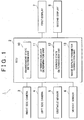
- an image providing device 1 is provided in a vehicle A and provides images of the surroundings of the vehicle A to the driver.
- the image providing device 1 realizes the improvement in image visibility by performing correction so as to reduce the difference in image display parameter such as brightness or luminance of a plurality of images provided to the driver.
- the image providing unit 1 is provided with an Electronic Control Unit (ECU) 2 that controls the entire device 1.
- the ECU 2 is an electronic control unit constituted by a Central Processing Unit (CPU), a Read Only Memory (ROM), and a Random Access Memory (RAM).
- CPU Central Processing Unit
- ROM Read Only Memory
- RAM Random Access Memory
- the application programs stored in the ROM are loaded into the RAM and executed by the CPU, thereby executing operational processing of various types relating to the process of providing images.
- the ECU 2 is connected to a right side camera 3, a left side camera 4, an obstacle sensor 5, a vehicle sensor 6, a first display 7, and a second display 8.
- the right side camera 3 is provided at a position of the right side mirror of the vehicle A.
- the right side camera 3 has an image pickup range RH extending rearward to the right of the vehicle A.
- the right side camera 3 picks up a right rear image that is an image within the image pickup range RH.
- the right side camera 3 transmits the picked-up right rear image to the ECU 2.
- the right side camera 3 functions as the first image pickup unit.
- the image pickup range RH is considered to be the first image pickup range, and the right rear image is considered to be the first image.
- the left side camera 4 is provided at a position of the left side mirror of the vehicle A.
- the left side camera 4 has an image pickup range LH extending rearward to the left of the vehicle A.
- the left side camera 4 picks up a left rear image that is an image within the image pickup range LH.
- the left side camera 4 transmits the picked-up left rear image to the ECU 2.
- the left side camera 4 functions as the second image pickup unit.
- the image pickup range LH is considered to be the second image pickup range, and the left rear image is considered to be the second image.
- the obstacle sensor 5 detects an obstacle such as a pedestrian, another vehicle, or a building present around the vehicle A.
- the obstacle sensor 5 is constituted by a plurality of sensors such as laser radar sensors and image sensors.
- the obstacle sensor 5 transmits the obstacle detection results as obstacle information to the ECU 2.
- the vehicle sensor 6 is constituted by a speed sensor, a brake sensor, a shift sensor, a steering sensor, an accelerator operation amount sensor, a headlight sensor, a wiper sensor, and the like.
- the vehicle sensor 6 detects the running state of the vehicle A by these sensors.
- the running state includes the shift state of the vehicle, the on/off state of the headlights, and the wiper drive/stop state.
- the vehicle sensor 6 transmits the detected running state of the vehicle A as running state information to the ECU 2.
- the first display 7 and the second display 8 are small displays provided, for example, side by side on the instrument panel of the vehicle A (see FIGS. 3A and 3B ).
- the first display 7 displays and provides to the driver the right rear image picked up by the right side camera 3.
- the second display 8 displays and provides to the driver the left rear image picked up by the left side camera 4. Since the first display 7 and the second display 8 are provided side by side, the driver can simultaneously recognize the state of the right rear side and left rear side of the vehicle.
- the first display 7 functions as the first image providing unit.
- the second display 8 functions as the second image providing unit.
- the ECU 2 has an environment state detection unit 10, an attention object determination unit 11, a parking state determination unit 12, and a image display parameter correction unit 13.
- the environment state detection unit 10 detects the environment state around the vehicle A on the basis of obstacle information obtained with the obstacle sensor 5 and running state information obtained with the vehicle sensor 6.
- the environment state includes an arrangement state of an obstacle such as a building or a large vehicle, a daytime or nighttime state, and a weather state.
- the environment state detection unit 10 detects, the arrangement state of an obstacle from the obstacle information obtained with the obstacle sensor 5. Further, the environment state detection unit 10 detects the daytime and nighttime state from the on/off state of the headlights and detects the weather state form the wiper drive/stop state, from among the running state information obtained with the vehicle sensor 6.
- a method for detecting the environment state is not limited to the above-described method.
- the environment state detection unit 10 may detect the present location of the vehicle A with a Global Positioning System (GPS) of the navigation system and then detect the arrangement state of buildings around the vehicle A from the map database. Further, the environment state detection unit 10 may detect the weather state including the position of sun by using weather information acquired by wireless communication.
- GPS Global Positioning System
- the attention object determination unit 11 determines an attention object to which the driver is to pay attention in the surroundings of the vehicle A on the basis of obstacle information obtained with the obstacle sensor 5.
- the attention object to which the driver is to pay attention for example, corresponds to a pedestrian or another vehicle.
- the parking state determination unit 12 determines whether or not the vehicle A is in the state before or after parking on the basis of the running state information obtained with the vehicle sensor 6.
- the state before or after parking is a state in which the vehicle A is to be parked or a state in which the vehicle is started from the parked state.
- the parking state determination unit 12 determines whether or not the vehicle A is in the state before or after parking on the basis of the vehicle speed state, vehicle steering state, and vehicle shift state, from among the vehicle state information obtained with the vehicle sensor 6. For example, the parking state determination unit 12 determines that the vehicle A is in the state before or after parking when the vehicle is in the low-speed state or the steering angle is large or when the vehicle is in the reverse shift state.
- the image display parameter correction unit 13 compares the image display parameter of the right rear image displayed by the first display 7 with the image display parameter of the left rear image displayed by the second display 8.
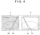
- the image display parameter correction unit 13 recognizes and compares the image display parameters in sampling ranges ER, EL shown in FIG. 4 . Since image display parameters are changed significantly by the effect of another vehicle displayed in the image within a range in which the other vehicle is seen, the ranges in which the road surface is mainly seen are selected as the sampling ranges ER, EL. Furthermore, in order to suppress more effectively the effect of the display of other vehicles and the like, the image display parameter correction unit 13 recognizes the image display parameters of the sampling ranges ER, EL by an appropriate method.
- the image display parameter correction unit 13 calculates a time average of image display parameters in the sampling ranges ER, EL and recognizes the image display parameters as the calculation results. Further, the image display parameter correction unit 13 may recognize the image display parameters within a range from which another vehicle detected by optical flow is excluded. The image display parameter correction unit 13 may also perform recognition of image display parameters from the road surface extracted by clustering. The image display parameter correction unit 13 may also perform the recognition of image display parameters by a combination of a plurality of methods.
- the image display parameter correction unit 13 changes the sampling range and the like to a mode different from the usual mode. For example, where the image display parameter correction unit 13 stores each brightness or luminance of the same lightness in the journey to the parking space, changes in the circumstances are recognized regardless of the type of road surface, and erroneous recognition of image display parameters is avoided.
- the image display parameter correction unit 13 corrects the image display parameter of the right rear image or the image display parameter of the left rear image on the basis of comparison results of the image display parameter of the right rear image and the image display parameter of the left rear image.
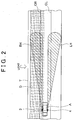
- FIG 2 shows the case where the image pickup range RH of the right side camera 3, from among the right side camera 3 and the left side camera 4, gets into a shadow D of a wall T.
- FIG. 3A shows the first display 7 and the second display 8 before the image display parameter correction in the case illustrated by FIG. 2 .
- FIG. 3B shows the first display 7 and the second display 8 after the image display parameter correction in the case illustrated by FIG 2 .
- Lane boundary lines CR, CL of the lane in which the vehicle A travels are shown in FIGS. 2 and 3 .
- the image display parameter correction unit 13 recognizes the difference in luminance caused by the shadow by comparing the image display parameter of the right rear image provided by the first display 7 and the image display parameter of the left rear image provided by the second display 8 shown in FIG. 3A . Then, as shown in FIG. 3B , the image display parameter correction unit 13 performs the correction by reducing the difference in luminance by increasing the luminance of the right rear image.
- the image display parameter correction unit 13 also corrects the image display parameter correspondingly to conditions on the basis of running state information obtained by the vehicle sensor 6, environmental conditions detected by the environment state detection unit 10, determination results obtained by the attention object determination unit 11, and determination results obtained by the parking state determination unit 12.
- the image display parameter correction unit 13 recognizes that it is daytime from the environmental conditions detected by the environment state detection unit 10, a difference in brightness or luminance often occurs when the image pickup ranges RH, LH of cameras 3, 4 get into shadow of a building or the host vehicle. Therefore, the image with a lower luminance is corrected to have a luminance identical to the luminance of the image with a higher luminance.
- the image display parameter correction unit 13. specifies the presence of an obstacle creating the shadow on the basis of arrangement conditions of the obstacle or weather conditions, from among the environmental conditions. As a result, the image display parameter correction unit 13 can distinguish between the case where the luminance is reduced by the shadow and the case where image pickup object merely has a dark color, and erroneous recognition can be avoided.
- the image display parameter correction unit 13 recognizes that it is nighttime from the environmental conditions detected by the environment state detection unit 10, the difference in brightness or luminance is often caused by the light from headlights of the trailing vehicle. Therefore, the image with a high luminance is corrected to have a luminance identical to the luminance of the image with a lower luminance. Further, where a limit threshold is set for the luminance in the image display parameter correction unit 13, bright light such as that of headlights is prevented from being directly displayed in the image.
- the parking state determination unit 12 determines that the vehicle A is in the state before or after parking, it is necessary that the image display parameter correction unit 13 accurately recognize obstacles such as surrounding walls and other vehicles. Therefore, the image with a lower luminance is corrected to have a luminance identical to the luminance of the image with a higher luminance.
- the image display parameter correction unit 13 determines whether or not an attention object is included in the right rear image or left rear image on the basis of the right rear image picked up by the right side camera 3, left rear image picked up by the left side camera 4, and determination results obtained by the attention object determination unit 11.
- the emphasizing correction as referred to herein is, for example, correction that increases brightness or luminance of the image including the attention object. Further, the emphasizing correction also includes the case where the image including the attention object is relatively emphasized by decreasing the brightness or luminance of the image that does not include the attention object.
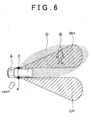
- FIG. 6 is a plan view illustrating the case in which a pedestrian B, which is an attention object, is included in the right rear image picked up by the right side camera 3.
- FIG. 7B shows the first display 7 and the second display 8 before the image display parameter correction illustrated by FIG. 6 .
- FIG. 7B shows the first display 7 and the second display 8 after the image display parameter correction illustrated by FIG. 6 .
- the image display parameter correction unit 13 determines that the pedestrian B is included in the right rear image picked up by the right side camera 3 on the basis of the right rear image picked up by the right side camera 3 shown in FIG. 7A , left rear image picked up by the left side camera 4, and determination results of the attention object determination unit 11. As shown in FIG. 7B , the image display parameter correction unit 13 performs the correction emphasizing the image by increasing the luminance with respect to the image display parameter of the right rear image that includes the pedestrian B. The image display parameter correction unit 13 also performs the correction that relatively emphasizes the right rear image by reducing the luminance of the left rear image that does not include the attention object.
- the parking state determination unit 12 determines whether the vehicle A is in the state before or after parking (S1).
- the parking state determination unit 12 determines whether the vehicle A is in the state before or after parking, for example, on the basis of vehicle speed state and vehicle steering state, from the running state information obtained by the vehicle sensor 6.
- the processing advances to step S4.
- the image display parameter correction unit 13 determines whether or not the environment state is daylight on the basis of the environment state around the vehicle that has been detected by the environment state detection unit 10 (S2). Where the image display parameter correction unit 13 has determined that the environment state is daylight, the processing advances to step S4.
- the image display parameter correction unit 13 has determined that the environment state is not daylight, it is determined that the environment state is nighttime, and the image display parameter correction unit performs a luminance reducing correction processing of correcting the image with a lower luminance to have a luminance identical to the luminance of the image with a higher luminance, from among the right rear image picked up by the right side camera 3 and the left rear image picked up by the left side camera 4 (S3). The processing then advances to step S5.
- step S4 the image display parameter correction unit 13 performs a luminance increasing correction processing of correcting the image with a higher luminance to have a luminance identical to the luminance of the image with a lower luminance from among the right rear image picked up by the right side camera 3 and the left rear image picked up by the left side camera 4.
- the processing then advances to step S5.
- the image display parameter correction unit 13 may also perform correction only in the case in which the difference in luminance between the right rear image and the left rear image is equal to or higher than a predetermined value.
- step S5 the image display parameter correction unit 13 determines whether or not an attention object is included in the right rear image or left rear image on the basis of the right rear image obtained with the right side camera 3, left rear image obtained with the left side camera 4, and determination results of the attention object determination unit 11.
- the processing returns to step S1 and the operations are repeated.
- the emphasizing correction process that emphasizes the image including the attention object is performed (S6).
- the image display parameter correction unit 13 performs the correction that increases brightness or luminance of the image including the attention object.
- the image display parameter correction unit 13 also performs the correction that relatively emphasizes the image including the attention object by decreasing the brightness or luminance of the image that does not include the attention object. The processing then returns to step S1 and the operations are repeated.
- the image display parameter of one image can be corrected so as to decrease the difference in image display parameter on the basis of results obtained in comparing the right rear image with the left rear image. Therefore, visibility of images on the left rear side and right rear side of the vehicle that are the blind zones for the driver can be improved.
- the first display 7 and the second display 8 are arranged side by side. Therefore, the driver can simultaneously recognize the left rear side and right rear side of the vehicle. Further, in this state, since visibility is greatly influenced by the difference in image display parameter, the improvement in image visibility by the image providing device 1 can be defined more clearly.
- the correction of image display parameter is performed on the basis of environment state such as daytime and nighttime, where it is daytime, the correction can be performed with reference to a brighter image correspondingly to a state in which the image abruptly becomes dark, for example, because the image pickup unit gets into shadow, and where it is nighttime, the correction can be performed with reference to a darker image correspondingly to a state in which the image abruptly becomes bright, for example, due to illumination with headlights of the trailing vehicle. Therefore, with the image providing device 1, visibility can be further improved by performing adequate correction corresponding to the environment state.
- the driver's attention can be naturally attracted to this image by performing correction that emphasizes this image, for example, by increasing the luminance, and the driver will become aware of the presence of the attention object.
- the emphasis is made using the image display parameters, and therefore the driver does not feel disturbed.
- the image display parameter correction unit 13 may also correct the image display parameter of another image with respect to the image display parameter of one image, from among the right rear image displayed by the first display 7 and the left rear image displayed by the second display 8.
- the difference in image display parameter can be reduced by correcting the image display parameter of the left rear image according to the image display parameter of the right rear image, and visibility of the image to the driver can be improved.
- the image serving as a reference for correction, from among the right rear image and left rear image can be considered the first image and the image which is to be corrected can be considered the second image.
- the image display parameter correction unit 13 may also correct both image display parameters, instead of matching the image display parameter of one image with the image display parameter of the other image, when correcting the image display parameter so as to decrease the difference in image display parameter between the right rear image arid left rear image.
- the variation amount of the image display parameter of each image can be reduced and the correction of image display parameter can be performed, without creating the feel of discomfort for the driver.
- color shade and sharpness of the image may be also included in the image parameters and correction thereof may be performed.
- the invention can be effectively applied not only to the right side camera 3 and left side camera 4, but also to a back camera that picks up images behind the vehicle. Further, the number of cameras and displays is not limited to two, and three or more cameras and displays can be also used.
- the image providing device in accordance with the invention can also implement the correction of image display parameters of various kinds according to the circumstances. For example, since the cameras easily get into shadow when the vehicle is driven in a city street, it is possible to determine whether the vehicle is driven in a city street with a navigation system and change the correction method for image display parameters. Further, the images change significantly with time when the vehicle is driven at a high speed. Therefore, it is also possible to change the correction method for image display parameters on the basis of vehicle speed.
Claims (12)
- Bildbereitstellungseinrichtung, die in einem Fahrzeug installiert ist und ein Bild einer Umgebung des Fahrzeugs an einen Fahrer bereitstellt, mit:einer ersten Bildaufnahmeeinheit (3) mit einem ersten Bildaufnahmebereich, der in der Fahrzeugumgebung positioniert ist;einer zweiten Bildaufnahmeeinheit (4) mit einem zweiten Bildaufnahmebereich, der sich mit dem ersten Bildaufnahmebereich in der Fahrzeugumgebung nicht überlappt;einer ersten Bildbereitstellungseinheit (7), die dem Fahrer ein erstes Bild bereitstellt, das ein Bild ist, das durch die erste Bildaufnahmeeinheit aufgenommen wird;einer zweiten Bildbereitstellungseinheit (8), die separat von der ersten Bildbereitstellungseinheit bereitgestellt ist und dem Fahrer ein zweites Bild bereitstellt, das ein Bild ist, das durch die zweite Bildaufnahmeeinheit aufgenommen wird; undeiner Bildanzeigeparameterkorrektureinheit (13), die zumindest einen eines Bildanzeigeparameters des ersten Bildes und eines Bildanzeigeparameters des zweiten Bildes basierend auf Vergleichsergebnissen des Bildanzeigeparameters des ersten Bildes und des Bildanzeigeparameter des zweiten Bildes korrigiert;gekennzeichnet durcheine Einheit (11) zur Bestimmung eines zu beachtenden Objekts, die bestimmt, ob ein zu beachtendes Objekt, das der Fahrer beachten soll, in dem ersten Bild oder dem zweiten Bild vorhanden ist oder nicht, wobeidie Bildanzeigeparameterkorrektureinheit (13) eine Korrektur durchführt, die von dem ersten Bild und dem zweiten Bild das Bild, von dem durch die Einheit (11) zur Bestimmung eines zu beachtenden Objekts bestimmt ist, dass es das zu beachtende Objekt enthält, hervorhebt.
- Bildbereitstellungseinrichtung gemäß Anspruch 1, wobei die Bildanzeigeparameterkorrektureinheit (13) den zweiten Bildanzeigeparameter korrigiert, so dass dieser sich dem ersten Bildanzeigeparameter annähert.
- Bildbereitstellungseinrichtung gemäß Anspruch 1, wobei die Bildanzeigeparameterkorrektureinheit (13) den ersten Bildanzeigeparameter und den zweiten Bildanzeigeparameter korrigiert, so dass eine Differenz zwischen dem ersten Bildanzeigeparameter und dem zweiten Bildanzeigeparameter reduziert wird.
- Bildbereitstellungseinrichtung gemäß einem der Ansprüche 1 bis 3, wobei die erste Bildaufnahmeeinheit (3) eine Kamera auf der rechten Seite ist, die an einer rechten vorderen Seite des Fahrzeugs bereitgestellt ist, und als das erste Bild ein Bild auf einer rechten hinteren Seite des Fahrzeugs aufnimmt, und die zweite Bildaufnahmeeinheit (4) eine Kamera auf der linken Seite ist, die an einer vorderen linken Seite des Fahrzeugs bereitgestellt ist, und als das zweite Bild ein Bild einer linken hinteren Seite des Fahrzeugs aufnimmt.
- Bildbereitstellungseinrichtung gemäß einem der Ansprüche 1 bis 4, wobei die erste Bildbereitstellungseinheit (7) und die zweite Bildbereitstellungseinheit (8) konfiguriert sind, um nebeneinander innerhalb des Fahrzeugs angeordnet zu sein.
- Bildbereitstellungseinrichtung gemäß einem der Ansprüche 1 bis 5, wobei die Bildanzeigeparameterkorrektureinheit (13) sowohl den ersten Bildanzeigeparameter als auch den zweiten Bildanzeigeparameter korrigiert.
- Bildbereitstellungseinrichtung gemäß einem der Ansprüche 1 bis 6, weiterhin mit einer Umgebungszustandserfassungseinheit (10), die einen Umgebungszustand um das Fahrzeug herum erfasst, wobei die Bildanzeigeparameterkorrektureinheit (13) den Bildanzeigeparameter basierend auf einem Erfassungsergebnis der Umgebungszustandserfassungseinheit (10) korrigiert.
- Bildbereitstellungseinrichtung gemäß Anspruch 7, weiterhin mit einem Fahrzeugsensor (6), der einen Fahrzustand des Fahrzeugs erfasst, wobei die Umgebungszustandserfassungseinheit (10) den Umgebungszustand um das Fahrzeug herum basierend auf einem Erfassungsergebnis des Fahrzeugsensors (6) erfasst.
- Bildbereitstellungseinrichtung gemäß Anspruch 7 oder 8, weiterhin mit einem Hindernissensor (5), der ein Hindernis erfasst, das um das Fahrzeug herum vorhanden ist, wobei die Umgebungszustandserfassungseinheit (10) einen Anordnungszustand des Hindernisses basierend auf Hindernisinformationen von dem Hindernissensor (5) erfasst.
- Bildbereitstellungseinrichtung gemäß einem der Ansprüche 7 bis 9, wobei die Umgebungszustandserfassungseinheit (10) einen Tag oder eine Nacht basierend auf dem ein- oder ausgeschalteten Zustand von Scheinwerfern des Fahrzeugs erfasst und einen Wetterzustand durch einen Wischeroperationszustand in dem Fahrzeug erfasst.
- Bildbereitstellungseinrichtung gemäß einem der Ansprüche 1 bis 10, wobei beim Korrigieren des ersten Bildanzeigeparameters und des zweiten Bildanzeigeparameters die Korrektur von zumindest einem einer Bildhelligkeit, einer Luminanz, eines Farbtons und einer Schärfe durchgeführt wird.
- Bildbereitstellungseinrichtung gemäß einem der Ansprüche 7 bis 11, weiterhin mit einer Parkzustandsbestimmungseinheit (12), die bestimmt, ob sich das Fahrzeug in einem Zustand vor oder nach einem Parken befindet, wobei die Parkzustandsbestimmungseinheit (12) bestimmt, ob sich das Fahrzeug in einem Zustand vor oder nach einem Parken befindet, basierend auf dem Fahrzustand, der durch den Fahrzeugsensor (6) erfasst wird.
Applications Claiming Priority (2)
| Application Number | Priority Date | Filing Date | Title |
|---|---|---|---|
| JP2010290842A JP5682304B2 (ja) | 2010-12-27 | 2010-12-27 | 画像提供装置 |
| PCT/IB2011/003099 WO2012090045A1 (en) | 2010-12-27 | 2011-12-21 | Image providing device |
Publications (2)
| Publication Number | Publication Date |
|---|---|
| EP2681078A1 EP2681078A1 (de) | 2014-01-08 |
| EP2681078B1 true EP2681078B1 (de) | 2016-03-09 |
Family
ID=45531447
Family Applications (1)
| Application Number | Title | Priority Date | Filing Date |
|---|---|---|---|
| EP11813360.2A Active EP2681078B1 (de) | 2010-12-27 | 2011-12-21 | Bildbereitstellungsvorrichtung |
Country Status (5)
| Country | Link |
|---|---|
| US (1) | US20130271608A1 (de) |
| EP (1) | EP2681078B1 (de) |
| JP (1) | JP5682304B2 (de) |
| CN (1) | CN103269908B (de) |
| WO (1) | WO2012090045A1 (de) |
Families Citing this family (16)
| Publication number | Priority date | Publication date | Assignee | Title |
|---|---|---|---|---|
| EP2879115B1 (de) | 2012-07-27 | 2018-09-05 | Nissan Motor Co., Ltd | Vorrichtung zur erfassung dreidimensionaler objekte |
| JP6413207B2 (ja) * | 2013-05-20 | 2018-10-31 | 日本精機株式会社 | 車両用表示装置 |
| GB2527510B (en) * | 2014-06-23 | 2016-12-14 | Jaguar Land Rover Ltd | Launch speed ratio selection in an automatic transmission |
| JP6600936B2 (ja) * | 2014-11-06 | 2019-11-06 | 株式会社リコー | 画像処理装置、画像処理方法、画像処理システム、プログラム、及び記録媒体 |
| JP6485899B2 (ja) * | 2014-12-08 | 2019-03-20 | ソニー・オリンパスメディカルソリューションズ株式会社 | 医療用立体観察装置、医療用立体観察方法、及びプログラム |
| JP6393653B2 (ja) * | 2015-04-09 | 2018-09-19 | 株式会社東海理化電機製作所 | 車両用視認装置 |
| JP6750519B2 (ja) * | 2016-05-24 | 2020-09-02 | 株式会社Jvcケンウッド | 撮像装置、撮像表示方法および撮像表示プログラム |
| JP6855235B2 (ja) * | 2016-12-16 | 2021-04-07 | 日産自動車株式会社 | 自動車用運転操作装置及び自動車用運転操作方法 |
| JP6740916B2 (ja) * | 2017-01-23 | 2020-08-19 | 株式会社デンソー | 運転支援システム、運転支援方法 |
| CN107133597A (zh) * | 2017-05-11 | 2017-09-05 | 南宁市正祥科技有限公司 | 一种日间前方车辆检测方法 |
| JP6879132B2 (ja) * | 2017-08-31 | 2021-06-02 | 日本精機株式会社 | 電子ミラー表示装置、車両用表示システム |
| CN111699680B (zh) * | 2018-03-15 | 2022-03-01 | Jvc建伍株式会社 | 行车记录仪、显示控制方法以及存储介质 |
| FR3079790A1 (fr) * | 2018-04-06 | 2019-10-11 | Psa Automobiles Sa | Dispositif de retrovision pour un vehicule |
| KR20200005282A (ko) * | 2018-07-06 | 2020-01-15 | 현대모비스 주식회사 | 미러리스 자동차의 측방 영상 처리 장치 및 방법 |
| JP2020104804A (ja) * | 2018-12-28 | 2020-07-09 | トヨタ自動車株式会社 | 電子ミラーシステム |
| JP7321987B2 (ja) * | 2020-10-01 | 2023-08-07 | ダイハツ工業株式会社 | 車両用複眼カメラ |
Family Cites Families (15)
| Publication number | Priority date | Publication date | Assignee | Title |
|---|---|---|---|---|
| US6891563B2 (en) * | 1996-05-22 | 2005-05-10 | Donnelly Corporation | Vehicular vision system |
| US5982951A (en) * | 1996-05-28 | 1999-11-09 | Canon Kabushiki Kaisha | Apparatus and method for combining a plurality of images |
| EP1044116A2 (de) * | 1997-12-31 | 2000-10-18 | Gentex Corporation | Sichtsystem für kraftfahrzeug |
| JP3297040B1 (ja) * | 2001-04-24 | 2002-07-02 | 松下電器産業株式会社 | 車載カメラの画像合成表示方法及びその装置 |
| JP2004173048A (ja) * | 2002-11-21 | 2004-06-17 | Auto Network Gijutsu Kenkyusho:Kk | 車載カメラシステム |
| JP4251099B2 (ja) * | 2004-03-25 | 2009-04-08 | 三菱自動車工業株式会社 | 車両用周辺確認装置 |
| JP4134939B2 (ja) * | 2004-04-22 | 2008-08-20 | 株式会社デンソー | 車両周辺表示制御装置 |
| JP4706466B2 (ja) * | 2005-12-16 | 2011-06-22 | 株式会社日立製作所 | 撮像装置 |
| JP4325642B2 (ja) * | 2006-05-31 | 2009-09-02 | ソニー株式会社 | 移動体カメラシステム |
| JP4985169B2 (ja) * | 2007-07-13 | 2012-07-25 | トヨタ自動車株式会社 | カメラネットワークシステム、表示装置、カメラ |
| JP2009040107A (ja) * | 2007-08-06 | 2009-02-26 | Denso Corp | 画像表示制御装置及び画像表示制御システム |
| JP4941760B2 (ja) * | 2007-09-24 | 2012-05-30 | 株式会社デンソー | 車両周辺監視装置 |
| JP2009083618A (ja) * | 2007-09-28 | 2009-04-23 | Panasonic Corp | 電子ミラーシステム |
| US20100057465A1 (en) * | 2008-09-03 | 2010-03-04 | David Michael Kirsch | Variable text-to-speech for automotive application |
| US8521367B2 (en) * | 2008-09-30 | 2013-08-27 | Nissan Motor Co., Ltd. | System provided with an assistance-controller for assisting an operator of the system, control-operation assisting device, control-operation assisting method, driving-operation assisting device, and driving-operation assisting method |
-
2010
- 2010-12-27 JP JP2010290842A patent/JP5682304B2/ja active Active
-
2011
- 2011-12-21 EP EP11813360.2A patent/EP2681078B1/de active Active
- 2011-12-21 WO PCT/IB2011/003099 patent/WO2012090045A1/en active Application Filing
- 2011-12-21 US US13/996,235 patent/US20130271608A1/en not_active Abandoned
- 2011-12-21 CN CN201180062576.5A patent/CN103269908B/zh active Active
Also Published As
| Publication number | Publication date |
|---|---|
| EP2681078A1 (de) | 2014-01-08 |
| CN103269908A (zh) | 2013-08-28 |
| WO2012090045A1 (en) | 2012-07-05 |
| CN103269908B (zh) | 2016-11-23 |
| JP2012138828A (ja) | 2012-07-19 |
| US20130271608A1 (en) | 2013-10-17 |
| JP5682304B2 (ja) | 2015-03-11 |
Similar Documents
| Publication | Publication Date | Title |
|---|---|---|
| EP2681078B1 (de) | Bildbereitstellungsvorrichtung | |
| US11565690B2 (en) | Vehicular driving assistance system that controls a vehicle in accordance with parameters preferred by an identified driver | |
| EP3127771B1 (de) | Fahrerassistenzvorrichtung und fahrzeug damit | |
| US9538144B2 (en) | Full speed lane sensing using multiple cameras | |
| JP5022609B2 (ja) | 撮像環境認識装置 | |
| JP5680573B2 (ja) | 車両の走行環境認識装置 | |
| JP4937199B2 (ja) | オートライト装置 | |
| EP2487906B1 (de) | Steuervorrichtung und umgebungsüberwachungsvorrichtung für ein fahrzeug | |
| JP5276637B2 (ja) | 車線推定装置 | |
| JP5399027B2 (ja) | 自動車の運転を支援するための、立体画像を捕捉することができるシステムを有するデバイス | |
| EP1035455A1 (de) | Rückraumüberwachungssystem | |
| JP2008250904A (ja) | 車線区分線情報検出装置、走行車線維持装置、車線区分線認識方法 | |
| JP2008222153A (ja) | 合流支援装置 | |
| US20150016678A1 (en) | Apparatus and method of predicting turns of vehicle | |
| JP2010188826A (ja) | 車両用表示装置 | |
| JP6330296B2 (ja) | 走行支援装置及び走行支援方法 | |
| CN113327201A (zh) | 图像处理装置及图像处理方法 | |
| CN116419072A (zh) | 车辆摄像头动态 | |
| JP2009147906A (ja) | 車両周辺監視装置 | |
| EP3763578A1 (de) | Fahrzeugausrüstungssteuerung | |
| JP7116670B2 (ja) | 走行制御装置、制御方法およびプログラム | |
| US10668856B2 (en) | Display control device for vehicle, display control system for vehicle, display control method for vehicle | |
| US20230222813A1 (en) | Road surface marking detection device, notification system provided with the same, and road surface marking detection | |
| CN117125091A (zh) | 一种基于感知的智能驾驶辅助方法及装置 | |
| JP2023111474A (ja) | 車両制御装置 |
Legal Events
| Date | Code | Title | Description |
|---|---|---|---|
| PUAI | Public reference made under article 153(3) epc to a published international application that has entered the european phase |
Free format text: ORIGINAL CODE: 0009012 |
|
| 17P | Request for examination filed |
Effective date: 20130624 |
|
| AK | Designated contracting states |
Kind code of ref document: A1 Designated state(s): AL AT BE BG CH CY CZ DE DK EE ES FI FR GB GR HR HU IE IS IT LI LT LU LV MC MK MT NL NO PL PT RO RS SE SI SK SM TR |
|
| DAX | Request for extension of the european patent (deleted) | ||
| 17Q | First examination report despatched |
Effective date: 20141111 |
|
| GRAP | Despatch of communication of intention to grant a patent |
Free format text: ORIGINAL CODE: EPIDOSNIGR1 |
|
| INTG | Intention to grant announced |
Effective date: 20150827 |
|
| GRAS | Grant fee paid |
Free format text: ORIGINAL CODE: EPIDOSNIGR3 |
|
| GRAA | (expected) grant |
Free format text: ORIGINAL CODE: 0009210 |
|
| AK | Designated contracting states |
Kind code of ref document: B1 Designated state(s): AL AT BE BG CH CY CZ DE DK EE ES FI FR GB GR HR HU IE IS IT LI LT LU LV MC MK MT NL NO PL PT RO RS SE SI SK SM TR |
|
| REG | Reference to a national code |
Ref country code: GB Ref legal event code: FG4D |
|
| REG | Reference to a national code |
Ref country code: AT Ref legal event code: REF Ref document number: 779228 Country of ref document: AT Kind code of ref document: T Effective date: 20160315 Ref country code: CH Ref legal event code: EP |
|
| REG | Reference to a national code |
Ref country code: IE Ref legal event code: FG4D |
|
| REG | Reference to a national code |
Ref country code: DE Ref legal event code: R096 Ref document number: 602011023902 Country of ref document: DE |
|
| REG | Reference to a national code |
Ref country code: LT Ref legal event code: MG4D |
|
| REG | Reference to a national code |
Ref country code: NL Ref legal event code: MP Effective date: 20160309 |
|
| PG25 | Lapsed in a contracting state [announced via postgrant information from national office to epo] |
Ref country code: ES Free format text: LAPSE BECAUSE OF FAILURE TO SUBMIT A TRANSLATION OF THE DESCRIPTION OR TO PAY THE FEE WITHIN THE PRESCRIBED TIME-LIMIT Effective date: 20160309 Ref country code: GR Free format text: LAPSE BECAUSE OF FAILURE TO SUBMIT A TRANSLATION OF THE DESCRIPTION OR TO PAY THE FEE WITHIN THE PRESCRIBED TIME-LIMIT Effective date: 20160610 Ref country code: HR Free format text: LAPSE BECAUSE OF FAILURE TO SUBMIT A TRANSLATION OF THE DESCRIPTION OR TO PAY THE FEE WITHIN THE PRESCRIBED TIME-LIMIT Effective date: 20160309 Ref country code: FI Free format text: LAPSE BECAUSE OF FAILURE TO SUBMIT A TRANSLATION OF THE DESCRIPTION OR TO PAY THE FEE WITHIN THE PRESCRIBED TIME-LIMIT Effective date: 20160309 Ref country code: NO Free format text: LAPSE BECAUSE OF FAILURE TO SUBMIT A TRANSLATION OF THE DESCRIPTION OR TO PAY THE FEE WITHIN THE PRESCRIBED TIME-LIMIT Effective date: 20160609 |
|
| REG | Reference to a national code |
Ref country code: AT Ref legal event code: MK05 Ref document number: 779228 Country of ref document: AT Kind code of ref document: T Effective date: 20160309 |
|
| PG25 | Lapsed in a contracting state [announced via postgrant information from national office to epo] |
Ref country code: LV Free format text: LAPSE BECAUSE OF FAILURE TO SUBMIT A TRANSLATION OF THE DESCRIPTION OR TO PAY THE FEE WITHIN THE PRESCRIBED TIME-LIMIT Effective date: 20160309 Ref country code: SE Free format text: LAPSE BECAUSE OF FAILURE TO SUBMIT A TRANSLATION OF THE DESCRIPTION OR TO PAY THE FEE WITHIN THE PRESCRIBED TIME-LIMIT Effective date: 20160309 Ref country code: RS Free format text: LAPSE BECAUSE OF FAILURE TO SUBMIT A TRANSLATION OF THE DESCRIPTION OR TO PAY THE FEE WITHIN THE PRESCRIBED TIME-LIMIT Effective date: 20160309 Ref country code: NL Free format text: LAPSE BECAUSE OF FAILURE TO SUBMIT A TRANSLATION OF THE DESCRIPTION OR TO PAY THE FEE WITHIN THE PRESCRIBED TIME-LIMIT Effective date: 20160309 Ref country code: LT Free format text: LAPSE BECAUSE OF FAILURE TO SUBMIT A TRANSLATION OF THE DESCRIPTION OR TO PAY THE FEE WITHIN THE PRESCRIBED TIME-LIMIT Effective date: 20160309 Ref country code: PL Free format text: LAPSE BECAUSE OF FAILURE TO SUBMIT A TRANSLATION OF THE DESCRIPTION OR TO PAY THE FEE WITHIN THE PRESCRIBED TIME-LIMIT Effective date: 20160309 |
|
| REG | Reference to a national code |
Ref country code: DE Ref legal event code: R084 Ref document number: 602011023902 Country of ref document: DE |
|
| PG25 | Lapsed in a contracting state [announced via postgrant information from national office to epo] |
Ref country code: EE Free format text: LAPSE BECAUSE OF FAILURE TO SUBMIT A TRANSLATION OF THE DESCRIPTION OR TO PAY THE FEE WITHIN THE PRESCRIBED TIME-LIMIT Effective date: 20160309 Ref country code: IS Free format text: LAPSE BECAUSE OF FAILURE TO SUBMIT A TRANSLATION OF THE DESCRIPTION OR TO PAY THE FEE WITHIN THE PRESCRIBED TIME-LIMIT Effective date: 20160709 |
|
| PG25 | Lapsed in a contracting state [announced via postgrant information from national office to epo] |
Ref country code: PT Free format text: LAPSE BECAUSE OF FAILURE TO SUBMIT A TRANSLATION OF THE DESCRIPTION OR TO PAY THE FEE WITHIN THE PRESCRIBED TIME-LIMIT Effective date: 20160711 Ref country code: CZ Free format text: LAPSE BECAUSE OF FAILURE TO SUBMIT A TRANSLATION OF THE DESCRIPTION OR TO PAY THE FEE WITHIN THE PRESCRIBED TIME-LIMIT Effective date: 20160309 Ref country code: RO Free format text: LAPSE BECAUSE OF FAILURE TO SUBMIT A TRANSLATION OF THE DESCRIPTION OR TO PAY THE FEE WITHIN THE PRESCRIBED TIME-LIMIT Effective date: 20160309 Ref country code: AT Free format text: LAPSE BECAUSE OF FAILURE TO SUBMIT A TRANSLATION OF THE DESCRIPTION OR TO PAY THE FEE WITHIN THE PRESCRIBED TIME-LIMIT Effective date: 20160309 Ref country code: SK Free format text: LAPSE BECAUSE OF FAILURE TO SUBMIT A TRANSLATION OF THE DESCRIPTION OR TO PAY THE FEE WITHIN THE PRESCRIBED TIME-LIMIT Effective date: 20160309 Ref country code: SM Free format text: LAPSE BECAUSE OF FAILURE TO SUBMIT A TRANSLATION OF THE DESCRIPTION OR TO PAY THE FEE WITHIN THE PRESCRIBED TIME-LIMIT Effective date: 20160309 |
|
| REG | Reference to a national code |
Ref country code: DE Ref legal event code: R097 Ref document number: 602011023902 Country of ref document: DE |
|
| PG25 | Lapsed in a contracting state [announced via postgrant information from national office to epo] |
Ref country code: IT Free format text: LAPSE BECAUSE OF FAILURE TO SUBMIT A TRANSLATION OF THE DESCRIPTION OR TO PAY THE FEE WITHIN THE PRESCRIBED TIME-LIMIT Effective date: 20160309 Ref country code: BE Free format text: LAPSE BECAUSE OF FAILURE TO SUBMIT A TRANSLATION OF THE DESCRIPTION OR TO PAY THE FEE WITHIN THE PRESCRIBED TIME-LIMIT Effective date: 20160309 |
|
| PLBE | No opposition filed within time limit |
Free format text: ORIGINAL CODE: 0009261 |
|
| STAA | Information on the status of an ep patent application or granted ep patent |
Free format text: STATUS: NO OPPOSITION FILED WITHIN TIME LIMIT |
|
| PG25 | Lapsed in a contracting state [announced via postgrant information from national office to epo] |
Ref country code: DK Free format text: LAPSE BECAUSE OF FAILURE TO SUBMIT A TRANSLATION OF THE DESCRIPTION OR TO PAY THE FEE WITHIN THE PRESCRIBED TIME-LIMIT Effective date: 20160309 |
|
| 26N | No opposition filed |
Effective date: 20161212 |
|
| PG25 | Lapsed in a contracting state [announced via postgrant information from national office to epo] |
Ref country code: BG Free format text: LAPSE BECAUSE OF FAILURE TO SUBMIT A TRANSLATION OF THE DESCRIPTION OR TO PAY THE FEE WITHIN THE PRESCRIBED TIME-LIMIT Effective date: 20160609 |
|
| PG25 | Lapsed in a contracting state [announced via postgrant information from national office to epo] |
Ref country code: SI Free format text: LAPSE BECAUSE OF FAILURE TO SUBMIT A TRANSLATION OF THE DESCRIPTION OR TO PAY THE FEE WITHIN THE PRESCRIBED TIME-LIMIT Effective date: 20160309 |
|
| REG | Reference to a national code |
Ref country code: CH Ref legal event code: PL |
|
| GBPC | Gb: european patent ceased through non-payment of renewal fee |
Effective date: 20161221 |
|
| PG25 | Lapsed in a contracting state [announced via postgrant information from national office to epo] |
Ref country code: MC Free format text: LAPSE BECAUSE OF FAILURE TO SUBMIT A TRANSLATION OF THE DESCRIPTION OR TO PAY THE FEE WITHIN THE PRESCRIBED TIME-LIMIT Effective date: 20160309 |
|
| REG | Reference to a national code |
Ref country code: FR Ref legal event code: ST Effective date: 20170831 |
|
| REG | Reference to a national code |
Ref country code: IE Ref legal event code: MM4A |
|
| PG25 | Lapsed in a contracting state [announced via postgrant information from national office to epo] |
Ref country code: LU Free format text: LAPSE BECAUSE OF NON-PAYMENT OF DUE FEES Effective date: 20161221 Ref country code: FR Free format text: LAPSE BECAUSE OF NON-PAYMENT OF DUE FEES Effective date: 20170102 Ref country code: LI Free format text: LAPSE BECAUSE OF NON-PAYMENT OF DUE FEES Effective date: 20161231 Ref country code: CH Free format text: LAPSE BECAUSE OF NON-PAYMENT OF DUE FEES Effective date: 20161231 |
|
| PG25 | Lapsed in a contracting state [announced via postgrant information from national office to epo] |
Ref country code: IE Free format text: LAPSE BECAUSE OF NON-PAYMENT OF DUE FEES Effective date: 20161221 Ref country code: GB Free format text: LAPSE BECAUSE OF NON-PAYMENT OF DUE FEES Effective date: 20161221 |
|
| PG25 | Lapsed in a contracting state [announced via postgrant information from national office to epo] |
Ref country code: HU Free format text: LAPSE BECAUSE OF FAILURE TO SUBMIT A TRANSLATION OF THE DESCRIPTION OR TO PAY THE FEE WITHIN THE PRESCRIBED TIME-LIMIT; INVALID AB INITIO Effective date: 20111221 Ref country code: CY Free format text: LAPSE BECAUSE OF FAILURE TO SUBMIT A TRANSLATION OF THE DESCRIPTION OR TO PAY THE FEE WITHIN THE PRESCRIBED TIME-LIMIT Effective date: 20160309 |
|
| PG25 | Lapsed in a contracting state [announced via postgrant information from national office to epo] |
Ref country code: MK Free format text: LAPSE BECAUSE OF FAILURE TO SUBMIT A TRANSLATION OF THE DESCRIPTION OR TO PAY THE FEE WITHIN THE PRESCRIBED TIME-LIMIT Effective date: 20160309 |
|
| PG25 | Lapsed in a contracting state [announced via postgrant information from national office to epo] |
Ref country code: MT Free format text: LAPSE BECAUSE OF NON-PAYMENT OF DUE FEES Effective date: 20161221 |
|
| PG25 | Lapsed in a contracting state [announced via postgrant information from national office to epo] |
Ref country code: AL Free format text: LAPSE BECAUSE OF FAILURE TO SUBMIT A TRANSLATION OF THE DESCRIPTION OR TO PAY THE FEE WITHIN THE PRESCRIBED TIME-LIMIT Effective date: 20160309 Ref country code: TR Free format text: LAPSE BECAUSE OF FAILURE TO SUBMIT A TRANSLATION OF THE DESCRIPTION OR TO PAY THE FEE WITHIN THE PRESCRIBED TIME-LIMIT Effective date: 20160309 |
|
| P01 | Opt-out of the competence of the unified patent court (upc) registered |
Effective date: 20230427 |
|
| PGFP | Annual fee paid to national office [announced via postgrant information from national office to epo] |
Ref country code: DE Payment date: 20231031 Year of fee payment: 13 |