EP2677104B1 - Sicherheitsschrank - Google Patents
Sicherheitsschrank Download PDFInfo
- Publication number
- EP2677104B1 EP2677104B1 EP13167656.1A EP13167656A EP2677104B1 EP 2677104 B1 EP2677104 B1 EP 2677104B1 EP 13167656 A EP13167656 A EP 13167656A EP 2677104 B1 EP2677104 B1 EP 2677104B1
- Authority
- EP
- European Patent Office
- Prior art keywords
- connecting element
- swing door
- door
- swing
- closing
- Prior art date
- Legal status (The legal status is an assumption and is not a legal conclusion. Google has not performed a legal analysis and makes no representation as to the accuracy of the status listed.)
- Active
Links
- 239000000383 hazardous chemical Substances 0.000 claims description 5
- 238000000034 method Methods 0.000 description 4
- 230000008569 process Effects 0.000 description 3
- 230000007704 transition Effects 0.000 description 3
- 238000010276 construction Methods 0.000 description 2
- RNFJDJUURJAICM-UHFFFAOYSA-N 2,2,4,4,6,6-hexaphenoxy-1,3,5-triaza-2$l^{5},4$l^{5},6$l^{5}-triphosphacyclohexa-1,3,5-triene Chemical compound N=1P(OC=2C=CC=CC=2)(OC=2C=CC=CC=2)=NP(OC=2C=CC=CC=2)(OC=2C=CC=CC=2)=NP=1(OC=1C=CC=CC=1)OC1=CC=CC=C1 RNFJDJUURJAICM-UHFFFAOYSA-N 0.000 description 1
- 230000009471 action Effects 0.000 description 1
- 238000005452 bending Methods 0.000 description 1
- 230000008878 coupling Effects 0.000 description 1
- 238000010168 coupling process Methods 0.000 description 1
- 238000005859 coupling reaction Methods 0.000 description 1
- 238000006073 displacement reaction Methods 0.000 description 1
- 239000003063 flame retardant Substances 0.000 description 1
- 231100001261 hazardous Toxicity 0.000 description 1
- 230000006872 improvement Effects 0.000 description 1
- 239000007788 liquid Substances 0.000 description 1
- 239000000463 material Substances 0.000 description 1
- 239000002184 metal Substances 0.000 description 1
- 239000000126 substance Substances 0.000 description 1
- 230000001360 synchronised effect Effects 0.000 description 1
Images

Classifications
-
- E—FIXED CONSTRUCTIONS
- E05—LOCKS; KEYS; WINDOW OR DOOR FITTINGS; SAFES
- E05F—DEVICES FOR MOVING WINGS INTO OPEN OR CLOSED POSITION; CHECKS FOR WINGS; WING FITTINGS NOT OTHERWISE PROVIDED FOR, CONCERNED WITH THE FUNCTIONING OF THE WING
- E05F1/00—Closers or openers for wings, not otherwise provided for in this subclass
- E05F1/08—Closers or openers for wings, not otherwise provided for in this subclass spring-actuated, e.g. for horizontally sliding wings
- E05F1/10—Closers or openers for wings, not otherwise provided for in this subclass spring-actuated, e.g. for horizontally sliding wings for swinging wings, e.g. counterbalance
-
- E—FIXED CONSTRUCTIONS
- E05—LOCKS; KEYS; WINDOW OR DOOR FITTINGS; SAFES
- E05F—DEVICES FOR MOVING WINGS INTO OPEN OR CLOSED POSITION; CHECKS FOR WINGS; WING FITTINGS NOT OTHERWISE PROVIDED FOR, CONCERNED WITH THE FUNCTIONING OF THE WING
- E05F17/00—Special devices for shifting a plurality of wings operated simultaneously
- E05F17/004—Special devices for shifting a plurality of wings operated simultaneously for wings which abut when closed
-
- E—FIXED CONSTRUCTIONS
- E05—LOCKS; KEYS; WINDOW OR DOOR FITTINGS; SAFES
- E05G—SAFES OR STRONG-ROOMS FOR VALUABLES; BANK PROTECTION DEVICES; SAFETY TRANSACTION PARTITIONS
- E05G1/00—Safes or strong-rooms for valuables
-
- E—FIXED CONSTRUCTIONS
- E05—LOCKS; KEYS; WINDOW OR DOOR FITTINGS; SAFES
- E05G—SAFES OR STRONG-ROOMS FOR VALUABLES; BANK PROTECTION DEVICES; SAFETY TRANSACTION PARTITIONS
- E05G1/00—Safes or strong-rooms for valuables
- E05G1/02—Details
- E05G1/026—Closures
-
- E—FIXED CONSTRUCTIONS
- E05—LOCKS; KEYS; WINDOW OR DOOR FITTINGS; SAFES
- E05F—DEVICES FOR MOVING WINGS INTO OPEN OR CLOSED POSITION; CHECKS FOR WINGS; WING FITTINGS NOT OTHERWISE PROVIDED FOR, CONCERNED WITH THE FUNCTIONING OF THE WING
- E05F1/00—Closers or openers for wings, not otherwise provided for in this subclass
- E05F1/002—Closers or openers for wings, not otherwise provided for in this subclass controlled by automatically acting means
- E05F1/006—Closers or openers for wings, not otherwise provided for in this subclass controlled by automatically acting means by emergency conditions, e.g. fire
-
- E—FIXED CONSTRUCTIONS
- E05—LOCKS; KEYS; WINDOW OR DOOR FITTINGS; SAFES
- E05F—DEVICES FOR MOVING WINGS INTO OPEN OR CLOSED POSITION; CHECKS FOR WINGS; WING FITTINGS NOT OTHERWISE PROVIDED FOR, CONCERNED WITH THE FUNCTIONING OF THE WING
- E05F1/00—Closers or openers for wings, not otherwise provided for in this subclass
- E05F1/08—Closers or openers for wings, not otherwise provided for in this subclass spring-actuated, e.g. for horizontally sliding wings
- E05F1/10—Closers or openers for wings, not otherwise provided for in this subclass spring-actuated, e.g. for horizontally sliding wings for swinging wings, e.g. counterbalance
- E05F1/1041—Closers or openers for wings, not otherwise provided for in this subclass spring-actuated, e.g. for horizontally sliding wings for swinging wings, e.g. counterbalance with a coil spring perpendicular to the pivot axis
-
- E—FIXED CONSTRUCTIONS
- E05—LOCKS; KEYS; WINDOW OR DOOR FITTINGS; SAFES
- E05F—DEVICES FOR MOVING WINGS INTO OPEN OR CLOSED POSITION; CHECKS FOR WINGS; WING FITTINGS NOT OTHERWISE PROVIDED FOR, CONCERNED WITH THE FUNCTIONING OF THE WING
- E05F17/00—Special devices for shifting a plurality of wings operated simultaneously
- E05F2017/008—Special devices for shifting a plurality of wings operated simultaneously for swinging wings
-
- E—FIXED CONSTRUCTIONS
- E05—LOCKS; KEYS; WINDOW OR DOOR FITTINGS; SAFES
- E05Y—INDEXING SCHEME ASSOCIATED WITH SUBCLASSES E05D AND E05F, RELATING TO CONSTRUCTION ELEMENTS, ELECTRIC CONTROL, POWER SUPPLY, POWER SIGNAL OR TRANSMISSION, USER INTERFACES, MOUNTING OR COUPLING, DETAILS, ACCESSORIES, AUXILIARY OPERATIONS NOT OTHERWISE PROVIDED FOR, APPLICATION THEREOF
- E05Y2900/00—Application of doors, windows, wings or fittings thereof
- E05Y2900/20—Application of doors, windows, wings or fittings thereof for furniture, e.g. cabinets
- E05Y2900/21—Application of doors, windows, wings or fittings thereof for furniture, e.g. cabinets for safety cabinets
Definitions
- the invention relates to a safety cabinet, in particular Hazardous goods cabinet, with at least two jointly connected to a slidable in a guide connecting pivot doors, the respective swing door is rotatably connected to the cabinet body via a respective edge side a cabinet body arranged axis of rotation, and wherein the respective swing door of the two swing doors is connected by means of a respective own hinge assembly to the connecting element, and with a spring unit, which acts on both swing doors, at least in the closing operation in the direction of its closed position, wherein the closing operation, the connecting element is moved from its open position to a closed position along the guide.
- Safety cabinets and in particular hazardous substance cabinets are typically used for storing mostly flammable hazardous substances such as chemicals, flammable liquids, etc.
- flammable hazardous substances such as chemicals, flammable liquids, etc.
- the security cabinet in question is reliably closed in the closed operation. This is ensured by the spring unit, which ensures in automatic closing operation or in the event of a fire that the two swing doors are reliably and automatically closed.
- a manual and / or motor - and not automatic - opening and closing is provided in normal operation.
- the connecting element can be moved in a guide. This allows the swing doors to open and close synchronously.
- Comparable is in the safety cabinet according to the EP 2 017 420 A1 proceed. Also in this case, two swing doors are connected together to a displaceable in a guide connecting element. At least during closing operation, the spring unit ensures that both swing doors are subjected to a force in the direction of their closed position. In this case, the spring unit is functionally decoupled from the connecting element in normal operation and acted upon this only in the closing operation. In this way, a reliable function of the spring unit is ensured in the closing operation under all circumstances.
- EP 2 221 438 A2 also deals with a safety cabinet in which the spring unit in normal operation, that is, during (manually) caused opening and closing movements of the swing doors, constantly maintains its cocked position.
- the spring unit has a driver, which interacts with the swing doors only in the closing operation, for example in case of fire.
- the swing doors can also be connected in each case to a separate connection element in the course of a two-handed operation in normal operation.
- the swing doors already operate independently, are still closed together with the help of the spring unit in the closing operation.
- the design chosen at this point is technologically relatively complicated and thus in need of improvement.
- the invention is based on the technical problem of further developing a safety cabinet of the construction described above, that with perfect functionality and in particular while maintaining the ability to individually apply the respective swing door in normal operation, nevertheless a safe closing operation with a structurally simple construction for Is made available.
- a safety cabinet according to claim 1 is provided.
- the opening or closing movement of the rotary door in question is accomplished manually and / or motorically in normal operation.
- a manual operation and a manual operation of the swing door in normal operation in question it is ensured in each case that the other rotary door is mechanically decoupled from the connecting element in the normal operation in comparison with the manually applied rotary door.
- a (single) connecting element is used, from which the other rotary door in question is mechanically decoupled in the procedure described.
- the respective swing door of the two swing doors is connected by means of a respective own hinge assembly to the connecting element.
- the joint arrangement is essentially composed of a connecting joint arm which is rotatably coupled to the (single) connecting element and, in addition, a door joint arm rotatably connected to the revolving wing door. That is, the joint assembly for connecting the respective swing door to the connecting element is usually designed in two parts and consists of the already mentioned connecting joint arm and the Mosgelenkarm together.
- Both articulated arms are also connected to each other articulated.
- the connecting joint arm is pivotally connected to the connecting element.
- the Schogelenkarm which forms a pivotal connection with the swing door.
- the articulated arrangement of the rotary wing door acted upon in the course of the opening movement bears against the stop of the connecting element in normal operation.
- two stops are provided on the connecting element for the respective joint arrangement.
- the attacks are according to the invention to door-side stops, that is, stops that are connected to the connecting element in the direction of the swing door.
- the connecting element is usually formed (mirror) symmetrically in comparison to the central guide.
- the stops are arranged substantially at right angles compared to a connection plate. In this case, the terminal plate and the two door-side stops can be made practically in one go become.
- the connecting element has the connection plate in question, which is generally equipped with pivot axes for the rotatable connection of the respective joint arrangement. It has further proven, if the attacks in question include an obtuse angle between them.
- the overall interpretation is such that the hinge assembly door with the connecting element in each case coupling joint arrangement rests in the open position of the respective swing door to the associated door-side stop of the connecting element.
- the closed position of the swing door generally corresponds to the fact that the hinge assembly in this case protrudes angularly from the door-side stop in question.
- the design is made such that the joint arrangement of in the course of the opening or closing movement (in normal operation) acted upon rotary door is adjusted relative to the connecting element. That is, the normal operation corresponds to the connecting member maintaining its open position.
- This opening position of the connecting element (in normal operation) belongs to a door-side end position in comparison to the associated guide. In other words, the connecting element is in the open position (in normal operation) in the immediate vicinity of the (closed) swing door - as it were vis-à-vis.
- This opening position assumes the connecting element in normal operation throughout. If the connecting element is moved into the closed position along the guide, the closing operation, for example a fire, corresponds thereto. In the closing operation, the connecting element is moved from its open position to the closed position along the guide. in this connection at the same time one or both swing doors are closed, provided that they are open.
- the closed position of the connecting element and thus the closing operation corresponds, for example in case of fire to an approximately central position of the connecting element in comparison to the already mentioned guide.
- the longitudinal extension of the guide in question follows the opening / closing direction of the connecting element.
- the connecting element is transverse to the guide extends.
- the opening position of the connecting element belongs to the door-side end position in comparison to the guide.
- the respective swing door can be acted upon individually and independently of the other swing door, for example, manually, in normal operation.
- an opening operation of the relevant swing door in this normal operation corresponds to the fact that the joint arrangement is moved relative to the connecting element.
- the hinge assembly performs an angular movement away from the respective stop of the connecting element.
- the connecting element remains at rest. This also applies to the other swing door, which is mechanically decoupled from the connecting element in question.
- the connecting element remains in its open position during normal operation until the spring unit is activated. In fact, the connecting element is fixed in its open position and its door-side end position. Only in the closing operation, this fixation is canceled. In the event of fire, a thermally dissolved fusible link may cause this. In this way, the spring unit can now move the connecting element in its closed position along the guide.
- the associated swing door is applied closing as soon as the connecting element is transferred from its open position to the closed position by means of the spring unit. This ensures that the safety cabinet according to the invention is closed in the closing operation in any case is and the inside of hazardous materials safe storage in the event of fire.
- the main benefits are the main benefits.
- a safety cabinet and in particular hazardous materials cabinet which has a cabinet body 1, are connected to the swing doors 2.
- the respective swing door 2 is connected via a respective edge of the cabinet body 1 arranged axis of rotation 3 to the cabinet body 1.
- Both the cabinet body 1 and the associated swing door 2 have an inner lining 4, 5, which may be constructed of non-flammable or flame-retardant material plates. It can be seen that in the present case two swing doors 2 are realized, which are connected together to a displaceable in a guide 6 connecting element 7.
- the connecting element 7 is substantially axially symmetrical in comparison to the central guide 6.
- the connecting member 7 extends substantially transversely compared to the longitudinal extent of the guide 6.
- the guide 6 is formed and arranged so that they are along a by an arrow in the Fig. 2 indicated closing movement of the associated Swing door 2 and the connecting element 7 extends.
- the connecting element 7 may engage with a roller assembly, a web, a sword or the like in the embodiment equipped with two rails with a central recess guide 6.
- the connecting element 7 undergoes a linear displacement along the guide 6 as soon as the connecting element 7 moves from its opening position, which is normally assumed during normal operation, in the door-side end position relative to the guide 6 Fig. 2 in the closed position with a central arrangement relative to the guide 6 according to Fig. 1 is transferred.
- the closed position of the connecting element 7 after Fig. 1 corresponds to the closing operation, for example to a fire.
- the respective swing door 2 is connected by means of a hinge arrangement 8, 9 to the connecting element 7.
- the joint arrangement 8, 9 essentially consists of a connection joint arm 8 which is rotatably coupled to the connection element 7 and a door joint arm 9 rotatably connected to the associated swing door 2.
- the connecting joint arm 8 and the Schogelenkarm 9 are in turn hinged together.
- connection plate 11 in question and the associated stops 10 can be produced in a particularly simple and cost-effective manner, namely by means of customary metal stamping / bending processes.
- connection plate 11 is equipped with axes of rotation 12, by means of which the respective joint arrangement 8, 9 is rotatably connected to the connecting element 7.
- the respective connecting joint arm 8 experiences, with the aid of the axes of rotation 12, a rotatable connection to the connecting element 7 or its connecting plate 11. It can be seen that the two stops 10 in total enclose an obtuse angle between them.
- the operation is as follows: Starting from a closed position of both swing doors 2 in normal operation according to the Fig. 2 can be seen that an opening movement of the left wing door 2 in this case to a Relative movement of the hinge assembly 8, 9 relative to the connecting element 7 corresponds.
- the connecting element 7 retains its opening position in normal operation Fig. 2 at, that is, remains in the end position in comparison to the associated guide 6. In this opening position, the connecting element 7 is fixed. This may provide a thermally solvable and not shown fire protection.
- the associated joint assembly 8, 9 goes from its previously assumed and angularly spread position compared to the connecting element 7 in a position that to a system of the associated hinge assembly 8, 9 corresponds to the left stop 10 in the example case. If the stop 10 is reached, then this fact ensures at the same time that any opening angle of the swing door 2 to about 90 ° relative to the cabinet body 1 in the example of the after Fig. 2 is limited. Of course, this is only an example.
- the closing operation for example in the event of a fire, now corresponds to the fact that a spring unit 13 is used.
- the connecting element 7 is thermally dissolved in the open position or door-side end position relative to the guide 6 fixing fire protection.
- the spring unit 13 can now pull the connecting element 7 in the direction of the cabinet rear side along the guide 6.
- the connecting element 7 goes from the opening position corresponding to Fig. 2 in the closed position after the Fig. 1 above. This includes the closing operation.
- both swing doors 2 - if open - closed simultaneously. Because provided in the movement of the connecting element 7 from its opening position according to Fig. 2 in the closed position Fig. 1 are opened in the direction of the cabinet back one or both swing doors 2, this movement of the connecting element 7 ensures that the relevant swing door 2 is closed.
- the connecting element 7 is moved by means of the spring unit 13 along the guide 6, without the relevant Swing door 2 undergoes an admission.
- the connecting joint arm 8 is moved from its angled position into contact with the stop 10 of the connecting element 7.
Landscapes
- Closing And Opening Devices For Wings, And Checks For Wings (AREA)
- Special Wing (AREA)
- Cabinets, Racks, Or The Like Of Rigid Construction (AREA)
Description
- Die Erfindung betrifft einen Sicherheitsschrank, insbesondere Gefahrstoffschrank, mit wenigstens zwei gemeinsam an ein in einer Führung verschiebbares Verbindungselement angeschlossenen Drehflügeltüren, wobei die jeweilige Drehflügeltür über eine jeweils randseitig eine Schrankkorpus angeordnete Drehachse drehbar an den Schrankkorpus angeschlossen ist, und wobei die jeweilige Drehflügeltür der beiden Drehflügeltüren mittels einer jeweils eigenen Gelenkanordnung an das Verbindungselement angeschlossen ist, und mit einer Federeinheit, welche beide Drehflügeltüren zumindest im Schließbetrieb in Richtung ihrer Schließstellung kraftbeaufschlagt, wobei beim Schließbetrieb das Verbindungselement von seiner Öffnungsposition in eine Schließposition entlang der Führung verstellt wird.
- Sicherheitsschränke und insbesondere Gefahrstoffschränke dienen typischerweise zur Bevorratung von meistens brennbaren Gefahrstoffen wie Chemikalien, brennbaren Flüssigkeiten etc. In diesem Zusammenhang kommt es u.a. darauf an, dass der fragliche Sicherheitsschrank im Schließbetrieb zuverlässig verschlossen wird. Hierfür sorgt die Federeinheit, welche im automatischen Schließbetrieb respektive im Brandfall sicherstellt, dass die beiden Drehflügeltüren zuverlässig und automatisch geschlossen werden. Dagegen ist im Normalbetrieb ein manuelles und/oder motorisches - und nicht automatisches-Öffnen und Schließen vorgesehen.
- Im gattungsbildenden Stand der Technik nach der
DE 20 2004 004 855 U1 wird ein Sicherheitsschrank beschrieben, dessen beide Drehflügeltüren jeweils mit einem Ende eines Synchronhebels verbunden sind. Gegenüberliegende Enden des Synchronhebels sind über ein Verbindungselement gelenkig gekoppelt. - Das Verbindungselement kann in einer Führung verschoben werden. Dadurch lassen sich die Drehflügeltüren synchron öffnen und schließen.
- Vergleichbar wird bei dem Sicherheitsschrank entsprechend der
EP 2 017 420 A1 vorgegangen. Auch in diesem Fall sind zwei Drehflügeltüren gemeinsam an ein in einer Führung verschiebbares Verbindungselement angeschlossen. Die Federeinheit sorgt zumindest im Schließbetrieb dafür, dass beide Drehflügeltüren in Richtung ihrer Schließstellung kraftbeaufschlagt werden. Dabei ist die Federeinheit im Normalbetrieb funktional von dem Verbindungselement entkoppelt und beaufschlagt dieses lediglich im Schließbetrieb. Auf diese Weise wird eine zuverlässige Funktion der Federeinheit im Schließbetrieb unter allen Umständen gewährleistet. - Die schließlich noch als Stand der Technik relevante und einen Sicherheitsschrank der eingangs beschriebenen Ausführungsform offenbarende
EP 2 221 438 A2 befasst sich ebenfalls mit einem Sicherheitsschrank, bei welchem die Federeinheit im Normalbetrieb, das heißt bei (manuell) hervorgerufenen Öffnungs- und Schließbewegungen der Drehflügeltüren, ständig ihre gespannte Position beibehält. Außerdem weist die Federeinheit einen Mitnehmer auf, welcher mit den Drehflügeltüren lediglich im Schließbetrieb, z.B. im Brandfall, wechselwirkt. In diesem Zusammenhang können die Drehflügeltüren auch jeweils an ein eigenes Verbindungselement im Zuge eines Zweihand-Betriebes im Normalbetrieb angeschlossen sein. Dadurch lassen sich die Drehflügeltüren bereits unabhängig voneinander betätigen, werden gleichwohl mit Hilfe der Federeinheit im Schließbetrieb gemeinsam geschlossen. Die an dieser Stelle gewählte Konstruktion ist jedoch technologisch relativ aufwendig gestaltet und somit verbesserungsbedürftig. - Der Erfindung liegt das technische Problem zugrunde, einen Sicherheitsschrank des eingangs beschriebenen Aufbaus so weiter zu entwickeln, dass bei einwandfreier Funktionalität und insbesondere unter Beibehaltung der Möglichkeit, die jeweilige Drehflügeltür im Normalbetrieb einzeln beaufschlagen zu können, gleichwohl ein sicherer Schließbetrieb bei insgesamt konstruktiv einfachem Aufbau zur Verfügung gestellt wird.
- Zur Lösung dieser technischen Problemstellung ist ein Sicherheitsschrank nach Anspruch 1 vorgesehen.
- Im Allgemeinen wird die Öffnungs- oder Schließbewegung der fraglichen Drehflügeltür im Normalbetrieb manuell und/oder motorisch bewerkstelligt. Meistens kommt ein manueller Betrieb und eine manuelle Beaufschlagung der Drehflügeltür im Normalbetrieb infrage. Dabei ist erfindungsgemäß jeweils sichergestellt, dass die im Vergleich zur manuell beaufschlagten einen Drehflügeltür andere Drehflügeltür in dem Normalbetrieb von dem Verbindungselement mechanisch entkoppelt ist. Meistens kommt an dieser Stelle ein (einziges) Verbindungselement zum Einsatz, von welchem die fragliche andere Drehflügeltür bei der beschriebenen Vorgehensweise mechanisch entkoppelt wird.
- Dadurch ist sichergestellt, dass jeweils nur eine gewünschte Drehflügeltür manuell geöffnet oder geschlossen werden kann, wohingegen die andere Drehflügeltür von diesen Öffnungs-/Schließbewegungen unbeeinflusst bleibt. Hierfür sorgt die mechanische Entkopplung von dem Verbindungselement. Gleichwohl ist sichergestellt, dass im Schließbetrieb, das heißt, beispielsweise in einem Brandfall, beide Drehflügeltüren in die Schließstellung mit Hilfe der Federeinheit kraftbeaufschlagt werden.
- Um dies im Detail zu erreichen, ist die jeweilige Drehflügeltür der beiden Drehflügeltüren mittels einer jeweils eigenen Gelenkanordnung an das Verbindungselement angeschlossen. Die Gelenkanordnung setzt sich im Wesentlichen aus einem mit dem (einzigen) Verbindungselement drehbar gekoppelten Verbindungsgelenkarm und zusätzlich einem mit der Drehflügeltür drehbar verbundenen Türgelenkarm zusammen. Das heißt, die Gelenkanordnung zum Anschluss der jeweiligen Drehflügeltür an das Verbindungselement ist meistens zweiteilig ausgelegt und setzt sich aus dem bereits angesprochenen Verbindungsgelenkarm und dem Türgelenkarm zusammen.
- Dabei sind beide Gelenkarme außerdem gelenkig miteinander verbunden. Darüber hinaus ist der Verbindungsgelenkarm gelenkig bzw. drehbar an das Verbindungselement angeschlossen. Vergleichbares gilt für den Türgelenkarm, der eine drehgelenkige Verbindung mit der Drehflügeltür eingeht.
- Um die gewünschte Funktionalität einer möglichen manuellen Einzelbetätigung der jeweiligen Drehflügeltür im Normalbetrieb realisieren zu können, liegt die Gelenkanordnung der im Zuge der Öffnungsbewegung beaufschlagten Drehflügeltür im Normalbetrieb an dem Anschlag des Verbindungselementes an. Erfindungsgemäß sind zwei Anschläge an dem Verbindungselement für die jeweilige Gelenkanordnung vorgesehen. Bei den Anschlägen handelt es sich erfindungsgemäß um türseitige Anschläge, das heißt, Anschläge, die an das Verbindungselement in Richtung auf die Drehflügeltür angeschlossen sind.
- Zu diesem Zweck ist das Verbindungselement meistens (spiegel)symmetrisch im Vergleich zur mittigen Führung ausgebildet. Außerdem hat es sich bewährt, wenn die Anschläge im Wesentlichen rechtwinklig im Vergleich zu einer Anschlussplatte angeordnet sind. In diesem Fall können die Anschlussplatte und die beiden türseitigen Anschläge praktisch in einem Zug hergestellt werden. Tatsächlich weist das Verbindungselement die fragliche Anschlussplatte auf, welche im Allgemeinen mit Drehachsen zum drehbaren Anschluss der jeweiligen Gelenkanordnung ausgerüstet ist. Dabei hat es sich weiter bewährt, wenn die fraglichen Anschläge einen stumpfen Winkel zwischen sich einschließen.
- Auf diese Weise ist die Auslegung insgesamt so getroffen, dass die die Drehflügeltür mit dem Verbindungselement jeweils koppelnde Gelenkanordnung in der Öffnungsposition der jeweiligen Drehflügeltür an dem zugehörigen türseitigen Anschlag des Verbindungselementes anliegt. Dagegen korrespondiert die Schließposition der Drehflügeltür im Allgemeinen dazu, dass die Gelenkanordnung in diesem Fall von dem fraglichen türseitigen Anschlag winklig absteht.
- Außerdem ist die Auslegung so getroffen, dass die Gelenkanordnung der im Zuge der Öffnungs- oder Schließbewegung (im Normalbetrieb) beaufschlagten Drehflügeltür gegenüber dem Verbindungselement verstellt wird. Das heißt, der Normalbetrieb korrespondiert dazu, dass das Verbindungselement seine Öffnungsposition beibehält. Diese Öffnungsposition des Verbindungselementes (im Normalbetrieb) gehört zu einer türseitigen Endstellung im Vergleich zur zugehörigen Führung. Anders ausgedrückt, findet sich das Verbindungselement in der Öffnungsposition (im Normalbetrieb) in unmittelbarer Nachbarschaft zu der (geschlossenen) Drehflügeltür - gleichsam vis-ä-vis.
- Diese Öffnungsposition nimmt das Verbindungselement im Normalbetrieb durchgängig ein. Wird das Verbindungselement in die Schließposition entlang der Führung verstellt, so korrespondiert hierzu der Schließbetrieb, beispielsweise Brandfall. Bei dem Schließbetrieb wird das Verbindungselement von seiner Öffnungsposition in die Schließposition entlang der Führung verstellt. Hierbei werden zugleich eine oder beide Drehflügeltüren geschlossen, sofern diese geöffnet sind.
- Meistens korrespondiert die Schließposition des Verbindungselementes und damit der Schließbetrieb beispielsweise im Brandfall zu einer in etwa mittigen Stellung des Verbindungselementes im Vergleich zu der bereits angesprochenen Führung. Die Längserstreckung der fraglichen Führung folgt der Öffnungs-/Schließrichtung des Verbindungselementes. Im Regelfall ist das Verbindungselement gegenüber der Führung quer erstreckt. Wie bereits erläutert, gehört die Öffnungsposition des Verbindungselementes zu der türseitigen Endstellung im Vergleich zur Führung.
- Auf diese Weise kann die jeweilige Drehflügeltür einzeln und unabhängig von der anderen Drehflügeltür beispielsweise manuell beaufschlagt werden, und zwar im Normalbetrieb. Tatsächlich korrespondiert ein Öffnungsvorgang der betreffenden Drehflügeltür in diesem Normalbetrieb dazu, dass die Gelenkanordnung gegenüber dem Verbindungselement bewegt wird. Tatsächlich vollführt die Gelenkanordnung eine winklige Bewegung von dem betreffenden Anschlag des Verbindungselementes weg. Das Verbindungselement bleibt in Ruhe. Das gilt auch für die andere Drehflügeltür, die von dem fraglichen Verbindungselement mechanisch entkoppelt ist.
- In der Öffnungsposition der manuell beaufschlagten Drehflügeltür ist diese wenigstens um 90° gegenüber einem zugehörigen Schrankkorpus aufgeschwenkt respektive geöffnet. Das Verbindungselement hat - wie bereits erläutert - seine Öffnungsposition beibehalten. Selbstverständlich lassen sich bei Bedarf auch noch größere Öffnungswinkel realisieren. Die Gelenkanordnung der demgegenüber geschlossenen Drehflügeltür liegt mit ihrem Verbindungsgelenkarm unverändert an dem Anschlag des Verbindungselementes an.
- Das Verbindungselement verbleibt in seiner Öffnungsposition im Normalbetrieb so lange, bis die Federeinheit aktiviert wird. Tatsächlich ist das Verbindungselement in seiner Öffnungsposition und seiner türseitigen Endstellung fixiert. Erst im Schließbetrieb wird diese Fixierung aufgehoben. Dafür mag im Brandfall ein thermisch gelöstes Schmelzlot sorgen. Auf diese Weise kann die Federeinheit nun das Verbindungselement in seine Schließposition entlang der Führung bewegen.
- Im Brandfall, das heißt im Schließbetrieb, sorgt folglich nun die am Verbindungselement angreifende Federeinheit dafür, dass die eine geöffnete Drehflügeltür respektive beide geöffneten Drehflügeltüren zugezogen werden. Denn die Federeinheit beaufschlagt das Verbindungselement derart, dass dieses von seiner zuvor eingenommenen türseitigen Endstellung im Vergleich zur Führung respektive der Öffnungsposition in die Schließposition und damit die bereits beschriebene in etwa mittige Stellung im Vergleich zur Führung überführt wird. Da die jeweils geöffnete Drehflügeltür mit ihrem Verbindungsgelenkarm an dem türseitigen Anschlag des Verbindungselementes anliegt, sorgt die mit dem Schließbetrieb verbundene Kraftbeaufschlagung des Verbindungselementes von der türseitigen Endstellung im Vergleich zur Führung respektive der Öffnungsposition zum Übergang in die Schließposition mit mittiger Stellung des Verbindungselementes im Vergleich zur Führung dafür, dass die jeweils geöffnete Drehflügeltür mitgenommen wird.
- Denn über die jeweils am Anschlag des Verbindungselementes anliegende Gelenkanordnung wird die zugehörige Drehflügeltür schließend beaufschlagt, sobald das Verbindungselement von seiner Öffnungsposition in die Schließposition mittels der Federeinheit überführt wird. Dadurch ist sichergestellt, dass im Schließbetrieb der erfindungsgemäße Sicherheitsschrank auf jeden Fall verschlossen ist und die sich im Innern befindlichen Gefahrstoffe eine sichere Aufbewahrung auch im Brandfall erfahren. Hierin sind die wesentlichen Vorteile zu sehen.
- Im Folgenden wird die Erfindung anhand einer lediglich ein Ausführungsbeispiel darstellenden Zeichnung näher erläutert; es zeigen:
- Fig. 1
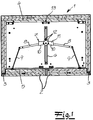
- den erfindungsgemäßen Sicherheitsschrank mit jeweils geschlossenen Drehflügeltüren im Schließbetrieb und
- Fig. 2
- den Gegenstand nach
Fig. 1 mit einer geöffneten Drehflügeltür im Normalbetrieb. - In den Figuren ist ein Sicherheitsschrank und insbesondere Gefahrstoffschrank dargestellt, der über einen Schrankkorpus 1 verfügt, an den Drehflügeltüren 2 angeschlossen sind. Die jeweilige Drehflügeltür 2 ist über eine jeweils randseitig des Schrankkorpus 1 angeordnete Drehachse 3 an den Schrankkorpus 1 angeschlossen. Sowohl der Schrankkorpus 1 als auch die zugehörige Drehflügeltür 2 verfügen über eine Innenverkleidung 4, 5, die aus nicht brennbaren bzw. schwer entflammbaren Werkstoffplatten aufgebaut sein mag. Man erkennt, dass vorliegend zwei Drehflügeltüren 2 realisiert sind, die gemeinsam an ein in einer Führung 6 verschiebbares Verbindungselement 7 angeschlossen sind.
- Anhand der Figuren erkennt man des Weiteren, dass das Verbindungselement 7 im Wesentlichen achsensymmetrisch im Vergleich zur mittigen Führung 6 ausgebildet ist. Außerdem erstreckt sich das Verbindungselement 7 im Wesentlichen quer im Vergleich zur Längserstreckung der Führung 6. Darüber hinaus ist die Führung 6 so ausgebildet und angeordnet, dass sie sich entlang einer durch einen Pfeil in der
Fig. 2 angedeuteten Schließbewegung der zugehörigen Drehflügeltür 2 respektive des Verbindungselementes 7 erstreckt. Vergleichbares gilt natürlich auch für die in Gegenrichtung verlaufende Öffnungsrichtung. - Das Verbindungselement 7 mag mit einer Rollenanordnung, einem Steg, einem Schwert oder dergleichen in die im Ausführungsbeispiel mit zwei Schienen mit mittiger Ausnehmung ausgerüstete Führung 6 eingreifen. Jedenfalls erfährt das Verbindungselement 7 entlang der Führung 6 eine lineare Verschiebung, sobald das Verbindungselement 7 von seiner üblicherweise im Normalbetrieb eingenommenen Öffnungsposition in der türseitigen Endstellung gegenüber der Führung 6 gemäß
Fig. 2 in die Schließposition mit mittiger Anordnung gegenüber der Führung 6 gemäßFig. 1 überführt wird. Die Schließposition des Verbindungselementes 7 nachFig. 1 korrespondiert zum Schließbetrieb, beispielsweise zu einem Brandfall. - In dieser Schließposition des Verbindungselementes 7 nimmt das Verbindungselement eine in etwa mittige Stellung im Vergleich zur längserstreckten Führung 6 ein. Dagegen korrespondiert die in der
Fig. 2 dargestellte Öffnungsposition des Verbindungselementes 7 und folglich der Normalbetrieb dazu, dass das Verbindungselement 7 seine türseitige Endstellung im Vergleich zu der besagten Führung 6 einnimmt. - Die jeweilige Drehflügeltür 2 ist mit Hilfe einer Gelenkanordnung 8, 9 an das Verbindungselement 7 angeschlossen. Tatsächlich setzt sich die Gelenkanordnung 8, 9 im Wesentlichen aus einem mit dem Verbindungselement 7 drehbar gekoppelten Verbindungsgelenkarm 8 und einem mit der zugehörigen Drehflügeltür 2 drehbar verbundenen Türgelenkarm 9 zusammen. Der Verbindungsgelenkarm 8 und der Türgelenkarm 9 sind ihrerseits gelenkig miteinander verbunden.
- Im Normalbetrieb liegt die Gelenkanordnung 8, 9 der im Zuge einer Öffnungsbewegung beaufschlagten Drehflügeltür 2 an einem Anschlag 10 des Verbindungselementes 7 an (vgl. die linke Drehflügeltür 2 in
Fig. 2 ). Tatsächlich ist das Verbindungselement 7 mit zwei türseitigen Anschlägen 10 für die jeweilige Gelenkanordnung 8, 9 ausgerüstet. Die fraglichen Anschläge 10 sind im Wesentlichen rechtwinklig an eine Anschlussplatte 11 als Bestandteil des Verbindungselementes 7 angeschlossen. In diesem Zusammenhang lassen sich die fragliche Anschlussplatte 11 und die zugehörigen Anschläge 10 besonders einfach und kostengünstig produzieren, nämlich durch übliche Metallstanz-/Biegevorgänge. - Die Anschlussplatte 11 ist mit Drehachsen 12 ausgerüstet, mit deren Hilfe die jeweilige Gelenkanordnung 8, 9 drehbar an das Verbindungselement 7 angeschlossen ist. Tatsächlich erfährt der jeweilige Verbindungsgelenkarm 8 mit Hilfe der Drehachsen 12 einen drehbaren Anschluss an das Verbindungselement 7 bzw. dessen Anschlussplatte 11. Man erkennt, dass die beiden Anschläge 10 insgesamt einen stumpfen Winkel zwischen sich einschließen.
- Von besonderer Bedeutung für die Erfindung ist nun der Umstand, dass bei einer Öffnungs- oder Schließbewegung der einen Drehflügeltür 2 im Normalbetrieb die jeweils andere Drehflügeltür 2 von dem Verbindungselement 7 mechanisch entkoppelt ist. Die Öffnungs- oder Schließbewegung der zugehörigen Drehflügeltür 2 im Normalbetrieb wird im Ausführungsbeispiel manuell bewerkstelligt. Grundsätzlich ist natürlich auch eine motorisch initiierte Öffnungs- oder Schließbewegung der Drehflügeltür 2 möglich.
- Die Funktionsweise ist wie folgt: Ausgehend von einer geschlossenen Position beider Drehflügeltüren 2 im Normalbetrieb gemäß der
Fig. 2 erkennt man, dass eine Öffnungsbewegung der in diesem Fall linken Drehflügeltür 2 zu einer Relativbewegung der Gelenkanordnung 8, 9 gegenüber dem Verbindungselement 7 korrespondiert. Das Verbindungselement 7 behält in dem Normalbetrieb seine Öffnungsposition gemäßFig. 2 bei, das heißt verbleibt in der endseitigen Stellung im Vergleich zur zugehörigen Führung 6. In dieser Öffnungsposition ist das Verbindungselement 7 fixiert. Hierfür mag eine thermisch lösbare und nicht näher dargestellte Brandschutzsicherung sorgen. - Sobald nun die betreffende Drehflügeltür 2 - im Ausführungsbeispiel die linke Drehflügeltür 2 - manuell geöffnet wird, geht die zugehörige Gelenkanordnung 8, 9 von ihrer zuvor eingenommenen und winklig abgespreizten Position im Vergleich zum Verbindungselement 7 in eine Stellung über, die zu einer Anlage der zugehörigen Gelenkanordnung 8, 9 an dem linken Anschlag 10 im Beispielfall korrespondiert. Ist der Anschlag 10 erreicht, so sorgt dieser Umstand zugleich dafür, dass ein etwaiger Öffnungswinkel der Drehflügeltür 2 auf ca. 90° gegenüber dem Schrankkorpus 1 im Beispielfall nach der
Fig. 2 begrenzt wird. Das gilt selbstverständlich nur beispielhaft. - Bei der beschriebenen Öffnungsbewegung der (linken) Drehflügeltür 2 behält das Verbindungselement 7 - wie beschrieben - seine Öffnungsposition in der türseitigen Endstellung gegenüber der Führung 6 bei. Hierzu korrespondiert der Normalbetrieb. Die (rechte) Drehflügeltür 2 verharrt demgegenüber in ihrer Schließposition. Das ist möglich, weil die zugehörige Gelenkanordnung 8, 9 der geschlossenen Drehflügeltür 2 von dem zugehörigen Anschlag 10 unverändert winklig absteht. Tatsächlich geht der Verbindungsgelenkarm 8 beim Übergang von der geöffneten Stellung der Drehflügeltür 2 von seiner Position in Anlage an dem Anschlag 10 in die demgegenüber winklig abstehende Stellung über, wie man bei einem Vergleich der beiden Drehflügeltüren 2 im Normalbetrieb der
Fig. 2 unschwer erkennen kann. Dabei lassen sich die beiden Drehflügeltüren 2 unabhängig voneinander betätigen, weil sie von dem zugehörigen Verbindungselement 7 frei und von diesem gleichsam mechanisch entkoppelt sind. - Der Schließbetrieb beispielsweise im Brandfall korrespondiert nun dazu, dass eine Federeinheit 13 zum Einsatz kommt. Das ist möglich, weil im Brandfall die das Verbindungselement 7 in der Öffnungsposition bzw. türseitigen Endstellung gegenüber der Führung 6 fixierende Brandschutzsicherung thermisch gelöst wird. Dadurch kann die Federeinheit 13 das Verbindungselement 7 nunmehr in Richtung auf die Schrankrückseite entlang der Führung 6 ziehen. Zugleich geht das Verbindungselement 7 von der Öffnungsposition entsprechend der
Fig. 2 in die Schließposition nach derFig. 1 über. Hierzu gehört der Schließbetrieb. - Bei diesem Vorgang werden beide Drehflügeltüren 2 - sofern geöffnet - gleichzeitig geschlossen. Denn sofern bei der Bewegung des Verbindungselementes 7 von seiner Öffnungsposition gemäß
Fig. 2 in die Schließposition nachFig. 1 in Richtung auf die Schrankrückseite eine oder beide Drehflügeltüren 2 geöffnet sind, sorgt diese Bewegung des Verbindungselementes 7 dafür, dass die betreffende Drehflügeltür 2 geschlossen wird. - Denn bei der jeweils geöffneten Drehflügeltür 2 liegt die Gelenkanordnung 8, 9 an dem Anschlag 10 an, so dass eine schließende Bewegung bzw. der Übergang des Verbindungselementes 7 von der Öffnungsposition nach
Fig. 2 in die Schließposition gemäßFig. 1 unmittelbar mit einer Beaufschlagung der Drehflügeltür 2 korrespondiert. Als Folge hiervon sind beide Drehflügeltüren 2 im Schließbetrieb respektive im Brandfall geschlossen. - Sofern eine oder beide Drehflügeltüren 2 in diesem Schließbetrieb bereits ihre Schließstellung eingenommen haben, wird das Verbindungselement 7 mit Hilfe der Federeinheit 13 entlang der Führung 6 verfahren, ohne dass die betreffende Drehflügeltür 2 eine Beaufschlagung erfährt. Denn bei diesem Vorgang wird lediglich der Verbindungsgelenkarm 8 von seiner winkligen Position in Anlage an den Anschlag 10 des Verbindungselementes 7 verbracht. Hierin sind die wesentlichen Vorteile zu sehen.
Claims (9)
- Sicherheitsschrank, insbesondere Gefahrstoffschrank, mit wenigstens zwei gemeinsam an ein in einer Führung (6) verschiebbares Verbindungselement (7) angeschlossenen Drehflügeltüren (2), wobei
die jeweilige Drehflügeltür (2) über eine jeweils randseitig eines Schrankkorpus (1) angeordnete Drehachse (3) an den Schrankkorpus (1) angeschlossen ist, wobei ferner
die jeweilige Drehflügeltür (2) der beiden Drehflügeltüren (2) mittels einer jeweils eigenen Gelenkanordnung (8, 9) an das Verbindungselement (7) angeschlossen ist und
das Verbindungselement (7) mit zwei türseitigen Anschlägen (10) für die jeweilige Gelenkanordnung (8, 9) ausgerüstet ist, und
wobei ein Normalbetrieb dazu korrespondiert, dass das Verbindungselement (7) seine Öffnungsposition und folglich türseitige Endstellung im Vergleich zu der Führung (6) einnimmt und beibehält, wobei bei einer Öffnungs- oder Schließbewegung der einen Drehflügeltür (2) im Normalbetrieb die jeweils andere Drehflügeltür (2) von dem Verbindungselement (7) mechanisch entkoppelt ist, indem
die Gelenkanordnung (8, 9) der im Zuge der Öffnungs- oder Schließbewegung im Normalbetrieb beaufschlagten Drehflügeltür (2) gegenüber dem Verbindungselement (7) verstellt wird und die Gelenkanordnung (8, 9) der im Zuge der Öffnungsbewegung beaufschlagten Drehflügeltür (2) im Normalbetrieb in der Öffnungsposition der Drehflügeltür an dem Anschlag (10) anliegt, während die andere Drehflügeltür (2) in ihrer Schließposition verharrt, und mit
einer Federeinheit (13), welche beide Drehflügeltüren (2) zumindest im Schließbetrieb in Richtung ihrer Schließstellung kraftbeaufschlagt, wobei beim Schließbetrieb das Verbindungselement (7) von seiner Öffnungsposition in eine Schließposition entlang der Führung (6) mittels der Federeinheit (13) überführt wird, wobei über die jeweils am Anschlag (10) des Verbindungselements (7) anliegende Gelenkanordnung (8, 9) die zugehörige Drehflügeltür (2) schließend beaufschlagt wird. - Schrank nach Anspruch 1, dadurch gekennzeichnet, dass die Öffnungs-oder Schließbewegung der Drehflügeltür (2) im Normalbetrieb manuell und/oder motorisch bewerkstelligt wird.
- Schrank nach Anspruch 1 oder 2, dadurch gekennzeichnet, dass sich die Gelenkanordnung (8, 9) im Wesentlichen aus einem mit dem Verbindungselement (7) drehbar gekoppelten Verbindungsgelenkarm (8) und einem mit der Drehflügeltür (2) drehbar verbundenen Türgelenkarm (9) zusammensetzt.
- Schrank nach einem der Ansprüche 1 bis 3, dadurch gekennzeichnet, dass die Schließposition des Verbindungselementes (7) zu einer in etwa mittigen Stellung im Vergleich zu einer längserstreckten Führung (6) korrespondiert.
- Schrank nach einem der Ansprüche 1 bis 4, dadurch gekennzeichnet, dass das Verbindungselement (7) symmetrisch im Vergleich zur mittigen Führung (6) ausgebildet ist.
- Schrank nach einem der Ansprüche 1 bis 5, dadurch gekennzeichnet, dass das Verbindungselement (7) eine Anschlussplatte (11) mit Drehachsen (12) zum drehbaren Anschluss der jeweiligen Gelenkanordnung (8, 9) aufweist.
- Schrank nach Anspruch 6, dadurch gekennzeichnet, dass die Anschläge (10) im Wesentlichen rechtwinklig an der Anschlussplatte (11) angeordnet sind.
- Schrank nach einem der Ansprüche 1 bis 7, dadurch gekennzeichnet, dass die Anschläge (10) einen stumpfen Winkel zwischen sich einschließen.
- Schrank nach einem der Ansprüche 1 bis 8, dadurch gekennzeichnet, dass die Gelenkanordnung (8, 9) in der Schließposition der jeweiligen Drehflügeltür (2) von dem Anschlag (10) winklig absteht.
Priority Applications (1)
| Application Number | Priority Date | Filing Date | Title |
|---|---|---|---|
| PL13167656T PL2677104T3 (pl) | 2012-06-18 | 2013-05-14 | Szafka bezpieczeństwa |
Applications Claiming Priority (2)
| Application Number | Priority Date | Filing Date | Title |
|---|---|---|---|
| DE202012102230U DE202012102230U1 (de) | 2012-06-18 | 2012-06-18 | Sicherheitsschrank |
| DE202012102586U DE202012102586U1 (de) | 2012-06-18 | 2012-07-12 | Sicherheitsschrank |
Publications (3)
| Publication Number | Publication Date |
|---|---|
| EP2677104A2 EP2677104A2 (de) | 2013-12-25 |
| EP2677104A3 EP2677104A3 (de) | 2015-10-07 |
| EP2677104B1 true EP2677104B1 (de) | 2018-04-25 |
Family
ID=46635689
Family Applications (1)
| Application Number | Title | Priority Date | Filing Date |
|---|---|---|---|
| EP13167656.1A Active EP2677104B1 (de) | 2012-06-18 | 2013-05-14 | Sicherheitsschrank |
Country Status (5)
| Country | Link |
|---|---|
| EP (1) | EP2677104B1 (de) |
| DE (2) | DE202012102230U1 (de) |
| ES (1) | ES2675552T3 (de) |
| PL (1) | PL2677104T3 (de) |
| TR (1) | TR201809309T4 (de) |
Families Citing this family (5)
| Publication number | Priority date | Publication date | Assignee | Title |
|---|---|---|---|---|
| ES2746539T3 (es) | 2015-10-01 | 2020-03-06 | Dueperthal Sicherheitstechnik Gmbh & Co Kg | Armario de seguridad |
| EP3356630B1 (de) * | 2015-10-01 | 2020-02-12 | Düperthal Sicherheitstechnik GmbH & Co.KG | Sicherheitsschrank |
| DE102016113822B4 (de) * | 2016-07-27 | 2021-04-15 | Asecos Gmbh | Gefahrstoffschrank |
| CN110159135B (zh) * | 2019-06-03 | 2020-08-14 | 秦皇岛职业技术学院 | 一种嵌入式高安全性金融票据存放装置 |
| CN110469231B (zh) * | 2019-08-29 | 2021-04-16 | 中国航空工业集团公司沈阳飞机设计研究所 | 一种对开活动舱门开闭连杆机构 |
Family Cites Families (4)
| Publication number | Priority date | Publication date | Assignee | Title |
|---|---|---|---|---|
| DE102004021912A1 (de) * | 2004-03-25 | 2005-10-13 | Asecos Gmbh | Sicherheitsschrank |
| DE202004004855U1 (de) | 2004-03-25 | 2004-08-12 | Asecos Gmbh | Sicherheitsschrank |
| DE502007001692D1 (de) | 2007-07-20 | 2009-11-19 | Dueperthal Sicherheitstechnik | Schrank, insbesondere Sicherheitsschrank |
| DE202009002534U1 (de) | 2009-02-21 | 2009-04-30 | Düperthal Sicherheitstechnik Gmbh & Co. Kg | Schrank, insbesondere Sicherheitsschrank |
-
2012
- 2012-06-18 DE DE202012102230U patent/DE202012102230U1/de not_active Expired - Lifetime
- 2012-07-12 DE DE202012102586U patent/DE202012102586U1/de not_active Expired - Lifetime
-
2013
- 2013-05-14 EP EP13167656.1A patent/EP2677104B1/de active Active
- 2013-05-14 TR TR2018/09309T patent/TR201809309T4/tr unknown
- 2013-05-14 ES ES13167656.1T patent/ES2675552T3/es active Active
- 2013-05-14 PL PL13167656T patent/PL2677104T3/pl unknown
Non-Patent Citations (1)
| Title |
|---|
| None * |
Also Published As
| Publication number | Publication date |
|---|---|
| DE202012102230U1 (de) | 2012-07-11 |
| EP2677104A3 (de) | 2015-10-07 |
| ES2675552T3 (es) | 2018-07-11 |
| DE202012102586U1 (de) | 2012-08-09 |
| PL2677104T3 (pl) | 2018-09-28 |
| TR201809309T4 (tr) | 2018-07-23 |
| EP2677104A2 (de) | 2013-12-25 |
Similar Documents
| Publication | Publication Date | Title |
|---|---|---|
| EP2893108B1 (de) | Kraftfahrzeugtürschloss | |
| EP3271535B1 (de) | Kraftfahrzeugtür | |
| EP2702218B1 (de) | Kraftfahrzeugtürverschluss | |
| EP1862618B1 (de) | Kraftfahrzeugtürverschluss | |
| EP2677104B1 (de) | Sicherheitsschrank | |
| EP2221438B1 (de) | Schrank, insbesondere Sicherheitsschrank | |
| EP2935736B1 (de) | Kraftfahrzeugtürverschluss | |
| DE102016107510A1 (de) | Kraftfahrzeugtürschloss | |
| WO2016146109A1 (de) | Kraftfahrzeugtür | |
| EP4112851B1 (de) | Kraftfahrzeug-schloss, insbesondere kraftfahrzeug-türschloss | |
| EP2017420B1 (de) | Schrank, insbesondere Sicherheitsschrank | |
| EP2715019B1 (de) | Kraftfahrzeugtürverschluss | |
| DE10236282B4 (de) | Kraftfahrzeugschloß mit zwei Sperrklinken | |
| DE102013014725A1 (de) | Kraftfahrzeugtürverschluss | |
| EP3117057A1 (de) | Kraftfahrzeugtürverschluss | |
| EP2603657B1 (de) | Schrank, insbesondere sicherheitsschrank | |
| DE2717232C2 (de) | Sicherheitstür für Schaltanlagenzelle | |
| WO2016062309A2 (de) | Kraftfahrzeugtürverschluss | |
| WO2024052381A1 (de) | Kraftfahrzeug-schloss insbesondere kraftfahrzeug-türschloss | |
| EP2017418B1 (de) | Schrank, insbesondere Falttüren Sicherheitsschrank | |
| EP2503085B1 (de) | Vorrichtung zum Festlegen einer Offenstellung eines Flügels eines Parallel-Ausstellfensters, einer Parallel-Ausstelltür oder dergleichen | |
| DE19532263A1 (de) | Vorrichtung zur Schließfolgeregelung für zweiflügelige Türen | |
| EP4133152A1 (de) | Kraftfahrzeug-schloss | |
| WO2008142125A1 (de) | Schiebetür für ein fahrzeug | |
| DE102016116616A1 (de) | Kraftfahrzeugtürschloss |
Legal Events
| Date | Code | Title | Description |
|---|---|---|---|
| PUAI | Public reference made under article 153(3) epc to a published international application that has entered the european phase |
Free format text: ORIGINAL CODE: 0009012 |
|
| AK | Designated contracting states |
Kind code of ref document: A2 Designated state(s): AL AT BE BG CH CY CZ DE DK EE ES FI FR GB GR HR HU IE IS IT LI LT LU LV MC MK MT NL NO PL PT RO RS SE SI SK SM TR |
|
| AX | Request for extension of the european patent |
Extension state: BA ME |
|
| PUAL | Search report despatched |
Free format text: ORIGINAL CODE: 0009013 |
|
| AK | Designated contracting states |
Kind code of ref document: A3 Designated state(s): AL AT BE BG CH CY CZ DE DK EE ES FI FR GB GR HR HU IE IS IT LI LT LU LV MC MK MT NL NO PL PT RO RS SE SI SK SM TR |
|
| AX | Request for extension of the european patent |
Extension state: BA ME |
|
| RIC1 | Information provided on ipc code assigned before grant |
Ipc: E05F 17/00 20060101AFI20150902BHEP Ipc: E05G 1/00 20060101ALI20150902BHEP Ipc: E05G 1/026 20060101ALI20150902BHEP Ipc: E05F 1/10 20060101ALI20150902BHEP Ipc: E05F 1/00 20060101ALN20150902BHEP |
|
| 17P | Request for examination filed |
Effective date: 20151111 |
|
| RBV | Designated contracting states (corrected) |
Designated state(s): AL AT BE BG CH CY CZ DE DK EE ES FI FR GB GR HR HU IE IS IT LI LT LU LV MC MK MT NL NO PL PT RO RS SE SI SK SM TR |
|
| GRAP | Despatch of communication of intention to grant a patent |
Free format text: ORIGINAL CODE: EPIDOSNIGR1 |
|
| RIC1 | Information provided on ipc code assigned before grant |
Ipc: E05G 1/00 20060101ALI20171221BHEP Ipc: E05F 17/00 20060101AFI20171221BHEP Ipc: E05F 1/10 20060101ALI20171221BHEP Ipc: E05G 1/026 20060101ALI20171221BHEP Ipc: E05F 1/00 20060101ALN20171221BHEP |
|
| GRAS | Grant fee paid |
Free format text: ORIGINAL CODE: EPIDOSNIGR3 |
|
| INTG | Intention to grant announced |
Effective date: 20180124 |
|
| GRAA | (expected) grant |
Free format text: ORIGINAL CODE: 0009210 |
|
| AK | Designated contracting states |
Kind code of ref document: B1 Designated state(s): AL AT BE BG CH CY CZ DE DK EE ES FI FR GB GR HR HU IE IS IT LI LT LU LV MC MK MT NL NO PL PT RO RS SE SI SK SM TR |
|
| REG | Reference to a national code |
Ref country code: GB Ref legal event code: FG4D Free format text: NOT ENGLISH |
|
| REG | Reference to a national code |
Ref country code: CH Ref legal event code: EP |
|
| REG | Reference to a national code |
Ref country code: AT Ref legal event code: REF Ref document number: 993100 Country of ref document: AT Kind code of ref document: T Effective date: 20180515 |
|
| REG | Reference to a national code |
Ref country code: IE Ref legal event code: FG4D Free format text: LANGUAGE OF EP DOCUMENT: GERMAN |
|
| REG | Reference to a national code |
Ref country code: DE Ref legal event code: R096 Ref document number: 502013009987 Country of ref document: DE |
|
| REG | Reference to a national code |
Ref country code: FR Ref legal event code: PLFP Year of fee payment: 6 |
|
| REG | Reference to a national code |
Ref country code: ES Ref legal event code: FG2A Ref document number: 2675552 Country of ref document: ES Kind code of ref document: T3 Effective date: 20180711 |
|
| REG | Reference to a national code |
Ref country code: NL Ref legal event code: FP |
|
| REG | Reference to a national code |
Ref country code: LT Ref legal event code: MG4D |
|
| PG25 | Lapsed in a contracting state [announced via postgrant information from national office to epo] |
Ref country code: BG Free format text: LAPSE BECAUSE OF FAILURE TO SUBMIT A TRANSLATION OF THE DESCRIPTION OR TO PAY THE FEE WITHIN THE PRESCRIBED TIME-LIMIT Effective date: 20180725 Ref country code: LT Free format text: LAPSE BECAUSE OF FAILURE TO SUBMIT A TRANSLATION OF THE DESCRIPTION OR TO PAY THE FEE WITHIN THE PRESCRIBED TIME-LIMIT Effective date: 20180425 Ref country code: FI Free format text: LAPSE BECAUSE OF FAILURE TO SUBMIT A TRANSLATION OF THE DESCRIPTION OR TO PAY THE FEE WITHIN THE PRESCRIBED TIME-LIMIT Effective date: 20180425 Ref country code: NO Free format text: LAPSE BECAUSE OF FAILURE TO SUBMIT A TRANSLATION OF THE DESCRIPTION OR TO PAY THE FEE WITHIN THE PRESCRIBED TIME-LIMIT Effective date: 20180725 Ref country code: SE Free format text: LAPSE BECAUSE OF FAILURE TO SUBMIT A TRANSLATION OF THE DESCRIPTION OR TO PAY THE FEE WITHIN THE PRESCRIBED TIME-LIMIT Effective date: 20180425 |
|
| PG25 | Lapsed in a contracting state [announced via postgrant information from national office to epo] |
Ref country code: GR Free format text: LAPSE BECAUSE OF FAILURE TO SUBMIT A TRANSLATION OF THE DESCRIPTION OR TO PAY THE FEE WITHIN THE PRESCRIBED TIME-LIMIT Effective date: 20180726 Ref country code: HR Free format text: LAPSE BECAUSE OF FAILURE TO SUBMIT A TRANSLATION OF THE DESCRIPTION OR TO PAY THE FEE WITHIN THE PRESCRIBED TIME-LIMIT Effective date: 20180425 Ref country code: LV Free format text: LAPSE BECAUSE OF FAILURE TO SUBMIT A TRANSLATION OF THE DESCRIPTION OR TO PAY THE FEE WITHIN THE PRESCRIBED TIME-LIMIT Effective date: 20180425 Ref country code: RS Free format text: LAPSE BECAUSE OF FAILURE TO SUBMIT A TRANSLATION OF THE DESCRIPTION OR TO PAY THE FEE WITHIN THE PRESCRIBED TIME-LIMIT Effective date: 20180425 |
|
| PG25 | Lapsed in a contracting state [announced via postgrant information from national office to epo] |
Ref country code: PT Free format text: LAPSE BECAUSE OF FAILURE TO SUBMIT A TRANSLATION OF THE DESCRIPTION OR TO PAY THE FEE WITHIN THE PRESCRIBED TIME-LIMIT Effective date: 20180827 |
|
| REG | Reference to a national code |
Ref country code: DE Ref legal event code: R097 Ref document number: 502013009987 Country of ref document: DE |
|
| REG | Reference to a national code |
Ref country code: BE Ref legal event code: MM Effective date: 20180531 |
|
| PG25 | Lapsed in a contracting state [announced via postgrant information from national office to epo] |
Ref country code: RO Free format text: LAPSE BECAUSE OF FAILURE TO SUBMIT A TRANSLATION OF THE DESCRIPTION OR TO PAY THE FEE WITHIN THE PRESCRIBED TIME-LIMIT Effective date: 20180425 Ref country code: CZ Free format text: LAPSE BECAUSE OF FAILURE TO SUBMIT A TRANSLATION OF THE DESCRIPTION OR TO PAY THE FEE WITHIN THE PRESCRIBED TIME-LIMIT Effective date: 20180425 Ref country code: DK Free format text: LAPSE BECAUSE OF FAILURE TO SUBMIT A TRANSLATION OF THE DESCRIPTION OR TO PAY THE FEE WITHIN THE PRESCRIBED TIME-LIMIT Effective date: 20180425 Ref country code: EE Free format text: LAPSE BECAUSE OF FAILURE TO SUBMIT A TRANSLATION OF THE DESCRIPTION OR TO PAY THE FEE WITHIN THE PRESCRIBED TIME-LIMIT Effective date: 20180425 Ref country code: MC Free format text: LAPSE BECAUSE OF FAILURE TO SUBMIT A TRANSLATION OF THE DESCRIPTION OR TO PAY THE FEE WITHIN THE PRESCRIBED TIME-LIMIT Effective date: 20180425 Ref country code: SK Free format text: LAPSE BECAUSE OF FAILURE TO SUBMIT A TRANSLATION OF THE DESCRIPTION OR TO PAY THE FEE WITHIN THE PRESCRIBED TIME-LIMIT Effective date: 20180425 |
|
| REG | Reference to a national code |
Ref country code: IE Ref legal event code: MM4A |
|
| PG25 | Lapsed in a contracting state [announced via postgrant information from national office to epo] |
Ref country code: IT Free format text: LAPSE BECAUSE OF FAILURE TO SUBMIT A TRANSLATION OF THE DESCRIPTION OR TO PAY THE FEE WITHIN THE PRESCRIBED TIME-LIMIT Effective date: 20180425 Ref country code: SM Free format text: LAPSE BECAUSE OF FAILURE TO SUBMIT A TRANSLATION OF THE DESCRIPTION OR TO PAY THE FEE WITHIN THE PRESCRIBED TIME-LIMIT Effective date: 20180425 |
|
| PLBE | No opposition filed within time limit |
Free format text: ORIGINAL CODE: 0009261 |
|
| STAA | Information on the status of an ep patent application or granted ep patent |
Free format text: STATUS: NO OPPOSITION FILED WITHIN TIME LIMIT |
|
| PG25 | Lapsed in a contracting state [announced via postgrant information from national office to epo] |
Ref country code: LU Free format text: LAPSE BECAUSE OF NON-PAYMENT OF DUE FEES Effective date: 20180514 |
|
| 26N | No opposition filed |
Effective date: 20190128 |
|
| PG25 | Lapsed in a contracting state [announced via postgrant information from national office to epo] |
Ref country code: IE Free format text: LAPSE BECAUSE OF NON-PAYMENT OF DUE FEES Effective date: 20180514 |
|
| PG25 | Lapsed in a contracting state [announced via postgrant information from national office to epo] |
Ref country code: SI Free format text: LAPSE BECAUSE OF FAILURE TO SUBMIT A TRANSLATION OF THE DESCRIPTION OR TO PAY THE FEE WITHIN THE PRESCRIBED TIME-LIMIT Effective date: 20180425 Ref country code: BE Free format text: LAPSE BECAUSE OF NON-PAYMENT OF DUE FEES Effective date: 20180531 |
|
| REG | Reference to a national code |
Ref country code: AT Ref legal event code: MM01 Ref document number: 993100 Country of ref document: AT Kind code of ref document: T Effective date: 20180514 |
|
| PG25 | Lapsed in a contracting state [announced via postgrant information from national office to epo] |
Ref country code: AT Free format text: LAPSE BECAUSE OF NON-PAYMENT OF DUE FEES Effective date: 20180514 |
|
| PG25 | Lapsed in a contracting state [announced via postgrant information from national office to epo] |
Ref country code: AL Free format text: LAPSE BECAUSE OF FAILURE TO SUBMIT A TRANSLATION OF THE DESCRIPTION OR TO PAY THE FEE WITHIN THE PRESCRIBED TIME-LIMIT Effective date: 20180425 |
|
| PG25 | Lapsed in a contracting state [announced via postgrant information from national office to epo] |
Ref country code: MT Free format text: LAPSE BECAUSE OF FAILURE TO SUBMIT A TRANSLATION OF THE DESCRIPTION OR TO PAY THE FEE WITHIN THE PRESCRIBED TIME-LIMIT Effective date: 20180425 |
|
| PG25 | Lapsed in a contracting state [announced via postgrant information from national office to epo] |
Ref country code: HU Free format text: LAPSE BECAUSE OF FAILURE TO SUBMIT A TRANSLATION OF THE DESCRIPTION OR TO PAY THE FEE WITHIN THE PRESCRIBED TIME-LIMIT; INVALID AB INITIO Effective date: 20130514 |
|
| PG25 | Lapsed in a contracting state [announced via postgrant information from national office to epo] |
Ref country code: MK Free format text: LAPSE BECAUSE OF NON-PAYMENT OF DUE FEES Effective date: 20180425 Ref country code: CY Free format text: LAPSE BECAUSE OF FAILURE TO SUBMIT A TRANSLATION OF THE DESCRIPTION OR TO PAY THE FEE WITHIN THE PRESCRIBED TIME-LIMIT Effective date: 20180425 |
|
| PG25 | Lapsed in a contracting state [announced via postgrant information from national office to epo] |
Ref country code: IS Free format text: LAPSE BECAUSE OF FAILURE TO SUBMIT A TRANSLATION OF THE DESCRIPTION OR TO PAY THE FEE WITHIN THE PRESCRIBED TIME-LIMIT Effective date: 20180825 |
|
| REG | Reference to a national code |
Ref country code: CH Ref legal event code: PFA Owner name: DUEPERTHAL SICHERHEITSTECHNIK GMBH AND CO.KG, DE Free format text: FORMER OWNER: DUEPERTHAL SICHERHEITSTECHNIK GMBH AND CO.KG, DE |
|
| PGFP | Annual fee paid to national office [announced via postgrant information from national office to epo] |
Ref country code: NL Payment date: 20230519 Year of fee payment: 11 Ref country code: FR Payment date: 20230526 Year of fee payment: 11 Ref country code: DE Payment date: 20230412 Year of fee payment: 11 Ref country code: CH Payment date: 20230602 Year of fee payment: 11 |
|
| PGFP | Annual fee paid to national office [announced via postgrant information from national office to epo] |
Ref country code: TR Payment date: 20230512 Year of fee payment: 11 Ref country code: PL Payment date: 20230505 Year of fee payment: 11 |
|
| PGFP | Annual fee paid to national office [announced via postgrant information from national office to epo] |
Ref country code: GB Payment date: 20230524 Year of fee payment: 11 Ref country code: ES Payment date: 20230725 Year of fee payment: 11 |