EP2676070B1 - Fassadenleuchte mit leuchtdioden - Google Patents
Fassadenleuchte mit leuchtdioden Download PDFInfo
- Publication number
- EP2676070B1 EP2676070B1 EP12705839.4A EP12705839A EP2676070B1 EP 2676070 B1 EP2676070 B1 EP 2676070B1 EP 12705839 A EP12705839 A EP 12705839A EP 2676070 B1 EP2676070 B1 EP 2676070B1
- Authority
- EP
- European Patent Office
- Prior art keywords
- light
- façade
- housing
- light according
- emitting diodes
- Prior art date
- Legal status (The legal status is an assumption and is not a legal conclusion. Google has not performed a legal analysis and makes no representation as to the accuracy of the status listed.)
- Active
Links
- 238000001816 cooling Methods 0.000 claims description 22
- 238000009826 distribution Methods 0.000 claims description 9
- 229920003229 poly(methyl methacrylate) Polymers 0.000 claims description 6
- 239000004926 polymethyl methacrylate Substances 0.000 claims description 6
- 239000004417 polycarbonate Substances 0.000 claims description 5
- 229920000515 polycarbonate Polymers 0.000 claims description 5
- 229910052782 aluminium Inorganic materials 0.000 claims description 3
- XAGFODPZIPBFFR-UHFFFAOYSA-N aluminium Chemical compound [Al] XAGFODPZIPBFFR-UHFFFAOYSA-N 0.000 claims description 3
- 238000001746 injection moulding Methods 0.000 claims description 3
- 229910052751 metal Inorganic materials 0.000 claims description 2
- 239000002184 metal Substances 0.000 claims description 2
- 210000001331 nose Anatomy 0.000 claims 2
- -1 poly(methyl methacrylate) Polymers 0.000 claims 2
- 238000004512 die casting Methods 0.000 claims 1
- 229920002994 synthetic fiber Polymers 0.000 claims 1
- 210000004907 gland Anatomy 0.000 description 3
- 239000003086 colorant Substances 0.000 description 2
- 238000004519 manufacturing process Methods 0.000 description 2
- 230000004308 accommodation Effects 0.000 description 1
- 238000010276 construction Methods 0.000 description 1
- 238000005336 cracking Methods 0.000 description 1
- 239000013078 crystal Substances 0.000 description 1
- 239000000428 dust Substances 0.000 description 1
- 230000000694 effects Effects 0.000 description 1
- 230000007613 environmental effect Effects 0.000 description 1
- 238000005286 illumination Methods 0.000 description 1
- 238000009434 installation Methods 0.000 description 1
- 230000003287 optical effect Effects 0.000 description 1
- 230000002093 peripheral effect Effects 0.000 description 1
- 239000004033 plastic Substances 0.000 description 1
- 229920003023 plastic Polymers 0.000 description 1
- 238000002360 preparation method Methods 0.000 description 1
- 238000007789 sealing Methods 0.000 description 1
Images


Classifications
-
- F—MECHANICAL ENGINEERING; LIGHTING; HEATING; WEAPONS; BLASTING
- F21—LIGHTING
- F21V—FUNCTIONAL FEATURES OR DETAILS OF LIGHTING DEVICES OR SYSTEMS THEREOF; STRUCTURAL COMBINATIONS OF LIGHTING DEVICES WITH OTHER ARTICLES, NOT OTHERWISE PROVIDED FOR
- F21V15/00—Protecting lighting devices from damage
- F21V15/01—Housings, e.g. material or assembling of housing parts
- F21V15/013—Housings, e.g. material or assembling of housing parts the housing being an extrusion
-
- F—MECHANICAL ENGINEERING; LIGHTING; HEATING; WEAPONS; BLASTING
- F21—LIGHTING
- F21V—FUNCTIONAL FEATURES OR DETAILS OF LIGHTING DEVICES OR SYSTEMS THEREOF; STRUCTURAL COMBINATIONS OF LIGHTING DEVICES WITH OTHER ARTICLES, NOT OTHERWISE PROVIDED FOR
- F21V23/00—Arrangement of electric circuit elements in or on lighting devices
- F21V23/02—Arrangement of electric circuit elements in or on lighting devices the elements being transformers, impedances or power supply units, e.g. a transformer with a rectifier
-
- F—MECHANICAL ENGINEERING; LIGHTING; HEATING; WEAPONS; BLASTING
- F21—LIGHTING
- F21V—FUNCTIONAL FEATURES OR DETAILS OF LIGHTING DEVICES OR SYSTEMS THEREOF; STRUCTURAL COMBINATIONS OF LIGHTING DEVICES WITH OTHER ARTICLES, NOT OTHERWISE PROVIDED FOR
- F21V29/00—Protecting lighting devices from thermal damage; Cooling or heating arrangements specially adapted for lighting devices or systems
- F21V29/50—Cooling arrangements
- F21V29/502—Cooling arrangements characterised by the adaptation for cooling of specific components
- F21V29/507—Cooling arrangements characterised by the adaptation for cooling of specific components of means for protecting lighting devices from damage, e.g. housings
-
- F—MECHANICAL ENGINEERING; LIGHTING; HEATING; WEAPONS; BLASTING
- F21—LIGHTING
- F21V—FUNCTIONAL FEATURES OR DETAILS OF LIGHTING DEVICES OR SYSTEMS THEREOF; STRUCTURAL COMBINATIONS OF LIGHTING DEVICES WITH OTHER ARTICLES, NOT OTHERWISE PROVIDED FOR
- F21V29/00—Protecting lighting devices from thermal damage; Cooling or heating arrangements specially adapted for lighting devices or systems
- F21V29/50—Cooling arrangements
- F21V29/502—Cooling arrangements characterised by the adaptation for cooling of specific components
- F21V29/508—Cooling arrangements characterised by the adaptation for cooling of specific components of electrical circuits
-
- F—MECHANICAL ENGINEERING; LIGHTING; HEATING; WEAPONS; BLASTING
- F21—LIGHTING
- F21V—FUNCTIONAL FEATURES OR DETAILS OF LIGHTING DEVICES OR SYSTEMS THEREOF; STRUCTURAL COMBINATIONS OF LIGHTING DEVICES WITH OTHER ARTICLES, NOT OTHERWISE PROVIDED FOR
- F21V29/00—Protecting lighting devices from thermal damage; Cooling or heating arrangements specially adapted for lighting devices or systems
- F21V29/50—Cooling arrangements
- F21V29/70—Cooling arrangements characterised by passive heat-dissipating elements, e.g. heat-sinks
- F21V29/74—Cooling arrangements characterised by passive heat-dissipating elements, e.g. heat-sinks with fins or blades
- F21V29/76—Cooling arrangements characterised by passive heat-dissipating elements, e.g. heat-sinks with fins or blades with essentially identical parallel planar fins or blades, e.g. with comb-like cross-section
- F21V29/763—Cooling arrangements characterised by passive heat-dissipating elements, e.g. heat-sinks with fins or blades with essentially identical parallel planar fins or blades, e.g. with comb-like cross-section the planes containing the fins or blades having the direction of the light emitting axis
-
- F—MECHANICAL ENGINEERING; LIGHTING; HEATING; WEAPONS; BLASTING
- F21—LIGHTING
- F21V—FUNCTIONAL FEATURES OR DETAILS OF LIGHTING DEVICES OR SYSTEMS THEREOF; STRUCTURAL COMBINATIONS OF LIGHTING DEVICES WITH OTHER ARTICLES, NOT OTHERWISE PROVIDED FOR
- F21V17/00—Fastening of component parts of lighting devices, e.g. shades, globes, refractors, reflectors, filters, screens, grids or protective cages
- F21V17/10—Fastening of component parts of lighting devices, e.g. shades, globes, refractors, reflectors, filters, screens, grids or protective cages characterised by specific fastening means or way of fastening
- F21V17/16—Fastening of component parts of lighting devices, e.g. shades, globes, refractors, reflectors, filters, screens, grids or protective cages characterised by specific fastening means or way of fastening by deformation of parts; Snap action mounting
- F21V17/164—Fastening of component parts of lighting devices, e.g. shades, globes, refractors, reflectors, filters, screens, grids or protective cages characterised by specific fastening means or way of fastening by deformation of parts; Snap action mounting the parts being subjected to bending, e.g. snap joints
-
- F—MECHANICAL ENGINEERING; LIGHTING; HEATING; WEAPONS; BLASTING
- F21—LIGHTING
- F21W—INDEXING SCHEME ASSOCIATED WITH SUBCLASSES F21K, F21L, F21S and F21V, RELATING TO USES OR APPLICATIONS OF LIGHTING DEVICES OR SYSTEMS
- F21W2131/00—Use or application of lighting devices or systems not provided for in codes F21W2102/00-F21W2121/00
- F21W2131/10—Outdoor lighting
- F21W2131/107—Outdoor lighting of the exterior of buildings
-
- F—MECHANICAL ENGINEERING; LIGHTING; HEATING; WEAPONS; BLASTING
- F21—LIGHTING
- F21Y—INDEXING SCHEME ASSOCIATED WITH SUBCLASSES F21K, F21L, F21S and F21V, RELATING TO THE FORM OR THE KIND OF THE LIGHT SOURCES OR OF THE COLOUR OF THE LIGHT EMITTED
- F21Y2115/00—Light-generating elements of semiconductor light sources
- F21Y2115/10—Light-emitting diodes [LED]
Definitions
- the invention relates to a facade light with a housing for receiving bulbs and control gear.
- a facade light with a housing for receiving bulbs and control gear.
- LED light-emitting diodes
- a façade luminaire is known, are arranged in the light emitting diodes of different colors in a row one behind the other. Each individual LED is assigned an optic.
- the housing is designed so that it is also suitable for cooling the light-emitting diodes.
- a disadvantage of the known facade lamp of WO 2005/024291 A2 is that their height is relatively high.
- Object of the present invention is to develop a facade lamp of the type mentioned so that it can be performed as small as possible. For this purpose, a number of measures are required, which are given in the characterizing features of claim 1.
- each LED cluster is associated with an optics through which passes the light emitted by the LEDs of the LED cluster light.
- the optics are arranged and configured such that the light emitted by the light-emitting diodes of the LED cluster passes through the optics, the optics being designed such that it generates an elliptical light distribution. This ensures that a wide area of a façade can be uniformly illuminated from a central point, namely an approximately punctiform light source. If several façade luminaires are objected to one another and arranged next to one another, then by overlaying the individual elliptical light distributions at least approximately a broad strip of a façade can be illuminated.
- the housing is subdivided into at least two sections, wherein in a first section there is room for operating devices and in a second section arranged laterally next to the first section at least one LED cluster is arranged. Further, each of the LED clusters is cooled and coupled thereto by appropriate means for dissipating the heat generated during operation of the light emitting diodes. In total allow all these features that the facade light can be made with very small dimensions, especially with very low height.
- a narrow embodiment of the luminaire is achieved in that the LED clusters are arranged side by side, substantially along a straight line, wherein the straight line runs parallel to the longitudinal extent of the elliptical light distribution.
- the low overall height is of great importance, among other things, because façade luminaires are usually mounted on window parapets or façade elements, but for architectural reasons, it is endeavored to place the façade luminaire in such a way that it is not or at least barely visible to a viewer of the building is seen. If the façade luminaire has a sufficiently low overall height, then it can no longer be seen from a certain viewing angle, because it is covered by window parapets or façade elements.
- the façade luminaire has a housing which is subdivided into three sections, wherein in the middle section there is space for operating devices and in each case at least one LED cluster is arranged in the lateral sections.
- the middle section there is space for operating devices and in each case at least one LED cluster is arranged in the lateral sections.
- the means for dissipating the heat may according to a preferred embodiment have air gaps, which are formed in the housing, in particular between a receiving area for the LED cluster and a circumferential housing wall. It has been shown that a very effective dissipation of heat can be achieved by this measure despite compact design of the lamp, which is essential for reliable operation of the lamp.
- the LED clusters can also be cooled by means of one or more heat sinks, wherein these are also placed or formed in the lateral sections of the housing.
- An LED cluster consists of at least two light emitting diodes, preferably three light emitting diodes of different color and or color temperature.
- the light-emitting diodes are preferably arranged on a first side of circuit boards, in particular metal core boards. The boards are in this case on the opposite side of the first side in heat-conducting connection with the heat sink.
- the heat sink may be integrally formed and is accordingly also divided into three sections when dividing the housing into three sections.
- the first section is the heat sink with the first side section of the housing arranged board thermally conductively connected in the second or middle section of the heat sink bridges the space for the operating devices and in the second lateral portion of the heat sink is thermally conductively connected to the arranged in the third portion of the housing board.
- the housing can When the housing can, if it is formed by a lower housing part and by an upper housing part, the lower housing part be designed as a heat sink. In this case, a preferred option is for the production of the housing lower part as aluminum die cast.
- the heat sink in the region of the lateral sections on cooling fins, which rise from one side of a base, wherein the height of the cooling fins corresponds approximately to the depth of the space which is provided for receiving operating devices.
- the opposite side of the base from the aforementioned side can serve as a contact surface between the printed circuit board and the heat sink.
- the heat sink can form in the middle section a space except for the topside all around closed space for receiving control gear.
- the upper housing part is preferably made of plastic, wherein light-tight areas of polycarbonate and translucent areas of polymethyl methacrylate are made and the upper housing part is made by means of 2-component injection molding.
- This combination is particularly advantageous in the façade luminaire according to the invention, because clear, translucent polycarbonate yellows under sunlight, while polymethyl methacrylate is hardly susceptible here.
- polymethyl methacrylate is not well suited to realize the snap closures described below because polymethyl methacrylate is more brittle and more susceptible to stress cracking than polycarbonate.
- a façade luminaire must normally be made weatherproof, i. the interface between the upper part of the housing and the lower part of the housing must be sealed against the ingress of dirt and moisture.
- the lower housing part may have a peripheral web on which a circumferential seal is arranged. If then the upper housing part is fastened by means of a snap connection to the lower housing part, the upper housing part can be pressed against the seal, whereby it is clamped between the upper housing part and the lower housing part and thus ensures the tightness.
- the snap connection can be realized in that the upper housing part laterally engages over the lower housing part or - in the case of using the air gaps - engages in the running on the inner circumference of the housing lower part air gaps, wherein in the Recesses are provided in the snap-in lugs engage when the lower housing part is closed with the upper housing part, wherein the snap lugs are integrally formed on the lower housing part.
- This closure is characterized in particular by the fact that the lamp can be closed without tools and quickly, the tightness is guaranteed.
- facades often use a very large number of such luminaires.
- ease of assembly for facade builders or electricians in the selection of such lights is an important criterion.
- the invention also relates to a luminaire of higher protection with such a closure.
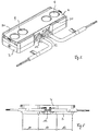
- FIG. 1 an exploded view of a first embodiment of a facade lamp according to the invention is shown.
- the facade lamp has a housing which consists of a housing lower part 3 and a housing upper part 4.
- the lower housing part is divided into three sections A1, A2, A3.
- two LED clusters 1 are arranged in the lateral sections A1 and A3.
- An LED cluster 1 is formed from at least two light-emitting diodes.
- three LEDs per LED cluster 1 are used, namely with the colors red, green and blue; It is also possible to use two preferably three white LEDs per LED cluster 1.
- an optical system 2 Seen in the light exit direction in front of each LED cluster 1, an optical system 2 is arranged.
- This optic 2 generates an elliptical light distribution on the illuminated surface.
- the four LED clusters 1, together with the total of four optics 2 produce a light distribution which illuminates a broad strip on the surface to be illuminated, that is, as a rule, on a facade or wall.
- a narrow construction of the façade luminaire is ensured by the fact that the LED clusters are arranged side by side, in particular substantially along a straight line. This straight line runs parallel to the longitudinal extension of the elliptical light distribution, preferably centrally through the luminaire.
- the LEDs of the LED cluster 1 are mounted on boards 5 or soldered. As in FIG. 2 it can be seen that the boards 5 are located with their backs on a contact surface 8 of the base 7 of the heat sink.
- the lower housing part 3 at the same time designed as a heat sink.
- the lower housing part 3 in the region of the lateral sections A1 and A3 on cooling fins 6, which are integrally formed on the base 7.
- the cooling fins 6 extend in the longitudinal direction of the lower housing part 3.
- the lower housing part is surrounded by substantially straight and smooth outer walls. This shape design is possible because the lower housing part 3 is designed as an aluminum die cast part.
- the frontal outer walls can be omitted to allow for improved air circulation.
- the height of the cooling fins 6 with base 7 corresponds approximately to the depth of the receiving space 15.
- the middle section A2 (not shown) operating devices, such as LED drivers or control units, such as DMX controllers and (not shown) electrical terminals are housed.
- the electrical supply is via standard cable glands through which a (not shown) cable can be passed and the housing and cable seal against each other.
- the façade luminaire according to the invention is supplied via a low-voltage power supply with 24 V or 48 V, the supply unit, ie the LED driver is usually placed outside of the lamp and in the space provided usually only the control unit together with (not shown) terminals is arranged.
- the receiving space 15 and the two lateral sections A1 and A3 are closed to the top with a circumferential ridge 10.
- This web 10 receives a circumferential seal 11, wherein the profile of this seal - as in FIG. 2 seen - the contour of the web 11 is adjusted. Also in FIG. 2 it can be seen that the seal 11 engages in a circumferential groove 16 of the housing upper part 4.
- the upper housing part 4 is formed from an opaque part, which is preferably made of polycarbonate and in the present embodiment of four circularly designed translucent, crystal clear cover elements 9, which are preferably made of polymethyl methacrylate.
- the production of the upper housing part 4 can be done by means of 2K injection molding.
- FIG. 3 is a front view of the embodiment according to FIG. 1 shown.
- the upper housing part 4 engages over the lower housing part 3 with tab-like side walls 14, wherein recesses 17 are provided in the side walls, which cooperate with snap lugs 12 and form the snap lock between the upper housing part 4 and lower housing part 3.
- a total of nine snap tabs 12 are distributed over the tab-like side wall on one side of the housing base 3.
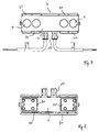
- FIGS. 5 to 8 A second embodiment of a facade light according to the invention is in the FIGS. 5 to 8 represented, wherein like elements are provided with the same reference numerals.
- this second exemplary embodiment is the same as the example of FIGS. 1 to 4 .
- the means for influencing the light output are identical here, which is why below the differences are to be explained in the first place.
- An essential difference in this second embodiment consists in the fact that the removal of the heat occurring during the LED operation takes place primarily with the aid of air slots 20, which are formed in the vicinity of the LED cluster 1 in the housing.
- these louvers 20 are formed on the inner circumference of the wall of the lower housing part 3, which is achieved by a corresponding - at least partially - double-walled design of the housing wall.
- the upper housing part 4 then no longer completely overlaps the housing lower part 3, but instead is configured such that the side wall 14 engages with the tabs in the air slot (s) 20 and interacts with snap-action lugs located here.
- the lower housing part 3 Only in the central region A2 in the region of the cable glands 13, the lower housing part 3 is not double-walled, so that here a tab engages over the lower housing part 3.
- the width of the louvers 20 is dimensioned such that, despite engagement of the side wall 14, sufficient free space remains, which allows a passage of air and, accordingly, an effective dissipation of heat.
- the located on the lower housing part 3 web 10 for receiving the seal 11 is slightly offset in this case formed on the inside of the louvers 20, so that still the required reliable sealing of the lamp is achieved.
- louvers 20 are respectively formed on the two longitudinal sides of the housing in the region of the lateral portions A1 and A3 for receiving the LED cluster 1, through which a very effective dissipation of the heat is achieved. It has been found that the effect of these louvers 20 is even so effective that no further measures for cooling would be required. Accordingly, in this embodiment, also on the arranged below the LED cluster 1 cooling fins 6, as in the example of the FIGS. 1 to 4 are provided, are waived. Instead, it is merely provided in this variant that substantially square depressions 21 are formed in these areas on the underside of the housing lower part 3. The preparation of the turn, preferably designed as Aluminium horrgußteil housing lower part 3 is thereby simplified. Of course, it would be conceivable, however, to increase the cooling capacity, even in this second embodiment form additional cooling fins, if this seems reasonable due to the environmental influences.
Description
- Die Erfindung betrifft eine Fassadenleuchte mit einem Gehäuse zur Aufnahme von Leuchtmitteln und Betriebsgeräten. Insbesondere dann, wenn mit Fassadeleuchten Farbspiele auf einer Fassade dargestellt werden sollen, kommen heutzutage meist Leuchtdioden (LED) als Leuchtmittel zum Einsatz.
- Aus der
WO 2005/024291 A2 ist eine Fassadenleuchte bekannt, bei der Leuchtdioden unterschiedlicher Farben in einer Reihe hintereinander angeordnet sind. Jeder einzelnen Leuchtdiode ist eine Optik zugeordnet. Das Gehäuse ist so ausgebildet, dass es auch zur Kühlung der Leuchtdioden geeignet ist. - Die Verwendung von Leuchtdioden als Lichtquellen ist auch aus der
US 7,434,959 B1 bekannt. Dieses Dokument zeigt eine Leuchte zur Straßenbeleuchtung, bei der die Leuchtdioden in drei Reihen auf eine gewölbten Bodenfläche angeordnet sind, um eine konzentrierte Lichtabgabe auf einen zu beleuchtenden Bereich zu erzielen. - Nachteilig bei der vorbekannten Fassadenleuchte der
WO 2005/024291 A2 ist, dass deren Bauhöhe verhältnismäßig hoch ist. - Aufgabe der vorliegenden Erfindung ist es, eine Fassadenleuchte der eingangs genannten Art so weiterzubilden, dass diese möglichst kleinbauend ausgeführt werden kann. Hierzu ist eine Reihe von Maßnahmen erforderlich, die in den kennzeichnenden Merkmalen des Anspruchs 1 angeführt sind.
- Erfindungsgemäß werden die Leuchtdioden in LED-Clustern angeordnet, wobei jedem LED-Cluster eine Optik zugeordnet ist, durch die das von den Leuchtdioden des LED-Clusters abgegebene Licht hindurch tritt. Hierbei ist die Optik derart angeordnet und ausgestaltet, dass das von den Leuchtdioden des LED-Clusters abgegebene Licht durch die Optik hindurch tritt, wobei die Optik derart ausgelegt ist, dass diese eine elliptische Lichtverteilung erzeugt. Hierdurch wird erreicht, dass ein weiter Bereich einer Fassade von einem zentralen Punkt, nämlich einer in etwa punktförmigen Lichtquelle, aus gleichmäßig beleuchtet werden kann. Werden mehrere Fassadenleuchten beanstandet zueinander und nebeneinander angeordnet, so kann durch Überlagerung der einzelnen elliptischen Lichtverteilungen zumindest angenähert ein breiter Streifen einer Fassade beleuchtet werden.
- Ferner ist wesentlich, dass das Gehäuse in wenigstens zwei Abschnitte unterteilt ist, wobei in einem ersten Abschnitt Raum für Betriebsgeräte ist und in einem zweiten seitlich neben dem ersten Abschnitt angeordneten Abschnitt wenigstens ein LED-Cluster angeordnet ist. Ferner ist jeder der LED-Cluster gekühlt und hierzu mit entsprechenden Mitteln zum Abführen der während des Betriebs der Leuchtdioden entstehenden Wärme gekoppelt. In Summe ermöglichen alle diese Merkmale, dass die Fassadenleuchte mit sehr geringen Abmessungen, insbesondere mit sehr geringer Bauhöhe ausgeführt werden kann. Eine schmale Ausführungsform für die Leuchte wird hierbei dadurch erzielt, dass die LED-Cluster nebeneinander, im Wesentlichen entlang einer Geraden angeordnet sind, wobei die Gerade parallel zur Längserstreckung der elliptischen Lichtverteilung verläuft.
- Bei Fassadenleuchten ist die geringe Bauhöhe unter anderem deshalb von großer Bedeutung, weil Fassadenleuchten in der Regel auf Fensterbrüstungen oder Fassadenelementen montiert werden, man aber aus architektonischen Gründe bestrebt ist, die Fassadenleuchte so zu platzieren, dass sie von einem Betrachter des Gebäudes nicht oder zumindest kaum gesehen wird. Weist die Fassadenleuchte eine ausreichend geringe Bauhöhe auf, so kann sie ab einem bestimmten Betrachtungswinkel nicht mehr gesehen werden, weil sie von Fensterbrüstungen oder Fassadenelementen verdeckt ist.
- In einer bevorzugten Ausführungsform weist die Fassadenleuchte ein Gehäuse auf, welches in drei Abschnitte unterteilt ist, wobei im mittleren Abschnitt Raum für Betriebsgeräte ist und in den seitlichen Abschnitten jeweils wenigstens ein LED-Cluster angeordnet ist. In dieser Anordnung ist es in besonders vorteilhafter Weise möglich die Überlagerung der elliptischen Lichtverteilung und damit die streifenförmige Beleuchtung einer Fassade zu realisieren. Dies gilt umso mehr bei einer Ausführungsform der Erfindung bei der in den seitlichen Abschnitten jeweils zwei LED-Cluster angeordnet sind.
- Die Mittel zum Abführen der Wärme können gemäß einer bevorzugten Ausführungsform Luftspalte aufweisen, welche im Gehäuse, insbesondere zwischen einem Aufnahmebereich für die LED-Cluster und einer umlaufenden Gehäusewand ausgebildet sind. Es hat sich gezeigt, dass durch diese Maßnahme trotz kompakter Bauweise der Leuchte ein sehr effektives Abführen der Wärme erzielt werden kann, was für einen zuverlässigen Betrieb der Leuchte unerlässlich ist.
- Alternativ oder ergänzend zur Verwendung der Luftspalte können die LED-Cluster allerdings auch mittels eines oder mehrerer Kühlkörper gekühlt werden, wobei diese ebenfalls in den seitlichen Abschnitten des Gehäuses platziert bzw. ausgebildet sind. Ein LED-Cluster besteht aus wenigstens zwei Leuchtdioden, bevorzugt drei Leuchtdioden unterschiedlicher Farbe und oder Farbtemperatur. Die Leuchtdioden werden bevorzugt auf einer ersten Seite von Platinen, insbesondere Metallkernplatinen, angeordnet. Die Platinen stehen hierbei auf der der ersten Seite gegenüberliegenden Seite in wärmeleitender Verbindung mit dem Kühlkörper.
- Vorzugsweise kann der Kühlkörper einstückig ausgebildet sein und ist dementsprechend bei einer Unterteilung des Gehäuses in drei Abschnitte ebenfalls in drei Abschnitte unterteilt. Im ersten Abschnitt ist der Kühlkörper mit der im ersten seitlichen Abschnitt des Gehäuses angeordneten Platine wärmeleitend verbunden, im zweiten bzw. mittleren Abschnitt überbrückt der Kühlkörper den Raum für die Betriebsgeräte und im zweiten seitlichen Abschnitt ist der Kühlkörper mit der im dritten Abschnitt des Gehäuses angeordneten Platine wärmeleitend verbunden.
- Beim Gehäuse kann, sofern es durch ein Gehäuseunterteil und durch ein Gehäuseoberteil gebildet ist, das Gehäuseunterteil als Kühlkörper ausgeführt sein. In diesem Fall ist für die Fertigung des Gehäuseunterteils als Aludruckguss eine bevorzugte Möglichkeit.
- Bevorzugt weist der Kühlkörper im Bereich der seitlichen Abschnitte Kühlrippen auf, die sich ausgehend von einer Seite einer Basis erheben, wobei die Höhe der Kühlrippen in etwa der Tiefe des Raumes entspricht, der zur Aufnahme von Betriebsgeräten vorgesehen ist. Hierdurch entsteht ein Körper, dessen Außenkontur einem Quader angenähert ist. Vorzugsweise kann die der zuvor genannten Seite gegenüberliegende Seite der Basis als Kontaktfläche zwischen Platine und Kühlkörper dienen.
- Der Kühlkörper kann im mittleren Abschnitt einen mit Ausnahme der Oberseite allseitig geschlossenen Raum zur Aufnahme von Betriebsgeräten bilden.
- Das Gehäuseoberteil ist vorzugsweise aus Kunststoff gefertigt, wobei lichtdichte Bereiche aus Polycarbonat und lichtdurchlässige Bereiche aus Polymethylmethacrylat gefertigt sind und das Gehäuseoberteil mittels 2-Komponenten Spritzgießverfahren hergestellt ist. Diese Kombination ist insbesondere bei der erfindungsgemäßen Fassadenleuchte von Vorteil, weil klares, lichtdurchlässiges Polycarbonat unter Sonneneinstrahlung vergilbt, während Polymethylmethacrylat hier kaum anfällig ist. Andererseits ist Polymethylmethacrylat nicht gut geeignet, um die nachfolgend beschriebenen Schnappverschlüsse zu realisieren, weil Polymethylmethacrylat spröder und empfindlicher gegen Spannungsrisse als Polycarbonat ist.
- Eine Fassadenleuchte muss in der Regel wetterfest ausgeführt sein, d.h. die Schnittstelle zwischen Gehäuseoberteil und Gehäuseunterteil muss gegen Eindringen von Schmutz und Feuchtigkeit abgedichtet sein. Dazu kann das Gehäuseunterteil einen umlaufenden Steg aufweisen, auf dem eine umlaufende Dichtung angeordnet wird. Wird dann das Gehäuseoberteil mittels einer Schnappverbindung am Gehäuseunterteil befestigt ist, kann das das Gehäuseoberteil gegen die Dichtung gepresst werden, wodurch diese zwischen Gehäuseoberteil und Gehäuseunterteil eingeklemmt ist und so die Dichtheit gewährleistet.
- Bevorzugt kann die Schnappverbindung dadurch realisiert sein, dass das Gehäuseoberteil das Gehäuseunterteil seitlich übergreift oder - im Falle der Verwendung der Luftspalte - in die am Innenumfang des Gehäuseunterteils verlaufenden Luftspalte eingreift, wobei in den seitlichen Bereichen des Gehäuseoberteils, welche beispielsweise laschenartig oder als Seitenwände ausgeführt sein können, Ausnehmungen vorgesehen sind, in die Schnappnasen eingreifen, wenn das Gehäuseunterteil mit dem Gehäuseoberteil verschlossen ist, wobei die Schnappnasen am Gehäuseunterteil angeformt sind.
- Dieser Verschluss zeichnet sich insbesondere dadurch aus, dass die Leuchte werkzeuglos und rasch verschlossen werden kann, wobei die Dichtheit gewährleistet ist. Beispielsweise kommen bei Fassaden oftmals eine sehr große Anzahl solcher Leuchten zum Einsatz. Somit ist Montagfreundlichkeit für Fassadenbauer bzw. Elektriker bei der Auswahl solcher Leuchten ein wichtiges Kriterium. Insofern betrifft die Erfindung auch eine Leuchte höherer Schutzart mit einem derartigen Verschluss.
- Nachfolgend soll die Erfindung anhand der beiliegenden Zeichnung näher erläutert werden. Es zeigen:
- Fig. 1
- eine Explosionsdarstellung eines ersten Ausführungsbeispiels einer erfindungsgemäßen Fassadenleuchte;
- Fig. 2
- einen Schnitt B-B entsprechend
Figur 3 ; - Fig. 3
- eine Frontansicht der Fassadenleuchte gemäß
Figur 1 ; - Fig. 4
- ein Gehäuseunterteil für eine Fassadenleuchte gemäß
Figur 1 ; - Fig. 5
- eine perspektivische Ansicht eines zweiten Ausführungsbeispiels einer erfindungsgemäßen Fassadenleuchte;
- Fig. 6
- eine Frontansicht der Fassadenleuchte gemäß
Figur 5 ; - Fig. 7
- eine Aufsicht auf die Fassadenleuchte gemäß
Figur 5 ; - Fig. 8
- die Unterseite der Fassadenleuchte gemäß
Figur 5 . - In
Figur 1 ist eine Explosionsdarstellung eines ersten Ausführungsbeispiels einer erfindungsgemäßen Fassadenleuchte gezeigt. Die Fassadenleuchte weist ein Gehäuse auf, welches aus einem Gehäuseunterteil 3 und einem Gehäuseoberteil 4 besteht. Das Gehäuseunterteil ist in drei Abschnitte A1, A2, A3 unterteilt. In den seitlichen Abschnitten A1 und A3 sind jeweils zwei LED-Cluster 1 angeordnet. Ein LED-Cluster 1 wird aus mindestens zwei Leuchtdioden gebildet. Vorzugsweise werden drei Leuchtdioden pro LED-Cluster 1 verwendet und zwar mit den Farben Rot, Grün und Blau; ebenso ist es möglich, zwei vorzugsweise drei weiße Leuchtdioden pro LED-Cluster 1 zu verwenden. - In Lichtaustrittsrichtung gesehen vor jedem LED-Cluster 1 ist eine Optik 2 angeordnet. Diese Optik 2 erzeugt eine elliptische Lichtverteilung auf der angestrahlten Fläche. Durch die entsprechende räumliche Platzierung innerhalb der Fassadenleuchte erzeugen die vier LED-Cluster 1 zusammen mit den insgesamt vier Optiken 2 eine Lichtverteilung, die einen breiten Streifen an der zu beleuchtenden Fläche, also in der Regel an einer Fassade oder Wand, erhellt. Eine schmale Bauweise der Fassadenleuchte ist hierbei dadurch gewährleistet, dass die LED-Cluster nebeneinander, insbesondere im Wesentlichen entlang einer Geraden angeordnet sind. Diese Gerade verläuft parallel zur Längserstreckung der elliptischen Lichtverteilung, vorzugsweise mittig durch die Leuchte.
- Die Leuchtdioden der LED-Cluster 1 sind auf Platinen 5 angebracht bzw. verlötet. Wie in
Figur 2 ersichtlich liegen die Platinen 5 mit ihren Rückseiten auf einer Kontaktfläche 8 der Basis 7 des Kühlkörpers auf. Im Ausführungsbeispiel gemäßFigur 1 ist das Gehäuseunterteil 3 gleichzeitig als Kühlkörper ausgeführt. Derart als Kühlkörper ausgeführt, weist das Gehäuseunterteil 3 im Bereich der seitlichen Abschnitte A1 und A3 Kühlrippen 6 auf, die an die Basis 7 angeformt sind. Die Kühlrippen 6 verlaufen in Längsrichtung des Gehäuseunterteils 3. Aus ästhetischen Gründen ist das Gehäuseunterteil von im Wesentlichen geraden und glatten Außenwänden umschlossen. Diese Formgestaltung ist möglich, weil das Gehäuseunterteil 3 als Aludruckgussteil ausgeführt ist. Aber insbesondere dann, wenn eine höhere Kühlleistung bei gleicher Oberfläche gefordert ist, können die stirnseitigen Außenwände entfallen, um eine verbesserte Luftzirkulation zu ermöglichen. GemäßFigur 4 entspricht die Bauhöhe der Kühlrippen 6 mit Basis 7 in etwa der Tiefe des Aufnahmeraums 15. Somit entsteht ein Körper, dessen Außenkonturen einem Quader angenährt sind, bei dem der Innenraum optimal aufgeteilt ist für die unterschiedlichen Nutzungen, nämlich als Raum zur Aufnahme von Platinen 5, LED-Clustern 1 und Optik 2, die alle eine verhältnismäßig geringe Einbautiefe benötigen - vergleiche hierzuFigur 2 - und von Betriebsgeräten und Anschlussklemmen, die eine verhältnismäßig großen Raumbedarf haben. - Dementsprechend können im mittleren Abschnitt A2 (nicht dargestellte) Betriebsgeräte, wie beispielsweise LED-Treiber oder Steuereinheiten, wie beispielsweise DMX-Controller sowie (nicht dargestellte) elektrische Anschlussklemmen untergebracht werden. Die elektrische Versorgung erfolgt über handelsübliche Kabelverschraubungen durch die ein (nicht dargestelltes) Kabel hindurchgeführt werden kann und die Gehäuse und Kabel gegeneinander abdichten. Vorzugsweise wird die erfindungsgemäße Fassadenleuchte über eine Niederspannungsversorgung mit 24 V oder 48 V versorgt, wobei die Versorgungseinheit, d.h. der LED-Treiber meist außerhalb der Leuchte platziert wird und im dafür vorgesehenen Raum meist nur die Steuereinheit samt (nicht dargestellten) Anschlussklemmen angeordnet wird.
- Der Aufnahmeraum 15 sowie die beiden seitlichen Abschnitte A1 und A3 sind zur Oberseite hin mit einem umlaufenden Steg 10 abgeschlossen. Dieser Steg 10 nimmt eine umlaufende Dichtung 11 auf, wobei das Profil dieser Dichtung - wie in
Figur 2 ersichtlich - der Kontur des Steges 11 angepasst ist. Ebenfalls inFigur 2 ist ersichtlich, dass die Dichtung 11 in eine umlaufende Nut 16 des Gehäuseoberteils 4 eingreift. - Im zusammengebauten Zustand von Gehäuseoberteil 4 und Gehäuseunterteil 3 pressen diese beiden Gehäuseteile die Dichtung gegeneinander, um so eine sichere Abdichtung gegen Staub, Schmutz, und Feuchtigkeit zu gewährleisten.
- Das Gehäuseoberteil 4 ist gebildet aus einem lichtundurchlässigen Teil, das bevorzugt aus Polycarbonat hergestellt ist und im vorliegenden Ausführungsbeispiel aus vier kreisrund ausgeführten lichtdurchlässigen, glasklaren Abdeckelementen 9, die bevorzugt aus Polymethylmethacrylat gefertigt sind. Die Herstellung des Gehäuseoberteils 4 kann mittels 2K-Spritzgießen erfolgen.
- In
Figur 3 ist eine Frontansicht des Ausführungsbeispiels gemäßFigur 1 gezeigt. Das Gehäuseoberteil 4 übergreift das Gehäuseunterteil 3 mit laschenartig ausgebildeten Seitenwänden 14, wobei in den Seitenwänden Ausnehmungen 17 vorgesehen sind, die mit Schnappnasen 12 zusammenwirken und den Schnappverschluss zwischen Gehäuseoberteil 4 und Gehäuseunterteil 3 bilden. Konkret sind auf einer Seite des Gehäuseunterteils 3 insgesamt neun Schnappnasen 12 über die laschenartige Seitenwand verteilt angeordnet. - Ein zweites Ausführungsbeispiel einer erfindungsgemäßen Fassadenleuchte ist in den
Figuren 5 bis 8 dargestellt, wobei gleiche Elemente mit den gleichen Bezugszeichen versehen sind. Hinsichtlich der Aufteilung des Gehäuses in seitliche Abschnitte A1 und A3 zur Anordnung der LED-Cluster 1 sowie einem Abschnitt A2 zur Aufnahme der Betriebsgeräte und weiteren Komponenten gleich dieses zweite Ausführungsbeispiel dem Beispiel derFiguren 1 bis 4 . Auch die Mittel zur Beeinflussung der Lichtabgabe sind hier identisch, weshalb nachfolgend in erster Linie die Unterschiede erläutert werden sollen. - Ein wesentlicher Unterschied bei diesem zweiten Ausführungsbeispiel besteht dabei darin, dass das Abführen der während des LED-Betriebs auftreten Wärme in erster Linie mit Hilfe von Luftschlitzen 20 erfolgt, welche in der Umgebung der LED-Cluster 1 im Gehäuse ausgebildet sind. Insbesondere sind diese Luftschlitze 20 am Innenumfang der Wand des Gehäuseunterteils 3 ausgebildet, was durch eine entsprechende - zumindest teilweise - doppelwandige Ausführung der Gehäusewand erzielt wird. In diesem Fall übergreift dann das Gehäuseoberteil 4 das Gehäuseunterteil 3 nicht mehr vollständig sondern ist stattdessen derart ausgebildet, dass die Seitenwand 14 mit den Laschen in den bzw. die Luftschlitze 20 eingreift und mit hier befindlichen Schnappnasen zusammenwirkt. Lediglich im mittleren Bereich A2 im Bereich der Kabelverschraubungen 13 ist das Gehäuseunterteil 3 nicht doppelwandig ausgebildet, so dass hier eine Lasche das Gehäuseunterteil 3 übergreift. Die Breite der Luftschlitze 20 ist dabei derart bemessen, dass trotz Eingreifen der Seitenwand 14 genügend Freiraum verbleibt, der ein Durchströmen mit Luft und dementsprechend eine effektives Abführen der Wärme ermöglicht. Der am Gehäuseunterteil 3 befindliche Steg 10 zur Aufnahme der Dichtung 11 ist in diesem Fall leicht nach innen versetzt an der Innenseite der Luftschlitze 20 ausgebildet, so dass nach wie vor die erforderliche zuverlässige Abdichtung der Leuchte erzielt wird.
- Wie dementsprechend insbesondere der Aufsicht von
Figur 7 entnommen werden kann, sind jeweils an den beiden Längsseiten des Gehäuses im Bereich der seitlichen Abschnitte A1 und A3 zur Aufnahme der LED-Cluster 1 Luftschlitze 20 ausgebildet, durch welche ein sehr effektives Abführen der Wärme erzielt wird. Es hat sich gezeigt, dass die Wirkung dieser Luftschlitze 20 sogar derart effektiv ist, dass keine weiteren Maßnahmen zur Kühlung erforderlich wären. Dementsprechend kann bei diesem Ausführungsbeispiel auch auf die unterhalb der LED-Cluster 1 angeordneten Kühlrippen 6, wie sie bei dem Beispiel derFiguren 1 bis 4 vorgesehen sind, verzichtet werden. Stattdessen ist bei dieser Variante lediglich vorgesehen, dass in diesen Bereichen an der Unterseite des Gehäuseunterteils 3 im Wesentlichen quadratische Vertiefungen 21 ausgebildet sind. Die Herstellung des wiederum vorzugsweise als Aluminiumdruckgußteil ausgebildeten Gehäuseunterteils 3 wird hierdurch vereinfacht. Selbstverständlich wäre es allerdings zur Erhöhung der Kühlleistung denkbar, auch bei diesem zweiten Ausführungsbeispiel zusätzliche Kühlrippen auszubilden, sofern dies aufgrund der Umgebungseinflüsse sinnvoll erscheint. -
- 1, 1'
- LED-Cluster
- 2
- Optik
- 3
- Gehäuseunterteil
- 4
- Gehäuseoberteil
- 5
- Platine
- 6
- Kühlrippen
- 7
- Basis
- 8
- Kontaktfläche
- 9
- Abdeckelement
- 10
- Steg
- 11
- Dichtung
- 12
- Schnappnasen
- 13
- Kabelverschraubung
- 14
- Laschenartige Seitenwand
- 15
- Aufnahmeraum
- 16
- Nut
- 17
- Ausnehmungen
- 20
- Luftschlitze
- 21
- Gehäusevertiefungen
Claims (18)
- Fassadenleuchte mit einem Gehäuse zur Aufnahme von Leuchtmitteln, Betriebsgeräten und Anschlussklemmen,
mit Leuchtdioden als Leuchtmittel und Optiken zur Verteilung des von den Leuchtdioden abgestrahlten Lichts,
dadurch gekennzeichnet,
dass wenigstens zwei Leuchtdioden zu LED-Clustern (1) zusammengefasst sind, dass jedem LED-Cluster (1) eine Optik (2) zugeordnet ist, wobei das von den Leuchtdioden des LED-Clusters (1) abgestrahlte Licht durch die Optik (2) hindurch tritt und die Optik (2) derart ausgelegt ist, dass diese eine elliptische Lichtverteilung erzeugt,
dass das Gehäuse in wenigstens zwei Abschnitte (A1, A2) unterteilt ist, wobei in einem ersten Abschnitt (A2) Raum für Betriebsgeräte ist und in einem zweiten seitlichen Abschnitt (A1; A3) wenigstens ein LED-Cluster (1) angeordnet ist, dass jeder LED-Cluster (1) mit Mitteln zum Abführen der während des Betriebs der Leuchtdioden entstehenden Wärme gekoppelt ist, und
dass die LED-Cluster (1) nebeneinander, im Wesentlichen entlang einer Geraden angeordnet sind, wobei die Gerade parallel zur Längserstreckung der elliptischen Lichtverteilung verläuft. - Fassadenleuchte nach Anspruch 1,
dadurch gekennzeichnet,
dass im Gehäuse Luftspalte (20) zum Abführen der Wärme ausgebildet sind. - Fassadenleuchte nach Anspruch 2,
dadurch gekennzeichnet,
dass die Luftspalte (20) zwischen einem Aufnahmebereich für die LED-Cluster (1) und einer umlaufenden Gehäusewand ausgebildet sind. - Fassadenleuchte nach einem der vorherigen Ansprüche,
dadurch gekennzeichnet
dass das Gehäuse in drei Abschnitte (A1, A2, A3) unterteilt ist, wobei im mittleren Abschnitt (A2) Raum für Betriebsgeräte und/oder Anschlussklemmen ist und in den seitlichen Abschnitten (A1, A3) jeweils wenigstens ein LED-Cluster (1) angeordnet ist. - Fassadenleuchte nach Anspruch 4,
dadurch gekennzeichnet,
dass in den seitlichen Abschnitten (A1, A3) jeweils zwei LED-Cluster (1) angeordnet sind. - Fassadenleuchte nach einem der vorherigen Ansprüche,
dadurch gekennzeichnet,
dass in dem oder den seitlichen Abschnitten (A1, A3) den LED-Clustern (1) Kühlkörper zugeordnet sind. - Fassadenleuchte nach Anspruch 6,
dadurch gekennzeichnet,
dass die LED-Cluster (1) aus wenigstens zwei Leuchtdioden bestehen,
dass die Leuchtdioden auf einer ersten Seite von Platinen (5), insbesondere Metallkernplatinen, angeordnet sind,
und dass die Platinen (5) auf der der ersten Seite gegenüberliegenden Seite in wärmeleitender Verbindung mit dem Kühlkörper stehen. - Fassadenleuchte nach einem der Ansprüche 4 und 5 sowie einem der Ansprüche 6 und 7,
dadurch gekennzeichnet,
dass der Kühlkörper einstückig ausgebildet ist, hierbei in drei Abschnitte unterteilt ist und im ersten Abschnitt mit den im ersten seitlichen Abschnitt des Gehäuses angeordneten Platinen (5) wärmeleitend verbunden ist und im zweiten Abschnitt den Raum für die Betriebsgeräte überbrückt und im zweiten seitlichen Abschnitt mit den im dritten Abschnitt des Gehäuses angeordneten Platinen wärmeleitend verbunden ist. - Fassadenleuchte nach einem der Ansprüche 6 bis 8,
dadurch gekennzeichnet,
dass der Kühlkörper im Bereich der seitlichen Abschnitte Kühlrippen (6) ausbildet, dass sich die Kühlrippen (6) ausgehend von einer Seite einer Basis (7) erheben, dass die Höhe der Kühlrippen (6) in etwa der Tiefe des Raumes (15) entspricht, der zur Aufnahme von Betriebsgeräten vorgesehen ist und dass die der genannten Seite gegenüberliegende Seite der Basis (7) als Kontaktfläche (8) zwischen Platine (5) und Kühlkörper dient. - Fassadenleuchte nach einem der Ansprüche 6 bis 9,
dadurch gekennzeichnet,
dass der Kühlkörper im mittleren Abschnitt (A2) einen mit Ausnahme der Oberseite allseitig geschlossenen Raum für Betriebsgeräte und/oder Anschlussklemmen bildet. - Fassadenleuchte nach einem der vorigen Ansprüche,
dadurch gekennzeichnet,
dass das Gehäuse aus einem Gehäuseunterteil (3) und einem Gehäuseoberteil (4) besteht und dass vorzugsweise das Gehäuseunterteil (4) als Kühlkörper ausgeführt ist. - Fassadenleuchte nach Anspruch 11,
dadurch gekennzeichnet,
dass das Gehäuseunterteil (4) als Aludruckgußteil gefertigt ist. - Fassadenleuchte nach Anspruch 11 oder 12,
dadurch gekennzeichnet,
dass das Gehäuseoberteil (4) aus Kunststoff gefertigt ist, wobei lichtdichte Bereiche aus Polycarbonat und lichtdurchlässige Bereiche als Abdeckelemente (9) aus Polymethylmethacrylat gefertigt sind. - Fassadenleuchte nach dem Anspruch 13,
dadurch gekennzeichnet,
dass das Gehäuseoberteil (4) mittels 2-Komponenten Spritzgießverfahren hergestellt ist. - Fassadenleuchte nach einem der Ansprüche 11 bis 14,
dadurch gekennzeichnet,
dass das Gehäuseunterteil (3) einen umlaufenden Steg (10) aufweist und dass auf dem umlaufenden Steg (10) eine umlaufende Dichtung (11) angeordnet ist. - Fassadenleuchte nach einem der Ansprüche 11 bis 15,
dadurch gekennzeichnet,
dass das Gehäuseoberteil (4) mittels einer Schnappverbindung derart am Gehäuseunterteil (3) befestigt ist, dass das Gehäuseoberteil (4) gegen die Dichtung (11) gepresst ist. - Fassadenleuchte nach einem der vorigen Ansprüche,
dadurch gekennzeichnet,
dass die Leuchtdioden und eine zugehörige Steuereinheit an einer Niederspannungsversorgung betrieben werden. - Fassadenleuchte nach Anspruch 16,
dadurch gekennzeichnet,
dass die Schnappverbindung dadurch realisiert ist, dass das Gehäuseoberteil (4) das Gehäuseunterteil (3) seitlich übergreift oder in an dem Gehäuseunterteil (3) ausgebildete Luftschlitze (20) eingreift und dass in den seitlichen Bereichen des Gehäuseoberteils (4) Ausnehmungen (17) vorgesehen sind, in die Schnappnasen (12) eingreifen, wenn das Gehäuseunterteil (3) mit dem Gehäuseoberteil (4) verschlossen ist, wobei die Schnappnasen (12) am Gehäuseunterteil (3) angeformt sind.
Applications Claiming Priority (2)
| Application Number | Priority Date | Filing Date | Title |
|---|---|---|---|
| ATGM101/2011U AT12903U1 (de) | 2011-02-18 | 2011-02-18 | Fassadenleuchte mit leuchtdioden |
| PCT/EP2012/052766 WO2012110633A1 (de) | 2011-02-18 | 2012-02-17 | Fassadenleuchte mit leuchtdioden |
Publications (2)
| Publication Number | Publication Date |
|---|---|
| EP2676070A1 EP2676070A1 (de) | 2013-12-25 |
| EP2676070B1 true EP2676070B1 (de) | 2016-02-17 |
Family
ID=46671963
Family Applications (1)
| Application Number | Title | Priority Date | Filing Date |
|---|---|---|---|
| EP12705839.4A Active EP2676070B1 (de) | 2011-02-18 | 2012-02-17 | Fassadenleuchte mit leuchtdioden |
Country Status (5)
| Country | Link |
|---|---|
| US (1) | US9464766B2 (de) |
| EP (1) | EP2676070B1 (de) |
| CN (1) | CN103403443B (de) |
| AT (1) | AT12903U1 (de) |
| WO (1) | WO2012110633A1 (de) |
Families Citing this family (6)
| Publication number | Priority date | Publication date | Assignee | Title |
|---|---|---|---|---|
| DE202012104404U1 (de) * | 2012-11-15 | 2014-02-17 | Zumtobel Lighting Gmbh | Schaltung zum Betreiben einer Lichtquelle mit Temperaturüberwachung |
| DE202013100577U1 (de) | 2013-02-08 | 2014-05-09 | Zumtobel Lighting Gmbh | Fassadenleuchte |
| USD736988S1 (en) * | 2013-12-30 | 2015-08-18 | Hangzhou Hpwinner Opto Corporation | LED lens |
| USD736992S1 (en) * | 2014-06-26 | 2015-08-18 | Hangzhou Hpwinner Opto Corporation | LED lens |
| EP3815206B1 (de) * | 2018-06-28 | 2022-08-31 | Signify Holding B.V. | Bausatz mit kabelverschraubung, drahtransportelement und gehäuse, system aus einem solchen bausatz und verfahren zum funktionellen verbinden des systems |
| CN210979614U (zh) * | 2019-09-23 | 2020-07-10 | 漳州立达信光电子科技有限公司 | 橱柜灯 |
Family Cites Families (22)
| Publication number | Priority date | Publication date | Assignee | Title |
|---|---|---|---|---|
| ITTO20030673A1 (it) | 2003-09-04 | 2005-03-05 | Space Cannon Vh S P A | Barra di luce a led. |
| US7165863B1 (en) * | 2004-09-23 | 2007-01-23 | Pricilla G. Thomas | Illumination system |
| US8113687B2 (en) * | 2006-06-29 | 2012-02-14 | Cree, Inc. | Modular LED lighting fixture |
| US7686469B2 (en) * | 2006-09-30 | 2010-03-30 | Ruud Lighting, Inc. | LED lighting fixture |
| US7771099B2 (en) * | 2007-04-30 | 2010-08-10 | Hewlett-Packard Development Company, L.P. | Electronic device with backlit display |
| CN201133634Y (zh) * | 2007-06-07 | 2008-10-15 | 浙江名创光电科技有限公司 | 大功率led灯 |
| US7434959B1 (en) * | 2007-08-14 | 2008-10-14 | Augux Co., Ltd. | LED lamp device |
| CN201074792Y (zh) * | 2007-08-16 | 2008-06-18 | 陈照军 | 散热型led灯具 |
| WO2009026736A1 (fr) * | 2007-08-24 | 2009-03-05 | He Shan Lide Electronic Enterprise Company Ltd. | Réverbère à del |
| US7588355B1 (en) * | 2008-03-19 | 2009-09-15 | Fu Zhun Precision Industry (Shen Zhen) Co., Ltd. | LED lamp assembly |
| CN101545594B (zh) * | 2008-03-26 | 2010-09-29 | 富准精密工业(深圳)有限公司 | 发光二极管路灯 |
| CN101551074A (zh) * | 2008-04-03 | 2009-10-07 | 富准精密工业(深圳)有限公司 | 发光二极管路灯 |
| US7637637B2 (en) * | 2008-04-16 | 2009-12-29 | Fu Zhun Precision Industry (Shen Zhen) Co., Ltd. | Outdoor LED lamp assembly |
| CN102216674A (zh) * | 2008-09-15 | 2011-10-12 | Led道路照明有限公司 | 发光二极管(led)道路照明灯具 |
| DE102009016256A1 (de) | 2009-04-03 | 2010-10-14 | Vishay Electronic Gmbh | Außenraum-Beleuchtungseinheit |
| CN101871583A (zh) * | 2009-04-23 | 2010-10-27 | 富准精密工业(深圳)有限公司 | 发光二极管灯具 |
| US8066392B2 (en) * | 2009-06-02 | 2011-11-29 | Ceramate Technical Co., Ltd. | Multi-function replaceable modular LED lamp |
| US8956018B2 (en) * | 2009-06-10 | 2015-02-17 | Prafulla Madhukar Thote | Solid-state lighting apparatus |
| EP3045798B1 (de) | 2009-07-28 | 2017-10-04 | LG Innotek Co., Ltd. | Beleuchtungsvorrichtung |
| CN101655204B (zh) * | 2009-09-16 | 2012-06-27 | 山东魏仕照明科技有限公司 | 一种led洗墙灯 |
| CN201593732U (zh) * | 2010-01-29 | 2010-09-29 | 郑州天阳新能源科技有限公司 | 大功率led路灯 |
| CN201615376U (zh) * | 2010-03-03 | 2010-10-27 | 河北勤道光伏科技有限公司 | 一种大功率led组合灯具 |
-
2011
- 2011-02-18 AT ATGM101/2011U patent/AT12903U1/de not_active IP Right Cessation
-
2012
- 2012-02-17 WO PCT/EP2012/052766 patent/WO2012110633A1/de active Application Filing
- 2012-02-17 US US13/985,225 patent/US9464766B2/en not_active Expired - Fee Related
- 2012-02-17 CN CN201280007679.6A patent/CN103403443B/zh not_active Expired - Fee Related
- 2012-02-17 EP EP12705839.4A patent/EP2676070B1/de active Active
Also Published As
| Publication number | Publication date |
|---|---|
| EP2676070A1 (de) | 2013-12-25 |
| WO2012110633A1 (de) | 2012-08-23 |
| CN103403443A (zh) | 2013-11-20 |
| AT12903U1 (de) | 2013-01-15 |
| US9464766B2 (en) | 2016-10-11 |
| CN103403443B (zh) | 2016-11-09 |
| US20140185289A1 (en) | 2014-07-03 |
Similar Documents
| Publication | Publication Date | Title |
|---|---|---|
| EP2676070B1 (de) | Fassadenleuchte mit leuchtdioden | |
| WO2010092106A1 (de) | Leuchtmodul und verfahren zum herstellen eines leuchtmoduls | |
| EP3076068B1 (de) | Linearleuchte und trägerprofil für eine linearleuchte | |
| EP1918480B1 (de) | Handlauf mit darin befindlichen elektrischen Lichtquellen | |
| DE202008012317U1 (de) | Beleuchtungsvorrichtung aus streifenförmigen Leuchtdiodenlampen | |
| DE19956799A1 (de) | Leuchte nach Art einer Signal- und/oder Orientierungsleuchte | |
| DE102008004238A1 (de) | Leuchtsystem | |
| EP1649209B1 (de) | Leuchte für beleuchtungszwecke | |
| AT17505U1 (de) | Leuchte mit geschützt gelagerten Leuchtmitteln | |
| WO2002052191A1 (de) | Fensterelement | |
| WO2004042271A2 (de) | Lichtleiter für leuchten von fahrzeugen, vorzugsweise von kraftfahrzeugen | |
| AT17464U1 (de) | Wannenförmiges Leuchtengehäuse | |
| EP1762433A2 (de) | Heckleuchtenanordnung, insbesondere für Nutzfahrzeuge | |
| DE202008004442U1 (de) | Leuchtenprofil | |
| EP2042802B1 (de) | Leuchte mit Abdeckungsprofil | |
| DE102009009520A1 (de) | Steckmodul für ein modular aufgebautes Leuchtmittel, Leuchtmodul für das Leuchtmittel sowie modular aufgebautes Leuchtmittel | |
| EP3366986B1 (de) | Leuchtenabdeckung und leuchte | |
| DE202014100998U1 (de) | LED-Leuchte und LED-Leuchten-Batterie | |
| EP3686480B1 (de) | Anordnung zur lichtabgabe mit veränderbarer lichtabstrahlcharakteristik | |
| DE202012103474U1 (de) | LED-Leuchte | |
| DE102020204906A1 (de) | Heckklappe eines Fahrzeugs mit einer Beleuchtungsanordnung an einteiligem Außenblech | |
| DE102019210025B4 (de) | Lichteinsatz, Verfahren zu dessen Herstellung und Beleuchtungssystem | |
| EP2910843B1 (de) | Beleuchtungseinheit | |
| EP1918635B1 (de) | Stimmungsleuchte | |
| DE202006000452U1 (de) | Leuchte |
Legal Events
| Date | Code | Title | Description |
|---|---|---|---|
| PUAI | Public reference made under article 153(3) epc to a published international application that has entered the european phase |
Free format text: ORIGINAL CODE: 0009012 |
|
| 17P | Request for examination filed |
Effective date: 20130814 |
|
| AK | Designated contracting states |
Kind code of ref document: A1 Designated state(s): AL AT BE BG CH CY CZ DE DK EE ES FI FR GB GR HR HU IE IS IT LI LT LU LV MC MK MT NL NO PL PT RO RS SE SI SK SM TR |
|
| DAX | Request for extension of the european patent (deleted) | ||
| 17Q | First examination report despatched |
Effective date: 20150310 |
|
| GRAP | Despatch of communication of intention to grant a patent |
Free format text: ORIGINAL CODE: EPIDOSNIGR1 |
|
| RIC1 | Information provided on ipc code assigned before grant |
Ipc: F21V 17/16 20060101ALN20150831BHEP Ipc: F21V 15/01 20060101ALI20150831BHEP Ipc: F21V 23/02 20060101AFI20150831BHEP Ipc: F21V 29/507 20150101ALI20150831BHEP Ipc: F21Y 101/02 20060101ALN20150831BHEP Ipc: F21W 131/107 20060101ALN20150831BHEP Ipc: F21V 29/76 20150101ALI20150831BHEP |
|
| INTG | Intention to grant announced |
Effective date: 20151007 |
|
| GRAS | Grant fee paid |
Free format text: ORIGINAL CODE: EPIDOSNIGR3 |
|
| REG | Reference to a national code |
Ref country code: DE Ref legal event code: R079 Ref document number: 502012006012 Country of ref document: DE Free format text: PREVIOUS MAIN CLASS: F21V0015010000 Ipc: F21V0023020000 |
|
| GRAA | (expected) grant |
Free format text: ORIGINAL CODE: 0009210 |
|
| RIC1 | Information provided on ipc code assigned before grant |
Ipc: F21V 23/02 20060101AFI20151216BHEP Ipc: F21V 29/507 20150101ALI20151216BHEP Ipc: F21V 15/01 20060101ALI20151216BHEP Ipc: F21V 17/16 20060101ALN20151216BHEP Ipc: F21W 131/107 20060101ALN20151216BHEP Ipc: F21V 29/76 20150101ALI20151216BHEP |
|
| AK | Designated contracting states |
Kind code of ref document: B1 Designated state(s): AL AT BE BG CH CY CZ DE DK EE ES FI FR GB GR HR HU IE IS IT LI LT LU LV MC MK MT NL NO PL PT RO RS SE SI SK SM TR |
|
| REG | Reference to a national code |
Ref country code: GB Ref legal event code: FG4D Free format text: NOT ENGLISH |
|
| REG | Reference to a national code |
Ref country code: CH Ref legal event code: EP Ref country code: FR Ref legal event code: PLFP Year of fee payment: 5 |
|
| REG | Reference to a national code |
Ref country code: IE Ref legal event code: FG4D Free format text: LANGUAGE OF EP DOCUMENT: GERMAN |
|
| REG | Reference to a national code |
Ref country code: AT Ref legal event code: REF Ref document number: 775823 Country of ref document: AT Kind code of ref document: T Effective date: 20160315 |
|
| REG | Reference to a national code |
Ref country code: DE Ref legal event code: R096 Ref document number: 502012006012 Country of ref document: DE |
|
| REG | Reference to a national code |
Ref country code: CH Ref legal event code: NV Representative=s name: WEINMANN ZIMMERLI, CH |
|
| REG | Reference to a national code |
Ref country code: NL Ref legal event code: MP Effective date: 20160217 |
|
| REG | Reference to a national code |
Ref country code: LT Ref legal event code: MG4D |
|
| PG25 | Lapsed in a contracting state [announced via postgrant information from national office to epo] |
Ref country code: HR Free format text: LAPSE BECAUSE OF FAILURE TO SUBMIT A TRANSLATION OF THE DESCRIPTION OR TO PAY THE FEE WITHIN THE PRESCRIBED TIME-LIMIT Effective date: 20160217 Ref country code: FI Free format text: LAPSE BECAUSE OF FAILURE TO SUBMIT A TRANSLATION OF THE DESCRIPTION OR TO PAY THE FEE WITHIN THE PRESCRIBED TIME-LIMIT Effective date: 20160217 Ref country code: ES Free format text: LAPSE BECAUSE OF FAILURE TO SUBMIT A TRANSLATION OF THE DESCRIPTION OR TO PAY THE FEE WITHIN THE PRESCRIBED TIME-LIMIT Effective date: 20160217 Ref country code: IT Free format text: LAPSE BECAUSE OF FAILURE TO SUBMIT A TRANSLATION OF THE DESCRIPTION OR TO PAY THE FEE WITHIN THE PRESCRIBED TIME-LIMIT Effective date: 20160217 Ref country code: NO Free format text: LAPSE BECAUSE OF FAILURE TO SUBMIT A TRANSLATION OF THE DESCRIPTION OR TO PAY THE FEE WITHIN THE PRESCRIBED TIME-LIMIT Effective date: 20160517 Ref country code: GR Free format text: LAPSE BECAUSE OF FAILURE TO SUBMIT A TRANSLATION OF THE DESCRIPTION OR TO PAY THE FEE WITHIN THE PRESCRIBED TIME-LIMIT Effective date: 20160518 |
|
| PG25 | Lapsed in a contracting state [announced via postgrant information from national office to epo] |
Ref country code: SE Free format text: LAPSE BECAUSE OF FAILURE TO SUBMIT A TRANSLATION OF THE DESCRIPTION OR TO PAY THE FEE WITHIN THE PRESCRIBED TIME-LIMIT Effective date: 20160217 Ref country code: PT Free format text: LAPSE BECAUSE OF FAILURE TO SUBMIT A TRANSLATION OF THE DESCRIPTION OR TO PAY THE FEE WITHIN THE PRESCRIBED TIME-LIMIT Effective date: 20160617 Ref country code: BE Free format text: LAPSE BECAUSE OF NON-PAYMENT OF DUE FEES Effective date: 20160229 Ref country code: LT Free format text: LAPSE BECAUSE OF FAILURE TO SUBMIT A TRANSLATION OF THE DESCRIPTION OR TO PAY THE FEE WITHIN THE PRESCRIBED TIME-LIMIT Effective date: 20160217 Ref country code: PL Free format text: LAPSE BECAUSE OF FAILURE TO SUBMIT A TRANSLATION OF THE DESCRIPTION OR TO PAY THE FEE WITHIN THE PRESCRIBED TIME-LIMIT Effective date: 20160217 Ref country code: RS Free format text: LAPSE BECAUSE OF FAILURE TO SUBMIT A TRANSLATION OF THE DESCRIPTION OR TO PAY THE FEE WITHIN THE PRESCRIBED TIME-LIMIT Effective date: 20160217 Ref country code: LV Free format text: LAPSE BECAUSE OF FAILURE TO SUBMIT A TRANSLATION OF THE DESCRIPTION OR TO PAY THE FEE WITHIN THE PRESCRIBED TIME-LIMIT Effective date: 20160217 Ref country code: NL Free format text: LAPSE BECAUSE OF FAILURE TO SUBMIT A TRANSLATION OF THE DESCRIPTION OR TO PAY THE FEE WITHIN THE PRESCRIBED TIME-LIMIT Effective date: 20160217 |
|
| PG25 | Lapsed in a contracting state [announced via postgrant information from national office to epo] |
Ref country code: EE Free format text: LAPSE BECAUSE OF FAILURE TO SUBMIT A TRANSLATION OF THE DESCRIPTION OR TO PAY THE FEE WITHIN THE PRESCRIBED TIME-LIMIT Effective date: 20160217 Ref country code: DK Free format text: LAPSE BECAUSE OF FAILURE TO SUBMIT A TRANSLATION OF THE DESCRIPTION OR TO PAY THE FEE WITHIN THE PRESCRIBED TIME-LIMIT Effective date: 20160217 |
|
| REG | Reference to a national code |
Ref country code: DE Ref legal event code: R097 Ref document number: 502012006012 Country of ref document: DE |
|
| PG25 | Lapsed in a contracting state [announced via postgrant information from national office to epo] |
Ref country code: SK Free format text: LAPSE BECAUSE OF FAILURE TO SUBMIT A TRANSLATION OF THE DESCRIPTION OR TO PAY THE FEE WITHIN THE PRESCRIBED TIME-LIMIT Effective date: 20160217 Ref country code: RO Free format text: LAPSE BECAUSE OF FAILURE TO SUBMIT A TRANSLATION OF THE DESCRIPTION OR TO PAY THE FEE WITHIN THE PRESCRIBED TIME-LIMIT Effective date: 20160217 Ref country code: CZ Free format text: LAPSE BECAUSE OF FAILURE TO SUBMIT A TRANSLATION OF THE DESCRIPTION OR TO PAY THE FEE WITHIN THE PRESCRIBED TIME-LIMIT Effective date: 20160217 Ref country code: SM Free format text: LAPSE BECAUSE OF FAILURE TO SUBMIT A TRANSLATION OF THE DESCRIPTION OR TO PAY THE FEE WITHIN THE PRESCRIBED TIME-LIMIT Effective date: 20160217 |
|
| REG | Reference to a national code |
Ref country code: IE Ref legal event code: MM4A |
|
| PLBE | No opposition filed within time limit |
Free format text: ORIGINAL CODE: 0009261 |
|
| STAA | Information on the status of an ep patent application or granted ep patent |
Free format text: STATUS: NO OPPOSITION FILED WITHIN TIME LIMIT |
|
| 26N | No opposition filed |
Effective date: 20161118 |
|
| PG25 | Lapsed in a contracting state [announced via postgrant information from national office to epo] |
Ref country code: IE Free format text: LAPSE BECAUSE OF NON-PAYMENT OF DUE FEES Effective date: 20160217 |
|
| REG | Reference to a national code |
Ref country code: FR Ref legal event code: PLFP Year of fee payment: 6 |
|
| PG25 | Lapsed in a contracting state [announced via postgrant information from national office to epo] |
Ref country code: BG Free format text: LAPSE BECAUSE OF FAILURE TO SUBMIT A TRANSLATION OF THE DESCRIPTION OR TO PAY THE FEE WITHIN THE PRESCRIBED TIME-LIMIT Effective date: 20160517 Ref country code: SI Free format text: LAPSE BECAUSE OF FAILURE TO SUBMIT A TRANSLATION OF THE DESCRIPTION OR TO PAY THE FEE WITHIN THE PRESCRIBED TIME-LIMIT Effective date: 20160217 |
|
| PGFP | Annual fee paid to national office [announced via postgrant information from national office to epo] |
Ref country code: CH Payment date: 20170224 Year of fee payment: 6 |
|
| PGFP | Annual fee paid to national office [announced via postgrant information from national office to epo] |
Ref country code: AT Payment date: 20170227 Year of fee payment: 6 |
|
| REG | Reference to a national code |
Ref country code: CH Ref legal event code: PK Free format text: DAS PRIORITAETSAKTENZEICHEN WURDE BERICHTIGT: AT 1012011 U / 18.02.2011 |
|
| PG25 | Lapsed in a contracting state [announced via postgrant information from national office to epo] |
Ref country code: MT Free format text: LAPSE BECAUSE OF FAILURE TO SUBMIT A TRANSLATION OF THE DESCRIPTION OR TO PAY THE FEE WITHIN THE PRESCRIBED TIME-LIMIT Effective date: 20160217 |
|
| PG25 | Lapsed in a contracting state [announced via postgrant information from national office to epo] |
Ref country code: MC Free format text: LAPSE BECAUSE OF FAILURE TO SUBMIT A TRANSLATION OF THE DESCRIPTION OR TO PAY THE FEE WITHIN THE PRESCRIBED TIME-LIMIT Effective date: 20160217 |
|
| REG | Reference to a national code |
Ref country code: FR Ref legal event code: PLFP Year of fee payment: 7 |
|
| PG25 | Lapsed in a contracting state [announced via postgrant information from national office to epo] |
Ref country code: CY Free format text: LAPSE BECAUSE OF FAILURE TO SUBMIT A TRANSLATION OF THE DESCRIPTION OR TO PAY THE FEE WITHIN THE PRESCRIBED TIME-LIMIT Effective date: 20160217 Ref country code: HU Free format text: LAPSE BECAUSE OF FAILURE TO SUBMIT A TRANSLATION OF THE DESCRIPTION OR TO PAY THE FEE WITHIN THE PRESCRIBED TIME-LIMIT; INVALID AB INITIO Effective date: 20120217 |
|
| PG25 | Lapsed in a contracting state [announced via postgrant information from national office to epo] |
Ref country code: MK Free format text: LAPSE BECAUSE OF FAILURE TO SUBMIT A TRANSLATION OF THE DESCRIPTION OR TO PAY THE FEE WITHIN THE PRESCRIBED TIME-LIMIT Effective date: 20160217 Ref country code: TR Free format text: LAPSE BECAUSE OF FAILURE TO SUBMIT A TRANSLATION OF THE DESCRIPTION OR TO PAY THE FEE WITHIN THE PRESCRIBED TIME-LIMIT Effective date: 20160217 Ref country code: LU Free format text: LAPSE BECAUSE OF NON-PAYMENT OF DUE FEES Effective date: 20160217 Ref country code: IS Free format text: LAPSE BECAUSE OF FAILURE TO SUBMIT A TRANSLATION OF THE DESCRIPTION OR TO PAY THE FEE WITHIN THE PRESCRIBED TIME-LIMIT Effective date: 20160217 |
|
| REG | Reference to a national code |
Ref country code: CH Ref legal event code: PL |
|
| REG | Reference to a national code |
Ref country code: AT Ref legal event code: MM01 Ref document number: 775823 Country of ref document: AT Kind code of ref document: T Effective date: 20180217 |
|
| PG25 | Lapsed in a contracting state [announced via postgrant information from national office to epo] |
Ref country code: AL Free format text: LAPSE BECAUSE OF FAILURE TO SUBMIT A TRANSLATION OF THE DESCRIPTION OR TO PAY THE FEE WITHIN THE PRESCRIBED TIME-LIMIT Effective date: 20160217 |
|
| PG25 | Lapsed in a contracting state [announced via postgrant information from national office to epo] |
Ref country code: CH Free format text: LAPSE BECAUSE OF NON-PAYMENT OF DUE FEES Effective date: 20180228 Ref country code: LI Free format text: LAPSE BECAUSE OF NON-PAYMENT OF DUE FEES Effective date: 20180228 Ref country code: AT Free format text: LAPSE BECAUSE OF NON-PAYMENT OF DUE FEES Effective date: 20180217 |
|
| REG | Reference to a national code |
Ref country code: DE Ref legal event code: R084 Ref document number: 502012006012 Country of ref document: DE |
|
| PGFP | Annual fee paid to national office [announced via postgrant information from national office to epo] |
Ref country code: FR Payment date: 20190226 Year of fee payment: 8 |
|
| PG25 | Lapsed in a contracting state [announced via postgrant information from national office to epo] |
Ref country code: FR Free format text: LAPSE BECAUSE OF NON-PAYMENT OF DUE FEES Effective date: 20200229 |
|
| PGFP | Annual fee paid to national office [announced via postgrant information from national office to epo] |
Ref country code: GB Payment date: 20220222 Year of fee payment: 11 |
|
| PGFP | Annual fee paid to national office [announced via postgrant information from national office to epo] |
Ref country code: DE Payment date: 20230227 Year of fee payment: 12 |
|
| P01 | Opt-out of the competence of the unified patent court (upc) registered |
Effective date: 20230530 |
|
| GBPC | Gb: european patent ceased through non-payment of renewal fee |
Effective date: 20230217 |
|
| PG25 | Lapsed in a contracting state [announced via postgrant information from national office to epo] |
Ref country code: GB Free format text: LAPSE BECAUSE OF NON-PAYMENT OF DUE FEES Effective date: 20230217 |
|
| PG25 | Lapsed in a contracting state [announced via postgrant information from national office to epo] |
Ref country code: GB Free format text: LAPSE BECAUSE OF NON-PAYMENT OF DUE FEES Effective date: 20230217 |